KR20150102032A - Method of transmitting and receiving channel quality indicator information in wireless access system and device supporting same - Google Patents
Method of transmitting and receiving channel quality indicator information in wireless access system and device supporting same Download PDFInfo
- Publication number
- KR20150102032A KR20150102032A KR1020157017361A KR20157017361A KR20150102032A KR 20150102032 A KR20150102032 A KR 20150102032A KR 1020157017361 A KR1020157017361 A KR 1020157017361A KR 20157017361 A KR20157017361 A KR 20157017361A KR 20150102032 A KR20150102032 A KR 20150102032A
- Authority
- KR
- South Korea
- Prior art keywords
- cqi
- reference signal
- channel
- information
- csi
- Prior art date
Links
Images


Classifications
-
- H—ELECTRICITY
- H04—ELECTRIC COMMUNICATION TECHNIQUE
- H04L—TRANSMISSION OF DIGITAL INFORMATION, e.g. TELEGRAPHIC COMMUNICATION
- H04L5/00—Arrangements affording multiple use of the transmission path
- H04L5/003—Arrangements for allocating sub-channels of the transmission path
- H04L5/0048—Allocation of pilot signals, i.e. of signals known to the receiver
- H04L5/005—Allocation of pilot signals, i.e. of signals known to the receiver of common pilots, i.e. pilots destined for multiple users or terminals
-
- H—ELECTRICITY
- H04—ELECTRIC COMMUNICATION TECHNIQUE
- H04L—TRANSMISSION OF DIGITAL INFORMATION, e.g. TELEGRAPHIC COMMUNICATION
- H04L1/00—Arrangements for detecting or preventing errors in the information received
- H04L1/0001—Systems modifying transmission characteristics according to link quality, e.g. power backoff
- H04L1/0023—Systems modifying transmission characteristics according to link quality, e.g. power backoff characterised by the signalling
- H04L1/0026—Transmission of channel quality indication
-
- H—ELECTRICITY
- H04—ELECTRIC COMMUNICATION TECHNIQUE
- H04L—TRANSMISSION OF DIGITAL INFORMATION, e.g. TELEGRAPHIC COMMUNICATION
- H04L5/00—Arrangements affording multiple use of the transmission path
- H04L5/003—Arrangements for allocating sub-channels of the transmission path
- H04L5/0053—Allocation of signaling, i.e. of overhead other than pilot signals
- H04L5/0057—Physical resource allocation for CQI
-
- H—ELECTRICITY
- H04—ELECTRIC COMMUNICATION TECHNIQUE
- H04L—TRANSMISSION OF DIGITAL INFORMATION, e.g. TELEGRAPHIC COMMUNICATION
- H04L5/00—Arrangements affording multiple use of the transmission path
- H04L5/0001—Arrangements for dividing the transmission path
- H04L5/0003—Two-dimensional division
- H04L5/0005—Time-frequency
- H04L5/0007—Time-frequency the frequencies being orthogonal, e.g. OFDM(A), DMT
Landscapes
- Engineering & Computer Science (AREA)
- Signal Processing (AREA)
- Computer Networks & Wireless Communication (AREA)
- Mobile Radio Communication Systems (AREA)
- Quality & Reliability (AREA)
Abstract
본 발명은 시변 채널 특성이 극대화되는 환경에서 채널 노화 효과를 고려한 채널 품질 지시(CQI) 정보를 송수신하는 방법 및 이를 지원하는 장치에 관한 것이다. 본 발명의 일 실시예로서, 시변 채널 특성이 극대화되는 환경을 지원하는 무선 접속 시스템에서 단말이 다중 채널 품질 지시(CQI) 정보를 보고하는 방법은, 제 1 참조 신호를 수신하는 단계와 제 1 참조 신호를 이용하여 제 1 CQI 정보를 획득하는 단계와 제 2 참조 신호를 수신하는 단계와 제 2 참조 신호를 이용하여 제 2 CQI 정보를 획득하는 단계와 제 1 CQI 정보를 보고하는 단계와 제2 CQI 정보를 보고하는 단계를 포함할 수 있다.BACKGROUND OF THE INVENTION 1. Field of the Invention The present invention relates to a method for transmitting and receiving channel quality indication (CQI) information considering channel aging effects in an environment where a time-varying channel characteristic is maximized, and a device supporting the same. In an embodiment of the present invention, a method for a UE to report multi-channel quality indicator (CQI) information in a wireless access system supporting an environment in which time-varying channel characteristics are maximized includes receiving a first reference signal, Acquiring second CQI information using a first reference signal, receiving first CQI information using a second reference signal, receiving a second reference signal, acquiring second CQI information using a second reference signal, reporting first CQI information, And reporting the information.
Description
본 발명은 무선 접속 시스템에 관한 것으로, 채널 노화 효과를 고려한 채널 품질 지시(CQI: Channel Quality Indication) 정보를 송수신하는 방법 및 이를 지원하는 장치에 관한 것이다.BACKGROUND OF THE
무선 접속 시스템이 음성이나 데이터 등과 같은 다양한 종류의 통신 서비스를 제공하기 위해 광범위하게 전개되고 있다. 일반적으로 무선 접속 시스템은 가용한 시스템 자원(대역폭, 전송 파워 등)을 공유하여 다중 사용자와의 통신을 지원할 수 있는 다중 접속(multiple access) 시스템이다. 다중 접속 시스템의 예들로는 CDMA(code division multiple access) 시스템, FDMA(frequency division multiple access) 시스템, TDMA(time division multiple access) 시스템, OFDMA(orthogonal frequency division multiple access) 시스템, SC-FDMA(single carrier frequency division multiple access) 시스템 등이 있다.Wireless access systems are widely deployed to provide various types of communication services such as voice and data. In general, a wireless access system is a multiple access system capable of supporting communication with multiple users by sharing available system resources (bandwidth, transmission power, etc.). Examples of multiple access systems include a code division multiple access (CDMA) system, a frequency division multiple access (FDMA) system, a time division multiple access (TDMA) system, an orthogonal frequency division multiple access (OFDMA) system, a single carrier frequency division multiple access) systems.
본 발명의 목적은 효율적인 데이터 전송 방법을 제공하는 것이다.It is an object of the present invention to provide an efficient data transmission method.
본 발명의 다른 목적은 시변 채널 특성이 극대화되는 대역(예를 들어, 초고주파 대역)에 대한 채널 특정을 고려한 다중 CQI 를 정의하는 것이다.Another object of the present invention is to define multiple CQIs considering a channel specification for a band (e.g., a very high frequency band) in which time-varying channel characteristics are maximized.
본 발명의 또 다른 목적은 다중 CQI 를 측정 및 송수신하는 방법들을 제공하는 것이다.It is yet another object of the present invention to provide methods for measuring and transmitting / receiving multiple CQIs.
본 발명의 또 다른 목적은 다중 CQI 를 이용하여 채널 상황에 적합한 스케줄링 방법을 제공하는 것이다.It is another object of the present invention to provide a scheduling method suitable for a channel situation using multiple CQIs.
본 발명에서 이루고자 하는 기술적 목적들은 이상에서 언급한 사항들로 제한되지 않으며, 언급하지 않은 또 다른 기술적 과제들은 이하 설명할 본 발명의 실시예들로부터 본 발명이 속하는 기술분야에서 통상의 지식을 가진 자에 의해 고려될 수 있다.It is to be understood that both the foregoing general description and the following detailed description are exemplary and explanatory and are not intended to limit the invention to the precise form disclosed. Lt; / RTI >
본 발명은 채널 노화 효과를 고려한 채널 품질 지시(CQI) 정보를 송수신하는 방법 및 이를 지원하는 장치에 관한 것이다.BACKGROUND OF THE
본 발명의 일 양태로서, 시변 채널 특성이 극대화되는 환경을 지원하는 무선 접속 시스템에서 단말이 다중 채널 품질 지시(CQI) 정보를 보고하는 방법은, 제 1 참조 신호를 수신하는 단계와 제 1 참조 신호를 이용하여 제 1 CQI 정보를 획득하는 단계와 제 2 참조 신호를 수신하는 단계와 제 2 참조 신호를 이용하여 제 2 CQI 정보를 획득하는 단계와 제 1 CQI 정보를 보고하는 단계와 제2 CQI 정보를 보고하는 단계를 포함할 수 있다.In one aspect of the present invention, a method for a UE to report multi-channel quality indicator (CQI) information in a wireless access system supporting an environment in which time-varying channel characteristics are maximized includes receiving a first reference signal, Acquiring first CQI information, receiving a second reference signal, acquiring second CQI information using a second reference signal, reporting first CQI information, and transmitting second CQI information May be reported.
본 발명의 다른 양태로서 시변 채널 특성이 극대화되는 환경을 지원하는 무선 접속 시스템에서 다중 채널 품질 지시(CQI) 정보를 보고하는 단말은 송신기, 수신기 및 다중 CQI 보고를 지원하기 위한 프로세서를 포함할 수 있다.In another aspect of the present invention, a UE reporting multi-channel quality indicator (CQI) information in a wireless access system supporting an environment in which time-varying channel characteristics are maximized may include a transmitter, a receiver, and a processor for supporting multiple CQI reports .
이때, 프로세서는 수신기를 제어하여 제 1 참조 신호 및 제 2 참조 신호를 수신하고, 제 1 참조 신호를 이용하여 제 1 CQI 정보를 획득하고 제 2 참조 신호를 이용하여 제 2 CQI 정보를 획득하며, 송신기를 제어하여 제 1 CQI 정보 및 제 2 CQI 정보 중 하나 이상을 보고하도록 구성될 수 있다.At this time, the processor controls the receiver to receive the first reference signal and the second reference signal, acquire the first CQI information using the first reference signal, acquire the second CQI information using the second reference signal, And to report one or more of the first CQI information and the second CQI information by controlling the transmitter.
본 발명의 양태들에서, 제 1 참조신호는 셀 특정 참조신호이고, 제 2 참조신호는 단말 특정 참조신호일 수 있다.In aspects of the invention, the first reference signal may be a cell specific reference signal and the second reference signal may be a terminal specific reference signal.
또한, 제 1 CQI 는 소정의 프레임 또는 소정의 서브프레임 구간 동안 측정된 채널 품질 정보를 평균하여 획득되고, 제 2 CQI 는 특정 프레임 또는 특정 서브프레임에서 측정될 수 있다.Also, the first CQI may be obtained by averaging the channel quality information measured during a predetermined frame or a predetermined subframe period, and the second CQI may be measured in a specific frame or a specific subframe.
또한, 제 1 CQI 는 주기적으로 물리상향링크제어채널(PUCCH)을 통해 보고되고, 제 2 CQI 는 기지국이 요청이 있는 경우 물리상향링크공유채널(PUSCH)을 통해 보고될 수 있다.Also, the first CQI may be periodically reported on the physical uplink control channel (PUCCH), and the second CQI may be reported on the physical uplink shared channel (PUSCH) if the base station requests.
상술한 본 발명의 양태들은 본 발명의 바람직한 실시예들 중 일부에 불과하며, 본원 발명의 기술적 특징들이 반영된 다양한 실시예들이 당해 기술분야의 통상적인 지식을 가진 자에 의해 이하 상술할 본 발명의 상세한 설명을 기반으로 도출되고 이해될 수 있다.It is to be understood that both the foregoing general description and the following detailed description of the present invention are exemplary and explanatory and are intended to provide further explanation of the invention as claimed and will become apparent to those skilled in the art from the following detailed description, Can be derived and understood based on the description.
본 발명의 실시예들에 따르면 다음과 같은 효과를 얻을 수 있다.According to the embodiments of the present invention, the following effects can be obtained.
첫째, 본 발명에서는 시변 채널 특성이 극대화되는 초고주파 대역에 대한 채널 특성을 고려한 빔포밍 방식 및 이에 상응하는 상관 시간을 고려하여 시스템 정보를 송수신 함으로써 효율적으로 데이터를 전송할 수 있다.First, in the present invention, data can be efficiently transmitted by transmitting and receiving system information in consideration of a beamforming scheme considering a channel characteristic for a very high frequency band where a time-varying channel characteristic is maximized and a correlation time corresponding thereto.
둘째, 초고주파 대역을 지원하는 시스템에서 초고주파 대역에 대한 채널 특정을 고려한 다중 CQI 를 이용할 수 있다.Second, in a system supporting a very high frequency band, it is possible to use multiple CQIs considering a channel specification for a very high frequency band.
셋째, 다중 CQI 를 측정 및 피드백함으로써 초고주파 채널 상황에 적합한 스케줄링 방법을 수행할 수 있다. 이를 통해 전송률 극대화를 제공할 수 있다.Third, a scheduling method suitable for a very high frequency channel condition can be performed by measuring and feedbacking multiple CQIs. This can provide the maximum throughput.
본 발명의 실시예들에서 얻을 수 있는 효과는 이상에서 언급한 효과들로 제한되지 않으며, 언급하지 않은 또 다른 효과들은 이하의 본 발명의 실시예들에 대한 기재로부터 본 발명이 속하는 기술분야에서 통상의 지식을 가진 자에게 명확하게 도출되고 이해될 수 있다. 즉, 본 발명을 실시함에 따른 의도하지 않은 효과들 역시 본 발명의 실시예들로부터 당해 기술분야의 통상의 지식을 가진 자에 의해 도출될 수 있다.The effects obtained in the embodiments of the present invention are not limited to the above-mentioned effects, and other effects not mentioned can be found in the following description of the embodiments of the present invention, Can be clearly derived and understood by those skilled in the art. That is, undesirable effects of implementing the present invention can also be derived from those of ordinary skill in the art from the embodiments of the present invention.
본 발명에 관한 이해를 돕기 위해 상세한 설명의 일부로 포함되고, 첨부된 도면들은 본 발명에 대한 다양한 실시예들을 제공한다. 또한, 첨부된 도면들은 상세한 설명과 함께 본 발명의 실시 형태들을 설명하기 위해 사용된다.
도 1 은 본 발명의 실시예들에서 사용될 수 있는 물리 채널들 및 이들을 이용한 신호 전송 방법을 설명하기 위한 도면이다.
도 2 는 본 발명의 실시예들에서 사용되는 무선 프레임의 구조를 나타낸다.
도 3 은 본 발명의 실시예들에서 사용될 수 있는 하향링크 슬롯에 대한 자원 그리드(resource grid)를 예시한 도면이다.
도 4 는 본 발명의 실시예들에서 사용될 수 있는 상향링크 서브 프레임의 구조를 나타낸다.
도 5 는 본 발명의 실시예들에서 사용될 수 있는 하향링크 서브 프레임의 구조를 나타낸다.
도 6 은 본 발명의 실시예들에서 사용될 수 있는 심볼 구성도를 나타낸다.
도 7 은 본 발명의 실시예들에서 사용될 수 있는 셀 특정 참조 신호(CRS: Cell specific Reference Signal)가 할당된 서브프레임의 일례를 나타내는 도면이다.
도 8 은 본 발명의 실시예들에서 사용될 수 있는 CSI-RS 가 안테나 포트의 개수에 따라 할당된 서브프레임들의 일례를 나타내는 도면이다.
도 9 는 본 발명의 실시예들에서 사용될 수 있는 UE-특정 참조 신호(UE-RS)이 할당된 서브프레임의 일례를 나타내는 도면이다.
도 10 은 본 발명의 실시예들에서 구성될 수 있는 DSA 의 일례를 나타내는 도면이다.
도 11 은 본 발명의 실시예들에서 사용될 수 있는 DSA 의 기지국 호텔의 개념을 나타내는 도면이다.
도 12 는 본 발명의 실시예들에서 사용될 수 있는 스몰셀의 주파수 대역에 을 나타내는 도면이다.
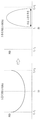
도 13 은 본 발명의 실시예에서 사용될 수 있는 협대역 빔포밍시 도플러 스펙트럼의 분포도를 나타내는 도면이다.
도 14 는 초고주파 대역에서 협대역 빔포밍시 도플러 스팩트럼이 감소되는 모습을 나타내는 도면이다.
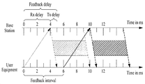
도 15 는 본 발명의 실시예들에서 사용될 수 있는 CQI 보고 방법 중 하나를 나타내는 도면이다.
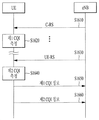
도 16 은 본 발명의 실시예로서 다중 CQI 정보를 송수신하는 방법 중 하나를 나타내는 도면이다.
도 17 에서 설명하는 장치는 도 1 내지 도 16 에서 설명한 방법들이 구현될 수 있는 수단이다.Are included as a part of the detailed description to facilitate understanding of the present invention, and the accompanying drawings provide various embodiments of the present invention. Further, the accompanying drawings are used to describe embodiments of the present invention in conjunction with the detailed description.
FIG. 1 is a view for explaining physical channels that can be used in embodiments of the present invention and a signal transmission method using the same.
2 shows a structure of a radio frame used in embodiments of the present invention.
3 is a diagram illustrating a resource grid for a downlink slot that may be used in embodiments of the present invention.
4 illustrates a structure of an uplink subframe that can be used in embodiments of the present invention.
5 shows a structure of a downlink subframe that can be used in embodiments of the present invention.
6 shows a symbol configuration diagram that can be used in embodiments of the present invention.
7 is a diagram illustrating an example of a subframe to which a cell specific reference signal (CRS) is allocated, which can be used in embodiments of the present invention.
FIG. 8 is a diagram illustrating an example of subframes allocated by CSI-RS according to the number of antenna ports, which can be used in embodiments of the present invention.
9 is a diagram showing an example of a sub-frame to which a UE-specific reference signal (UE-RS) is allocated, which can be used in embodiments of the present invention.
10 is a diagram showing an example of a DSA that can be configured in embodiments of the present invention.
11 is a diagram illustrating a concept of a DSA base station hotel that can be used in embodiments of the present invention.
FIG. 12 is a view showing a frequency band of a small cell that can be used in embodiments of the present invention. FIG.
13 is a diagram showing a distribution diagram of a Doppler spectrum in a narrowband beamforming that can be used in an embodiment of the present invention.
14 is a view showing a state in which the Doppler spectrum is reduced in a narrowband beamforming in a very high frequency band.
15 is a diagram illustrating one of the CQI reporting methods that may be used in embodiments of the present invention.
16 is a diagram illustrating one of methods for transmitting and receiving multiple CQI information according to an embodiment of the present invention.
The apparatus described in Fig. 17 is a means by which the methods described in Figs. 1 to 16 can be implemented.
본 발명은 초고주파 대역을 지원하는 무선 접속 시스템에 관한 것으로, 초고주파 대역에서 채널 노화 효과를 고려한 채널 품질 지시(CQI) 정보를 송수신하는 방법 및 이를 지원하는 장치들을 제공한다.The present invention relates to a radio access system supporting a very high frequency band, and a method of transmitting and receiving channel quality indication (CQI) information considering channel aging effects in a very high frequency band and devices supporting the same.
이하의 실시예들은 본 발명의 구성요소들과 특징들을 소정 형태로 결합한 것들이다. 각 구성요소 또는 특징은 별도의 명시적 언급이 없는 한 선택적인 것으로 고려될 수 있다. 각 구성요소 또는 특징은 다른 구성요소나 특징과 결합되지 않은 형태로 실시될 수 있다. 또한, 일부 구성요소들 및/또는 특징들을 결합하여 본 발명의 실시예를 구성할 수도 있다. 본 발명의 실시예들에서 설명되는 동작들의 순서는 변경될 수 있다. 어느 실시예의 일부 구성이나 특징은 다른 실시예에 포함될 수 있고, 또는 다른 실시예의 대응하는 구성 또는 특징과 교체될 수 있다.The following embodiments are a combination of elements and features of the present invention in a predetermined form. Each component or characteristic may be considered optional unless otherwise expressly stated. Each component or feature may be implemented in a form that is not combined with other components or features. In addition, some of the elements and / or features may be combined to form an embodiment of the present invention. The order of the operations described in the embodiments of the present invention may be changed. Some configurations or features of certain embodiments may be included in other embodiments, or may be replaced with corresponding configurations or features of other embodiments.
도면에 대한 설명에서, 본 발명의 요지를 흐릴 수 있는 절차 또는 단계 등은 기술하지 않았으며, 당업자의 수준에서 이해할 수 있을 정도의 절차 또는 단계는 또한 기술하지 아니하였다.In the description of the drawings, there is no description of procedures or steps that may obscure the gist of the present invention, nor is any description of steps or steps that can be understood by those skilled in the art.
본 명세서에서 본 발명의 실시예들은 기지국과 이동국 간의 데이터 송수신 관계를 중심으로 설명되었다. 여기서, 기지국은 이동국과 직접적으로 통신을 수행하는 네트워크의 종단 노드(terminal node)로서의 의미가 있다. 본 문서에서 기지국에 의해 수행되는 것으로 설명된 특정 동작은 경우에 따라서는 기지국의 상위 노드(upper node)에 의해 수행될 수도 있다.The embodiments of the present invention have been described herein with reference to a data transmission / reception relationship between a base station and a mobile station. Here, the base station is meaningful as a terminal node of a network that directly communicates with a mobile station. The specific operation described herein as performed by the base station may be performed by an upper node of the base station, as the case may be.
즉, 기지국을 포함하는 다수의 네트워크 노드들(network nodes)로 이루어지는 네트워크에서 이동국과의 통신을 위해 수행되는 다양한 동작들은 기지국 또는 기지국 이외의 다른 네트워크 노드들에 의해 수행될 수 있다. 이때, '기지국'은 고정국(fixed station), Node B, eNode B(eNB), 발전된 기지국(ABS: Advanced Base Station) 또는 억세스 포인트(access point) 등의 용어에 의해 대체될 수 있다.That is, various operations performed for communication with a mobile station in a network consisting of a plurality of network nodes including a base station may be performed by a base station or other network nodes other than the base station. At this time, the 'base station' may be replaced by terms such as a fixed station, a Node B, an eNode B (eNB), an Advanced Base Station (ABS) or an access point.
또한, 본 발명의 실시예들에서 단말(Terminal)은 사용자 기기(UE: User Equipment), 이동국(MS: Mobile Station), 가입자 단말(SS: Subscriber Station), 이동 가입자 단말(MSS: Mobile Subscriber Station), 이동 단말(Mobile Terminal) 또는 발전된 이동단말(AMS: Advanced Mobile Station) 등의 용어로 대체될 수 있다.Also, in the embodiments of the present invention, a terminal may be a user equipment (UE), a mobile station (MS), a subscriber station (SS), a mobile subscriber station (MSS) , A mobile terminal, or an advanced mobile station (AMS).
또한, 송신단은 데이터 서비스 또는 음성 서비스를 제공하는 고정 및/또는 이동 노드를 말하고, 수신단은 데이터 서비스 또는 음성 서비스를 수신하는 고정 및/또는 이동 노드를 의미한다. 따라서, 상향링크에서는 이동국이 송신단이 되고, 기지국이 수신단이 될 수 있다. 마찬가지로, 하향링크에서는 이동국이 수신단이 되고, 기지국이 송신단이 될 수 있다.Also, the transmitting end refers to a fixed and / or mobile node providing data service or voice service, and the receiving end means a fixed and / or mobile node receiving data service or voice service. Therefore, in the uplink, the mobile station may be the transmitting end and the base station may be the receiving end. Similarly, in a downlink, a mobile station may be a receiving end and a base station may be a transmitting end.
본 발명의 실시예들은 무선 접속 시스템들인 IEEE 802.xx 시스템, 3GPP(3rd Generation Partnership Project) 시스템, 3GPP LTE 시스템 및 3GPP2 시스템 중 적어도 하나에 개시된 표준 문서들에 의해 뒷받침될 수 있으며, 특히, 본 발명의 실시예들은 3GPP TS 36.211, 3GPP TS 36.212, 3GPP TS 36.213, 3GPP TS 36.321 및/또는 3GPP TS 36.331 문서들에 의해 뒷받침 될 수 있다. 즉, 본 발명의 실시예들 중 설명하지 않은 자명한 단계들 또는 부분들은 상기 문서들을 참조하여 설명될 수 있다. 또한, 본 문서에서 개시하고 있는 모든 용어들은 상기 표준 문서에 의해 설명될 수 있다.Embodiments of the present invention may be supported by the standard documents disclosed in at least one of the IEEE 802.xx system, the 3rd Generation Partnership Project (3GPP) system, the 3GPP LTE system and the 3GPP2 system, May be supported by the documents 3GPP TS 36.211, 3GPP TS 36.212, 3GPP TS 36.213, 3GPP TS 36.321 and / or 3GPP TS 36.331. That is, self-explaining steps or parts not described in the embodiments of the present invention can be described with reference to the documents. In addition, all terms disclosed in this document may be described by the standard document.
이하, 본 발명에 따른 바람직한 실시 형태를 첨부된 도면을 참조하여 상세하게 설명한다. 첨부된 도면과 함께 이하에 개시될 상세한 설명은 본 발명의 예시적인 실시형태를 설명하고자 하는 것이며, 본 발명이 실시될 수 있는 유일한 실시형태를 나타내고자 하는 것이 아니다.Hereinafter, preferred embodiments according to the present invention will be described in detail with reference to the accompanying drawings. DETAILED DESCRIPTION OF THE PREFERRED EMBODIMENTS The following detailed description, together with the accompanying drawings, is intended to illustrate exemplary embodiments of the invention and is not intended to represent the only embodiments in which the invention may be practiced.
또한, 본 발명의 실시예들에서 사용되는 특정(特定) 용어들은 본 발명의 이해를 돕기 위해서 제공된 것이며, 이러한 특정 용어의 사용은 본 발명의 기술적 사상을 벗어나지 않는 범위에서 다른 형태로 변경될 수 있다.In addition, the specific terms used in the embodiments of the present invention are provided to facilitate understanding of the present invention, and the use of such specific terms can be changed to other forms without departing from the technical idea of the present invention .
이하의 기술은 CDMA(code division multiple access), FDMA(frequency division multiple access), TDMA(time division multiple access), OFDMA(orthogonal frequency division multiple access), SC-FDMA(single carrier frequency division multiple access) 등과 같은 다양한 무선 접속 시스템에 적용될 수 있다.The following description is to be understood as illustrative and non-limiting, such as code division multiple access (CDMA), frequency division multiple access (FDMA), time division multiple access (TDMA), orthogonal frequency division multiple access (OFDMA), single carrier frequency division multiple access And can be applied to various wireless connection systems.
CDMA 는 UTRA(Universal Terrestrial Radio Access)나 CDMA2000 과 같은 무선 기술(radio technology)로 구현될 수 있다. TDMA 는 GSM(Global System for Mobile communications)/GPRS(General Packet Radio Service)/EDGE(Enhanced Data Rates for GSM Evolution)와 같은 무선 기술로 구현될 수 있다. OFDMA 는 IEEE 802.11 (Wi-Fi), IEEE 802.16 (WiMAX), IEEE 802-20, E-UTRA(Evolved UTRA) 등과 같은 무선 기술로 구현될 수 있다.CDMA may be implemented in radio technology such as Universal Terrestrial Radio Access (UTRA) or CDMA2000. The TDMA may be implemented in a wireless technology such as Global System for Mobile communications (GSM) / General Packet Radio Service (GPRS) / Enhanced Data Rates for GSM Evolution (EDGE). OFDMA may be implemented in wireless technologies such as IEEE 802.11 (Wi-Fi), IEEE 802.16 (WiMAX), IEEE 802-20, and Evolved UTRA (E-UTRA).
UTRA 는 UMTS(Universal Mobile Telecommunications System)의 일부이다. 3GPP LTE(Long Term Evolution)은 E-UTRA 를 사용하는 E-UMTS(Evolved UMTS)의 일부로써, 하향링크에서 OFDMA 를 채용하고 상향링크에서 SC-FDMA 를 채용한다. LTE-A(Advanced) 시스템은 3GPP LTE 시스템이 개량된 시스템이다. 본 발명의 기술적 특징에 대한 설명을 명확하게 하기 위해, 본 발명의 실시예들을 3GPP LTE/LTE-A 시스템을 위주로 기술하지만 IEEE 802.16e/m 시스템 등에도 적용될 수 있다.UTRA is part of the Universal Mobile Telecommunications System (UMTS). 3GPP Long Term Evolution (LTE) is a part of E-UMTS (Evolved UMTS) using E-UTRA, adopting OFDMA in downlink and SC-FDMA in uplink. The LTE-A (Advanced) system is an improved 3GPP LTE system. In order to clarify the technical features of the present invention, the embodiments of the present invention are described mainly in the 3GPP LTE / LTE-A system, but can also be applied to the IEEE 802.16e / m system and the like.
1. 3GPP LTE/LTE_A 시스템1. 3GPP LTE / LTE_A system
무선 접속 시스템에서 단말은 하향링크(DL: Downlink)를 통해 기지국으로부터 정보를 수신하고, 상향링크(UL: Uplink)를 통해 기지국으로 정보를 전송한다. 기지국과 단말이 송수신하는 정보는 일반 데이터 정보 및 다양한 제어 정보를 포함하고, 이들이 송수신 하는 정보의 종류/용도에 따라 다양한 물리 채널이 존재한다.In a wireless access system, a terminal receives information from a base station through a downlink (DL) and transmits information to a base station through an uplink (UL). The information transmitted and received between the base station and the terminal includes general data information and various control information, and there are various physical channels depending on the type / use of the information transmitted / received.
1.1 시스템 일반1.1 System General
도 1 은 본 발명의 실시예들에서 사용될 수 있는 물리 채널들 및 이들을 이용한 신호 전송 방법을 설명하기 위한 도면이다.FIG. 1 is a view for explaining physical channels that can be used in embodiments of the present invention and a signal transmission method using the same.
전원이 꺼진 상태에서 다시 전원이 켜지거나, 새로이 셀에 진입한 단말은 S11 단계에서 기지국과 동기를 맞추는 등의 초기 셀 탐색 (Initial cell search) 작업을 수행한다. 이를 위해 단말은 기지국으로부터 주동기 채널 (P-SCH: Primary Synchronization Channel) 및 부동기 채널 (S-SCH: Secondary Synchronization Channel)을 수신하여 기지국과 동기를 맞추고, 셀 ID 등의 정보를 획득한다.The terminal that is powered on again after power is turned off or a terminal that has entered a new cell performs an initial cell search operation such as synchronizing with the base station in step S11. To this end, a mobile station receives a primary synchronization channel (P-SCH) and a secondary synchronization channel (S-SCH) from a base station, synchronizes with the base station, and acquires information such as a cell ID.
그 후, 단말은 기지국으로부터 물리방송채널 (PBCH: Physical Broadcast Channel) 신호를 수신하여 셀 내 방송 정보를 획득할 수 있다. 한편, 단말은 초기 셀 탐색 단계에서 하향링크 참조 신호 (DL RS: Downlink Reference Signal)를 수신하여 하향링크 채널 상태를 확인할 수 있다.Then, the terminal can receive the physical broadcast channel (PBCH) signal from the base station and acquire the in-cell broadcast information. Meanwhile, the UE can receive the downlink reference signal (DL RS) in the initial cell search step to check the downlink channel state.
초기 셀 탐색을 마친 단말은 S12 단계에서 물리하향링크제어채널 (PDCCH: Physical Downlink Control Channel) 및 물리하향링크제어채널 정보에 따른 물리하향링크공유 채널 (PDSCH: Physical Downlink Control Channel)을 수신하여 조금 더 구체적인 시스템 정보를 획득할 수 있다.Upon completion of the initial cell search, the UE receives a physical downlink control channel (PDCCH) and a physical downlink control channel (PDSCH) according to physical downlink control channel information in step S12, Specific system information can be obtained.
이후, 단말은 기지국에 접속을 완료하기 위해 이후 단계 S13 내지 단계 S16 과 같은 임의 접속 과정 (Random Access Procedure)을 수행할 수 있다. 이를 위해 단말은 물리임의접속채널 (PRACH: Physical Random Access Channel)을 통해 프리앰블 (preamble)을 전송하고(S13), 물리하향링크제어채널 및 이에 대응하는 물리하향링크공유 채널을 통해 프리앰블에 대한 응답 메시지를 수신할 수 있다(S14). 경쟁 기반 임의 접속의 경우, 단말은 추가적인 물리임의접속채널 신호의 전송(S15) 및 물리하향링크제어채널 신호 및 이에 대응하는 물리하향링크공유 채널 신호의 수신(S16)과 같은 충돌해결절차 (Contention Resolution Procedure)를 수행할 수 있다.Thereafter, the terminal may perform a random access procedure such as steps S13 to S16 to complete the connection to the base station. To this end, the UE transmits a preamble through a Physical Random Access Channel (PRACH) (S13), and transmits a response message to the preamble through the physical downlink control channel and the corresponding physical downlink shared channel (S14). In the case of a contention-based random access, the UE transmits a physical random access channel signal (S15) and a Contention Resolution procedure (S16) such as a physical downlink control channel signal and a corresponding physical downlink shared channel signal Procedure can be performed.
상술한 바와 같은 절차를 수행한 단말은 이후 일반적인 상/하향링크 신호 전송 절차로서 물리하향링크제어채널 신호 및/또는 물리하향링크공유채널 신호의 수신(S17) 및 물리상향링크공유채널 (PUSCH: Physical Uplink Shared Channel) 신호 및/또는 물리상향링크제어채널 (PUCCH: Physical Uplink Control Channel) 신호의 전송(S18)을 수행할 수 있다.The UE having performed the procedure described above transmits a physical downlink control channel signal and / or physical downlink shared channel signal (S17) and a physical uplink shared channel (PUSCH: physical (S18) of an uplink shared channel (PUCCH) signal and / or a physical uplink control channel (PUCCH) signal.
단말이 기지국으로 전송하는 제어정보를 통칭하여 상향링크 제어정보(UCI: Uplink Control Information)라고 지칭한다. UCI 는 HARQ-ACK/NACK (Hybrid Automatic Repeat and reQuest Acknowledgement/Negative-ACK), SR (Scheduling Request), CQI (Channel Quality Indication), PMI (Precoding Matrix Indication), RI (Rank Indication) 정보 등을 포함한다.Control information transmitted from the UE to the Node B is collectively referred to as uplink control information (UCI). The UCI includes HARQ-ACK / NACK (Hybrid Automatic Repeat and Request Acknowledgment / Negative-ACK), SR (Scheduling Request), CQI (Channel Quality Indication), PMI (Precoding Matrix Indication) .
LTE 시스템에서 UCI 는 일반적으로 PUCCH 를 통해 주기적으로 전송되지만, 제어정보와 트래픽 데이터가 동시에 전송되어야 할 경우 PUSCH 를 통해 전송될 수 있다. 또한, 네트워크의 요청/지시에 의해 PUSCH 를 통해 UCI 를 비주기적으로 전송할 수 있다.In the LTE system, the UCI is periodically transmitted through the PUCCH in general, but may be transmitted through the PUSCH when the control information and the traffic data are to be simultaneously transmitted. In addition, UCI can be transmitted non-periodically through the PUSCH according to the request / instruction of the network.
도 2 는 본 발명의 실시예들에서 사용되는 무선 프레임의 구조를 나타낸다.2 shows a structure of a radio frame used in embodiments of the present invention.
도 2(a)는 타입 1 프레임 구조(frame structure type 1)를 나타낸다. 타입 1 프레임 구조는 전이중(full duplex) FDD(Frequency Division Duplex) 시스템과 반이중(half duplex) FDD 시스템 모두에 적용될 수 있다.2 (a) shows a
하나의 무선 프레임(radio frame)은 T f = 307200·T s = 10 ms 의 길이를 가지고, T slot = 15360·Ts = 0.5 ms 의 균등한 길이를 가지며 0 부터 19 의 인덱스가 부여된 20 개의 슬롯으로 구성된다. 하나의 서브프레임은 2 개의 연속된 슬롯으로 정의되며, i 번째 서브프레임은 2i 와 2i+1 에 해당하는 슬롯으로 구성된다. 즉, 무선 프레임(radio frame)은 10 개의 서브프레임(subframe)으로 구성된다. 하나의 서브프레임을 전송하는 데 걸리는 시간을 TTI(transmission time interval)이라 한다. 여기서, Ts 는 샘플링 시간을 나타내고, Ts=1/(15kHz×2048)=3.2552×10-8(약 33ns)로 표시된다. 슬롯은 시간 영역에서 복수의 OFDM 심볼 또는 SC-FDMA 심볼을 포함하고, 주파수 영역에서 복수의 자원블록(Resource Block)을 포함한다.One radio frame has a length of T f = 307200 · T s = 10 ms, has an equal length of T slot = 15360 · T s = 0.5 ms, and 20 frames with an index of 0 to 19 Slots. One subframe is defined as two consecutive slots, and the i-th subframe consists of slots corresponding to 2i and 2i + 1. That is, a radio frame is composed of 10 subframes. The time required to transmit one subframe is referred to as a transmission time interval (TTI). Here, Ts represents the sampling time, and is represented by Ts = 1 / (15 kHz x 2048) = 3.2552 x 10⁻⁸ (about 33 ns). A slot includes a plurality of OFDM symbols or SC-FDMA symbols in a time domain, and a plurality of resource blocks in a frequency domain.
하나의 슬롯은 시간 영역에서 복수의 OFDM(orthogonal frequency division multiplexing) 심볼을 포함한다. 3GPP LTE 는 하향링크에서 OFDMA 를 사용하므로 OFDM 심볼은 하나의 심볼 구간(symbol period)을 표현하기 위한 것이다. OFDM 심볼은 하나의 SC-FDMA 심볼 또는 심볼 구간이라고 할 수 있다. 자원 블록(resource block)은 자원 할당 단위이고, 하나의 슬롯에서 복수의 연속적인 부 반송파(subcarrier)를 포함한다.One slot includes a plurality of orthogonal frequency division multiplexing (OFDM) symbols in the time domain. Since 3GPP LTE uses OFDMA in the downlink, an OFDM symbol is intended to represent one symbol period. The OFDM symbol may be one SC-FDMA symbol or a symbol interval. A resource block is a resource allocation unit and includes a plurality of consecutive subcarriers in one slot.
전이중 FDD 시스템에서는 각 10ms 구간 동안 10 개의 서브프레임은 하향링크 전송과 상향링크 전송을 위해 동시에 이용될 수 있다. 이때, 상향링크와 하향링크 전송은 주파수 영역에서 분리된다. 반면, 반이중 FDD 시스템의 경우 단말은 전송과 수신을 동시에 할 수 없다.In a full-duplex FDD system, 10 subframes can be used simultaneously for downlink transmission and uplink transmission for each 10 ms interval. At this time, the uplink and downlink transmissions are separated in the frequency domain. On the other hand, in the case of a half-duplex FDD system, the UE can not transmit and receive simultaneously.
상술한 무선 프레임의 구조는 하나의 예시에 불과하며, 무선 프레임에 포함되는 서브 프레임의 수 또는 서브 프레임에 포함되는 슬롯의 수, 슬롯에 포함되는 OFDM 심볼의 수는 다양하게 변경될 수 있다.The structure of the radio frame is merely an example, and the number of subframes included in a radio frame, the number of slots included in a subframe, and the number of OFDM symbols included in a slot can be variously changed.
도 2(b)는 타입 2 프레임 구조(frame structure type 2)를 나타낸다. 타입 2 프레임 구조는 TDD 시스템에 적용된다. 하나의 무선 프레임(radio frame)은 T f = 307200·T s = 10 ms 의 길이를 가지며, 153600·T s = 5 ms 길이를 가지는 2 개의 하프프레임(half-frame)으로 구성된다. 각 하프프레임은 30720·T s = 1 ms 의 길이를 가지는 5 개의 서브프레임으로 구성된다. i 번째 서브프레임은 2i 와 2i+1 에 해당하는 각 T slot = 15360·T s = 0.5 ms 의 길이를 가지는 2 개의 슬롯으로 구성된다. 여기에서, Ts 는 샘플링 시간을 나타내고, Ts=1/(15kHz×2048)=3.2552×10-8(약 33ns)로 표시된다.2 (b) shows a
타입 2 프레임에는 DwPTS(Downlink Pilot Time Slot), 보호구간(GP: Guard Period), UpPTS(Uplink Pilot Time Slot)인 3 가지의 필드로 구성되는 특별 서브프레임을 포함한다. 여기서, DwPTS 는 단말에서의 초기 셀 탐색, 동기화 또는 채널 추정에 사용된다. UpPTS 는 기지국에서의 채널 추정과 단말의 상향 전송 동기를 맞추는 데 사용된다. 보호구간은 상향링크와 하향링크 사이에 하향링크 신호의 다중경로 지연으로 인해 상향링크에서 생기는 간섭을 제거하기 위한 구간이다.The
다음 표 1 는 특별 프레임의 구성(DwPTS/GP/UpPTS의 길이)을 나타낸다.Table 1 below shows the composition of the special frame (DwPTS / GP / UpPTS length).

도 3 은 본 발명의 실시예들에서 사용될 수 있는 하향링크 슬롯에 대한 자원 그리드(resource grid)를 예시한 도면이다.3 is a diagram illustrating a resource grid for a downlink slot that may be used in embodiments of the present invention.
도 3 을 참조하면, 하나의 하향링크 슬롯은 시간 영역에서 복수의 OFDM 심볼을 포함한다. 여기서, 하나의 하향링크 슬롯은 7 개의 OFDM 심볼을 포함하고, 하나의 자원 블록은 주파수 영역에서 12 개의 부 반송파를 포함하는 것을 예시적으로 기술하나, 이에 한정되는 것은 아니다.Referring to FIG. 3, one downlink slot includes a plurality of OFDM symbols in a time domain. Herein, one downlink slot includes 7 OFDM symbols, and one resource block includes 12 subcarriers in the frequency domain. However, the present invention is not limited thereto.
자원 그리드 상에서 각 요소(element)를 자원 요소(resource element)하고, 하나의 자원 블록은 12 × 7 개의 자원 요소를 포함한다. 하향링크 슬롯에 포함되는 자원 블록들의 수 NDL 은 하향링크 전송 대역폭(bandwidth)에 종속한다. 상향링크 슬롯의 구조는 하향링크 슬롯의 구조와 동일할 수 있다.Each element on the resource grid is a resource element, and one resource block contains 12 × 7 resource elements. The number of resource blocks NDL included in the downlink slot is dependent on the downlink transmission bandwidth. The structure of the uplink slot may be the same as the structure of the downlink slot.
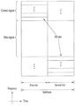
도 4 는 본 발명의 실시예들에서 사용될 수 있는 상향링크 서브 프레임의 구조를 나타낸다.4 illustrates a structure of an uplink subframe that can be used in embodiments of the present invention.
도 4 를 참조하면, 상향링크 서브 프레임은 주파수 영역에서 제어 영역과 데이터 영역으로 나눌 수 있다. 제어 영역에는 상향링크 제어 정보를 나르는 PUCCH 이 할당된다. 데이터 영역은 사용자 데이터를 나르는 PUSCH 이 할당된다. 단일 반송파 특성을 유지하기 위해 하나의 단말은 PUCCH 와 PUSCH 을 동시에 전송하지 않는다. 하나의 단말에 대한 PUCCH 에는 서브 프레임 내에 RB 쌍이 할당된다. RB 쌍에 속하는 RB 들은 2 개의 슬롯들의 각각에서 서로 다른 부 반송파를 차지한다. 이를 PUCCH 에 할당된 RB 쌍은 슬롯 경계(slot boundary)에서 주파수 도약(frequency hopping)된다고 한다.Referring to FIG. 4, the uplink subframe can be divided into a control region and a data region in the frequency domain. A PUCCH for carrying UL control information is allocated to the control region. The data area is assigned a PUSCH carrying user data. To maintain a single carrier characteristic, one UE does not transmit PUCCH and PUSCH at the same time. An RB pair is allocated to a PUCCH for one UE in a subframe. RBs belonging to the RB pair occupy different subcarriers in each of the two slots. It is assumed that the RB pair assigned to the PUCCH is frequency hopped at the slot boundary.
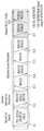
도 5 는 본 발명의 실시예들에서 사용될 수 있는 하향링크 서브 프레임의 구조를 나타낸다.5 shows a structure of a downlink subframe that can be used in embodiments of the present invention.
도 5 를 참조하면, 서브 프레임내의 첫번째 슬롯에서 OFDM 심볼 인덱스 0 부터 최대 3 개의 OFDM 심볼들이 제어 채널들이 할당되는 제어 영역(control region)이고, 나머지 OFDM 심볼들은 PDSCH 이 할당되는 데이터 영역(data region)이다. 3GPP LTE 에서 사용되는 하향링크 제어 채널의 일례로 PCFICH(Physical Control Format Indicator Channel), PDCCH, PHICH(Physical Hybrid-ARQ Indicator Channel) 등이 있다.Referring to FIG. 5, a control region in which control channels are allocated to a maximum of three OFDM symbols starting from an
PCFICH 는 서브 프레임의 첫 번째 OFDM 심볼에서 전송되고, 서브 프레임 내에 제어 채널들의 전송을 위하여 사용되는 OFDM 심볼들의 수(즉, 제어 영역의 크기)에 관한 정보를 나른다. PHICH 는 상향 링크에 대한 응답 채널이고, HARQ (Hybrid Automatic Repeat Request)에 대한 ACK (Acknowledgement)/NACK (Negative-Acknowledgement) 신호를 나른다. PDCCH 를 통해 전송되는 제어 정보를 하향링크 제어정보(DCI: downlink control information)라고 한다. 하향링크 제어 정보는 상향링크 자원 할당 정보, 하향링크 자원 할당 정보 또는 임의의 단말 그룹에 대한 상향링크 전송(Tx) 파워 제어 명령을 포함한다.The PCFICH is carried in the first OFDM symbol of the subframe and carries information about the number of OFDM symbols (i.e., the size of the control region) used for transmission of control channels in the subframe. The PHICH is a response channel for the uplink and carries an ACK (Acknowledgment) / NACK (Negative-Acknowledgment) signal for HARQ (Hybrid Automatic Repeat Request). The control information transmitted through the PDCCH is referred to as downlink control information (DCI). The downlink control information includes uplink resource allocation information, downlink resource allocation information, or an uplink transmission (Tx) power control command for an arbitrary terminal group.
도 6 은 본 발명의 실시예들에서 사용될 수 있는 심볼 구성도를 나타낸다.6 shows a symbol configuration diagram that can be used in embodiments of the present invention.
본 발명의 실시예들에서는 도 6 과 같이 두 가지 형태의 프레임 구조를 지원할 수 있다. 이는 LTE/LTE-A 시스템이 셀룰러 시스템의 다양한 시나리오를 지원하기 위함이다.In the embodiments of the present invention, two types of frame structures can be supported as shown in FIG. This is because LTE / LTE-A systems support various scenarios of cellular systems.
LTE/LTE-A 시스템은 실내, 도심, 교외, 지방 환경을 커버하도록 설계되었으며, 단말의 이동속도는 350-500km 까지를 고려한다. LTE/LTE-A 시스템이 운용되는 중심주파수는 400MHz 에서 4GHz 가 일반적이며, 가용 주파수 대역은 1.4-20MHz 이다. 이것은 중심 주파수와 가용 주파수 대역에 따라 지연 확산(delay spread)과 도플러 주파수(Doppler' s frequency)가 서로 상이할 수 있음을 의미한다.The LTE / LTE-A system is designed to cover indoor, urban, suburban and local environments, and the mobile speed of the terminal can be up to 350-500 km. The center frequency at which the LTE / LTE-A system operates is typically 400 MHz to 4 GHz, and the available frequency band is 1.4 to 20 MHz. This means that the delay spread and the Doppler's frequency may differ from each other depending on the center frequency and the available frequency band.
도 6 을 참조하면, 일반 CP(Normal Cyclic Prefix)의 경우, 서브캐리어 간격(subcarrier spacing)은 Δf=15kHz 이며, CP 는 약 4.7us 이다. 또한, 확장된 CP(Extended CP)의 경우에도 서브캐리어 간격은 동일하며, CP 는 약 16.7us 이다. 확장된 CP 는 긴 CP 구간(duration)으로 인해 상대적으로 넓은 교외 또는 지방에 설치된 넓은 범위의 셀에 대한 지원이 가능하다.Referring to FIG. 6, in the case of a normal CP (Normal Cyclic Prefix), a subcarrier spacing is Δf = 15 kHz, and a CP is about 4.7 us. Also, in the case of the extended CP (CP), the subcarrier interval is the same, and the CP is about 16.7 us. Extended CPs can support a wide range of cells installed in relatively large suburbs or provinces due to the long CP duration.
일반적으로 교외 또는 지방에 설치된 셀일수록 지연 확산의 길이가 길어지기 때문에, 심볼간간섭(ISI: Inter-Symbol Interference)을 확실하게 해결하기 위해서 상대적으로 긴 구간을 갖는 확장 CP 가 필요하지만, 노멀 CP 에 비해 상대적인 오버헤드의 증가로 인해서 스펙트럼 효율(spectral efficiency)/전송 자원(transmission resource) 상의 손실이 발생하는 트레이드 오프(trade-off)가 존재한다.Generally, since a delay spread length becomes longer in a cell installed in a suburban area or a local area, an extended CP having a relatively long interval is required to reliably solve the inter-symbol interference (ISI). However, There is a trade-off in which loss in spectral efficiency / transmission resource occurs due to an increase in relative overhead.
따라서, LTE/LTE-A 시스템은 이와 같은 모든 셀 배치 시나리오들을 지원하기 위해서 일반 CP/확장 CP 의 값을 고정하여 사용하고 있으며, CP 길이를 결정하는 데에는 아래와 같은 설계 기준을 사용하였다.Therefore, in order to support all the cell deployment scenarios, the LTE / LTE-A system uses the fixed CP / extended CP values and uses the following design criteria to determine the CP length.

이때, TCP 는 CP 의 시간 구간을 의미하고, Td 는 지연확산 구간을 의미하며, Δf 는 서브캐리어 간격을 의미한다. 또한, fdmax 는 최대 도플러 확산 값을 나타낸다.In this case, T CP denotes a time interval of CP, T d denotes a delay spread period, and Δ f denotes a sub-carrier interval. Also, f dmax represents the maximum Doppler spread value.
1.2 PDCCH(Physical Downlink Control Channel)1.2 PDCCH (Physical Downlink Control Channel)
1.2.1 PDCCH 일반1.2.1 PDCCH General
PDCCH 는 DL-SCH(Downlink Shared Channel)의 자원 할당 및 전송 포맷(즉, 하향링크 그랜트(DL-Grant)), UL-SCH(Uplink Shared Channel)의 자원 할당 정보(즉, 상향링크 그랜트(UL-Grant)), PCH(Paging Channel)에서의 페이징(paging) 정보, DL-SCH 에서의 시스템 정보, PDSCH 에서 전송되는 랜덤 액세스 응답(random access response)과 같은 상위 레이어(upper-layer) 제어 메시지에 대한 자원 할당, 임의의 단말 그룹 내 개별 단말들에 대한 전송 파워 제어 명령들의 집합, VoIP(Voice over IP)의 활성화 여부에 관한 정보 등을 나를 수 있다.The PDCCH includes resource allocation information of uplink shared channel (DL-SCH) (i.e., downlink grant (DL-Grant), UL-SCH (uplink shared channel) Layer control message, such as paging information in the Paging Channel (PCH), system information in the DL-SCH, and a random access response transmitted on the PDSCH, Resource allocation, a set of transmission power control commands for individual terminals in an arbitrary terminal group, information on whether to activate Voice over IP (VoIP), and the like.
복수의 PDCCH 가 제어영역 내에서 전송될 수 있으며, 단말은 복수의 PDCCH 를 모니터링할 수 있다. PDCCH 는 하나 또는 몇몇 연속적인 CCE(control channel elements)의 집합(aggregation)으로 구성된다. 하나 또는 몇몇 연속적인 CCE 의 집합으로 구성된 PDCCH 는 서브블록 인터리빙(subblock interleaving)을 거친 후에 제어 영역을 통해 전송될 수 있다. CCE 는 무선채널의 상태에 따른 부호화율을 PDCCH 에게 제공하기 위해 사용되는 논리적 할당 단위이다. CCE 는 복수의 자원 요소 그룹(REG: resource element group)에 대응된다. CCE 의 수와 CCE 들에 의해 제공되는 부호화율의 연관 관계에 따라 PDCCH 의 포맷 및 가능한 PDCCH 의 비트수가 결정된다.A plurality of PDCCHs can be transmitted in the control domain, and the UE can monitor a plurality of PDCCHs. The PDCCH consists of one or several consecutive aggregation of control channel elements (CCEs). A PDCCH composed of a set of one or several consecutive CCEs can be transmitted through the control domain after subblock interleaving. The CCE is a logical allocation unit used to provide the PDCCH with the coding rate according to the state of the radio channel. The CCE corresponds to a plurality of resource element groups (REGs). The format of the PDCCH and the number of bits of the possible PDCCH are determined according to the relationship between the number of CCEs and the coding rate provided by the CCEs.
1.2.2 PDCCH 구조1.2.2 PDCCH structure
복수의 단말에 대한 다중화된 복수의 PDCCH 가 제어영역 내에서 전송될 수 있다. PDCCH 는 하나 또는 2 이상의 연속적인 CCE 의 집합(CCE aggregation)으로 구성된다. CCE 는 4 개의 자원 요소로 구성된 REG 의 9 개의 세트에 대응하는 단위를 말한다. 각 REG 에는 4 개의 QPSK(Quadrature Phase Shift Keying) 심볼이 매핑된다. 참조 신호(RS: Reference Signal)에 의하여 점유된 자원 요소들은 REG 에 포함되지 않는다. 즉, OFDM 심볼 내에서 REG 의 총 개수는 셀 특정 참조 신호가 존재하는지 여부에 따라 달라질 수 있다. 4 개의 자원 요소를 하나의 그룹에 매핑하는 REG 의 개념은 다른 하향링크 제어 채널(예를 들어, PCFICH 또는 PHICH)에도 적용될 수 있다. PCFICH 또는 PHICH 에 할당되지 않는 REG 를 N REG 라 하면 시스템에서 이용 가능한 CCE 의 개수는 ![]()
![]()
단말의 디코딩 프로세스를 단순화하기 위해서, n 개의 CCE 를 포함하는 PDCCH 포맷은 n 의 배수와 동일한 인덱스를 가지는 CCE 부터 시작될 수 있다. 즉, CCE 인덱스가 i 인 경우 i mod n = 0 을 만족하는 CCE 부터 시작될 수 있다.In order to simplify the decoding process of the UE, the PDCCH format including n CCEs can be started from a CCE having the same index as a multiple of n. That is, if the CCE index is i, it can be started from a CCE satisfying i mod n = 0.
기지국은 하나의 PDCCH 신호를 구성하기 위해 {1, 2, 4, 8} 개의 CCE 들을 사용할 수 있으며, 이때의 {1, 2, 4, 8}은 CCE 집합 레벨(aggregation level)이라고 부른다. 특정 PDCCH 의 전송을 위해 사용되는 CCE 의 개수는 채널 상태에서 따라 기지국에 의하여 결정된다. 예를 들어, 양호한 하향링크 채널 상태(기지국에 가까운 경우)를 가지는 단말을 위한 PDCCH 는 하나의 CCE 만으로 충분할 수 있다. 반면, 좋지 않은 채널 상태(셀 경계에 있는 경우)를 가지는 단말의 경우는 8 개의 CCE 들이 충분한 강인함(robustness)을 위하여 요구될 수 있다. 게다가, PDCCH 의 파워 레벨도 채널 상태에 매칭되어 조절될 수 있다.The base station can use {1, 2, 4, 8} CCEs to construct one PDCCH signal, and {1, 2, 4, 8} at this time is called the CCE aggregation level. The number of CCEs used for transmission of a specific PDCCH is determined by the BS according to the channel state. For example, only one CCE may be sufficient for a PDCCH for a UE having a good downlink channel state (when it is close to a base station). On the other hand, in the case of a terminal having a bad channel condition (in the cell boundary), eight CCEs may be required for sufficient robustness. In addition, the power level of the PDCCH can be adjusted to match the channel state.
다음 표 2 는 PDCCH 포맷을 나타내며, CCE 집합 레벨에 따라 표 2 과 같이 4 가지의 PDCCH 포맷이 지원된다.Table 2 below shows the PDCCH format. Four PDCCH formats are supported according to the CCE aggregation level as shown in Table 2 below.

단말마다 CCE 집합 레벨이 다른 이유는 PDCCH 에 실리는 제어정보의 포맷 또는 MCS(Modulation and Coding Scheme) 레벨이 다르기 때문이다. MCS 레벨은 데이터 코딩에 사용되는 코드 레이트(code rate)와 변조 서열(modulation order)을 의미한다. 적응적인 MCS 레벨은 링크 적응(link adaptation)을 위해 사용된다. 일반적으로 제어정보를 전송하는 제어채널에서는 3~4 개 정도의 MCS 레벨을 고려할 수 있다.The reason why the CCE aggregation level differs from terminal to terminal is that the format of the control information carried on the PDCCH or the Modulation and Coding Scheme (MCS) level is different. The MCS level refers to a code rate and a modulation order used for data coding. The adaptive MCS level is used for link adaptation. In general, three to four MCS levels can be considered in a control channel for transmitting control information.
제어정보의 포맷을 설명하면, PDCCH 를 통해 전송되는 제어정보를 하향링크 제어정보(DCI)라고 한다. DCI 포맷에 따라 PDCCH 페이로드(payload)에 실리는 정보의 구성이 달라질 수 있다. PDCCH 페이로드는 정보 비트(information bit)를 의미한다. 다음 표 3 은 DCI 포맷에 따른 DCI 를 나타낸다.Describing the format of the control information, the control information transmitted through the PDCCH is referred to as downlink control information (DCI). The configuration of the information carried in the PDCCH payload may vary depending on the DCI format. The PDCCH payload means an information bit. Table 3 below shows the DCI according to the DCI format.

표 3 을 참조하면, DCI 포맷으로는 PUSCH 스케줄링을 위한 포맷 0, 하나의 PDSCH 코드워드의 스케줄링을 위한 포맷 1, 하나의 PDSCH 코드워드의 간단한(compact) 스케줄링을 위한 포맷 1A, DL-SCH 의 매우 간단한 스케줄링을 위한 포맷 1C, 폐루프(Closed-loop) 공간 다중화(spatial multiplexing) 모드에서 PDSCH 스케줄링을 위한 포맷 2, 개루프(Open-loop) 공간 다중화 모드에서 PDSCH 스케줄링을 위한 포맷 2A, 상향링크 채널을 위한 TPC(Transmission Power Control) 명령의 전송을 위한 포맷 3 및 3A 가 있다. 또한, 다중 안테나 포트 전송 모드에서 PUSCH 스케줄링을 위한 DCI 포맷 4 가 추가되었다. DCI 포맷 1A 는 단말에 어떤 전송 모드가 설정되어도 PDSCH 스케줄링을 위해 사용될 수 있다.Referring to Table 3, in the DCI format,
DCI 포맷에 따라 PDCCH 페이로드 길이가 달라질 수 있다. 또, PDCCH 페이로드의 종류와 그에 따른 길이는 간단한(compact) 스케줄링인지 여부 또는 단말에 설정된 전송 모드(transmission mode) 등에 의해 달라질 수 있다.The PDCCH payload length may vary depending on the DCI format. In addition, the type of the PDCCH payload and the length thereof may vary depending on whether it is a compact scheduling or a transmission mode set in the UE.
전송 모드는 단말이 PDSCH 를 통한 하향링크 데이터를 수신하기 위해 설정(configuration)될 수 있다. 예를 들어, PDSCH 를 통한 하향링크 데이터는 단말에 대한 스케줄된 데이터(scheduled data), 페이징, 랜덤 액세스 응답 또는 BCCH 를 통한 브로드캐스트 정보 등이 있다. PDSCH 를 통한 하향링크 데이터는 PDCCH 를 통해 시그널되는 DCI 포맷과 관계가 있다. 전송 모드는 상위 계층 시그널링(예를 들어, RRC(Radio Resource Control) 시그널링)을 통해 단말에 반정적으로(semi-statically) 설정될 수 있다. 전송 모드는 싱글 안테나 전송(Single antenna transmission) 또는 멀티 안테나(Multi-antenna) 전송으로 구분할 수 있다.The transmission mode may be configured such that the UE receives downlink data over the PDSCH. For example, downlink data on the PDSCH includes scheduled data for the UE, paging, random access response, or broadcast information on the BCCH. The downlink data over the PDSCH is related to the DCI format signaled via the PDCCH. The transmission mode may be semi-statically set to the terminal via higher layer signaling (e.g., Radio Resource Control (RRC) signaling). The transmission mode can be classified into a single antenna transmission or a multi-antenna transmission.
단말은 상위 계층 시그널링을 통해 반정적(semi-static)으로 전송 모드가 설정된다. 예를 들어, 멀티 안테나 전송에는 전송 다이버시티(Transmit diversity), 개루프(Open-loop) 또는 폐루프(Closed-loop) 공간 다중화(Spatial multiplexing), MU-MIMO(Multi-user-Multiple Input Multiple Output) 또는 빔 형성(Beamforming) 등이 있다. 전송 다이버시티는 다중 송신 안테나에서 동일한 데이터를 전송하여 전송 신뢰도를 높이는 기술이다. 공간 다중화는 다중 송신 안테나에서 서로 다른 데이터를 동시에 전송하여 시스템의 대역폭을 증가시키지 않고 고속의 데이터를 전송할 수 있는 기술이다. 빔 형성은 다중 안테나에서 채널 상태에 따른 가중치를 가하여 신호의 SINR(Signal to Interference plus Noise Ratio)을 증가시키는 기술이다.A terminal is set to a semi-static transmission mode through upper layer signaling. For example, transmission diversity, open-loop or closed-loop spatial multiplexing, multi-user-multiple-input multiple output (MU-MIMO) ) Or beam forming (Beamforming). Transmit diversity is a technique for increasing transmission reliability by transmitting the same data in multiple transmit antennas. Spatial multiplexing is a technique capable of transmitting high-speed data without increasing the bandwidth of the system by simultaneously transmitting different data from multiple transmit antennas. Beamforming is a technique for increasing the SINR (Signal to Interference plus Noise Ratio) of a signal by applying a weight according to channel conditions in multiple antennas.
DCI 포맷은 단말에 설정된 전송 모드에 종속된다(depend on). 단말은 자신에게 설정된 전송 모드에 따라 모니터링하는 참조(Reference) DCI 포맷이 있다. 단말에 설정되는 전송 모드는 다음과 같이 10 개의 전송 모드를 가질 수 있다.The DCI format is dependent on the transmission mode set in the UE. The UE has a reference DCI format for monitoring according to the transmission mode set for the UE. The transmission mode set in the UE can have 10 transmission modes as follows.
·전송모드 1: 단일 안테나 전송· Transmission mode 1: Single antenna transmission
·전송모드 2: 송신 다이버시티• Transmit mode 2: Transmit diversity
·전송모드 3: 레이어가 1 개보다 큰 경우에는 개루프(open-Ioop) 코드북 기반 프리코딩, rank 가 1 인 경우에는 송신 다이버시티Transmission mode 3: Open-Ioop codebook-based precoding when the layer is larger than 1, transmit diversity when rank is 1,
·전송모드 4: 폐루프(closed-loop) 코드북 기반 프리코딩Transmission mode 4: Closed-loop codebook-based precoding
·전송모드 5: 전송모드 4 버전의 다중사용자(multi-user) MIMO· Transmission mode 5:
·전송모드 6: 단일 레이어 전송으로 제한된 특수한 경우의 폐루프 코드북 기반 프리코딩Transmission mode 6: closed-loop codebook-based precoding in a special case limited to single-layer transmission
·전송모드 7: 단일 레이어 전송만을 지원하는 코드북에 기반하지 않은 프리코딩 (release 8)Transmission mode 7: precoding not based on a codebook that supports only single layer transmission (release 8)
·전송모드 8: 최대 2 개의 레이어까지 지원하는 코드북에 기반하지 않은 프리코딩 (release 9)· Transmission mode 8: Precoding (release 9) based not on codebooks supporting up to two layers.
·전송모드 9: 최대 8 개의 레이어까지 지원하는 코드북에 기반하지 않은 프리코딩 (release 10)• Transmission mode 9: Precoding (release 10) based not on codebooks supporting up to 8 layers;
·전송모드 10: 최대 8 개의 레이어까지 지원하는 코드북에 기반하지 않은 프리코딩 , COMP 용도 (release 11)· Transmission mode 10: precoding not based on a codebook supporting up to 8 layers, use of COMP (release 11)
1.2.3 PDCCH 전송1.2.3 PDCCH transmission
기지국은 단말에게 전송하려는 DCI 에 따라 PDCCH 포맷을 결정하고, 제어 정보에 CRC(Cyclic Redundancy Check)를 붙인다. CRC 에는 PDCCH 의 소유자(owner)나 용도에 따라 고유한 식별자(예를 들어, RNTI(Radio Network Temporary Identifier))가 마스킹된다. 특정의 단말을 위한 PDCCH 라면 단말의 고유한 식별자(예를 들어, C-RNTI(Cell-RNTI))가 CRC 에 마스킹될 수 있다. 또는 페이징 메시지를 위한 PDCCH 라면 페이징 지시 식별자(예를 들어, P-RNTI(Paging-RNTI))가 CRC 에 마스킹될 수 있다. 시스템 정보, 더욱 구체적으로 시스템 정보 블록(system information block, SIB)를 위한 PDCCH 라면 시스템 정보 식별자(예를 들어, SI-RNTI(system information RNTI))가 CRC 에 마스킹될 수 있다. 단말의 랜덤 액세스 프리앰블의 전송에 대한 응답인 랜덤 액세스 응답을 지시하기 위하여 RA-RNTI(random access-RNTI)가 CRC 에 마스킹될 수 있다.The base station determines the PDCCH format according to the DCI to be transmitted to the UE, and attaches a CRC (Cyclic Redundancy Check) to the control information. The CRC is masked with a unique identifier (e.g., Radio Network Temporary Identifier (RNTI)) according to the owner or use of the PDCCH. A unique identifier (e.g., C-RNTI (Cell-RNTI)) of the UE may be masked in the CRC if it is a PDCCH for a particular UE. Or a PDCCH for a paging message, a paging indication identifier (e.g., P-RNTI (P-RNTI)) may be masked to the CRC. A system information identifier (e.g., SI-RNTI) may be masked to the CRC if the PDCCH is for a system information, more specifically a system information block (SIB). A random access-RNTI (RA-RNTI) may be masked in the CRC to indicate a random access response that is a response to the transmission of the UE's random access preamble.
이어, 기지국은 CRC 가 부가된 제어정보를 채널 코딩을 수행하여 부호화된 데이터(coded data)를 생성한다. 이때, MCS 레벨에 따른 코드 레이트로 채널 코딩을 수행할 수 있다. 기지국은 PDCCH 포맷에 할당된 CCE 집합 레벨에 따른 전송률 매칭(rate matching)을 수행하고, 부호화된 데이터를 변조하여 변조 심볼들을 생성한다. 이때, MCS 레벨에 따른 변조 서열을 사용할 수 있다. 하나의 PDCCH 를 구성하는 변조 심볼들은 CCE 집합 레벨이 1, 2, 4, 8 중 하나일 수 있다. 이후, 기지국은 변조 심볼들을 물리적인 자원요소에 맵핑(CCE to RE mapping)한다.Then, the base station generates coded data by performing channel coding on the control information to which the CRC is added. At this time, channel coding can be performed at a code rate according to the MCS level. The base station performs rate matching according to the CCE aggregation level allocated to the PDCCH format, and modulates the coded data to generate modulation symbols. At this time, a modulation sequence according to the MCS level can be used. The modulation symbols constituting one PDCCH may be one of
1.2.4 블라인드 디코딩(BS: Blind Decoding)1.2.4 Blind Decoding (BS)
하나의 서브프레임 내에서 복수의 PDCCH 가 전송될 수 있다. 즉, 하나의 서브프레임의 제어영역은 인덱스 0 ~ N CCE,k - 1 을 가지는 복수의 CCE 로 구성된다. 여기서, N CCE,k 는 k 번째 서브프레임의 제어 영역 내에 총 CCE 의 개수를 의미한다. 단말은 매 서브프레임마다 복수의 PDCCH 들을 모니터링한다. 여기서, 모니터링이란 단말이 모니터링되는 PDCCH 포맷에 따라 PDCCH 들의 각각의 디코딩을 시도하는 것을 말한다.A plurality of PDCCHs can be transmitted in one subframe. That is, the control region of one subframe is composed of a plurality of
서브프레임 내에서 할당된 제어영역에서 기지국은 단말에게 해당하는 PDCCH 가 어디에 있는지에 관한 정보를 제공하지 않는다. 단말은 기지국으로부터 전송된 제어채널을 수신하기 위해서 자신의 PDCCH 가 어느 위치에서 어떤 CCE 집합 레벨이나 DCI 포맷으로 전송되는지 알 수 없으므로, 단말은 서브프레임 내에서 PDCCH 후보(candidate)들의 집합을 모니터링하여 자신의 PDCCH 를 찾는다. 이를 블라인드 디코딩(BD)이라 한다. 블라인드 디코딩은 단말이 CRC 부분에 자신의 단말 식별자(UE ID)를 디 마스킹(De-Masking) 시킨 후, CRC 오류를 검토하여 해당 PDCCH 가 자신의 제어채널인지 여부를 확인하는 방법을 말한다.In the control region allocated in the subframe, the BS does not provide information on where the corresponding PDCCH is located to the UE. Since the UE can not know from which position its CCE aggregation level or DCI format is transmitted in order to receive the control channel transmitted from the Node B, the UE monitors the set of PDCCH candidates in the subframe, Lt; / RTI > This is referred to as blind decoding (BD). Blind decoding refers to a method in which a UE de-masks its UE ID in a CRC field and then checks CRC errors to determine whether the corresponding PDCCH is its own control channel.
활성 모드(active mode)에서 단말은 자신에게 전송되는 데이터를 수신하기 위해 매 서브프레임의 PDCCH 를 모니터링한다. DRX 모드에서 단말은 매 DRX 주기의 모니터링 구간에서 깨어나(wake up) 모니터링 구간에 해당하는 서브프레임에서 PDCCH 를 모니터링한다. PDCCH 의 모니터링이 수행되는 서브프레임을 non-DRX 서브프레임이라 한다.In the active mode, the UE monitors the PDCCH of each subframe in order to receive data transmitted to the UE. In the DRX mode, the UE wakes up in a monitoring interval of every DRX period and monitors the PDCCH in a subframe corresponding to the monitoring interval. The subframe in which the PDCCH is monitored is called a non-DRX subframe.
단말은 자신에게 전송되는 PDCCH 를 수신하기 위해서는 non-DRX 서브프레임의 제어영역에 존재하는 모든 CCE 에 대해 블라인드 디코딩을 수행해야 한다. 단말은 어떤 PDCCH 포맷이 전송될지 모르므로, 매 non-DRX 서브프레임 내에서 PDCCH 의 블라인드 디코딩이 성공할 때까지 가능한 CCE 집단 레벨로 PDCCH 를 모두 디코딩해야 한다. 단말은 자신을 위한 PDCCH 가 몇 개의 CCE 를 사용하는지 모르기 때문에 PDCCH 의 블라인드 디코딩이 성공할 때까지 가능한 모든 CCE 집단 레벨로 검출을 시도해야 한다.In order to receive the PDCCH transmitted to the UE, the UE must perform blind decoding on all CCEs present in the control region of the non-DRX subframe. Since the UE does not know which PDCCH format is to be transmitted, the UE must decode all of the PDCCHs at a possible CCE aggregation level until the blind decoding of the PDCCH succeeds in every non-DRX subframe. Since the UE does not know how many CCEs the PDCCH for itself uses, it should try to detect all possible CCE aggregation levels until the blind decoding of the PDCCH succeeds.
LTE 시스템에서는 단말의 블라인드 디코딩을 위해서 서치 스페이스(SS: Search Space) 개념을 정의한다. 서치 스페이스는 단말이 모니터링하기 위한 PDCCH 후보 세트를 의미하며, 각 PDCCH 포맷에 따라 상이한 크기를 가질 수 있다. 서치 스페이스는 공용 서치 스페이스(CSS: Common Search Space)와 단말 특정 서치 스페이스(USS: UE-specific/Dedicated Search Space)로 구성될 수 있다.In the LTE system, a search space (SS) concept is defined for blind decoding of a terminal. The search space refers to a PDCCH candidate set for monitoring by the UE, and may have a different size according to each PDCCH format. The search space may be composed of a common search space (CSS) and a UE-specific / dedicated search space (USS).
공용 서치 스페이스의 경우, 모든 단말이 공용 서치 스페이스의 크기에 대하여 알 수 있으나, 단말 특정 서치 스페이스는 각 단말마다 개별적으로 설정될 수 있다. 따라서, 단말은 PDCCH 를 디코딩하기 위해 단말 특정 서치 스페이스 및 공용 서치 스페이스를 모두 모니터링해야 하며, 따라서 하나의 서브프레임에서 최대 44 번의 블라인드 디코딩(BD)을 수행하게 된다. 여기에는 상이한 CRC 값(예를 들어, C-RNTI, P-RNTI, SI-RNTI, RA-RNTI)에 따라 수행하는 블라인드 디코딩은 포함되지 않는다.In the case of the common search space, all the terminals can know the size of the common search space, but the terminal specific search space can be set individually for each terminal. Accordingly, the UE must monitor both the UE-specific search space and the common search space in order to decode the PDCCH, thereby performing a maximum of 44 blind decoding (BD) in one sub-frame. But does not include blind decoding performed in accordance with different CRC values (e.g., C-RNTI, P-RNTI, SI-RNTI, RA-RNTI).
서치 스페이스의 제약으로 인하여, 기지국은 주어진 서브프레임 내에서 PDCCH 를 전송하고자 하는 단말들 모두에게 PDCCH 를 전송하기 위한 CCE 자원이 확보될 수 없는 경우가 발생할 수 있다. 왜냐하면, CCE 위치가 할당되고 남은 자원들은 특정 단말의 서치 스페이스 내에 포함되지 않을 수 있기 때문이다. 다음 서브프레임에도 계속될 수 있는 이러한 장벽을 최소화하기 위하여 단말 특정 도약(hopping) 시퀀스가 단말 특정 서치 스페이스의 시작 지점에 적용될 수 있다.Due to the restriction of the search space, the BS may not be able to secure the CCE resources for transmitting the PDCCH to all the UEs that intend to transmit the PDCCH within a given subframe. This is because the CCE location is allocated and the remaining resources may not be included in the search space of the specific terminal. A UE-specific hopping sequence may be applied to the beginning of the UE-specific search space to minimize such barriers that may continue in the next sub-frame.
표 4 는 공용 서치 스페이스와 단말 특정 서치 스페이스의 크기를 나타낸다.Table 4 shows the sizes of the public search space and the UE-specific search space.

블라인드 디코딩을 시도하는 횟수에 따른 단말의 부하를 경감하기 위해, 단말은 정의된 모든 DCI 포맷에 따른 서치를 동시에 수행하지 않는다. 구체적으로, 단말은 단말 특정 서치 스페이스에서 항상 DCI 포맷 0 과 1A 에 대한 서치를 수행한다. 이때, DCI 포맷 0 과 1A 는 동일한 크기를 가지나, 단말은 PDCCH 에 포함된 DCI 포맷 0 과 1A 를 구분하는데 사용되는 플래그(flag for format 0/format 1A differentiation)를 이용하여 DCI 포맷을 구분할 수 있다. 또한, 단말에 DCI 포맷 0 과 DCI 포맷 1A 외에 다른 DCI 포맷이 요구될 수 있는데, 그 일례로 DCI 포맷 1, 1B, 2 가 있다.In order to reduce the load of the UE according to the number of attempts of blind decoding, the UE does not simultaneously perform search according to all defined DCI formats. Specifically, the terminal always searches for
공용 서치 스페이스에서 단말은 DCI 포맷 1A 와 1C 를 서치할 수 있다. 또한 단말은 DCI 포맷 3 또는 3A 를 서치하도록 설정될 수 있으며, DCI 포맷 3 과 3A 는 DCI 포맷 0 과 1A 와 동일한 크기를 가지나, 단말은 단말 특정 식별자가 아닌 다른 식별자에 의하여 스크램블된 CRC 를 이용하여 DCI 포맷을 구별할 수 있다.In the public search space, the terminal can search DCI formats 1A and 1C. Also, the terminal can be set to search for
서치 스페이스 ![]()
![]()
![]()
![]()
여기서, M (L) 은 서치 스페이스에서 모니터하기 위한 CCE 집합 레벨 L 에 따른 PDCCH 후보들의 개수를 나타내며, m = 0,…,M (L)-1 이다. i 는 각 PDCCH 후보에서 개별 CCE 를 지정하는 인덱스로서 i = 0,…,L-1 이다. ![]()
![]()
상술한 바와 같이, 단말은 PDCCH 를 디코딩하기 위해 단말 특정 서치 스페이스 및 공용 서치 스페이스를 모두 모니터링한다. 여기서, 공용 서치 스페이스(CSS)는 {4, 8}의 집합 레벨을 갖는 PDCCH 들을 지원하고, 단말 특정 서치 스페이스(USS)는 {1, 2, 4, 8}의 집합 레벨을 갖는 PDCCH 들을 지원한다. 표 5 는 단말에 의하여 모니터링되는 PDCCH 후보를 나타낸다.As described above, the UE monitors both the UE-specific search space and the common search space in order to decode the PDCCH. Here, the common search space CSS supports PDCCHs having aggregate levels of {4, 8}, and the UE-specific search space USS supports PDCCHs having aggregate levels of {1, 2, 4, 8} . Table 5 shows the PDCCH candidates monitored by the UE.

수학식 1 을 참조하면, 공용 서치 스페이스의 경우 2 개의 집합 레벨, L=4 및 L=8 에 대해 Y k 는 0 으로 설정된다. 반면, 집합 레벨 L 에 대해 단말 특정 서치 스페이스의 경우 Y k 는 수학식 2 와 같이 정의된다.Referring to Equation (1), Y k is set to 0 for two aggregate levels, L = 4 and L = 8 for the common search space. On the other hand, in the case of the UE-specific search space for the set level L, Y k is defined as shown in Equation (2).
![]()
![]()
여기서, Y -1 = n RNTI ≠ 0 이며, n RNTI RNTI 값을 나타낸다. 또한, A = 39827 이고, D = 65537 이다.Where Y -1 = n RNTI ≠ 0 and n RNTI represents the RNTI value. Also, A = 39827 and D = 65537.
1.3 참조신호(RS: Reference Signal)1.3 Reference signal (RS)
이하에서는 본 발명의 실시예들에서 사용될 수 있는 참조신호들에 대해서 설명한다.Hereinafter, reference signals that can be used in embodiments of the present invention will be described.
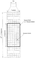
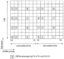
도 7은 본 발명의 실시예들에서 사용될 수 있는 셀 특정 참조 신호(CRS: Cell specific Reference Signal)가 할당된 서브프레임의 일례를 나타내는 도면이다.7 is a diagram illustrating an example of a subframe to which a cell specific reference signal (CRS) is allocated, which can be used in embodiments of the present invention.
도 7에서는 시스템에서 4개 안테나를 지원하는 경우에 CRS의 할당 구조를 나타낸다. 3GPP LTE/LTE-A 시스템에서 CRS는 디코딩 및 채널 상태 측정을 목적으로 사용된다. 따라서, CRS는 PDSCH 전송을 지원하는 셀(cell) 내 모든 하향링크 서브프레임에서 전체 하향링크 대역폭에 걸쳐 전송되며, 기지국(eNB)에 구성된 모든 안테나 포트에서 전송된다.FIG. 7 shows a CRS allocation structure when the system supports four antennas. In the 3GPP LTE / LTE-A system, CRS is used for decoding and channel state measurement purposes. Therefore, the CRS is transmitted over all downlink bandwidths in all downlink subframes in a cell supporting PDSCH transmission, and is transmitted from all antenna ports configured in the base station (eNB).
구체적으로 CRS 시퀀스 ![]()
![]()
![]()
![]()
![]()
![]()
여기서, ns에는 무선 프레임 내 슬롯 번호이며 l은 상기 슬롯 내 OFDM 심볼 번호로서, 다음 수학식 4에 따라 결정된다.Where n s is the slot number in the radio frame and 1 is the OFDM symbol number in the slot and is determined according to the following equation (4).

여기서, k는 부반송파 인덱스이고 ![]()
![]()
![]()
![]()

셀-특정적 주파수 천이 v shift는 다음과 같이 물리 계층 셀 식별자(physical layer cell identity) ![]()
![]()
![]()
![]()
UE는 CRS를 이용하여 CSI를 측정할 수 있으며, CRS를 이용하여 CRS를 포함하는 서브프레임에서 PDSCH를 통해 수신된 하향링크 데이터 신호를 디코딩할 수 있다. 즉, eNB는 모든 RB에서 각 RB 내 일정한 위치에 CRS를 전송하고 UE는 상기 CRS를 기준으로 채널 추정을 수행한 다음에 PDSCH를 검출하였다. 예를 들어, UE는 CRS RE에서 수신된 신호를 측정한다. UE는 CRS RE별 수신 에너지와 PDSCH이 맵핑된 RE별 수신 에너지에 대한 비를 이용하여 PDSCH가 맵핑된 RE로부터 PDSCH 신호를 검출할 수 있다.The UE can measure the CSI using the CRS and can decode the downlink data signal received through the PDSCH in the subframe including the CRS using the CRS. That is, the eNB transmits a CRS to a certain position in each RB in all RBs, and the UE detects the PDSCH after performing channel estimation based on the CRS. For example, the UE measures the signal received at the CRS RE. The UE can detect the PDSCH signal from the RE to which the PDSCH is mapped using the ratio of the reception energy per RE to the RE to the RE energy mapped to the PDSCH mapped to the RE.
이와 같이, CRS를 기반으로 PDSCH 신호가 전송되는 경우에, eNB는 모든 RB에 대해서 CRS를 전송해야 하므로 불필요한 RS 오버헤드가 발생하게 된다. 이러한 문제점을 해결하기 위하여 3GPP LTE-A 시스템에서는 CRS 외에 UE-특정 RS(이하, UE-RS) 및 채널상태정보 참조신호(CSI-RS: Channel State Information Reference Signal)를 추가로 정의한다. UE-RS는 복조를 위해 사용되고, CSI-RS는 채널 상태 정보를 획득하기(derive) 위해 사용된다.In this way, when the PDSCH signal is transmitted based on the CRS, the eNB needs to transmit the CRS to all the RBs, so that unnecessary RS overhead is generated. In order to solve this problem, a UE-specific RS (hereinafter referred to as UE-RS) and a channel state information reference signal (CSI-RS: Channel State Information Reference Signal) are additionally defined in the 3GPP LTE-A system. The UE-RS is used for demodulation and the CSI-RS is used to derive channel state information.
UE-RS 및 CRS는 복조를 위해 사용되므로 용도의 측면에서 복조용 RS라고 할 수 있다. 즉, UE-RS는 DMRS(DeModulation Reference Signal)의 일종으로 볼 수 있다. 또한, CSI-RS 및 CRS는 채널 측정 혹은 채널 추정에 사용되므로 용도의 측면에서는 채널 상태 측정용 RS라고 할 수 있다.The UE-RS and the CRS are used for demodulation and thus can be referred to as a demodulation RS in terms of usage. That is, the UE-RS can be regarded as a kind of DMRS (DeModulation Reference Signal). In addition, since CSI-RS and CRS are used for channel measurement or channel estimation, they can be referred to as an RS for channel state measurement in terms of application.
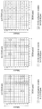
도 8은 본 발명의 실시예들에서 사용될 수 있는 CSI-RS가 안테나 포트의 개수에 따라 할당된 서브프레임들의 일례를 나타내는 도면이다.FIG. 8 is a diagram illustrating an example of subframes allocated by CSI-RS according to the number of antenna ports, which can be used in embodiments of the present invention.
CSI-RS는 복조 목적이 아니라 무선 채널의 상태 측정을 위해 3GPP LTE-A 시스템에서 도입된 하향링크 참조신호이다. 3GPP LTE-A 시스템은 CSI-RS 전송을 위해 복수의 CSI-RS 설정들을 정의하고 있다. CSI-RS 전송이 구성된 서브프레임들에서 CSI-RS 시퀀스 ![]()
![]()
![]()
![]()
![]()
![]()
여기서 w l", k, l은 다음 수학식 8에 의해 주어진다.Here, w l " , k , l is given by the following equation (8).

여기서 (k', l') 및 n s 상의 필요한(necessary) 조건들은 정규 CP 및 확장 CP에 대해 각각 표 6 및 표 7에 의해 주어진다. 즉 표 6 및 표 7의 CSI RS 설정들은 RB 쌍 내에서 각 안테나 포트의 CSI-RS가 점유하는 RE들의 위치를 나타낸다.Where the necessary conditions on ( k ', l ') and n s are given by Tables 6 and 7 for normal CP and extended CP, respectively. That is, the CSI RS settings in Tables 6 and 7 indicate the positions of the REs occupied by the CSI-RS of each antenna port in the RB pair.


도 8(a)는 표 6의 CSI-RS 구성들 중 2개의 CSI-RS 포트들에 의한 CSI-RS 전송에 이용 가능한 20가지 CSI-RS 구성 0~19를 나타낸 것이고, 도 8(b)는 표 6의 CSI-RS 구성들 중 4개의 CSI-RS 포트들에 의해 이용 가능한 10가지 CSI-RS 구성 0~9를 나타낸 것이며, 도 8(c)는 표 6의 CSI-RS 구성 중 8개의 CSI-RS 포트들에 의해 이용 가능한 5가지 CSI-RS 구성 0~4를 도시한 것이다.8 (a) shows 20 CSI-
여기서 CSI-RS 포트는 CSI-RS 전송을 위해 설정된 안테나 포트를 의미한다. 예를 들어, 수학식 8에서 안테나 포트 15~22가 CSI-RS 포트에 해당한다. CSI-RS 포트의 개수에 따라 CSI-RS 구성이 달라지므로 CSI-RS 구성 번호가 동일하다고 하더라도 CSI-RS 전송을 위해 구성된 안테나 포트의 개수가 다르면 다른 CSI-RS 구성이 된다.Here, the CSI-RS port means an antenna port set for CSI-RS transmission. For example, in Equation (8),
한편 CSI-RS는 매 서브프레임마다 전송되도록 구성된 CRS와 달리 다수의 서브프레임들에 해당하는 소정 전송 주기마다 전송되도록 설정된다. 따라서, CSI-RS 구성은 표 6 혹은 표 7에 따른 자원 블록 쌍 내에서 CSI-RS가 점유하는 RE들의 위치뿐만 아니라 CSI-RS가 설정되는 서브프레임에 따라서도 달라진다.On the other hand, the CSI-RS is set to be transmitted every predetermined transmission period corresponding to a plurality of subframes, unlike the CRS configured to transmit every subframe. Therefore, the CSI-RS configuration is different not only according to the location of the REs occupied by the CSI-RS in the resource block pair according to Table 6 or Table 7 but also on the subframe in which the CSI-RS is set.
또한, 표 6 또는 표 7에서 CSI-RS 구성 번호가 동일하다고 하더라도 CSI-RS 전송을 위한 서브프레임이 다르면 CSI-RS 구성도 다르다고 볼 수 있다. 예를 들어, CSI-RS 전송 주기(T CSI-RS)가 다르거나 일 무선 프레임 내에서 CSI-RS 전송이 구성된 시작 서브프레임(ΔCSI-RS)이 다르면 CSI-RS 구성이 다르다고 볼 수 있다.Also, even if the CSI-RS configuration numbers are the same in Table 6 or Table 7, if the CSI-RS transmission subframes are different, the CSI-RS configuration is also different. For example, if the CSI-RS transmission period ( T CSI-RS ) is different or the starting sub-frame ( CSI-RS ) in which CSI-RS transmission is configured in one wireless frame is different, the CSI-RS configuration may be different.
이하에서는 (1) 표 6 또는 표 7의 CSI-RS 구성 번호가 부여된 CSI-RS 구성과 (2) 표 6 또는 표 7의 CSI-RS 구성 번호, CSI-RS 포트의 개수 및/또는 CSI-RS가 구성된 서브프레임에 따라 달라지는 CSI-RS 구성을 구분하기 위하여, 후자의 구성을 CSI-RS 자원 구성(CSI-RS resource configuration)이라고 칭한다. 전자의 설정은 CSI-RS 구성 또는 CSI-RS 패턴이라고도 칭한다.Hereinafter, (1) a CSI-RS configuration number given in Table 6 or Table 7 and (2) a CSI-RS configuration number in Table 6 or Table 7, the number of CSI- The latter configuration is referred to as a CSI-RS resource configuration (CSI-RS resource configuration) in order to distinguish a CSI-RS configuration that varies depending on a subframe in which the RS is configured. The former setting is also referred to as CSI-RS configuration or CSI-RS pattern.
eNB는 UE에게 CSI-RS 자원 구성을 알려줄 때 CSI-RS들의 전송을 위해 사용되는 안테나 포트의 개수, CSI-RS 패턴, CSI-RS 서브프레임 구성(CSI-RS subframe configuration) I CSI-RS, CSI 피드백을 위한 참조 PDSCH 전송 전력에 관한 UE 가정(UE assumption on reference PDSCH transmitted power for CSI feedback) P c, 제로 파워 CSI-RS 구성 리스트, 제로 파워 CSI-RS 서브프레임 구성 등에 관한 정보를 알려 줄 수 있다.The number of antenna ports used for transmission of CSI-RSs, the CSI-RS pattern, the CSI-RS subframe configuration I CSI-RS , and the CSI-RS subframe configuration when informing the UE of the CSI- (UE assumption on reference PDSCH transmitted power for CSI feedback) P c , a zero power CSI-RS configuration list, a zero power CSI-RS subframe configuration, etc. .
CSI-RS 서브프레임 구성 인덱스 I CSI-RS는 CSI-RS들의 존재(occurrence)에 대한 서브프레임 구성 주기 T CSI-RS 및 서브프레임 오프셋 ΔCSI-RS을 특정하는 정보이다. 다음 표 8은 T CSI-RS 및 ΔCSI-RS에 따른 CSI-RS 서브프레임 구성 인덱스 I CSI-RS을 예시한 것이다.The CSI-RS subframe configuration index I CSI-RS is information specifying the subframe configuration period T CSI-RS and the subframe offset CSI-RS for the occurrence of CSI-RSs . The following Table 8 illustrates the CSI-RS subframe configuration index I CSI-RS according to T CSI-RS and CSI-RS .

다음 수학식 9를 만족하는 서브프레임들이 CSI-RS를 포함하는 서브프레임들이 된다.The subframes satisfying the following Equation (9) become subframes including the CSI-RS.
![]()
![]()
3GPP LTE-A 시스템 이후에 정의된 전송 모드(예를 들어, 전송 모드 9 혹은 그 외 새로이 정의되는 전송 모드)로 설정된 UE는 CSI-RS를 이용하여 채널 측정을 수행하고 UE-RS를 이용하여 PDSCH를 복호할 수 있다.A UE set to a transmission mode defined after the 3GPP LTE-A system (e.g.,
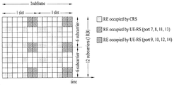
도 9는 본 발명의 실시예들에서 사용될 수 있는 UE-특정 참조 신호(UE-RS)이 할당된 서브프레임의 일례를 나타내는 도면이다.9 is a diagram showing an example of a sub-frame to which a UE-specific reference signal (UE-RS) is allocated, which can be used in embodiments of the present invention.
도 9를 참조하면, 해당 서브프레임은 정규 CP를 갖는 정규 하향링크 서브프레임의 자원블록 쌍 내 RE들 중 UE-RS에 의해 점유되는 RE들을 예시한 것이다.Referring to FIG. 9, the corresponding subframe illustrates the REs occupied by the UE-RS among the REs in the resource block pair of the normal downlink subframe having the normal CP.
UE-RS는 PDSCH 신호의 전송을 위해 지원되며 안테나 포트(들)은 p = 5, p = 7, p = 8 혹은 p = 7,8,...,υ+6 (여기서, υ는 상기 PDSCH의 전송을 위해 사용되는 레이어의 개수)가 될 수 있다. UE-RS는 PDSCH 전송이 해당 안테나 포트와 연관되면 존재하고, PDSCH 신호의 복조(demodulation)를 위해서만 유효한(valid) 참조 신호이다.The UE-RS is supported for transmission of a PDSCH signal and the antenna port (s) is p = 5, p = 7, p = 8 or p = 7,8, ..., v + 6, Lt; / RTI > of the layer < RTI ID = 0.0 > The UE-RS exists if the PDSCH transmission is associated with the corresponding antenna port, and is a valid reference signal only for demodulation of the PDSCH signal.
UE-RS는 해당 PDSCH 신호가 맵핑된 RB들 상에서만 전송된다. 즉, UE-RS는 PDSCH의 존재 유무와 관계없이 매 서브프레임마다 전송되도록 설정된 CRS와 달리, PDSCH가 스케줄링된 서브프레임에서 PDSCH가 맵핑된 RB(들)에서만 전송되도록 설정된다. 또한, UE-RS는 PDSCH의 레이어의 개수와 관계없이 모든 안테나 포트(들)을 통해 전송되는 CRS와 달리, PDSCH의 레이어(들)에 각각 대응하는 안테나 포트(들)을 통해서만 전송된다. 따라서 UE-RS를 사용하면, CRS에 비해 RS의 오버헤드가 감소될 수 있다.The UE-RS is transmitted only on the RBs to which the corresponding PDSCH signal is mapped. That is, the UE-RS is set such that the PDSCH is transmitted only in the PDSCH-mapped RB (s) in the scheduled subframe, unlike the CRS set to be transmitted in every subframe regardless of the presence or absence of the PDSCH. Also, the UE-RS is only transmitted via the antenna port (s) corresponding to the layer (s) of the PDSCH, unlike the CRS transmitted via all antenna port (s) regardless of the number of layers of the PDSCH. Therefore, using the UE-RS, the overhead of the RS can be reduced as compared with the CRS.
3GPP LTE-A 시스템에서 UE-RS는 PRB 쌍에서 정의된다. 도 9를 참조하면, p = 7, p = 8 혹은 p = 7,8,...,υ+6에 대해, 해당 PDSCH 전송을 위해 할당(assign)된 주파수-도메인 인덱스 nPRB를 갖는 PRB에서, UE-RS 시퀀스 r(m)의 일부가 다음 수학식 10에 따라 서브프레임에서 복소 변조 심볼들 ![]()
![]()
![]()
![]()
여기서 wp(i), l', m'은 다음 수학식 11과 같이 주어진다.Here, w p (i), l ', m' are given by Equation (11).

여기서 정규 CP를 위한 시퀀스 ![]()
![]()

안테나 포트 p ∈ {7,8,...,υ+6}에 대해 UE-RS 시퀀스 r(m)은 다음 수학식 12와 같이 정의된다.The UE-RS sequence r ( m ) for antenna port p ∈ {7,8, ..., v + 6} is defined as:
![]()
![]()
c(i)는 의사-임의(pseudo-random) 시퀀스로서, 길이-31 골드(Gold) 시퀀스에 의해 정의된다. 길이 M PN인 출력 시퀀스 c(n)(여기서 n = 0,1,..., M PN-1)는 다음 수학식 13에 의해 정의된다. c ( i ) is a pseudo-random sequence defined by a length-31 Gold sequence. The output sequence c ( n ) with length M PN (where n = 0,1, ..., M PN -1) is defined by:

여기서 N C=1600이고 첫 번째 m-시퀀스는 x 1(0)=1, x 1(n)=0, n=1,2,...,30으로 초기화되며 두 번째 m-시퀀스는 상기 시퀀스의 적용에 따른 값을 지닌 ![]()
![]()
수학식 13에서 c(i)의 생성을 위한 임의-의사 시퀀스 생성기는 각 서브프레임의 시작에서 다음의 수학식 14에 따라 c init으로 초기화된다.The random-pseudo-sequence generator for generating c ( i ) in
![]()
![]()
여기서, n SCID의 값은 달리 특정되지 않으면 0이며, 안테나 포트 7 혹은 8 상의 PDSCH 전송에 대해 n SCID는 PDSCH 전송과 연관된 DCI 포맷 2B 혹은 2C에 의해 주어진다. DCI 포맷 2B는 UE-RS를 갖는 안테나 포트를 최대 2개까지 이용하는 PDSCH를 위한 자원 배정(resource assignment)을 위한 DCI 포맷이며, DCI 포맷 2C는 UE-RS를 갖는 안테나 포트를 최대 8개까지 이용하는 PDSCH를 위한 자원 배정(resource assignment)을 위한 DCI 포맷이다.Here, the value of n SCID is 0 unless otherwise specified, and for the PDSCH transmission on
수학식 10부터 수학식 14에서 알 수 있듯이 UE-RS는 PDSCH의 레이어(들)에 각각 대응하는 안테나 포트(들)을 통해 전송된다. 즉 수학식 10부터 수학식 14에 의하면 UE-RS 포트의 개수는 PDSCH의 전송 랭크에 비례함을 알 수 있다. 한편 레이어의 개수가 1 또는 2인 경우에는 RB 쌍별로 12개의 RE들이 UE-RS 전송에 사용되며, 레이어의 개수가 2보다 많은 경우에는 RB쌍별로 24개의 RE들이 UE-RS 전송에 사용된다. 또한 UE 혹은 셀에 관계없이 RB 쌍에서 UE-RS에 의해 점유된 RE(즉, UE-RS RE)들의 위치는 UE-RS 포트별로 동일하다.As can be seen from Equations (10) through (14), the UE-RS is transmitted via the antenna port (s) corresponding to the layer (s) of the PDSCH. That is, from Equation (10) to Equation (14), it can be seen that the number of UE-RS ports is proportional to the transmission rank of the PDSCH. On the other hand, when the number of layers is 1 or 2, twelve REs are used for UE-RS transmission per RB pair, and when the number of layers is more than 2, 24 REs are used for UE-RS transmission per RB pair. Also, the positions of the REs (i.e., UE-RS REs) occupied by the UE-RS in the RB pair, regardless of the UE or cell, are the same for each UE-RS port.
결국 특정 서브프레임에서 특정 UE를 위한 PDSCH가 맵핑된 RB에서는 DMRS RE의 개수는 동일하다. 다만 동일 서브프레임에 서로 다른 UE에게 할당된 RB들에서는 전송되는 레이어의 개수에 따라 해당 RB들에 포함된 DMRS RE의 개수는 달라질 수 있다.As a result, the number of DMRS REs in the RB to which the PDSCH for a specific UE is mapped in a specific subframe is the same. However, in the RBs allocated to different UEs in the same subframe, the number of DMRS REs included in the corresponding RBs may vary depending on the number of layers to be transmitted.
2. 초고주파 대역을 지원하는 무선 접속 시스템2. Wireless access system supporting ultra-high frequency band
2.1 분산형 안테나 시스템(DAS: Distributed Antenna System)2.1 Distributed Antenna System (DAS)
현재의 무선 통신 환경은 기기간(M2M: Machine-to-Machine) 통신의 지원과 높은 데이터 전송 용량을 요구하는 스마트폰 및 태블릿 PC등의 다양한 디바이스의 출현과 보급으로 셀룰러망에 대한 데이터 요구량이 매우 빠르게 증가하고 있다. 높은 데이터 요구량을 만족시키기 위해 통신 기술은 더 많은 주파수 대역을 효율적으로 사용하기 위한 캐리어 결합(CA: Carrier Aggregation) 기술, 인지 무선 통신(cognitive radio communication) 기술 등과 한정된 주파수 내에서 데이터 용량을 높이기 위해 다중 안테나 기술, 다중 기지국 협력 기술 등으로 발전하고 있다.The present wireless communication environment is very fast in terms of data demand for cellular networks due to the emergence and spread of various devices such as smart phones and tablet PCs that require high data transmission capacity and support for machine-to-machine communication (M2M) . In order to meet high data requirements, communication technologies have been developed for the purpose of increasing the data capacity within a limited frequency, such as Carrier Aggregation (CA) technology, cognitive radio communication technology and the like to efficiently use more frequency bands. Antenna technology, and multi-base station cooperation technology.
또한, 통신 환경은 사용자 주변에 접속할 수 있는 접속점(AP: Access Point)의 밀도가 점점 높아지는 방향으로 진화하고 있다. 이러한 AP 는 셀룰러 마이크로 AP(Cellular Macro AP)뿐만 아니라 와이파이 AP(WiFi AP), 셀룰러 팸토 AP(Cellular Femto AP), 셀룰러 피코 AP(Cellular Pico AP) 등 이 존재한다. 이렇게 작은 커버리지를 갖는 여러 AP 가 하나의 셀 내에 존재함으로 인해 시스템 전체에서 데이터 사용량이 증가하고 있다. 용량을 늘리려 한다. 이러한 AP 는 원격 무선 헤드(RRH: Remote Radio Head) 또는, DAS(Distributed Antenna System)의 안테나 노드(Antenna Node) 등과 같은 형태도 가능하다.In addition, the communication environment evolves toward a higher density of access points (APs) that can be connected to the user's surroundings. Such an AP includes not only a cellular micro AP but also a WiFi AP, a cellular femto AP, and a cellular pico AP. Since there are several APs with such a small coverage in one cell, data usage is increasing in the entire system. I want to increase the capacity. The AP may be a remote radio head (RRH) or an antenna node of a distributed antenna system (DAS).
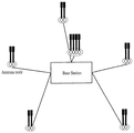
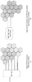
도 10 은 본 발명의 실시예들에서 구성될 수 있는 DSA 의 일례를 나타내는 도면이다.10 is a diagram showing an example of a DSA that can be configured in embodiments of the present invention.
DAS 시스템은 기지국(BS: Base Station)의 안테나들이 셀 중앙에 몰려 있는 집중형 안테나 시스템(CAS: Centralized Antenna System) 시스템과 달리 셀 내의 다양한 위치에 퍼져 있는 안테나들을 단일 기지국에서 관리하는 시스템을 의미한다. DAS 은 여러 안테나 노드가 하나의 셀을 구성한다는 점에서 펨토셀 /피코셀과는 구별된다.DAS system refers to a system in which a single base station manages antennas at various locations in a cell, unlike a centralized antenna system (CAS) system in which antennas of a base station (BS) . DAS is distinguished from femtocell / picocell in that multiple antenna nodes constitute one cell.
초기의 DAS 의 용도는 음영지역을 커버하기 위해 안테나를 더 설치하여 리피티션(repetition) 하는 용도였다. 그러나, DAS 는 기지국 안테나들이 동시에 여러 데이터 스트림(data stream)을 송수신하거나 한 명 또는 여러 명의 사용자를 지원할 수 있다는 점에서 일종의 MIMO(Multiple Input Multiple Output) 시스템으로 볼 수 있다. 또한, MIMO 시스템은 높은 스펙트럼 효율(spectral efficiency)로 인해 차세대 통신의 요구사항을 만족시키기 위한 필수적인 요건으로 인식되고 있다.The use of early DAS was to repetitively install additional antennas to cover the shaded area. However, DAS can be viewed as a kind of Multiple Input Multiple Output (MIMO) system in that base station antennas can transmit and receive multiple data streams simultaneously or support one or several users. In addition, the MIMO system is recognized as an essential requirement to meet the requirements of the next generation communication due to its high spectral efficiency.
MIMO 시스템의 관점에서, DAS 는 CAS 보다 사용자와 안테나간의 거리가 작아짐으로써 얻게 되는 높은 전력효율, 낮은 기지국 안테나간의 상관도 및 간섭으로 인한 높은 채널용량, 셀 내의 사용자의 위치와 상관없이 상대적으로 균일한 품질의 통신성능이 확보되는 등의 장점을 갖는다.From the viewpoint of the MIMO system, the DAS is relatively uniform regardless of the location of the user in the cell, the high channel efficiency due to the correlation between the low base station antennas and the interference, and the high power efficiency obtained by reducing the distance between the user and the antenna, Quality communication performance can be ensured.
도 10 을 참조하면, DAS 는 기지국과 그에 연결된 안테나 노드(그룹, cluster, etc.)들로 구성된다. 안테나 노드는 기지국과 유/무선으로 연결되어 있으며 하나 이상의 안테나들을 포함할 수 있다. 일반적으로 한 안테나 노드에 속해 있는 안테나들은 가장 가까운 안테나간의 거리가 수 미터 이내로 지역적으로 같은 위치(spot)에 속해 있는 특성을 지니며, 안테나 노드는 단말이 접속할 수 있는 접속점과 같은 역할을 한다. 기존 DAS 기술들에서는 안테나 노드를 안테나와 동일시 하거나 둘을 구별하지 않은 기술이 많지만, 실제적으로 DAS 를 운용하기 위해서는 둘간의 관계가 명확히 정의 되어야만 한다.Referring to FIG. 10, a DAS includes a base station and an antenna node (group, cluster, etc.) connected thereto. The antenna node may be connected to the base station wirelessly or wirelessly and may include one or more antennas. Generally, antennas belonging to one antenna node have characteristics that the distance between the nearest antennas is within a few meters and locally belong to the same spot, and the antenna node acts as an access point to which the terminal can access. In existing DAS technologies, there are many techniques that identify antenna nodes with antennas or do not distinguish between antennas. However, in order to actually operate DAS, the relationship between two antennas must be clearly defined.
도 11 은 본 발명의 실시예들에서 사용될 수 있는 DSA 의 기지국 호텔의 개념을 나타내는 도면이다.11 is a diagram illustrating a concept of a DSA base station hotel that can be used in embodiments of the present invention.
도 11(a)는 기존 RAN 구조를 나타낸다. 도 11(a)를 참조하면, 기존의 셀룰러 시스템은 하나의 기지국(BTS)이 세 개의 섹터(sector)를 관할하고, 각각의 기지국은 서로 백본망을 통해 BSC/RNC 와 연결되었다.11 (a) shows a conventional RAN structure. Referring to FIG. 11A, in a conventional cellular system, one base station (BTS) manages three sectors, and each base station is connected to the BSC / RNC through a backbone network.
도 11(b)는 DSA 및 BTS 호텔를 포함하는 스몰 셀 RAN 구조를 나타낸다. 도 11(b)를 참조하면, DAS 에서는 각 안테나 노드(AN: Antenna Node)와 연결되는 기지국들을 한곳에 모을 수 있다(BTS hotel). 이로 인해 기지국을 설치할 땅과 건물에 대한 비용을 줄이고, 기지국에 대한 유지 및 관리를 한 곳에서 쉽게 할 수 있으며, BTS 와 MSC/BSC/RNC 를 모두 한 곳에 설치함으로써 백홀 용량(backhaul capacity)을 크게 증가시킬 수 있다.11 (b) shows a small cell RAN structure including a DSA and a BTS hotel. Referring to FIG. 11 (b), in the DAS, the base stations connected to each antenna node (AN) can be collected in one place (BTS hotel). Therefore, it is possible to reduce the cost of land and buildings for the base station and to easily maintain and manage the base station in one place. By installing the BTS and the MSC / BSC / RNC in one place, the backhaul capacity can be increased .
본 발명의 실시예들에서는 BTS 호텔 개념 등을 이용하여 안테나 노드(AN)들로부터, 셀 구성을 순시적으로 변화될 때, 무선통신이 가능 하도록 하는 프레임 구성 방법을 제공하고, 이를 이용해 얻을 수 있는 잠재적인 이득을 설명한다.Embodiments of the present invention provide a frame configuration method for making wireless communication possible when the cell configuration is changed instantaneously from antenna nodes (ANs) by using a BTS hotel concept or the like, Explain the potential benefits.
도 12 는 본 발명의 실시예들에서 사용될 수 있는 스몰셀의 주파수 대역에 을 나타내는 도면이다.FIG. 12 is a view showing a frequency band of a small cell that can be used in embodiments of the present invention. FIG.
도 12 는 스몰셀의 개념을 나타낸다. 즉, 단말에게 기존의 LTE 시스템에 운용되는 주파수 대역이 아닌 높은 중심 주파수를 갖는 대역에 넓은 시스템 대역을 설정하여 운용하는 것을 예상할 수 있다. 또한, 기존의 셀룰러 대역을 통해서는 시스템 정보와 같은 제어 신호를 기반으로 기본적인 셀 커버리지를 지원하고, 고주파의 스몰셀을 통해 넓은 주파수 대역을 이용하여 전송효율을 극대화하는 데이터 전송이 이루어질 수 있음을 의미한다. 따라서, 지역 영역 접속(LAA: Local Area Access)이라는 개념은 보다 좁은 지역에 위치한 중저속 이동(low-to-medium mobility) 단말들이 대상이며, 단말과 기지국 사이의 거리가 기존 km 단위의 셀보다 작은 100m 단위의 작은 셀들이 될 것이다.12 shows the concept of a small cell. That is, it can be expected that a wide system band is set up and operated in a band having a high center frequency, rather than a frequency band used in an existing LTE system. In addition, through the existing cellular band, basic cell coverage is supported based on a control signal such as system information, and data transmission can be achieved by maximizing transmission efficiency by using a wide frequency band through a high frequency small cell do. Therefore, the concept of Local Area Access (LAA) is intended for low-to-medium mobility terminals located in a narrower area, and the distance between the terminal and the base station is smaller than the existing unit of km It will be small cells of 100m units.
따라서 이러한 셀들에서는 단말과 기지국 사이의 거리가 짧아지고, 고주파 대역을 사용함에 따라 다음와 같은 채널 특성을 예상할 수 있다.Therefore, the distance between the terminal and the base station is shortened in these cells, and the following channel characteristics can be expected by using the high frequency band.
(1) 지연 확산(Delay spread): 기지국과 단말 사이의 거리가 짧아짐에 따라 신호의 지연이 짧아질 수 있다.(1) Delay spread: As the distance between the base station and the terminal becomes shorter, the delay of the signal can be shortened.
(2) 서브캐리어 간격(Subcarrier spacing): LTE 와 동일한 OFDM 기반의 프레임을 적용할 경우, 할당된 주파수 대역이 크기 때문에 기존의 15kHz 보다 극단적으로 큰 값으로 설정될 수 있다.(2) Subcarrier spacing: When an OFDM-based frame equal to LTE is applied, the allocated frequency band is large, and thus can be set to an extremely larger value than the existing 15 kHz.
(3) 도플러 주파수(Doppler' s frequency): 고주파 대역을 사용하기 때문에 동일한 속도의 단말은 저주파 대역보다 높은 도플러 주파수가 나타나기 때문에, 상관시간(coherent time)이 극단적으로 짧아질 수 있다.(3) Doppler's frequency: Since a high frequency band is used, a coherent time can be extremely short because a Doppler frequency higher than a low frequency band occurs at the same speed terminal.
2.2 초고주파 대역의 채널 특성 및 도플러 스펙트럼2.2 Channel characteristics and Doppler spectrum of super high frequency band
LTE/LTE-A 시스템은 최대 도플러 주파수를 기반으로 도출된 상관 시간을 기반으로 RS 밀집도 및 패턴을 설계하였다. RS 를 통해 단말은 무선 채널을 추정할 수 있으며, 수신 데이터의 복조를 할 수 있다. 실제로 LTE 시스템은 중심 주파수 2GHz, 단말의 이동속도 500km/h 를 가정하는 경우 최대 도플러 주파수(fd)는 950Hz, 약 1000Hz 가 된다.The LTE / LTE-A system designed the RS density and pattern based on the correlation time derived based on the maximum Doppler frequency. Through the RS, the UE can estimate the wireless channel and demodulate the received data. Actually, the maximum Doppler frequency (f d ) is 950 Hz and about 1000 Hz when the center frequency is 2 GHz in the LTE system and the moving speed of the terminal is 500 km / h.
일반적으로 상관 시간은 최대 도플러 주파수로부터 약 50%을 얻을 수 있다. 따라서 LTE 시스템에서는 다음 수학식 15 와 같은 관계식이 성립한다.In general, the correlation time can be about 50% from the maximum Doppler frequency. Therefore, in the LTE system, the following
![]()
![]()
수학식 15 는 상관 시간 내에 최대 2 개의 RS 가 필요함을 의미한다. 즉 LTE 시스템에서는 이러한 RS 패턴을 구현함으로써, 단말의 최대 이동속도인 500km/h 이하까지 모든 이동 상황에서 채널 추정이 가능하다.Equation (15) implies that a maximum of two RSs are required within the correlation time. In other words, in the LTE system, by implementing the RS pattern, it is possible to perform channel estimation in all mobile situations up to a maximum mobile speed of 500 km / h or less.
그러나, 기존의 셀룰러 이동통신이 서비스되는 3GHz 이하가 아닌 수십 GHz 의 중심 주파수를 갖는 초고주파 대역에서는 상대적으로 저속인 단말도 높은 도플러 주파수를 경험한다. 예를 들어, 중심 주파수가 각각 2GHz 및 20GHz 이고, 단말의 이동속도가 동일하게 30km/h 라고 가정할 때, 최대 도플러 주파수는 다음과 같이 계산될 수 있다.However, relatively low-speed terminals also experience high Doppler frequencies in a very high frequency band having a center frequency of several tens of GHz, which is not lower than 3 GHz, where conventional cellular mobile communication services are provided. For example, assuming that the center frequencies are 2 GHz and 20 GHz, respectively, and the mobile speed of the terminal equals 30 km / h, the maximum Doppler frequency can be calculated as follows.

이때, c=3×10⁸ 으로 동일하고, fc 는 중심 주파수를 나타내며, v 는 단말의 이동 속도를 나타낸다. 즉, 동일한 속도의 이동단말의 경우라도 단말이 통신을 수행하는 주파수 대역의 주파수가 높아지면, 단말은 더 높은 도플러 주파수를 경험하게 된다.At this time, c = 3 × 10 8 , fc represents the center frequency, and v represents the moving speed of the terminal. That is, even in the case of the mobile terminal of the same speed, if the frequency of the frequency band in which the terminal performs communication is high, the terminal experiences a higher Doppler frequency.
또한, 초고주파 대역의 특성상 기존의 수 GHz 이하 무선 채널과 달리 도플러 스펙트럼에 변화된 특성에 직접적인 보상 기법을 적용할 수 있다. 일반적으로 고주파 대역에서는 안테나 요소(element)를 구성하는 파장 λ 가 짧아지기 때문에, 동일한 공간에 많은 안테나를 구비할 수 있는 매시브 안테나(Massive antenna) 구성이 가능하다. 이를 통해 협대역 빔포밍(narrow beamforming) 적용이 보다 용이해진다.In addition, due to the characteristics of a very high frequency band, a direct compensation technique can be applied to the characteristics changed in the Doppler spectrum, unlike the existing few GHz or less radio channels. Generally, in a high frequency band, since a wavelength? Of an antenna element is short, a massive antenna configuration capable of providing many antennas in the same space is possible. This makes it easier to apply narrow beamforming.
또한 수십 GHz 대의 높은 중심 주파수로 인해서 기본 수 GHz 대의 통신 대역보다 큰 경로 손실이 발생하며, 고주파 대역의 특성상 추가적인 환경 손실(Environment Loss) 등의 추가 경로 손실이 발생한다. 따라서 기존의 멀티패스 채널(Multipath channel) 중 산란(scattering)을 통해 반사되어 들어오는 성분들의 추가적인 경로 감쇄가 상대적으로 크기 때문에, LOS(Line Of Sight) 지배적인(dominant) 환경이 만들어질 수 있다. 즉 고주파 대역의 특성상 기지국에서 협대역 빔포밍 기법을 적용하기 용이한 환경이 만들어지는 것이다.In addition, due to the high center frequency of several tens of GHz, path loss is larger than the communication bandwidth of the basic GHz band, and additional path loss such as additional environmental loss occurs due to the characteristics of the high frequency band. Therefore, since the additional path attenuation of the components reflected through the scattering of the existing multipath channel is relatively large, a line-of-sight (LOS) dominant environment can be created. That is, due to the characteristics of a high frequency band, an environment in which a narrowband beam forming technique can be easily applied to a base station is created.
이러한 협대역 빔포밍에 의해서 단말 수신기의 전방향에서 신호가 수신되는 것이 아닌 특정 방향에서만 신호가 수신되기 때문에, 도플러 스펙트럼은 도 13 과 같이 스펙트럼 자체가 뾰족해지는(sharp) 현상이 나타난다.Since the narrowband beamforming does not receive a signal in all directions of the terminal receiver, but a signal is received only in a specific direction, the Doppler spectrum exhibits sharpness of the spectrum itself as shown in FIG.
도 13 은 본 발명의 실시예에서 사용될 수 있는 협대역 빔포밍시 도플러 스펙트럼의 분포도를 나타내는 도면이다.13 is a diagram showing a distribution diagram of a Doppler spectrum in a narrowband beamforming that can be used in an embodiment of the present invention.
도 13(a)는 일반 대역에서의 도플러 스펙트럼을 나타낸다. 가로축은 주파수축이며, 세로축은 전력 스팩트럼 밀도(PSD: Power Spectrum Density) 축이다. 일반 주파수 대역(예를 들어, LTE 시스템 대역)에서는 단말 수신기의 전방향에서 신호가 수신되므로, 단말이 수신하는 신호의 도플러 스펙트럼은 도 13(a)와 같이 U 자 모양을 나타낸다.13 (a) shows the Doppler spectrum in the normal band. The abscissa is the frequency axis, and the ordinate is the power spectral density (PSD) axis. In the general frequency band (for example, the LTE system band), since a signal is received in all directions of the terminal receiver, the Doppler spectrum of the signal received by the terminal shows a U-shape as shown in FIG.
도 13(b)는 초고주파 대역에서의 도플러 스펙트럼을 나타낸다. 초고주파 대역에서는 단말 수신기의 특정 방향에서만 신호가 수신되므로, 단말이 수신하는 신호의 도플러 스펙트럼은 도 13(b)와 같이 변형된다.13 (b) shows the Doppler spectrum in the very high frequency band. In the very high frequency band, since a signal is received only in a specific direction of the terminal receiver, the Doppler spectrum of the signal received by the terminal is modified as shown in FIG. 13 (b).
도 14 는 초고주파 대역에서 협대역 빔포밍시 도플러 스팩트럼이 감소되는 모습을 나타내는 도면이다.14 is a view showing a state in which the Doppler spectrum is reduced in a narrowband beamforming in a very high frequency band.
도 13(b)에서 도시된 도플러 스팩트럼은, 협대역 빔포밍을 고려한 도플러 스펙트럼의 특성을 이용하여 도 14 와 같이 직접 보상이 가능하다. 즉, 스펙트럼이 전체 도플러 스프레드가 아닌 일부 영역에 응집되어 있기 때문에, 수신단에서 자동 주파수 제어(Auto Frequency Control)/적응적 주파수 제어(Adaptive Frequency Control) 기능을 이용하여 도 14 와 같이 최종적인 도플러 스펙트럼 감쇄가 가능해진다.The Doppler spectrum shown in FIG. 13 (b) can be directly compensated as shown in FIG. 14 by using the characteristics of the Doppler spectrum considering narrowband beamforming. That is, since the spectrum is not concentrated in the entire Doppler spread but is concentrated in a certain region, the receiving end uses the auto frequency control / adaptive frequency control function to obtain the final Doppler spectrum attenuation .
즉, AFC 기능을 통해서 최대 도플러 주파수를 fd 가 아닌 fd' (< fd)으로 감소시키면 최대 도플러 주파수와 역함수 관계를 갖는 수학식 18 로 인해 상관 시간은 증가하게 된다. 이것은 시간 축에서 보다 긴 시간 동안 채널이 변하지 않음을 의미하게 된다. 초고주파 대역은 전파 특성으로 인해서 다수 안테나를 이용한 협대역 빔포밍에 친화적인 통신 환경이다. 따라서, 수신단에서는 AFC 를 이용하여 시간 축에서 정적 채널 구간을 증가시킴으로써 보다 안정적인 시변 채널 특성을 가질 수 있다.That is, if the maximum Doppler frequency is reduced to fd '(<fd) rather than fd through the AFC function, the correlation time increases due to Equation (18), which has an inverse relationship with the maximum Doppler frequency. This means that the channel is unchanged for a longer time on the time axis. The very high frequency band is a communication environment that is friendly to narrowband beam forming using multiple antennas due to its propagation characteristics. Therefore, the receiving end can have more stable time-varying channel characteristics by increasing the static channel section on the time axis using AFC.
본 발명의 실시예들은 이와 같이 시변 채널 특성이 극대화되는 통신 환경에서 적용되는 것이다. 다만, 시변 채널 특성이 극대화되는 환경은 초고주파 대역뿐 아니라, 일반 중심 주파수 대역 (예를 들어, 5GHz 이하)에서도 구현될 수 있다. 예를 들어, 단말의 이동 속도가 매우 빠르게 증가하면 도플러 주파수가 높아지므로 일반 중심 주파수 대역에서도 시변 채널 특성이 극대화 되는 통신 환경이 형성될 수 있다.The embodiments of the present invention are applied in a communication environment where the time-varying channel characteristic is maximized. However, the environment in which the time-varying channel characteristic is maximized can be realized not only in the very high frequency band but also in the general center frequency band (for example, 5 GHz or less). For example, since the Doppler frequency increases when the moving speed of the terminal increases very rapidly, a communication environment in which the time-varying channel characteristic is maximized even in the general center frequency band can be formed.
3. 채널 품질 지시자 송수신 방법3. Channel quality indicator transmission / reception method
3.1 고주파 대역의 채널 노화 현상3.1 Channel aging phenomenon in high frequency band
채널 품질 지시자(CQI)는 채널 상태 정보(CSI: Channel State Information)에 포함되는 정보 중 하나이다. 하향링크 채널에 대한 CQI 측정 시점과 기지국이 해당 CQI 정보를 반영하여 데이터를 전송하는 시점에서 채널 변화로 인해 성능 저하가 발생하는 것을 채널 노화(aging)라 한다. 채널 노화 현상은 다음과 같이 정리할 수 있다.A channel quality indicator (CQI) is one of information included in channel state information (CSI). The channel degradation due to the channel change at the time of transmitting the data by reflecting the CQI information of the downlink channel and the CQI information of the base station is called channel aging. The channel aging phenomenon can be summarized as follows.
(1) 하향링크 전송에 있어, 단말의 CSI 측정 시점(t0)과 해당 CSI 를 이용해 기지국이 데이터를 전송하는 시점(t2) 사이에 채널 변화로 인해 성능 저하가 생기는 현상(1) In the downlink transmission, performance deterioration due to a channel change occurs between the CSI measurement time point (t0) of the UE and the time point (t2) at which the base station transmits data using the corresponding CSI
(2) 단말의 CSI 측정 시점(t0)-> 단말의 CSI 보고 시점(t1)->기지국의 CSI 적용된 하향링크 데이터 전송(t2)(2) CSI measurement time of terminal (t0) -> terminal CSI reporting time (t1) -> CSI applied base station downlink data transmission (t2)
(3) 현재 기술의 한계: 현재는 저속 최적화 기술(CL: Closed Loop)과 고속 지원 기술(OL: Open Loop)로 기술이 양분됨(3) Limitations of current technology: Currently, technologies are divided into low-speed optimization (CL) and high-speed support technology (OL: open loop)
(4) 고주파 대역의 한계: 고주파 대역에서는 중심 주파수가 높기 때문에 단말의 낮은 이동속도에도 높은 도플러 주파수를 겪게 된다. 따라서 시간 영역에서의 채널 변화가 보다 큰 채널 환경이 형성된다.(4) Limitation of the high frequency band: Since the center frequency is high in the high frequency band, a high Doppler frequency is experienced even at a low moving speed of the terminal. Therefore, a channel environment with a larger channel change in the time domain is formed.
고주파 대역에서는 앞서 언급한 바와 같이, AFC 에 의해서 비교적 주파수 보상이 용이할 것으로 예측된다. 따라서, 이러한 주파수 보상이 시간 축에서는 정적(static) 채널이 유지되는 상관 시간(Coherence Time)에 영향을 미쳐 채널 상태에 기인한 CQI 도출에도 영향을 미치게 된다.In the high frequency band, as mentioned above, it is expected that the frequency compensation is relatively easy by the AFC. Therefore, the frequency compensation affects the correlation time (coherence time) in which the static channel is maintained in the time domain, thereby affecting the derivation of the CQI due to the channel state.
도 15 는 본 발명의 실시예들에서 사용될 수 있는 CQI 보고 방법 중 하나를 나타내는 도면이다.15 is a diagram illustrating one of the CQI reporting methods that may be used in embodiments of the present invention.
초고주파 대역에서 협대역 빔포밍 시 도플러 스펙트럼이 특정 영역으로 밀집됨을 알 수 있다(도 12 내지 도 14 참조). 결국 고주파 대역에서는 협대역 빔포밍과 AFC 를 이용한 주파수 보상이 이루어지기 유리한 환경임을 알 수 있는데, 이것은 단말과 기지국 사이에 상관 시간이 증가되었음을 의미한다. 즉, 초고주파 대역에서는 채널이 정적인 시간이 증가함으로써, 보다 긴 시간 동안 시간 축에서 채널이 변화하지 않음을 의미한다.It can be seen that the Doppler spectrum is concentrated in a specific region when the narrowband beamforming is performed in the very high frequency band (see FIGS. 12 to 14). As a result, it can be seen that in the high frequency band, the narrowband beamforming and the frequency compensation using the AFC are favorable environments, which means that the correlation time between the terminal and the base station is increased. That is, in the very high frequency band, since the time of the static channel increases, it means that the channel does not change in the time axis for a longer time.
셀룰러 시스템에서는 단말이 리포팅하는 CQI 정보를 이용하여 기지국이 스케줄링을 수행한다. 도 7 을 참조하면, LTE 시스템에서는 단말이 4ms 주기로 CQI 를 기지국에 피드백하고, 기지국은 일정한 1ms 송신 지연(delay)을 가지고 하향링크 데이터를 송신한다. 이때 단말로의 송신 지연을 포함하여 단말은 자신이 송신한 CQI 피드백이 6ms 이후에 적용됨을 알 수 있다. 즉 단말이 하향링크 채널로부터 CQI 를 측정한 시점(t0)과 기지국에 보고한 CQI 가 적용된 시점(t2)이 적어도 6ms(즉, 6 subframe)의 시차를 가지게 된다.In a cellular system, a base station performs scheduling using CQI information reported by a UE. Referring to FIG. 7, in the LTE system, a mobile station feeds back a CQI to a base station at a cycle of 4 ms, and the base station transmits downlink data with a predetermined 1 ms transmission delay. At this time, the UE including the transmission delay to the UE can know that the CQI feedback transmitted by the UE is applied after 6ms. That is, the time point t0 at which the UE measures the CQI from the downlink channel and the time t2 at which the CQI reported by the base station is applied have a time difference of at least 6 ms (i.e., 6 subframes).
이하에서 설명하는 본 발명의 실시예들은 AFC 를 이용한 상관 시간 증가에 따른 정적 채널 구간의 증가 현상을 이용한 다중 CQI 운용 방법들에 대해서 구체적으로 설명한다.Embodiments of the present invention will be described in detail below with respect to multiple CQI operation methods using an increase in a static channel interval due to an increase in correlation time using an AFC.
3.2 다중 CQI 운용 방법3.2 How to operate multiple CQIs
이하에서는 단말과 기지국 사이의 평균 CQI(Average CQI)와 순시 CQI(Instantaneous CQI)를 정의하여 다중 CQI 를 이용한 스케줄링 방법들에 대해서 설명한다.Hereinafter, scheduling methods using multiple CQIs will be described by defining an average CQI (Average CQI) and an instantaneous CQI (Intermediate CQI) between the UE and the BS.
협대역 빔포밍이 적용되는 경우 또는 협대역 빔(narrow beam)이 생성되는 환경은 기본적으로 채널의 랭크가 낮고, 링크 품질이 좋은 채널 환경이다. 또한, 협대역 빔포밍은 단말의 일부 방향에서만 신호가 수신될 수 있도록 하기 때문에, 결과적으로 유효 도플러 스프레드가 작아진다. 이것은 시간 영역에서 상관 시간이 증가되는 현상을 의미하기 때문에 시간 축에서 채널 변화가 작아짐을 의미한다.An environment in which narrowband beamforming is applied or an environment in which a narrow beam is generated is basically a channel environment with a low channel rank and a good link quality. Also, the narrowband beamforming allows signals to be received only in some directions of the UE, resulting in a reduction of the effective Doppler spread. This means that the correlation time increases in the time domain, which means that the channel change in the time domain is smaller.
단말은 도플러 보상이 이루어진 CSI 측정을 위한 RS 들(예를 들어, CSI-RS)을 이용해서 순간적인 채널을 추정 및 측정하여 순시 CQI 를 획득할 수 있다. 또한, 단말은 일반적으로 모든 단말들이 동일하게 수신할 수 있는 셀 특정 RS(예를 들어, Cell-specific RS)를 이용해서 소정 시간 구간 동안 평균 CQI 를 측정할 수 있다. 이때, 셀 특정 RS 들은 셀 내 모든 단말에 대해서 전송이 되므로(1.3 절, 도 7 참조) 협대역 빔포밍이 적용되지 않을 수 있다.The UE can acquire the instantaneous CQI by estimating and measuring an instantaneous channel using RSs (for example, CSI-RS) for CSI measurement with Doppler compensation. In addition, the UE can generally measure an average CQI over a predetermined time interval using a cell-specific RS (e.g., a cell-specific RS) that all terminals can receive equally. At this time, since the cell-specific RSs are transmitted to all UEs in the cell (refer to section 1.3, FIG. 7), narrowband beamforming may not be applied.
즉, 단말은 평균 CQI 는 셀 특정 RS(e.g., CRS 등)를 이용하여 소정의 프레임/서브프레임 구간(또는, 'L+a' ms) 에서 측정할 수 있으며, 순시 CQI 는 단말 특정 RS(e.g., CSI-RS 등)를 이용하여 매 프레임/서브프레임(또는, 'L' ms)에서 측정할 수 있다. 이때, 평균 CQI 는 제 1 CQI 라 정의될 수 있고, 순시 CQI 는 제 2 CQI 라 정의될 수 있다.That is, the UE can measure the average CQI at a predetermined frame / subframe interval (or 'L + a' ms) using a cell specific RS (eg, CRS) , CSI-RS, etc.) at every frame / subframe (or 'L' ms). In this case, the average CQI may be defined as a first CQI, and the instantaneous CQI may be defined as a second CQI.
다음 표 10 은 평균 CQI 와 순시 CQI 를 정의하는 방법 중 하나를 나타낸다.Table 10 shows one of the methods for defining the average CQI and the instantaneous CQI.

표 10 에서는, 평균 CQI 를 10 개의 프레임 또는 서브프레임에 대한 채널 측정 결과에 대한 평균값으로 도출하는 경우를 나타내고, 순시 CQI 는 매 프레임 또는 서브프레임마다 CQI 를 도출하는 경우를 나타낸다. 따라서, 평균 CQI 의 경우 10 프레임 구간 동안에는 각 프레임별로 동일한 CQI 또는 MCS(modulation and coding scheme) 레벨(또는, QAM 레벨, 데이터 레이트 등)을 갖게 된다. 그러나, 순시 CQI 는 프레임/서브프레임 별로 서로 다른 CQI/MCS 레벨을 가질 수 있다.Table 10 shows the case where the average CQI is derived from the average value of the channel measurement results for 10 frames or subframes, and the instantaneous CQI indicates the case where the CQI is derived for every frame or subframe. Accordingly, in the case of the average CQI, the same CQI or modulation and coding scheme (MQC) level (or QAM level, data rate, etc.) is provided for each frame during 10 frames. However, the instantaneous CQI may have different CQI / MCS levels for each frame / subframe.
시스템 상에서 이러한 다중 CQI 를 이용한 이득을 극대화하기 위해서는 기존의 피드백 주기보다 리포팅 주기가 짧아질수록 적합한 순시 CQI 가 보다 빨리 적용될 수 있으므로, 전체 시스템 이득이 좋아질 수 있다.In order to maximize the gain using the multiple CQIs in the system, as the reporting period becomes shorter than the existing feedback period, the appropriate instantaneous CQI can be applied more quickly, and the overall system gain can be improved.
도 16 은 본 발명의 실시예로서 다중 CQI 정보를 송수신하는 방법 중 하나를 나타내는 도면이다.16 is a diagram illustrating one of methods for transmitting and receiving multiple CQI information according to an embodiment of the present invention.
초고주파 대역을 지원하는 기지국은 셀 내 모든 단말이 수신할 수 있는 셀 특정 RS(즉, CRS)를 전송한다(S1610).The base station supporting the very high frequency band transmits a cell-specific RS (i.e., CRS) that all terminals in the cell can receive (S1610).
단말은 CRS 를 이용하여 제 1 CQI 를 측정한다. 이때, 단말은 소정의 프레임 또는 서브프레임(예를 들어, 10 프레임 또는 10 서브프레임) 동안 측정한 CQI 값들에 대해서 평균값을 도출하여 제 1 CQI 로 설정할 수 있다(S1620).The UE measures the first CQI using the CRS. At this time, the UE can derive an average value for CQI values measured for a predetermined frame or a subframe (e.g., 10 frames or 10 subframes) and set the average value to the first CQI (S1620).
또한, 기지국은 특정 단말에 대해서 단말 특정 RS(즉, UE-RS)를 특정 프레임 또는 특정 서브프레임에서 전송한다 (S1630).In addition, the BS transmits the UE-specific RS (i.e., UE-RS) to a specific UE in a specific frame or a specific subframe (S1630).
단말은 수신한 UE-RS 를 이용하여 특정 프레임 또는 특정 서브프레임에 대한 제 2 CQI 를 측정한다(S1640).The UE measures a second CQI for a specific frame or a specific subframe using the received UE-RS (S1640).
단말은 측정한 제 1 CQI 및/또는 제 2 CQI 를 상향링크 물리제어채널(PUCCH) 및/또는 상향링크 물리공유채널(PUSCH)을 통해 기지국에 보고할 수 있다(S1650, S1660).The UE may report the measured first CQI and / or second CQI to the BS through an uplink physical control channel (PUCCH) and / or an uplink physical shared channel (PUSCH) (S1650 and S1660).
상술한 S1650 단계 및 S1660 단계는 동시에 또는 따로 수행될 수 있다. 예를 들어, 제 1 CQI 는 소정 프레임/서브프레임 구간 동안 측정이 되므로, 소정 프레임/서브프레임 구간 이후 보고될 수 있다. 또한, 제 2 CQI 는 매 프레임/서브프레임에서 측정이 되므로, 매 프레임/서브프레임의 다음 프레임/서브프레임에서 보고될 수 있다.The steps S1650 and S1660 may be performed simultaneously or separately. For example, the first CQI may be reported after a predetermined frame / sub-frame period since the first CQI is measured during a predetermined frame / sub-frame period. Also, since the second CQI is measured in every frame / subframe, it can be reported in the next frame / subframe of every frame / subframe.
또는, 제 1 CQI 의 측정 주기가 제 2 CQI 의 측정 주기보다 길므로, 빈번하게 보고되는 제 1 CQI 의 전송 주기에서 측정된 제 2 CQI 를 함께 전송할 수 있다.Alternatively, since the measurement period of the first CQI is longer than the measurement period of the second CQI, the second CQI measured in the transmission period of the first CQI that is frequently reported can be transmitted together.
또는, 단말은 PUCCH 신호를 이용하여 소정의 주기마다 주기적으로 제 1 CQI 를 기지국에 보고하고, 제 2 CQI 는 기지국의 요청이 있는 경우에만 PUSCH 신호 이용하여 기지국에 보고할 수 있다.Alternatively, the UE reports the first CQI to the BS periodically at predetermined intervals using the PUCCH signal, and reports the second CQI to the BS using the PUSCH signal only when there is a request from the BS.
3.3 다중 CQI 를 이용한 스케줄링 방법3.3 Scheduling Method Using Multiple CQIs
도 16 에서, 기지국은 보고받은 제 2 CQI 를 이용하여 순간적인 전송률 증대를 위한 스케줄링을 수행할 수 있다. 예를 들어, 기지국은 단말로부터 피드백 받은 제 2 CQI (즉, 순시 CQI)가 순시적인 추정 채널 또는 보다 짧은 평균 시간을 갖는 추정 채널임을 인지하고, 일정 시간 동안 품질이 좋은 채널만을 이용한 스케줄링을 수행할 수 있다. 즉, 기지국은 이러한 제 2 CQI 를 이용해서 동적 스케줄링의 효과를 최대로 도출할 수 있다.In FIG. 16, the base station can perform scheduling for an instantaneous rate increase using the reported second CQI. For example, the BS recognizes that the second CQI (i.e., instantaneous CQI) fed back from the UE is an instantaneous estimated channel or an estimated channel having a shorter average time, and performs scheduling using only a good channel for a predetermined time . That is, the base station can derive the maximum effect of the dynamic scheduling using the second CQI.
그러나, 기지국은 핸드 오버 등의 기지국간 스케줄링 정보로는 제 1 CQI 만을 이용하고, 제 2 CQI 는 이용하지 않을 수 있다. 왜냐하면, 제 2 CQI 는 충분히 긴 시간 동안 평균화된 CQI 가 아니며 매우 짧은 시간 구간(예를 들어, 매 프레임/서브프레임) 동안 측정된 CQI 이기 때문이다. 만약, 기지국이 제 2 CQI 를 이용하여 단말의 핸드오버 여부를 결정한다면, 초고주파 대역에서 채널이 변경되는 경우 기지국간 핸드오버 핑퐁 현상이 발생할 수 있다.However, the base station may use only the first CQI and not the second CQI for the inter-base station scheduling information such as handover. This is because the second CQI is not a CQI averaged over a sufficiently long time and is a CQI measured during a very short time interval (e.g., every frame / subframe). If the base station determines whether to handover the terminal using the second CQI, handover ping-pong between the base stations may occur when the channel is changed in the high-frequency band.
3.4 평균 CQI 의 정의 방법3.4 How to define average CQI
순시 CQI(즉, 제 2 CQI)는 평균 CQI(즉, 제 1 CQI) 보다 짧은 시간 구간( 'L' ms)의 채널을 추정하여 평균한 CQI 값으로 정의할 수 있다. 이때 평균 CQI 는 여러 순시 CQI 의 보고 주기 'L x a' (예: a=2,3,4,5,….)의 CQI 정보를 이용해서 정의될 수 있다. 예를 들어, 여러 'L' 시간 주기의 순시 CQI 값들을 평균화하여 평균 CQI 를 획득할 수 있다. 또는, 일정 간격의 몇 개의 순시 CQI 를 이용하여 평균 CQI 를 획득할 수 있다.The instantaneous CQI (i.e., the second CQI) may be defined as a CQI value averaged by estimating a channel of a time interval ('L' ms) shorter than the average CQI (i.e., the first CQI). In this case, the average CQI can be defined using the CQI information of the reporting cycle 'L x a' of a plurality of instantaneous CQIs (eg, a = 2, 3, 4, 5, ...). For example, average CQI values can be obtained by averaging instantaneous CQI values of several 'L' time periods. Alternatively, the average CQI may be obtained using a plurality of instantaneous CQIs at predetermined intervals.
이러한 방법들을 이용하는 경우, 평균 CQI 를 도출하기 위한 추가적인 채널 추정 프로세서가 필요 없게 되므로, 기지국 구현 복잡도가 낮아지는 이득이 수반된다.Using these methods, there is no need for an additional channel estimation processor to derive the average CQI, which leads to a gain in lowering the base station implementation complexity.
4. 구현 장치4. Implementation device
도 17 에서 설명하는 장치는 도 1 내지 도 16 에서 설명한 방법들이 구현될 수 있는 수단이다.The apparatus described in Fig. 17 is a means by which the methods described in Figs. 1 to 16 can be implemented.
단말(UE: User Equipment)은 상향링크에서는 송신기로 동작하고, 하향링크에서는 수신기로 동작할 수 있다. 또한, 기지국(eNB: e-Node B)은 상향링크에서는 수신기로 동작하고, 하향링크에서는 송신기로 동작할 수 있다.A user equipment (UE) can operate as a transmitter in an uplink and as a receiver in a downlink. Also, the eNB (eNB) can operate as a receiver in an uplink and operate as a transmitter in a downlink.
즉, 단말 및 기지국은 정보, 데이터 및/또는 메시지의 전송 및 수신을 제어하기 위해 각각 송신모듈(Tx module: 1740, 1750) 및 수신모듈(Rx module: 1750, 1770)을 포함할 수 있으며, 정보, 데이터 및/또는 메시지를 송수신하기 위한 안테나(1700, 1710) 등을 포함할 수 있다.That is, the terminal and the base station may include transmission modules (
또한, 단말 및 기지국은 각각 상술한 본 발명의 실시예들을 수행하기 위한 프로세서(Processor: 1720, 1730)와 프로세서의 처리 과정을 임시적으로 또는 지속적으로 저장할 수 있는 메모리(1780, 1790)를 각각 포함할 수 있다.In addition, the terminal and the base station respectively include processors (
상술한 단말 및 기지국 장치의 구성성분 및 기능들을 이용하여 본원 발명의 실시예들이 수행될 수 있다. 예를 들어, 단말의 프로세서는 수신기를 제어하여 제 1 RS 및 제 2 RS 를 수신할 수 있다. 또한, 단말은 제 1 RS 를 이용하여 제 1 CQI 정보를 획득하고, 제 2 RS 를 이용하여 제 2 CQI 정보를 획득할 수 있다. 이후, 단말은 제 1 CQI 정보 및 제 2 CQI 정보를 기지국에 PUCCH/PUSCH 를 통해 보고할 수 있다. 상세한 내용은 1 절 내지 3 절에 개시된 내용을 참조한다.Embodiments of the present invention can be performed using the above-described components and functions of the terminal and the base station apparatus. For example, the processor of the terminal may receive the first RS and the second RS by controlling the receiver. Also, the UE can acquire the first CQI information using the first RS and acquire the second CQI information using the second RS. Then, the UE can report the first CQI information and the second CQI information to the base station through the PUCCH / PUSCH. For details, refer to the information described in Sections 1-3.
단말 및 기지국에 포함된 송신모듈 및 수신모듈은 데이터 전송을 위한 패킷 변복조 기능, 고속 패킷 채널 코딩 기능, 직교주파수분할다중접속(OFDMA: Orthogonal Frequency Division Multiple Access) 패킷 스케줄링, 시분할듀플렉스(TDD: Time Division Duplex) 패킷 스케줄링 및/또는 채널 다중화 기능을 수행할 수 있다. 또한, 도 17 의 단말 및 기지국은 저전력 RF(Radio Frequency)/IF(Intermediate Frequency) 모듈을 더 포함할 수 있다.A transmission module and a reception module included in a terminal and a base station can be classified into a packet modulation and demodulation function for data transmission, a fast packet channel coding function, an orthogonal frequency division multiple access (OFDMA) packet scheduling, a time division duplex (TDD) Duplex) packet scheduling and / or channel multiplexing functions. In addition, the terminal and the base station of FIG. 17 may further include a low power RF (Radio Frequency) / IF (Intermediate Frequency) module.
한편, 본 발명에서 단말로 개인휴대단말기(PDA: Personal Digital Assistant), 셀룰러폰, 개인통신서비스(PCS: Personal Communication Service) 폰, GSM(Global System for Mobile) 폰, WCDMA(Wideband CDMA) 폰, MBS(Mobile Broadband System) 폰, 핸드헬드 PC(Hand-Held PC), 노트북 PC, 스마트(Smart) 폰 또는 멀티모드 멀티밴드(MM-MB: Multi Mode-Multi Band) 단말기 등이 이용될 수 있다.In the present invention, a personal digital assistant (PDA), a cellular phone, a personal communication service (PCS) phone, a global system for mobile (GSM) phone, a wideband CDMA A handheld PC, a notebook PC, a smart phone or a multi-mode multi-band (MM) terminal may be used.
여기서, 스마트 폰이란 이동통신 단말기와 개인 휴대 단말기의 장점을 혼합한 단말기로서, 이동통신 단말기에 개인 휴대 단말기의 기능인 일정 관리, 팩스 송수신 및 인터넷 접속 등의 데이터 통신 기능을 통합한 단말기를 의미할 수 있다. 또한, 멀티모드 멀티밴드 단말기란 멀티 모뎀칩을 내장하여 휴대 인터넷시스템 및 다른 이동통신 시스템(예를 들어, CDMA(Code Division Multiple Access) 2000 시스템, WCDMA(Wideband CDMA) 시스템 등)에서 모두 작동할 수 있는 단말기를 말한다.Here, the smart phone is a terminal that combines the advantages of a mobile communication terminal and a personal portable terminal, and may mean a terminal that integrates data communication functions such as calendar management, fax transmission / reception, and Internet access, have. In addition, the multimode multiband terminal can operate both in a portable Internet system and other mobile communication systems (for example, Code Division Multiple Access (CDMA) 2000 system, WCDMA (Wideband CDMA) system, etc.) .
본 발명의 실시예들은 다양한 수단을 통해 구현될 수 있다. 예를 들어, 본 발명의 실시예들은 하드웨어, 펌웨어(firmware), 소프트웨어 또는 그것들의 결합 등에 의해 구현될 수 있다.Embodiments of the present invention may be implemented by various means. For example, embodiments of the present invention may be implemented by hardware, firmware, software, or a combination thereof.
하드웨어에 의한 구현의 경우, 본 발명의 실시예들에 따른 방법은 하나 또는 그 이상의 ASICs(application specific integrated circuits), DSPs(digital signal processors), DSPDs(digital signal processing devices), PLDs(programmable logic devices), FPGAs(field programmable gate arrays), 프로세서, 콘트롤러, 마이크로 콘트롤러, 마이크로 프로세서 등에 의해 구현될 수 있다.For a hardware implementation, the method according to embodiments of the present invention may be implemented in one or more application specific integrated circuits (ASICs), digital signal processors (DSPs), digital signal processing devices (DSPDs), programmable logic devices (PLDs) , Field programmable gate arrays (FPGAs), processors, controllers, microcontrollers, microprocessors, and the like.
펌웨어나 소프트웨어에 의한 구현의 경우, 본 발명의 실시예들에 따른 방법은 이상에서 설명된 기능 또는 동작들을 수행하는 모듈, 절차 또는 함수 등의 형태로 구현될 수 있다. 예를 들어, 소프트웨어 코드는 메모리 유닛(1780, 1790)에 저장되어 프로세서(1720, 1730)에 의해 구동될 수 있다. 상기 메모리 유닛은 상기 프로세서 내부 또는 외부에 위치할 수 있으며, 이미 공지된 다양한 수단에 의해 상기 프로세서와 데이터를 주고 받을 수 있다.In the case of an implementation by firmware or software, the method according to embodiments of the present invention may be implemented in the form of a module, a procedure or a function for performing the functions or operations described above. For example, the software code may be stored in
본 발명은 본 발명의 정신 및 필수적 특징을 벗어나지 않는 범위에서 다른 특정한 형태로 구체화될 수 있다. 따라서, 상기의 상세한 설명은 모든 면에서 제한적으로 해석되어서는 아니되고 예시적인 것으로 고려되어야 한다. 본 발명의 범위는 첨부된 청구항의 합리적 해석에 의해 결정되어야 하고, 본 발명의 등가적 범위 내에서의 모든 변경은 본 발명의 범위에 포함된다. 또한, 특허청구범위에서 명시적인 인용 관계가 있지 않은 청구항들을 결합하여 실시예를 구성하거나 출원 후의 보정에 의해 새로운 청구항으로 포함할 수 있다.The present invention may be embodied in other specific forms without departing from the spirit or essential characteristics thereof. Accordingly, the above description should not be construed in a limiting sense in all respects and should be considered illustrative. The scope of the present invention should be determined by rational interpretation of the appended claims, and all changes within the scope of equivalents of the present invention are included in the scope of the present invention. In addition, claims that do not have an explicit citation in the claims can be combined to form an embodiment or included as a new claim by amendment after the application.
본 발명의 실시예들은 다양한 무선접속 시스템에 적용될 수 있다. 다양한 무선접속 시스템들의 일례로서, 3GPP(3rd Generation Partnership Project), 3GPP2 및/또는 IEEE 802.xx (Institute of Electrical and Electronic Engineers 802) 시스템 등이 있다. 본 발명의 실시예들은 상기 다양한 무선접속 시스템뿐 아니라, 상기 다양한 무선접속 시스템을 응용한 모든 기술 분야에 적용될 수 있다.Embodiments of the present invention can be applied to various radio access systems. Examples of various wireless access systems include 3GPP (3rd Generation Partnership Project), 3GPP2 and / or IEEE 802.xx (Institute of Electrical and Electronic Engineers 802) systems, and the like. The embodiments of the present invention can be applied not only to the various wireless access systems described above, but also to all technical fields applying the various wireless access systems.
Claims (10)
제 1 참조 신호를 수신하는 단계;
상기 제 1 참조 신호를 이용하여 제 1 CQI 정보를 획득하는 단계;
제 2 참조 신호를 수신하는 단계;
상기 제 2 참조 신호를 이용하여 제 2 CQI 정보를 획득하는 단계;
상기 제 1 CQI 정보를 보고하는 단계; 및
상기 제 2 CQI 정보를 보고하는 단계를 포함하는, 다중 CQI 정보 보고 방법.A method for reporting a multi-channel quality indicator (CQI) information in a wireless access system supporting an environment in which time-varying channel characteristics are maximized,
Receiving a first reference signal;
Obtaining first CQI information using the first reference signal;
Receiving a second reference signal;
Obtaining second CQI information using the second reference signal;
Reporting the first CQI information; And
And reporting the second CQI information.
상기 제 1 참조신호는 셀 특정 참조신호이고,
상기 제 2 참조신호는 단말 특정 참조신호인, 다중 CQI 정보 보고 방법.The method according to claim 1,
The first reference signal is a cell specific reference signal,
And the second reference signal is a UE-specific reference signal.
상기 제 1 CQI 는 소정의 프레임 또는 소정의 서브프레임 구간 동안 측정된 채널 품질 정보를 평균하여 획득되는, 다중 CQI 정보 보고 방법.3. The method of claim 2,
Wherein the first CQI is obtained by averaging channel quality information measured during a predetermined frame or a predetermined subframe period.
상기 제 2 CQI 는 특정 프레임 또는 특정 서브프레임에서 측정된 채널 품질 정보인, 다중 CQI 정보 보고 방법.3. The method of claim 2,
Wherein the second CQI is channel quality information measured in a specific frame or a specific subframe.
상기 제 1 CQI 는 주기적으로 물리상향링크제어채널(PUCCH)을 통해 보고되고, 상기 제 2 CQI 는 기지국이 요청이 있는 경우 물리상향링크공유채널(PUSCH)을 통해 보고되는, 다중 CQI 정보 보고 방법.3. The method of claim 2,
Wherein the first CQI is periodically reported on a physical uplink control channel (PUCCH), and the second CQI is reported on a physical uplink shared channel (PUSCH) when a base station makes a request.
송신기;
수신기; 및
상기 다중 CQI 보고를 지원하기 위한 프로세서를 포함하되,
상기 프로세서는:
상기 수신기를 제어하여 제 1 참조 신호 및 제 2 참조 신호를 수신하고,
상기 제 1 참조 신호를 이용하여 제 1 CQI 정보를 획득하고 제 2 참조 신호를 이용하여 제 2 CQI 정보를 획득하며,
상기 송신기를 제어하여 상기 제 1 CQI 정보 및 상기 제 2 CQI 정보 중 하나 이상을 보고하도록 구성되는, 단말.In a wireless access system supporting an environment in which time-varying channel characteristics are maximized, a terminal reporting multi-channel quality indicator (CQI)
transmitter;
receiving set; And
And a processor for supporting the multiple CQI reporting,
The processor comprising:
Receiving the first reference signal and the second reference signal by controlling the receiver,
Acquiring first CQI information using the first reference signal and obtaining second CQI information using a second reference signal,
And to control the transmitter to report at least one of the first CQI information and the second CQI information.
상기 제 1 참조신호는 셀 특정 참조신호이고,
상기 제 2 참조신호는 단말 특정 참조신호인, 단말.The method according to claim 6,
The first reference signal is a cell specific reference signal,
And the second reference signal is a terminal specific reference signal.
상기 제 1 CQI 는 소정의 프레임 또는 소정의 서브프레임 구간 동안 측정된 채널 품질 정보를 평균하여 획득되는, 단말.8. The method of claim 7,
Wherein the first CQI is obtained by averaging channel quality information measured during a predetermined frame or a predetermined subframe period.
상기 제 2 CQI 는 특정 프레임 또는 특정 서브프레임에서 측정된 채널 품질 정보인, 단말.8. The method of claim 7,
And the second CQI is channel quality information measured in a specific frame or a specific subframe.
상기 제 1 CQI 는 주기적으로 물리상향링크제어채널(PUCCH)을 통해 보고되고, 상기 제 2 CQI 는 기지국이 요청이 있는 경우 물리상향링크공유채널(PUSCH)을 통해 보고되는, 단말.8. The method of claim 7,
Wherein the first CQI is periodically reported on a physical uplink control channel (PUCCH), and the second CQI is reported on a physical uplink shared channel (PUSCH) when a base station makes a request.
Applications Claiming Priority (3)
| Application Number | Priority Date | Filing Date | Title |
|---|---|---|---|
| US201261746132P | 2012-12-27 | 2012-12-27 | |
| US61/746,132 | 2012-12-27 | ||
| PCT/KR2013/012280 WO2014104799A1 (en) | 2012-12-27 | 2013-12-27 | Method of transmitting and receiving channel quality indicator information in wireless access system and device supporting same |
Publications (1)
| Publication Number | Publication Date |
|---|---|
| KR20150102032A true KR20150102032A (en) | 2015-09-04 |
Family
ID=51021743
Family Applications (1)
| Application Number | Title | Priority Date | Filing Date |
|---|---|---|---|
| KR1020157017361A KR20150102032A (en) | 2012-12-27 | 2013-12-27 | Method of transmitting and receiving channel quality indicator information in wireless access system and device supporting same |
Country Status (6)
| Country | Link |
|---|---|
| US (1) | US9673951B2 (en) |
| EP (1) | EP2941041B1 (en) |
| JP (1) | JP6419084B2 (en) |
| KR (1) | KR20150102032A (en) |
| CN (1) | CN104956717B (en) |
| WO (1) | WO2014104799A1 (en) |
Cited By (1)
| Publication number | Priority date | Publication date | Assignee | Title |
|---|---|---|---|---|
| EP3163950A1 (en) * | 2015-11-02 | 2017-05-03 | Fujitsu Limited | Base station apparatus and method |
Families Citing this family (20)
| Publication number | Priority date | Publication date | Assignee | Title |
|---|---|---|---|---|
| CN103929800B (en) * | 2013-01-11 | 2017-09-29 | 电信科学技术研究院 | A kind of PUCCH Poewr control methods and device |
| KR20140120002A (en) * | 2013-04-01 | 2014-10-13 | 삼성전자주식회사 | Method and apparatus for transmitting and receiving channel related information |
| US10499421B2 (en) | 2014-03-21 | 2019-12-03 | Qualcomm Incorporated | Techniques for configuring preamble and overhead signals for transmissions in an unlicensed radio frequency spectrum band |
| JP2018050087A (en) * | 2015-01-29 | 2018-03-29 | シャープ株式会社 | Terminal, base station device, and communication method |
| EP3280205A4 (en) * | 2015-04-02 | 2018-11-14 | NTT DoCoMo, Inc. | User terminal, wireless base station, and wireless communication method |
| JP6301302B2 (en) * | 2015-10-27 | 2018-03-28 | 株式会社Nttドコモ | User terminal, radio base station, and radio communication method |
| EP3369202A1 (en) * | 2015-10-29 | 2018-09-05 | Intel IP Corporation | Design and transmission of (e)pdcch within partial subframe in licensed assisted access (laa) |
| WO2017096558A1 (en) * | 2015-12-09 | 2017-06-15 | Qualcomm Incorporated | Flexible resource mapping and mcs determination |
| CN108781384A (en) * | 2016-03-31 | 2018-11-09 | 华为技术有限公司 | Method, user equipment and base station for determining channel quality indicator (CQI) index |
| US11051208B2 (en) | 2016-08-25 | 2021-06-29 | Huawei Technologies Co., Ltd. | Co-existence of low latency and latency tolerant downlink communication |
| US11071136B2 (en) | 2016-08-25 | 2021-07-20 | Huawei Technologies Co., Ltd. | System and method for multiplexing traffic |
| US11252717B2 (en) | 2016-09-02 | 2022-02-15 | Huawei Technologies Co., Ltd. | Co-existence of latency tolerant and low latency communications |
| CN109792653B (en) * | 2016-09-30 | 2021-07-13 | 瑞典爱立信有限公司 | Method, apparatus and medium for reference signal transmission and measurement |
| US10873439B2 (en) * | 2016-12-16 | 2020-12-22 | Samsung Electronics Co., Ltd. | Method and apparatus for multiplexing channel state information |
| US10938533B2 (en) * | 2017-02-06 | 2021-03-02 | Lg Electronics Inc. | Method for transmitting or receiving demodulation reference signal in wireless communication system and apparatus therefor |
| CN108633025B (en) * | 2017-03-24 | 2021-07-09 | 北京紫光展锐通信技术有限公司 | Beam recovery method and device |
| CN109005548B (en) | 2017-06-06 | 2023-09-29 | 华为技术有限公司 | Method and device for reporting channel quality information |
| CN111510262B (en) * | 2019-01-30 | 2023-06-06 | 华为技术有限公司 | Method for receiving reference signal, method and device for transmitting reference signal |
| US20210136862A1 (en) * | 2019-11-04 | 2021-05-06 | Qualcomm Incorporated | Channel state information (csi) reporting during a discontinuous reception (drx) cycle |
| WO2023133771A1 (en) * | 2022-01-13 | 2023-07-20 | Oppo广东移动通信有限公司 | Information transmission method and apparatus, terminal device, and network device |
Family Cites Families (14)
| Publication number | Priority date | Publication date | Assignee | Title |
|---|---|---|---|---|
| US9408220B2 (en) * | 2005-04-19 | 2016-08-02 | Qualcomm Incorporated | Channel quality reporting for adaptive sectorization |
| JPWO2007052721A1 (en) * | 2005-11-02 | 2009-04-30 | 株式会社エヌ・ティ・ティ・ドコモ | Mobile station and handover control method |
| US9001791B2 (en) * | 2008-01-31 | 2015-04-07 | Telefonaktiebolaget L M Ericsson (Publ) | Detection of time division duplex downlink/uplink configuration |
| US8275408B2 (en) * | 2008-08-27 | 2012-09-25 | Qualcomm, Incorporated | Power control in a wireless communication system |
| CN102265546B (en) * | 2008-12-23 | 2015-07-29 | 爱立信电话股份有限公司 | Channel quality based on the radio communication channel receiving data is determined |
| EP2203016A1 (en) * | 2008-12-24 | 2010-06-30 | Thomson Licensing | Method and device for determining channel quality |
| WO2010082319A1 (en) * | 2009-01-14 | 2010-07-22 | 富士通株式会社 | Device, method for estimating channel quality, and transmission method |
| US8711716B2 (en) * | 2009-06-19 | 2014-04-29 | Texas Instruments Incorporated | Multiple CQI feedback for cellular networks |
| US8599715B2 (en) | 2009-07-30 | 2013-12-03 | Lg Electronics Inc. | Apparatus and method for transmitting channel state information in a mobile communication system |
| US8750205B2 (en) * | 2009-08-07 | 2014-06-10 | Texas Instruments Incorporated | Multiple rank CQI feedback for cellular networks |
| EP2534857B1 (en) * | 2010-02-12 | 2019-05-22 | BlackBerry Limited | Reference signal for a coordinated multi-point network implementation |
| WO2011105706A2 (en) * | 2010-02-23 | 2011-09-01 | 엘지전자 주식회사 | Method for transmitting channel quality information, user equipment, method for transmitting multi-user data, and base station |
| EP3737000B1 (en) * | 2010-04-01 | 2023-10-25 | LG Electronics Inc. | Method for transmitting channel state information in wireless access system |
| KR101763751B1 (en) * | 2011-01-11 | 2017-08-02 | 삼성전자 주식회사 | Method and appratus of activating/deactivating secondary carriers in mobile communication system using carrier aggregation |
-
2013
- 2013-12-27 US US14/655,319 patent/US9673951B2/en not_active Expired - Fee Related
- 2013-12-27 JP JP2015550324A patent/JP6419084B2/en not_active Expired - Fee Related
- 2013-12-27 EP EP13867465.0A patent/EP2941041B1/en not_active Not-in-force
- 2013-12-27 KR KR1020157017361A patent/KR20150102032A/en not_active Application Discontinuation
- 2013-12-27 WO PCT/KR2013/012280 patent/WO2014104799A1/en active Application Filing
- 2013-12-27 CN CN201380071448.6A patent/CN104956717B/en not_active Expired - Fee Related
Cited By (1)
| Publication number | Priority date | Publication date | Assignee | Title |
|---|---|---|---|---|
| EP3163950A1 (en) * | 2015-11-02 | 2017-05-03 | Fujitsu Limited | Base station apparatus and method |
Also Published As
| Publication number | Publication date |
|---|---|
| EP2941041A4 (en) | 2016-08-03 |
| US20150326369A1 (en) | 2015-11-12 |
| JP2016506180A (en) | 2016-02-25 |
| JP6419084B2 (en) | 2018-11-07 |
| CN104956717A (en) | 2015-09-30 |
| WO2014104799A1 (en) | 2014-07-03 |
| EP2941041A1 (en) | 2015-11-04 |
| US9673951B2 (en) | 2017-06-06 |
| CN104956717B (en) | 2019-07-19 |
| EP2941041B1 (en) | 2018-07-25 |
Similar Documents
| Publication | Publication Date | Title |
|---|---|---|
| JP6419084B2 (en) | Method for transmitting / receiving channel quality indication information in a wireless connection system and apparatus for supporting the same | |
| JP6431587B2 (en) | Method and apparatus for transmitting channel state information in a wireless connection system supporting machine type communication | |
| US9877215B2 (en) | Method for measuring channel state information in a wireless access system and apparatus for same | |
| JP6169797B2 (en) | Method and apparatus for controlling uplink transmission power in a wireless connection system supporting machine type communication | |
| JP6362707B2 (en) | Method and apparatus for transmitting or receiving a sounding reference signal in a wireless communication system | |
| JP6370808B2 (en) | Method and apparatus for performing pseudo-collocation in a wireless connection system | |
| JP6238981B2 (en) | Reference signal transmission method for antenna port in wireless connection system | |
| KR102367885B1 (en) | New uplink reference signal transmission method and device in millimetre-wave-supporting wireless access system | |
| KR101830738B1 (en) | Method of controlling uplink transmission power at ue in wireless communication system and apparatus thereof | |
| WO2018084239A1 (en) | Base station device, terminal device, and communication method | |
| KR102194924B1 (en) | Method for changing pattern of reference signals according to coherence time variation in wireless communication system and apparatus therefor | |
| WO2019069234A1 (en) | Pucch resource indication for csi and harq feedback | |
| US20150318968A1 (en) | Method for transmitting system information in wireless access system supporting ultrahigh frequency and device for supporting same | |
| WO2017130967A2 (en) | Base station device, terminal device, and communication method | |
| KR20190028755A (en) | A method for a terminal to report reference signal measurement information in a wireless communication system and a device supporting the same | |
| WO2018008459A1 (en) | Base station device, terminal device, and communication method | |
| KR20170062438A (en) | Method and device for performing fast fallback in order to avoid link disconnection in wireless access system supporting millimeter wave (mmwave) | |
| US20230105787A1 (en) | Dynamic sounding reference signal (srs) resource allocation | |
| KR20150093162A (en) | Method for changing pattern of reference signals according to rank variation in wireless communication system, and an apparatus therefor | |
| WO2018008403A2 (en) | Base station device, terminal device, and communication method | |
| WO2017130966A1 (en) | Base station device, terminal device, and communication method | |
| US20240129009A1 (en) | Air to ground signaling enhancement for cross-waveform interference measurement and reporting |
Legal Events
| Date | Code | Title | Description |
|---|---|---|---|
| WITN | Withdrawal due to no request for examination |