KR20170062438A - Method and device for performing fast fallback in order to avoid link disconnection in wireless access system supporting millimeter wave (mmwave) - Google Patents
Method and device for performing fast fallback in order to avoid link disconnection in wireless access system supporting millimeter wave (mmwave) Download PDFInfo
- Publication number
- KR20170062438A KR20170062438A KR1020177001250A KR20177001250A KR20170062438A KR 20170062438 A KR20170062438 A KR 20170062438A KR 1020177001250 A KR1020177001250 A KR 1020177001250A KR 20177001250 A KR20177001250 A KR 20177001250A KR 20170062438 A KR20170062438 A KR 20170062438A
- Authority
- KR
- South Korea
- Prior art keywords
- base station
- mmwave
- fallback
- terminal
- resource
- Prior art date
Links
- 238000000034 method Methods 0.000 title claims abstract description 97
- 230000007704 transition Effects 0.000 claims abstract description 51
- 230000005540 biological transmission Effects 0.000 claims description 77
- 230000008569 process Effects 0.000 claims description 31
- 238000013468 resource allocation Methods 0.000 claims description 11
- 238000004422 calculation algorithm Methods 0.000 claims description 4
- 238000010586 diagram Methods 0.000 description 35
- 230000011664 signaling Effects 0.000 description 16
- 230000002776 aggregation Effects 0.000 description 11
- 238000004220 aggregation Methods 0.000 description 11
- 230000008859 change Effects 0.000 description 9
- 230000006870 function Effects 0.000 description 9
- 239000010410 layer Substances 0.000 description 8
- 238000002360 preparation method Methods 0.000 description 8
- 238000004891 communication Methods 0.000 description 6
- 238000005259 measurement Methods 0.000 description 6
- 238000012544 monitoring process Methods 0.000 description 6
- 230000004044 response Effects 0.000 description 6
- 238000012545 processing Methods 0.000 description 5
- 230000000694 effects Effects 0.000 description 4
- 230000033001 locomotion Effects 0.000 description 4
- 230000001413 cellular effect Effects 0.000 description 3
- 238000001514 detection method Methods 0.000 description 3
- 238000005516 engineering process Methods 0.000 description 3
- 230000015654 memory Effects 0.000 description 3
- 238000010295 mobile communication Methods 0.000 description 3
- 238000011084 recovery Methods 0.000 description 3
- 101000741965 Homo sapiens Inactive tyrosine-protein kinase PRAG1 Proteins 0.000 description 2
- 102100038659 Inactive tyrosine-protein kinase PRAG1 Human genes 0.000 description 2
- 230000007423 decrease Effects 0.000 description 2
- 230000001419 dependent effect Effects 0.000 description 2
- 238000007726 management method Methods 0.000 description 2
- 238000013507 mapping Methods 0.000 description 2
- 238000005070 sampling Methods 0.000 description 2
- 230000008054 signal transmission Effects 0.000 description 2
- 241000760358 Enodes Species 0.000 description 1
- 230000004913 activation Effects 0.000 description 1
- 230000006978 adaptation Effects 0.000 description 1
- 230000003044 adaptive effect Effects 0.000 description 1
- 238000003491 array Methods 0.000 description 1
- 230000002238 attenuated effect Effects 0.000 description 1
- 230000004888 barrier function Effects 0.000 description 1
- 230000008901 benefit Effects 0.000 description 1
- 238000004364 calculation method Methods 0.000 description 1
- 125000004122 cyclic group Chemical group 0.000 description 1
- 230000009849 deactivation Effects 0.000 description 1
- 230000001934 delay Effects 0.000 description 1
- 230000006866 deterioration Effects 0.000 description 1
- 230000004069 differentiation Effects 0.000 description 1
- 238000001914 filtration Methods 0.000 description 1
- 238000004215 lattice model Methods 0.000 description 1
- 230000007774 longterm Effects 0.000 description 1
- 239000000463 material Substances 0.000 description 1
- 239000011159 matrix material Substances 0.000 description 1
- 230000001151 other effect Effects 0.000 description 1
- 230000035515 penetration Effects 0.000 description 1
- 230000000737 periodic effect Effects 0.000 description 1
- 230000010363 phase shift Effects 0.000 description 1
- 230000009467 reduction Effects 0.000 description 1
- 230000035945 sensitivity Effects 0.000 description 1
- 238000004088 simulation Methods 0.000 description 1
- 239000002356 single layer Substances 0.000 description 1
- 238000012546 transfer Methods 0.000 description 1
- 230000001960 triggered effect Effects 0.000 description 1
Images


Classifications
-
- H—ELECTRICITY
- H04—ELECTRIC COMMUNICATION TECHNIQUE
- H04W—WIRELESS COMMUNICATION NETWORKS
- H04W36/00—Hand-off or reselection arrangements
- H04W36/0005—Control or signalling for completing the hand-off
- H04W36/0055—Transmission or use of information for re-establishing the radio link
- H04W36/0079—Transmission or use of information for re-establishing the radio link in case of hand-off failure or rejection
-
- H—ELECTRICITY
- H04—ELECTRIC COMMUNICATION TECHNIQUE
- H04W—WIRELESS COMMUNICATION NETWORKS
- H04W36/00—Hand-off or reselection arrangements
- H04W36/0005—Control or signalling for completing the hand-off
- H04W36/0055—Transmission or use of information for re-establishing the radio link
- H04W36/0072—Transmission or use of information for re-establishing the radio link of resource information of target access point
-
- H—ELECTRICITY
- H04—ELECTRIC COMMUNICATION TECHNIQUE
- H04W—WIRELESS COMMUNICATION NETWORKS
- H04W12/00—Security arrangements; Authentication; Protecting privacy or anonymity
- H04W12/04—Key management, e.g. using generic bootstrapping architecture [GBA]
-
- H—ELECTRICITY
- H04—ELECTRIC COMMUNICATION TECHNIQUE
- H04W—WIRELESS COMMUNICATION NETWORKS
- H04W36/00—Hand-off or reselection arrangements
- H04W36/0005—Control or signalling for completing the hand-off
- H04W36/0011—Control or signalling for completing the hand-off for data sessions of end-to-end connection
- H04W36/0033—Control or signalling for completing the hand-off for data sessions of end-to-end connection with transfer of context information
- H04W36/0038—Control or signalling for completing the hand-off for data sessions of end-to-end connection with transfer of context information of security context information
-
- H—ELECTRICITY
- H04—ELECTRIC COMMUNICATION TECHNIQUE
- H04W—WIRELESS COMMUNICATION NETWORKS
- H04W36/00—Hand-off or reselection arrangements
- H04W36/24—Reselection being triggered by specific parameters
- H04W36/30—Reselection being triggered by specific parameters by measured or perceived connection quality data
-
- H—ELECTRICITY
- H04—ELECTRIC COMMUNICATION TECHNIQUE
- H04W—WIRELESS COMMUNICATION NETWORKS
- H04W76/00—Connection management
- H04W76/10—Connection setup
Abstract
본 발명은 밀리미터웨이브(mmWave)를 지원하는 무선 접속 시스템에 관한 것으로, 링크 단절을 피하기 위해 빠른 폴백을 수행하는 방법들 및 이를 지원하는 장치들을 제공한다. 본 발명의 일 실시예로서 밀리미터웨이브(mmWave)를 지원하는 무선접속 시스템에서 단말이 빠른 폴백을 수행하는 방법은 mmWave 기지국 및 레가시 기지국과 각각 무선자원제어(RRC) 연결을 설정하는 단계와 mmWave 기지국으로부터 전송되는 하향링크 데이터를 수신하는 단계와 레가시 기지국으로부터 빠른 폴백을 위해 할당할 자원과 관련된 자원 관련 정보를 수신하는 단계와 mmWave 기지국과의 mmWave 링크에 NLoS(Non-Light of Sight) 천이가 발생하는지 여부를 검출하는 단계와 NLoS 천이가 발생하면 레가시 기지국으로 빠른 폴백을 수행하기 위해 폴백 요청 메시지를 전송하는 단계를 포함할 수 있다.The present invention relates to a wireless access system supporting millimeter wave (mmWave), and provides methods for performing quick fallback to avoid link disconnection and devices supporting it. A method for performing quick fallback of a terminal in a wireless access system supporting millimeter wave (mmWave) according to an embodiment of the present invention includes establishing a radio resource control (RRC) connection with an mmWave base station and a legacy base station, Receiving the downlink data to be transmitted, receiving resource related information related to a resource to be allocated for fast fallback from the legacy base station, and determining whether a non-light of sight (NLoS) transition occurs in the mmWave link with the mmWave base station And transmitting a fallback request message to perform a fast fallback to the legacy base station when the NLoS transition occurs.
Description
본 발명은 밀리미터웨이브(mmWave)를 지원하는 무선 접속 시스템에 관한 것으로, 링크 단절을 피하기 위해 빠른 폴백을 수행하는 방법들 및 이를 지원하는 장치들에 관한 것이다.The present invention relates to a wireless access system supporting millimeter wave (mmWave), and to methods for performing quick fallback to avoid link disconnection and devices supporting it.
무선 접속 시스템이 음성이나 데이터 등과 같은 다양한 종류의 통신 서비스를 제공하기 위해 광범위하게 전개되고 있다. 일반적으로 무선 접속 시스템은 가용한 시스템 자원(대역폭, 전송 파워 등)을 공유하여 다중 사용자와의 통신을 지원할 수 있는 다중 접속(multiple access) 시스템이다. 다중 접속 시스템의 예들로는 CDMA(code division multiple access) 시스템, FDMA(frequency division multiple access) 시스템, TDMA(time division multiple access) 시스템, OFDMA(orthogonal frequency division multiple access) 시스템, SC-FDMA(single carrier frequency division multiple access) 시스템 등이 있다.Wireless access systems are widely deployed to provide various types of communication services such as voice and data. In general, a wireless access system is a multiple access system capable of supporting communication with multiple users by sharing available system resources (bandwidth, transmission power, etc.). Examples of multiple access systems include a code division multiple access (CDMA) system, a frequency division multiple access (FDMA) system, a time division multiple access (TDMA) system, an orthogonal frequency division multiple access (OFDMA) system, a single carrier frequency division multiple access) systems.
본 발명의 목적은 mmWave 시스템에서 효율적인 데이터 통신을 지원하는 것이다.It is an object of the present invention to support efficient data communication in mmWave systems.
본 발명의 다른 목적은 mmWave 시스템에서 LoS/NLoS 천이 상황이 발생하여 링크 단절이 발생하기 전에, 신속히 링크 복원 과정을 수행하는 방법들을 제공하는 것이다.It is another object of the present invention to provide a method for rapidly performing a link restoration process before a link disconnection occurs due to occurrence of a LoS / NLoS transition situation in an mmWave system.
본 발명의 또 다른 목적은 기존 레가시 시스템에 비하여 mmWave 시스템에 적합하도록 폴백 수행 시간을 줄이는 방법을 제공하는 것이다.It is still another object of the present invention to provide a method for reducing the fallback execution time so as to be suitable for the mmWave system as compared with the existing legacy system.
본 발명의 또 다른 목적은 이러한 방법들을 지원하는 장치에 관한 것이다.It is another object of the present invention to provide an apparatus supporting these methods.
본 발명에서 이루고자 하는 기술적 목적들은 이상에서 언급한 사항들로 제한되지 않으며, 언급하지 않은 또 다른 기술적 과제들은 이하 설명할 본 발명의 실시예들로부터 본 발명이 속하는 기술분야에서 통상의 지식을 가진 자에 의해 고려될 수 있다.It is to be understood that both the foregoing general description and the following detailed description are exemplary and explanatory and are not intended to limit the invention to the precise form disclosed. Lt; / RTI >
본 발명은 밀리미터웨이브(mmWave)를 지원하는 무선 접속 시스템에 관한 것으로, 링크 단절을 피하기 위해 빠른 폴백을 수행하는 방법들 및 이를 지원하는 장치들을 제공한다.The present invention relates to a wireless access system supporting millimeter wave (mmWave), and provides methods for performing quick fallback to avoid link disconnection and devices supporting it.
본 발명의 일 양태로서 밀리미터웨이브(mmWave)를 지원하는 무선접속 시스템에서 단말이 빠른 폴백을 수행하는 방법은 mmWave 기지국 및 레가시 기지국과 각각 무선자원제어(RRC) 연결을 설정하는 단계와 mmWave 기지국으로부터 전송되는 하향링크 데이터를 수신하는 단계와 레가시 기지국으로부터 빠른 폴백을 위해 할당할 자원과 관련된 자원 관련 정보를 수신하는 단계와 mmWave 기지국과의 mmWave 링크에 NLoS(Non-Light of Sight) 천이가 발생하는지 여부를 검출하는 단계와 NLoS 천이가 발생하면 레가시 기지국으로 빠른 폴백을 수행하기 위해 폴백 요청 메시지를 전송하는 단계를 포함할 수 있다.In one aspect of the present invention, a method for performing quick fallback of a terminal in a wireless access system supporting a millimeter wave (mmWave) includes establishing a radio resource control (RRC) connection with an mmWave base station and a legacy base station, Receiving resource related information related to a resource to be allocated for fast fallback from the legacy base station, and determining whether a non-light of Sight (NLoS) transition occurs in the mmWave link with the mmWave base station And a step of transmitting a fallback request message to perform a fast fallback to the legacy base station when the NLoS transition occurs.
본 발명의 다른 양태로서 밀리미터웨이브(mmWave)를 지원하는 무선접속 시스템에서 빠른 폴백을 수행하는 단말은 송신기, 수신기 및 이러한 송신기 및 수신기와 기능적으로 연결되어 빠른 폴백을 지원하도록 구성된 프로세서를 포함할 수 있다. 이때, 프로세서는 mmWave 기지국 및 레가시 기지국과 각각 무선자원제어(RRC) 연결을 설정하고; mmWave 기지국으로부터 전송되는 하향링크 데이터를 수신기를 통해 수신하고; 레가시 기지국으로부터 빠른 폴백을 위해 할당할 자원과 관련된 자원 관련 정보를 수신기를 통해 수신하고; mmWave 기지국과의 mmWave 링크에 NLoS(Non-Light of Sight) 천이가 발생하는지 여부를 검출하고; NLoS 천이가 발생하면 레가시 기지국으로 빠른 폴백을 수행하기 위해 폴백 요청 메시지를 송신기를 통해 전송하도록 구성될 수 있다.As another aspect of the present invention, a terminal performing fast fallback in a wireless access system supporting millimeter wave (mmWave) may include a transmitter, a receiver, and a processor operatively connected to such a transmitter and receiver to support fast fallback . At this time, the processor establishes a radio resource control (RRC) connection with the mmWave base station and the legacy base station, respectively; receiving downlink data transmitted from an mmWave base station through a receiver; Receiving, via a receiver, resource related information related to a resource to be allocated for fast fallback from a legacy base station; detecting whether a non-light of sight (NLoS) transition occurs in the mmWave link with the mmWave base station; And to send a fallback request message through the transmitter to perform a fast fallback to the legacy base station when an NLoS transition occurs.
상기 양태들에서 자원 관련 정보는 임시 셀 식별자 및 레가시 기지국의 하향링크 전송 전력 세기 정보를 포함할 수 있다. 이때, 자원 관련 정보는 폴백 요청 메시지가 전송될 자원 영역을 할당하기 위한 자원할당정보를 더 포함할 수 있다.In such aspects, the resource related information may include the temporary cell identifier and the downlink transmission power intensity information of the legacy base station. At this time, the resource related information may further include resource allocation information for allocating a resource area to which a fallback request message is to be transmitted.
상기 폴백 요청 메시지는 시퀀스번호(SN) 상태 전송 정보, 단말에 요구되는 최대 전송 비율에 대한 정보, 단말에 대한 보안 알고리즘 및 레가시 기지국에 대한 AS 보안 베이스 키를 포함할 수 있다.The fallback request message may include sequence number (SN) status transmission information, information on a maximum transmission rate required by the terminal, a security algorithm for the terminal, and an AS security base key for the legacy base station.
상기 방법은 단기 단말이 레가시 기지국과 폴백 과정을 수행한 이후, 레가시 기지국으로부터 하향링크 데이터를 수신하는 단계를 더 포함하되, 단말은 레가시 기지국과의 폴백 과정 이후에도 mmWave 기지국과의 RRC 연결은 해제하지 않고 계속 유지하도록 구성될 수 있다.The method further includes receiving downlink data from the legacy base station after the short-term UE performs the fallback process with the legacy base station, wherein the terminal does not release the RRC connection with the mmWave base station after the fallback process with the legacy base station And may be configured to continue to be maintained.
상술한 본 발명의 양태들은 본 발명의 바람직한 실시예들 중 일부에 불과하며, 본원 발명의 기술적 특징들이 반영된 다양한 실시예들이 당해 기술분야의 통상적인 지식을 가진 자에 의해 이하 상술할 본 발명의 상세한 설명을 기반으로 도출되고 이해될 수 있다.It is to be understood that both the foregoing general description and the following detailed description of the present invention are exemplary and explanatory and are intended to provide further explanation of the invention as claimed and will become apparent to those skilled in the art from the following detailed description, Can be derived and understood based on the description.
본 발명의 실시예들에 따르면 다음과 같은 효과가 있다.According to the embodiments of the present invention, the following effects are obtained.
첫째, LoS 상태에서 NLoS 상태로 천이시에도 링크 단절 없이 하향링크 데이터를 단말에 계속 전송할 수 있다.First, downlink data can be continuously transmitted to the mobile station without a link disconnection even when transitioning from the LoS state to the NLoS state.
둘째, mmWave 단말이 폴백 수행시 기존 레가시 폴백과 비교하여 매우 빠르게 폴백을 수행함으로써, 링크 단절에 대비할 수 있다.Second, when MMWave terminal performs fallback, it performs fallback very quickly compared with existing legacy pollback, so that it can prepare for link disconnection.
셋째, mmWave 시스템에서 LoS/NLoS 천이 상황이 발생하여 링크 단절이 발생하기 전에, 신속히 링크 복원 과정을 수행할 수 있다.Third, the link recovery process can be performed quickly before a link disconnection occurs due to a LoS / NLoS transition in the mmWave system.
본 발명의 실시예들에서 얻을 수 있는 효과는 이상에서 언급한 효과들로 제한되지 않으며, 언급하지 않은 또 다른 효과들은 이하의 본 발명의 실시예들에 대한 기재로부터 본 발명이 속하는 기술분야에서 통상의 지식을 가진 자에게 명확하게 도출되고 이해될 수 있다. 즉, 본 발명을 실시함에 따른 의도하지 않은 효과들 역시 본 발명의 실시예들로부터 당해 기술분야의 통상의 지식을 가진 자에 의해 도출될 수 있다.The effects obtained in the embodiments of the present invention are not limited to the above-mentioned effects, and other effects not mentioned can be found in the following description of the embodiments of the present invention, Can be clearly derived and understood by those skilled in the art. That is, undesirable effects of implementing the present invention can also be derived from those of ordinary skill in the art from the embodiments of the present invention.
본 발명에 관한 이해를 돕기 위해 상세한 설명의 일부로 포함되고, 첨부된 도면들은 본 발명에 대한 다양한 실시예들을 제공한다. 또한, 첨부된 도면들은 상세한 설명과 함께 본 발명의 실시 형태들을 설명하기 위해 사용된다.
도 1은 물리 채널들 및 이들을 이용한 신호 전송 방법을 설명하기 위한 도면이다.
도 2는 무선 프레임의 구조의 일례를 나타내는 도면이다.
도 3는 하향링크 슬롯에 대한 자원 그리드(resource grid)를 예시한 도면이다.
도 4는 상향링크 서브 프레임의 구조의 일례를 나타내는 도면이다.
도 5는 하향링크 서브 프레임의 구조의 일례를 나타내는 도면이다.
도 6은 거리에 따른 경로 감쇄의 선형 모델링 결과를 나타내는 도면이다.
도 7은 실내에서 mmWave 신호가 전송되는 상황을 설명하기 위한 도면이다.
도 8은 사람에 의해 mmWave 신호의 감쇄가 발생하는 경우를 나타내는 도면이다.
도 9는 주파수에 따른 LoS/NLoS 전이 시간의 변화와 수신 전력과의 관계를 나타내는 도면이다.
도 10은 mmWave 하향링크 수신 신호 변화로 인해 이전 CQI 피드백을 기반으로 동작시 신호 검출이 실패할 수 있음을 나타내기 위한 도면이다.
도 11은 mmWave LoS/NLoS 천이가 링크 환경에 영향을 미치는 모습을 설명하기 위한 수신 전력 시나리오들을 나타내는 도면이다.
도 12는 무선 링크 단절 과정의 일례를 나타내는 도면이다.
도 13은 단말이 LoS 환경에서 NLoS 환경으로 천이하는 상황, 즉 NLoS가 발생한 경우를 추정하는 방법을 설명하기 위한 도면이다.
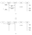
도 14는 레가시 핸드오버 과정을 설명하기 위한 도면이다.
도 15는 mmWave 단말에 대해 빠른 폴백을 위한 초기 접속 상태를 설명하기 위한 도면이다.
도 16은 레가시 시스템에서 수행되는 4단계의 폴백 준비단계가 1 단계의 폴백 준비단계로 수행되는 방법을 설명하기 위한 도면이다.
도 17은 링크 단절을 피하기 위한 빠른 폴백을 수행하는 방법을 설명하기 위한 도면이다.
도 18은 NAS 시그널링과 RRC 연결을 설명하기 위한 계층 구성도의 일례이다.
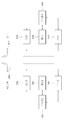
도 19는 빠른 폴백을 수행하는 방법을 설명하기 위한 도면이다.
도 20에서 설명하는 장치는 도 1 내지 도 19에서 설명한 방법들이 구현될 수 있는 수단이다.Are included as a part of the detailed description to facilitate understanding of the present invention, and the accompanying drawings provide various embodiments of the present invention. Further, the accompanying drawings are used to describe embodiments of the present invention in conjunction with the detailed description.
1 is a diagram for explaining a physical channel and a signal transmission method using the same.
2 is a diagram showing an example of the structure of a radio frame.
3 is a diagram illustrating a resource grid for a downlink slot.
4 is a diagram showing an example of the structure of an uplink sub-frame.
5 is a diagram showing an example of the structure of a downlink sub-frame.
6 is a diagram showing a result of linear modeling of path attenuation according to distance.
7 is a diagram for explaining a situation in which an mmWave signal is transmitted in a room.
8 is a diagram showing a case where attenuation of the mmWave signal occurs by a person.
9 is a graph showing a relationship between a change in LoS / NLoS transition time and a received power according to a frequency.
10 is a diagram for indicating that signal detection may fail during operation based on previous CQI feedback due to a change in the mmWave downlink received signal.
11 is a diagram showing received power scenarios for explaining how the mmWave LoS / NLoS transition affects the link environment.
12 is a diagram showing an example of a radio link disconnection process.
13 is a diagram for explaining a method of estimating a situation in which a UE transits from a LoS environment to an NLoS environment, that is, when a NLoS occurs.
14 is a diagram for explaining a legacy handover process.
15 is a diagram for explaining an initial connection state for quick fallback to the mmWave terminal.
16 is a diagram for explaining a method in which a fallback preparation step of four stages performed in a legacy system is performed in a fallback preparation stage of a first stage.
17 is a diagram for explaining a method of performing quick fallback to avoid link disconnection.
18 is an example of a hierarchical diagram for explaining NAS signaling and RRC connection.
19 is a diagram for explaining a method of performing quick fallback.
The apparatus described in Fig. 20 is a means by which the methods described in Figs. 1 to 19 can be implemented.
이하의 실시예들은 본 발명의 구성요소들과 특징들을 소정 형태로 결합한 것들이다. 각 구성요소 또는 특징은 별도의 명시적 언급이 없는 한 선택적인 것으로 고려될 수 있다. 각 구성요소 또는 특징은 다른 구성요소나 특징과 결합되지 않은 형태로 실시될 수 있다. 또한, 일부 구성요소들 및/또는 특징들을 결합하여 본 발명의 실시예를 구성할 수도 있다. 본 발명의 실시예들에서 설명되는 동작들의 순서는 변경될 수 있다. 어느 실시예의 일부 구성이나 특징은 다른 실시예에 포함될 수 있고, 또는 다른 실시예의 대응하는 구성 또는 특징과 교체될 수 있다.The following embodiments are a combination of elements and features of the present invention in a predetermined form. Each component or characteristic may be considered optional unless otherwise expressly stated. Each component or feature may be implemented in a form that is not combined with other components or features. In addition, some of the elements and / or features may be combined to form an embodiment of the present invention. The order of the operations described in the embodiments of the present invention may be changed. Some configurations or features of certain embodiments may be included in other embodiments, or may be replaced with corresponding configurations or features of other embodiments.
도면에 대한 설명에서, 본 발명의 요지를 흐릴 수 있는 절차 또는 단계 등은 기술하지 않았으며, 당업자의 수준에서 이해할 수 있을 정도의 절차 또는 단계는 또한 기술하지 아니하였다.In the description of the drawings, there is no description of procedures or steps that may obscure the gist of the present invention, nor is any description of steps or steps that can be understood by those skilled in the art.
명세서 전체에서, 어떤 부분이 어떤 구성요소를 "포함(comprising 또는 including)"한다고 할 때, 이는 특별히 반대되는 기재가 없는 한 다른 구성요소를 제외하는 것이 아니라 다른 구성요소를 더 포함할 수 있는 것을 의미한다. 또한, 명세서에 기재된 "…부", "…기", "모듈" 등의 용어는 적어도 하나의 기능이나 동작을 처리하는 단위를 의미하며, 이는 하드웨어나 소프트웨어 또는 하드웨어 및 소프트웨어의 결합으로 구현될 수 있다. 또한, "일(a 또는 an)", "하나(one)", "그(the)" 및 유사 관련어는 본 발명을 기술하는 문맥에 있어서(특히, 이하의 청구항의 문맥에서) 본 명세서에 달리 지시되거나 문맥에 의해 분명하게 반박되지 않는 한, 단수 및 복수 모두를 포함하는 의미로 사용될 수 있다.Throughout the specification, when an element is referred to as "comprising" or " including ", it is meant that the element does not exclude other elements, do. Also, the terms " part, "" module," and " module ", etc. in the specification mean a unit for processing at least one function or operation and may be implemented by hardware or software or a combination of hardware and software have. Also, the terms " a or ", "one "," the ", and the like are synonyms in the context of describing the invention (particularly in the context of the following claims) May be used in a sense including both singular and plural, unless the context clearly dictates otherwise.
본 명세서에서 본 발명의 실시예들은 기지국과 이동국 간의 데이터 송수신 관계를 중심으로 설명되었다. 여기서, 기지국은 이동국과 직접적으로 통신을 수행하는 네트워크의 종단 노드(terminal node)로서의 의미가 있다. 본 문서에서 기지국에 의해 수행되는 것으로 설명된 특정 동작은 경우에 따라서는 기지국의 상위 노드(upper node)에 의해 수행될 수도 있다.The embodiments of the present invention have been described herein with reference to a data transmission / reception relationship between a base station and a mobile station. Here, the base station is meaningful as a terminal node of a network that directly communicates with a mobile station. The specific operation described herein as performed by the base station may be performed by an upper node of the base station, as the case may be.
즉, 기지국을 포함하는 다수의 네트워크 노드들(network nodes)로 이루어지는 네트워크에서 이동국과의 통신을 위해 수행되는 다양한 동작들은 기지국 또는 기지국 이외의 다른 네트워크 노드들에 의해 수행될 수 있다. 이때, '기지국'은 고정국(fixed station), Node B, eNode B(eNB), 발전된 기지국(ABS: Advanced Base Station) 또는 억세스 포인트(access point) 등의 용어에 의해 대체될 수 있다.That is, various operations performed for communication with a mobile station in a network consisting of a plurality of network nodes including a base station may be performed by a base station or other network nodes other than the base station. At this time, the 'base station' may be replaced by terms such as a fixed station, a Node B, an eNode B (eNB), an Advanced Base Station (ABS) or an access point.
또한, 본 발명의 실시예들에서 단말(Terminal)은 사용자 기기(UE: User Equipment), 이동국(MS: Mobile Station), 가입자 단말(SS: Subscriber Station), 이동 가입자 단말(MSS: Mobile Subscriber Station), 이동 단말(Mobile Terminal) 또는 발전된 이동단말(AMS: Advanced Mobile Station) 등의 용어로 대체될 수 있다.Also, in the embodiments of the present invention, a terminal may be a user equipment (UE), a mobile station (MS), a subscriber station (SS), a mobile subscriber station (MSS) , A mobile terminal, or an advanced mobile station (AMS).
또한, 송신단은 데이터 서비스 또는 음성 서비스를 제공하는 고정 및/또는 이동 노드를 말하고, 수신단은 데이터 서비스 또는 음성 서비스를 수신하는 고정 및/또는 이동 노드를 의미한다. 따라서, 상향링크에서는 이동국이 송신단이 되고, 기지국이 수신단이 될 수 있다. 마찬가지로, 하향링크에서는 이동국이 수신단이 되고, 기지국이 송신단이 될 수 있다.Also, the transmitting end refers to a fixed and / or mobile node providing data service or voice service, and the receiving end means a fixed and / or mobile node receiving data service or voice service. Therefore, in the uplink, the mobile station may be the transmitting end and the base station may be the receiving end. Similarly, in a downlink, a mobile station may be a receiving end and a base station may be a transmitting end.
본 발명의 실시예들은 무선 접속 시스템들인 IEEE 802.xx 시스템, 3GPP(3rd Generation Partnership Project) 시스템, 3GPP LTE 시스템 및 3GPP2 시스템 중 적어도 하나에 개시된 표준 문서들에 의해 뒷받침될 수 있으며, 특히, 본 발명의 실시예들은 3GPP TS 36.211, 3GPP TS 36.212, 3GPP TS 36.213, 3GPP TS 36.321 및 3GPP TS 36.331 문서들에 의해 뒷받침 될 수 있다. 즉, 본 발명의 실시예들 중 설명하지 않은 자명한 단계들 또는 부분들은 상기 문서들을 참조하여 설명될 수 있다. 또한, 본 문서에서 개시하고 있는 모든 용어들은 상기 표준 문서에 의해 설명될 수 있다.Embodiments of the present invention may be supported by the standard documents disclosed in at least one of the IEEE 802.xx system, the 3rd Generation Partnership Project (3GPP) system, the 3GPP LTE system and the 3GPP2 system, May be supported by the documents 3GPP TS 36.211, 3GPP TS 36.212, 3GPP TS 36.213, 3GPP TS 36.321 and 3GPP TS 36.331. That is, self-explaining steps or parts not described in the embodiments of the present invention can be described with reference to the documents. In addition, all terms disclosed in this document may be described by the standard document.
이하, 본 발명에 따른 바람직한 실시 형태를 첨부된 도면을 참조하여 상세하게 설명한다. 첨부된 도면과 함께 이하에 개시될 상세한 설명은 본 발명의 예시적인 실시형태를 설명하고자 하는 것이며, 본 발명이 실시될 수 있는 유일한 실시형태를 나타내고자 하는 것이 아니다.Hereinafter, preferred embodiments according to the present invention will be described in detail with reference to the accompanying drawings. DETAILED DESCRIPTION OF THE PREFERRED EMBODIMENTS The following detailed description, together with the accompanying drawings, is intended to illustrate exemplary embodiments of the invention and is not intended to represent the only embodiments in which the invention may be practiced.
또한, 본 발명의 실시예들에서 사용되는 특정(特定) 용어들은 본 발명의 이해를 돕기 위해서 제공된 것이며, 이러한 특정 용어의 사용은 본 발명의 기술적 사상을 벗어나지 않는 범위에서 다른 형태로 변경될 수 있다.In addition, the specific terms used in the embodiments of the present invention are provided to facilitate understanding of the present invention, and the use of such specific terms can be changed to other forms without departing from the technical idea of the present invention .
예를 들어, 전송기회구간(TxOP: Transmission Opportunity Period)라는 용어는 전송구간 또는 RRP(Reserved Resource Period)라는 용어와 동일한 의미로 사용될 수 있다. 또한, LBT(Listen Before Talk) 과정은 채널 상태가 유휴인지 여부를 판단하기 위한 캐리어 센싱 과정과 동일한 목적으로 수행될 수 있다.For example, the term Transmission Opportunity Period (TxOP) may be used with the same meaning as the term transmission period or RRP (Reserved Resource Period). Also, the LBT (Listen Before Talk) process can be performed for the same purpose as the carrier sensing process for determining whether the channel state is idle.
이하에서는 본 발명의 실시예들이 사용될 수 있는 무선 접속 시스템의 일례로 3GPP LTE/LTE-A 시스템에 대해서 설명한다.Hereinafter, a 3GPP LTE / LTE-A system will be described as an example of a radio access system in which embodiments of the present invention can be used.
이하의 기술은 CDMA(code division multiple access), FDMA(frequency division multiple access), TDMA(time division multiple access), OFDMA(orthogonal frequency division multiple access), SC-FDMA(single carrier frequency division multiple access) 등과 같은 다양한 무선 접속 시스템에 적용될 수 있다.The following description is to be understood as illustrative and non-limiting, such as code division multiple access (CDMA), frequency division multiple access (FDMA), time division multiple access (TDMA), orthogonal frequency division multiple access (OFDMA), single carrier frequency division multiple access And can be applied to various wireless connection systems.
CDMA는 UTRA(Universal Terrestrial Radio Access)나 CDMA2000과 같은 무선 기술(radio technology)로 구현될 수 있다. TDMA는 GSM(Global System for Mobile communications)/GPRS(General Packet Radio Service)/EDGE(Enhanced Data Rates for GSM Evolution)와 같은 무선 기술로 구현될 수 있다. OFDMA는 IEEE 802.11 (Wi-Fi), IEEE 802.16 (WiMAX), IEEE 802-20, E-UTRA(Evolved UTRA) 등과 같은 무선 기술로 구현될 수 있다.CDMA may be implemented in radio technology such as Universal Terrestrial Radio Access (UTRA) or CDMA2000. The TDMA may be implemented in a wireless technology such as Global System for Mobile communications (GSM) / General Packet Radio Service (GPRS) / Enhanced Data Rates for GSM Evolution (EDGE). OFDMA may be implemented in wireless technologies such as IEEE 802.11 (Wi-Fi), IEEE 802.16 (WiMAX), IEEE 802-20, and Evolved UTRA (E-UTRA).
UTRA는 UMTS(Universal Mobile Telecommunications System)의 일부이다. 3GPP LTE(Long Term Evolution)은 E-UTRA를 사용하는 E-UMTS(Evolved UMTS)의 일부로써, 하향링크에서 OFDMA를 채용하고 상향링크에서 SC-FDMA를 채용한다. LTE-A(Advanced) 시스템은 3GPP LTE 시스템이 개량된 시스템이다. 본 발명의 기술적 특징에 대한 설명을 명확하게 하기 위해, 본 발명의 실시예들을 3GPP LTE/LTE-A 시스템을 위주로 기술하지만 IEEE 802.16e/m 시스템 등에도 적용될 수 있다.UTRA is part of the Universal Mobile Telecommunications System (UMTS). 3GPP Long Term Evolution (LTE) is a part of E-UMTS (Evolved UMTS) using E-UTRA, adopting OFDMA in downlink and SC-FDMA in uplink. The LTE-A (Advanced) system is an improved 3GPP LTE system. In order to clarify the technical features of the present invention, the embodiments of the present invention are described mainly in the 3GPP LTE / LTE-A system, but can also be applied to the IEEE 802.16e / m system and the like.
1. 3GPP LTE/LTE_A 시스템1. 3GPP LTE / LTE_A system
무선 접속 시스템에서 단말은 하향링크(DL: Downlink)를 통해 기지국으로부터 정보를 수신하고, 상향링크(UL: Uplink)를 통해 기지국으로 정보를 전송한다. 기지국과 단말이 송수신하는 정보는 일반 데이터 정보 및 다양한 제어 정보를 포함하고, 이들이 송수신 하는 정보의 종류/용도에 따라 다양한 물리 채널이 존재한다.In a wireless access system, a terminal receives information from a base station through a downlink (DL) and transmits information to a base station through an uplink (UL). The information transmitted and received between the base station and the terminal includes general data information and various control information, and there are various physical channels depending on the type / use of the information transmitted / received.
1.1 시스템 일반1.1 System General
도 1은 본 발명의 실시예들에서 사용될 수 있는 물리 채널들 및 이들을 이용한 신호 전송 방법을 설명하기 위한 도면이다.FIG. 1 is a view for explaining physical channels that can be used in embodiments of the present invention and a signal transmission method using the same.
전원이 꺼진 상태에서 다시 전원이 켜지거나, 새로이 셀에 진입한 단말은 S11 단계에서 기지국과 동기를 맞추는 등의 초기 셀 탐색 (Initial cell search) 작업을 수행한다. 이를 위해 단말은 기지국으로부터 주동기 채널 (P-SCH: Primary Synchronization Channel) 및 부동기 채널 (S-SCH: Secondary Synchronization Channel)을 수신하여 기지국과 동기를 맞추고, 셀 ID 등의 정보를 획득한다.The terminal that is powered on again after power is turned off or a terminal that has entered a new cell performs an initial cell search operation such as synchronizing with the base station in step S11. To this end, a mobile station receives a primary synchronization channel (P-SCH) and a secondary synchronization channel (S-SCH) from a base station, synchronizes with the base station, and acquires information such as a cell ID.
그 후, 단말은 기지국으로부터 물리방송채널 (PBCH: Physical Broadcast Channel) 신호를 수신하여 셀 내 방송 정보를 획득할 수 있다.Then, the terminal can receive the physical broadcast channel (PBCH) signal from the base station and acquire the in-cell broadcast information.
한편, 단말은 초기 셀 탐색 단계에서 하향링크 참조 신호 (DL RS: Downlink Reference Signal)를 수신하여 하향링크 채널 상태를 확인할 수 있다.Meanwhile, the UE can receive the downlink reference signal (DL RS) in the initial cell search step to check the downlink channel state.
초기 셀 탐색을 마친 단말은 S12 단계에서 물리하향링크제어채널 (PDCCH: Physical Downlink Control Channel) 및 물리하향링크제어채널 정보에 따른 물리하향링크공유 채널 (PDSCH: Physical Downlink Control Channel)을 수신하여 조금 더 구체적인 시스템 정보를 획득할 수 있다.Upon completion of the initial cell search, the UE receives a physical downlink control channel (PDCCH) and a physical downlink control channel (PDSCH) according to physical downlink control channel information in step S12, Specific system information can be obtained.
이후, 단말은 기지국에 접속을 완료하기 위해 이후 단계 S13 내지 단계 S16과 같은 임의 접속 과정 (Random Access Procedure)을 수행할 수 있다. 이를 위해 단말은 물리임의접속채널 (PRACH: Physical Random Access Channel)을 통해 프리앰블 (preamble)을 전송하고(S13), 물리하향링크제어채널 및 이에 대응하는 물리하향링크공유 채널을 통해 프리앰블에 대한 응답 메시지를 수신할 수 있다(S14). 경쟁 기반 임의 접속의 경우, 단말은 추가적인 물리임의접속채널 신호의 전송(S15) 및 물리하향링크제어채널 신호 및 이에 대응하는 물리하향링크공유 채널 신호의 수신(S16)과 같은 충돌해결절차 (Contention Resolution Procedure)를 수행할 수 있다.Thereafter, the terminal may perform a random access procedure such as steps S13 to S16 to complete the connection to the base station. To this end, the UE transmits a preamble through a Physical Random Access Channel (PRACH) (S13), and transmits a response message to the preamble through the physical downlink control channel and the corresponding physical downlink shared channel (S14). In the case of a contention-based random access, the UE transmits a physical random access channel signal (S15) and a Contention Resolution procedure (S16) such as a physical downlink control channel signal and a corresponding physical downlink shared channel signal Procedure can be performed.
상술한 바와 같은 절차를 수행한 단말은 이후 일반적인 상/하향링크 신호 전송 절차로서 물리하향링크제어채널 신호 및/또는 물리하향링크공유채널 신호의 수신(S17) 및 물리상향링크공유채널 (PUSCH: Physical Uplink Shared Channel) 신호 및/또는 물리상향링크제어채널 (PUCCH: Physical Uplink Control Channel) 신호의 전송(S18)을 수행할 수 있다.The UE having performed the procedure described above transmits a physical downlink control channel signal and / or physical downlink shared channel signal (S17) and a physical uplink shared channel (PUSCH: physical (S18) of an uplink shared channel (PUCCH) signal and / or a physical uplink control channel (PUCCH) signal.
단말이 기지국으로 전송하는 제어정보를 통칭하여 상향링크 제어정보(UCI: Uplink Control Information)라고 지칭한다. UCI는 HARQ-ACK/NACK (Hybrid Automatic Repeat and reQuest Acknowledgement/Negative-ACK), SR (Scheduling Request), CQI (Channel Quality Indication), PMI (Precoding Matrix Indication), RI (Rank Indication) 정보 등을 포함한다.Control information transmitted from the UE to the Node B is collectively referred to as uplink control information (UCI). The UCI includes HARQ-ACK / NACK (Hybrid Automatic Repeat and Request Acknowledgment / Negative-ACK), SR (Scheduling Request), CQI (Channel Quality Indication), PMI (Precoding Matrix Indication) .
LTE 시스템에서 UCI는 일반적으로 PUCCH를 통해 주기적으로 전송되지만, 제어정보와 트래픽 데이터가 동시에 전송되어야 할 경우 PUSCH를 통해 전송될 수 있다. 또한, 네트워크의 요청/지시에 의해 PUSCH를 통해 UCI를 비주기적으로 전송할 수 있다.In the LTE system, the UCI is periodically transmitted through the PUCCH in general, but may be transmitted through the PUSCH when the control information and the traffic data are to be simultaneously transmitted. In addition, UCI can be transmitted non-periodically through the PUSCH according to the request / instruction of the network.
도 2는 본 발명의 실시예들에서 사용되는 무선 프레임의 구조를 나타낸다.2 shows a structure of a radio frame used in embodiments of the present invention.
도 2(a)는 타입 1 프레임 구조(frame structure type 1)를 나타낸다. 타입 1 프레임 구조는 전이중(full duplex) FDD(Frequency Division Duplex) 시스템과 반이중(half duplex) FDD 시스템 모두에 적용될 수 있다.2 (a) shows a
하나의 무선 프레임(radio frame)은 Tf = 307200*Ts = 10ms의 길이를 가지고, Tslot = 15360*Ts = 0.5ms의 균등한 길이를 가지며 0부터 19의 인덱스가 부여된 20개의 슬롯으로 구성된다. 하나의 서브프레임은 2개의 연속된 슬롯으로 정의되며, i 번째 서브프레임은 2i 와 2i+1에 해당하는 슬롯으로 구성된다. 즉, 무선 프레임(radio frame)은 10개의 서브프레임(subframe)으로 구성된다. 하나의 서브프레임을 전송하는 데 걸리는 시간을 TTI(transmission time interval)이라 한다. 여기서, Ts 는 샘플링 시간을 나타내고, Ts=1/(15kHz×2048)=3.2552×10-8(약 33ns)로 표시된다. 슬롯은 시간 영역에서 복수의 OFDM 심볼 또는 SC-FDMA 심볼을 포함하고, 주파수 영역에서 복수의 자원블록(Resource Block)을 포함한다.One radio frame is composed of 20 slots having a length of Tf = 307200 * Ts = 10ms, an equal length of Tslot = 15360 * Ts = 0.5ms, and indexes of 0 to 19. One subframe is defined as two consecutive slots, and the i-th subframe consists of slots corresponding to 2i and 2i + 1. That is, a radio frame is composed of 10 subframes. The time required to transmit one subframe is referred to as a transmission time interval (TTI). Here, Ts represents the sampling time, and is represented by Ts = 1 / (15 kHz x 2048) = 3.2552 x 10⁻⁸ (about 33 ns). A slot includes a plurality of OFDM symbols or SC-FDMA symbols in a time domain, and a plurality of resource blocks in a frequency domain.
하나의 슬롯은 시간 영역에서 복수의 OFDM(orthogonal frequency division multiplexing) 심볼을 포함한다. 3GPP LTE는 하향링크에서 OFDMA를 사용하므로 OFDM 심볼은 하나의 심볼 구간(symbol period)을 표현하기 위한 것이다. OFDM 심볼은 하나의 SC-FDMA 심볼 또는 심볼 구간이라고 할 수 있다. 자원 블록(resource block)은 자원 할당 단위이고, 하나의 슬롯에서 복수의 연속적인 부반송파(subcarrier)를 포함한다.One slot includes a plurality of orthogonal frequency division multiplexing (OFDM) symbols in the time domain. Since 3GPP LTE uses OFDMA in the downlink, an OFDM symbol is intended to represent one symbol period. The OFDM symbol may be one SC-FDMA symbol or a symbol interval. A resource block is a resource allocation unit and includes a plurality of consecutive subcarriers in one slot.
전이중 FDD 시스템에서는 각 10ms 구간 동안 10개의 서브프레임은 하향링크 전송과 상향링크 전송을 위해 동시에 이용될 수 있다. 이때, 상향링크와 하향링크 전송은 주파수 영역에서 분리된다. 반면, 반이중 FDD 시스템의 경우 단말은 전송과 수신을 동시에 할 수 없다.In a full-duplex FDD system, 10 subframes can be used simultaneously for downlink transmission and uplink transmission for each 10 ms interval. At this time, the uplink and downlink transmissions are separated in the frequency domain. On the other hand, in the case of a half-duplex FDD system, the UE can not transmit and receive simultaneously.
상술한 무선 프레임의 구조는 하나의 예시에 불과하며, 무선 프레임에 포함되는 서브 프레임의 수 또는 서브 프레임에 포함되는 슬롯의 수, 슬롯에 포함되는 OFDM 심볼의 수는 다양하게 변경될 수 있다.The structure of the radio frame is merely an example, and the number of subframes included in a radio frame, the number of slots included in a subframe, and the number of OFDM symbols included in a slot can be variously changed.
도 2(b)는 타입 2 프레임 구조(frame structure type 2)를 나타낸다. 타입 2 프레임 구조는 TDD 시스템에 적용된다. 하나의 무선 프레임(radio frame)은 Tf = 307200*Ts = 10ms의 길이를 가지며, 153600*Ts = 5ms 길이를 가지는 2개의 하프프레임(half-frame)으로 구성된다. 각 하프프레임은 30720*Ts = 1ms의 길이를 가지는 5개의 서브프레임으로 구성된다. i 번째 서브프레임은 2i 와 2i+1에 해당하는 각 Tslot = 15360*Ts = 0.5ms의 길이를 가지는 2개의 슬롯으로 구성된다. 여기에서, Ts 는 샘플링 시간을 나타내고, Ts=1/(15kHz×2048)=3.2552×10-8(약 33ns)로 표시된다. 2 (b) shows a
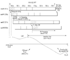
타입 2 프레임에는 DwPTS(Downlink Pilot Time Slot), 보호구간(GP: Guard Period), UpPTS(Uplink Pilot Time Slot)인 3가지의 필드로 구성되는 특별 서브프레임을 포함한다. 여기서, DwPTS는 단말에서의 초기 셀 탐색, 동기화 또는 채널 추정에 사용된다. UpPTS는 기지국에서의 채널 추정과 단말의 상향 전송 동기를 맞추는 데 사용된다. 보호구간은 상향링크와 하향링크 사이에 하향링크 신호의 다중경로 지연으로 인해 상향링크에서 생기는 간섭을 제거하기 위한 구간이다. The
다음 표 1는 특별 프레임의 구성(DwPTS/GP/UpPTS의 길이)을 나타낸다.Table 1 below shows the composition of the special frame (DwPTS / GP / UpPTS length).

도 3은 본 발명의 실시예들에서 사용될 수 있는 하향링크 슬롯에 대한 자원 그리드(resource grid)를 예시한 도면이다.3 is a diagram illustrating a resource grid for a downlink slot that may be used in embodiments of the present invention.
도 3을 참조하면, 하나의 하향링크 슬롯은 시간 영역에서 복수의 OFDM 심볼을 포함한다. 여기서, 하나의 하향링크 슬롯은 7개의 OFDM 심볼을 포함하고, 하나의 자원 블록은 주파수 영역에서 12개의 부 반송파를 포함하는 것을 예시적으로 기술하나, 이에 한정되는 것은 아니다.Referring to FIG. 3, one downlink slot includes a plurality of OFDM symbols in a time domain. Herein, one downlink slot includes 7 OFDM symbols, and one resource block includes 12 subcarriers in the frequency domain. However, the present invention is not limited thereto.
자원 그리드 상에서 각 요소(element)를 자원 요소(resource element)하고, 하나의 자원 블록은 12 × 7 개의 자원 요소를 포함한다. 하향링크 슬롯에 포함되는 자원 블록들의 수 NDL은 하향링크 전송 대역폭(bandwidth)에 종속한다. 상향링크 슬롯의 구조는 하향링크 슬롯의 구조와 동일할 수 있다.Each element on the resource grid is a resource element, and one resource block contains 12 × 7 resource elements. The number of resource blocks NDL included in the downlink slot is dependent on the downlink transmission bandwidth. The structure of the uplink slot may be the same as the structure of the downlink slot.
도 4는 본 발명의 실시예들에서 사용될 수 있는 상향링크 서브 프레임의 구조를 나타낸다.4 illustrates a structure of an uplink subframe that can be used in embodiments of the present invention.
도 4를 참조하면, 상향링크 서브 프레임은 주파수 영역에서 제어 영역과 데이터 영역으로 나눌 수 있다. 제어 영역에는 상향링크 제어 정보를 나르는 PUCCH가 할당된다. 데이터 영역은 사용자 데이터를 나르는 PUSCH가 할당된다. 단일 반송파 특성을 유지하기 위해 하나의 단말은 PUCCH와 PUSCH를 동시에 전송하지 않는다. 하나의 단말에 대한 PUCCH에는 서브 프레임 내에 RB 쌍이 할당된다. RB 쌍에 속하는 RB들은 2개의 슬롯들의 각각에서 서로 다른 부 반송파를 차지한다. 이러한 PUCCH에 할당된 RB 쌍은 슬롯 경계(slot boundary)에서 주파수 도약(frequency hopping)된다고 한다.Referring to FIG. 4, the uplink subframe can be divided into a control region and a data region in the frequency domain. A PUCCH for carrying UL control information is allocated to the control region. The data area is assigned a PUSCH carrying user data. To maintain a single carrier characteristic, one UE does not transmit PUCCH and PUSCH at the same time. An RB pair is allocated to a PUCCH for one UE in a subframe. RBs belonging to the RB pair occupy different subcarriers in each of the two slots. It is assumed that the RB pair assigned to the PUCCH is frequency hopped at the slot boundary.
도 5는 본 발명의 실시예들에서 사용될 수 있는 하향링크 서브 프레임의 구조를 나타낸다.5 shows a structure of a downlink subframe that can be used in embodiments of the present invention.
도 5를 참조하면, 서브 프레임내의 첫번째 슬롯에서 OFDM 심볼 인덱스 0부터 최대 3개의 OFDM 심볼들이 제어 채널들이 할당되는 제어 영역(control region)이고, 나머지 OFDM 심볼들은 PDSCH이 할당되는 데이터 영역(data region)이다. 3GPP LTE에서 사용되는 하향링크 제어 채널의 일례로 PCFICH(Physical Control Format Indicator Channel), PDCCH, PHICH(Physical Hybrid-ARQ Indicator Channel) 등이 있다.Referring to FIG. 5, a control region in which control channels are allocated to a maximum of three OFDM symbols starting from an
PCFICH는 서브 프레임의 첫 번째 OFDM 심볼에서 전송되고, 서브 프레임 내에 제어 채널들의 전송을 위하여 사용되는 OFDM 심볼들의 수(즉, 제어 영역의 크기)에 관한 정보를 나른다. PHICH는 상향 링크에 대한 응답 채널이고, HARQ(Hybrid Automatic Repeat Request)에 대한 ACK(Acknowledgement)/NACK(Negative-Acknowledgement) 신호를 나른다. PDCCH를 통해 전송되는 제어 정보를 하향링크 제어정보(DCI: downlink control information)라고 한다. 하향링크 제어정보는 상향링크 자원 할당 정보, 하향링크 자원 할당 정보 또는 임의의 단말 그룹에 대한 상향링크 전송(Tx) 파워 제어 명령을 포함한다.The PCFICH is carried in the first OFDM symbol of the subframe and carries information about the number of OFDM symbols (i.e., the size of the control region) used for transmission of control channels in the subframe. The PHICH is a response channel for the uplink and carries an ACK (Acknowledgment) / NACK (Negative-Acknowledgment) signal for HARQ (Hybrid Automatic Repeat Request). The control information transmitted through the PDCCH is referred to as downlink control information (DCI). The downlink control information includes uplink resource allocation information, downlink resource allocation information, or an uplink transmission (Tx) power control command for an arbitrary terminal group.
1.2 PDCCH(Physical Downlink Control Channel)1.2 PDCCH (Physical Downlink Control Channel)
1.2.1 PDCCH 일반1.2.1 PDCCH General
PDCCH는 DL-SCH(Downlink Shared Channel)의 자원 할당 및 전송 포맷(즉, 하향링크 그랜트(DL-Grant)), UL-SCH(Uplink Shared Channel)의 자원 할당 정보(즉, 상향링크 그랜트(UL-Grant)), PCH(Paging Channel)에서의 페이징(paging) 정보, DL-SCH에서의 시스템 정보, PDSCH에서 전송되는 랜덤 액세스 응답(random access response)과 같은 상위 레이어(upper-layer) 제어 메시지에 대한 자원 할당, 임의의 단말 그룹 내 개별 단말들에 대한 전송 파워 제어 명령들의 집합, VoIP(Voice over IP)의 활성화 여부에 관한 정보 등을 나를 수 있다.The PDCCH includes resource allocation information of uplink shared channel (DL-SCH) (i.e., downlink grant (DL-Grant), UL-SCH (uplink shared channel) Layer control message, such as paging information in the Paging Channel (PCH), system information in the DL-SCH, and a random access response transmitted on the PDSCH, Resource allocation, a set of transmission power control commands for individual terminals in an arbitrary terminal group, information on whether to activate Voice over IP (VoIP), and the like.
복수의 PDCCH가 제어영역 내에서 전송될 수 있으며, 단말은 복수의 PDCCH를 모니터링할 수 있다. PDCCH는 하나 또는 몇몇 연속적인 CCE(control channel elements)의 집합(aggregation)으로 구성된다. 하나 또는 몇몇 연속적인 CCE의 집합으로 구성된 PDCCH는 서브블록 인터리빙(subblock interleaving)을 거친 후에 제어 영역을 통해 전송될 수 있다. CCE는 무선채널의 상태에 따른 부호화율을 PDCCH에게 제공하기 위해 사용되는 논리적 할당 단위이다. CCE는 복수의 자원 요소 그룹(REG: resource element group)에 대응된다. CCE의 수와 CCE들에 의해 제공되는 부호화율의 연관 관계에 따라 PDCCH의 포맷 및 가능한 PDCCH의 비트수가 결정된다A plurality of PDCCHs can be transmitted in the control domain, and the UE can monitor a plurality of PDCCHs. The PDCCH consists of one or several consecutive aggregation of control channel elements (CCEs). A PDCCH composed of a set of one or several consecutive CCEs can be transmitted through the control domain after subblock interleaving. The CCE is a logical allocation unit used to provide the PDCCH with the coding rate according to the state of the radio channel. The CCE corresponds to a plurality of resource element groups (REGs). The format of the PDCCH and the number of bits of the possible PDCCH are determined according to the relationship between the number of CCEs and the coding rate provided by the CCEs
1.2.2 PDCCH 구조1.2.2 PDCCH structure
복수의 단말에 대한 다중화된 복수의 PDCCH가 제어영역 내에서 전송될 수 있다. PDCCH는 하나 또는 2 이상의 연속적인 CCE의 집합(CCE aggregation)으로 구성된다. CCE는 4개의 자원 요소로 구성된 REG의 9개의 세트에 대응하는 단위를 말한다. 각 REG에는 4개의 QPSK(Quadrature Phase Shift Keying) 심볼이 매핑 된다. 참조 신호(RS: Reference Signal)에 의하여 점유된 자원 요소들은 REG에 포함되지 않는다. 즉, OFDM 심볼 내에서 REG의 총 개수는 셀 특정 참조 신호가 존재하는지 여부에 따라 달라질 수 있다. 4개의 자원 요소를 하나의 그룹에 매핑하는 REG의 개념은 다른 하향링크 제어 채널(예를 들어, PCFICH 또는 PHICH)에도 적용될 수 있다. PCFICH 또는 PHICH에 할당되지 않는 REG를 NREG라 하면 시스템에서 이용 가능한 CCE의 개수는 NCCE = floor(NREG/9)이며, 각 CCE는 0부터 NCCE-1 까지 인덱스를 가진다.A plurality of multiplexed PDCCHs for a plurality of terminals can be transmitted in the control region. The PDCCH consists of one or two or more consecutive CCE aggregations. A CCE is a unit corresponding to nine sets of REGs composed of four resource elements. Each REG is mapped to four quadrature phase shift keying (QPSK) symbols. Resource elements occupied by a reference signal (RS) are not included in the REG. That is, the total number of REGs in an OFDM symbol may vary depending on whether a cell specific reference signal is present or not. The concept of a REG mapping four resource elements to one group can be applied to other downlink control channels (e.g., PCFICH or PHICH). If REG not assigned to PCFICH or PHICH is N REG , the number of CCEs available in the system is N CCE = floor (N REG / 9), and each CCE has an index from 0 to N CCE -1.
단말의 디코딩 프로세스를 단순화하기 위해서, n개의 CCE를 포함하는 PDCCH 포맷은 n의 배수와 동일한 인덱스를 가지는 CCE부터 시작될 수 있다. 즉, CCE 인덱스가 i인 경우 imod(n) = 0 을 만족하는 CCE부터 시작될 수 있다.In order to simplify the decoding process of the UE, the PDCCH format including n CCEs can be started from a CCE having the same index as a multiple of n. That is, if the CCE index is i, it can be started from a CCE satisfying imod (n) = 0.
기지국은 하나의 PDCCH 신호를 구성하기 위해 {1, 2, 4, 8} 개의 CCE들을 사용할 수 있으며, 이때의 {1, 2, 4, 8}은 CCE 집합 레벨(aggregation level)이라고 부른다. 특정 PDCCH의 전송을 위해 사용되는 CCE의 개수는 채널 상태에서 따라 기지국에 의하여 결정된다. 예를 들어, 양호한 하향링크 채널 상태(기지국에 가까운 경우)를 가지는 단말을 위한 PDCCH는 하나의 CCE만으로 충분할 수 있다. 반면, 좋지 않은 채널 상태(셀 경계에 있는 경우)를 가지는 단말의 경우는 8개의 CCE들이 충분한 강인함(robustness)을 위하여 요구될 수 있다. 게다가, PDCCH의 파워 레벨도 채널 상태에 매칭되어 조절될 수 있다.The base station can use {1, 2, 4, 8} CCEs to construct one PDCCH signal, and {1, 2, 4, 8} at this time is called the CCE aggregation level. The number of CCEs used for transmission of a specific PDCCH is determined by the BS according to the channel state. For example, only one CCE may be sufficient for a PDCCH for a UE having a good downlink channel state (when it is close to a base station). On the other hand, in the case of a terminal having a bad channel condition (in the cell boundary), eight CCEs may be required for sufficient robustness. In addition, the power level of the PDCCH can be adjusted to match the channel state.
다음 표 2는 PDCCH 포맷을 나타내며, CCE 집합 레벨에 따라 표 2과 같이 4가지의 PDCCH 포맷이 지원된다.Table 2 below shows the PDCCH format. Four PDCCH formats are supported according to the CCE aggregation level as shown in Table 2 below.
단말마다 CCE 집합 레벨이 다른 이유는 PDCCH에 실리는 제어정보의 포맷 또는 MCS(Modulation and Coding Scheme) 레벨이 다르기 때문이다. MCS 레벨은 데이터 코딩에 사용되는 코드 레이트(code rate)와 변조 차수(modulation order)를 의미한다. 적응적인 MCS 레벨은 링크 적응(link adaptation)을 위해 사용된다. 일반적으로 제어정보를 전송하는 제어채널에서는 3~4개 정도의 MCS 레벨을 고려할 수 있다.The reason why the CCE aggregation level differs from terminal to terminal is that the format of the control information carried on the PDCCH or the Modulation and Coding Scheme (MCS) level is different. The MCS level refers to a code rate and a modulation order used for data coding. The adaptive MCS level is used for link adaptation. In general, three to four MCS levels can be considered in a control channel for transmitting control information.
제어정보의 포맷을 설명하면, PDCCH를 통해 전송되는 제어정보를 하향링크 제어정보(DCI)라고 한다. DCI 포맷에 따라 PDCCH 페이로드(payload)에 실리는 정보의 구성이 달라질 수 있다. PDCCH 페이로드는 정보 비트(information bit)를 의미한다. 다음 표 3은 DCI 포맷에 따른 DCI를 나타낸다. Describing the format of the control information, the control information transmitted through the PDCCH is referred to as downlink control information (DCI). The configuration of the information carried in the PDCCH payload may vary depending on the DCI format. The PDCCH payload means an information bit. Table 3 below shows the DCI according to the DCI format.
표 3을 참조하면, DCI 포맷으로는 PUSCH 스케줄링을 위한 포맷 0, 하나의 PDSCH 코드워드의 스케줄링을 위한 포맷 1, 하나의 PDSCH 코드워드의 간단한(compact) 스케줄링을 위한 포맷 1A, DL-SCH의 매우 간단한 스케줄링을 위한 포맷 1C, 폐루프(Closed-loop) 공간 다중화(spatial multiplexing) 모드에서 PDSCH 스케줄링을 위한 포맷 2, 개루프(Openloop) 공간 다중화 모드에서 PDSCH 스케줄링을 위한 포맷 2A, 상향링크 채널을 위한 TPC(Transmission Power Control) 명령의 전송을 위한 포맷 3 및 3A가 있다. DCI 포맷 1A는 단말에 어떤 전송 모드가 설정되어도 PDSCH 스케줄링을 위해 사용될 수 있다.Referring to Table 3, in the DCI format,
DCI 포맷에 따라 PDCCH 페이로드 길이가 달라질 수 있다. 또, PDCCH 페이로드의 종류와 그에 따른 길이는 간단한(compact) 스케줄링인지 여부 또는 단말에 설정된 전송 모드(transmission mode) 등에 의해 달라질 수 있다.The PDCCH payload length may vary depending on the DCI format. In addition, the type of the PDCCH payload and the length thereof may vary depending on whether it is a compact scheduling or a transmission mode set in the UE.
전송 모드는 단말이 PDSCH를 통한 하향링크 데이터를 수신하기 위해 설정(configuration)될 수 있다. 예를 들어, PDSCH를 통한 하향링크 데이터는 단말에 대한 스케줄된 데이터(scheduled data), 페이징, 랜덤 액세스 응답 또는 BCCH를 통한 브로드캐스트 정보 등이 있다. PDSCH를 통한 하향링크 데이터는 PDCCH를 통해 시그널되는 DCI 포맷과 관계가 있다. 전송 모드는 상위 계층 시그널링(예를 들어, RRC(Radio Resource Control) 시그널링)을 통해 단말에 반정적으로(semi-statically) 설정될 수 있다. 전송 모드는 싱글 안테나 전송(Single antenna transmission) 또는 멀티 안테나(Multi-antenna) 전송으로 구분할 수 있다.The transmission mode may be configured such that the UE receives downlink data over the PDSCH. For example, downlink data on the PDSCH includes scheduled data for the UE, paging, random access response, or broadcast information on the BCCH. The downlink data over the PDSCH is related to the DCI format signaled via the PDCCH. The transmission mode may be semi-statically set to the terminal via higher layer signaling (e.g., Radio Resource Control (RRC) signaling). The transmission mode can be classified into a single antenna transmission or a multi-antenna transmission.
단말은 상위 계층 시그널링을 통해 반정적(semi-static)으로 전송 모드가 설정된다. 예를 들어, 멀티 안테나 전송에는 전송 다이버시티(Transmit diversity), 개루프(Open-loop) 또는 폐루프(Closed-loop) 공간 다중화(Spatial multiplexing), MU-MIMO(Multi-user-Multiple Input Multiple Output) 또는 빔 형성(Beamforming) 등이 있다. 전송 다이버시티는 다중 송신 안테나에서 동일한 데이터를 전송하여 전송 신뢰도를 높이는 기술이다. 공간 다중화는 다중 송신 안테나에서 서로 다른 데이터를 동시에 전송하여 시스템의 대역폭을 증가시키지 않고 고속의 데이터를 전송할 수 있는 기술이다. 빔 형성은 다중 안테나에서 채널 상태에 따른 가중치를 가하여 신호의 SINR(Signal to Interference plus Noise Ratio)을 증가시키는 기술이다.A terminal is set to a semi-static transmission mode through upper layer signaling. For example, transmission diversity, open-loop or closed-loop spatial multiplexing, multi-user-multiple-input multiple output (MU-MIMO) ) Or beam forming (Beamforming). Transmit diversity is a technique for increasing transmission reliability by transmitting the same data in multiple transmit antennas. Spatial multiplexing is a technique capable of transmitting high-speed data without increasing the bandwidth of the system by simultaneously transmitting different data from multiple transmit antennas. Beamforming is a technique for increasing the SINR (Signal to Interference plus Noise Ratio) of a signal by applying a weight according to channel conditions in multiple antennas.
DCI 포맷은 단말에 설정된 전송 모드에 종속된다(depend on). 단말은 자신에게 설정된 전송 모드에 따라 모니터링하는 참조(Reference) DCI 포맷이 있다. 단말에 설정되는 전송 모드는 다음과 같이 10개의 전송 모드를 가질 수 있다.The DCI format is dependent on the transmission mode set in the UE. The UE has a reference DCI format for monitoring according to the transmission mode set for the UE. The transmission mode set in the UE can have 10 transmission modes as follows.
(1) 전송모드 1: 단일 안테나 포트; 포트 0(1) Transmission mode 1: Single antenna port;
(2) 전송모드 2: 전송 다이버시티(Transmit Diversity)(2) Transmission Mode 2: Transmit Diversity [
(3) 전송모드 3: 개루프 공간 다중화 (Open-loop Spatial Multiplexing)(3) Transmission mode 3: Open-loop Spatial Multiplexing
(4) 전송모드 4: 폐루프 공간 다중화 (Closed-loop Spatial Multiplexing)(4) Transmission mode 4: Closed-loop Spatial Multiplexing
(5) 전송모드 5: 다중 사용자 MIMO(5) Transmission mode 5: Multi-user MIMO
(6) 전송모드 6: 폐루프, 랭크 = 1 프리코딩(6) Transmission mode 6: closed loop, rank = 1 precoding
(7) 전송모드 7: 코드북에 기반하지 않는, 단일 레이어 전송을 지원하는 프리코딩(7) Transmission mode 7: Precoding to support single layer transmission, not based on codebook
(8) 전송모드 8: 코드북에 기반하지 않는, 두 개까지 레이어를 지원하는 프리코딩(8) Transmission mode 8: Precoding that supports up to two layers, not based on a codebook
(9) 전송모드 9: 코드북에 기반하지 않는, 여덟 개까지 레이어를 지원하는 프리코딩(9) Transmission mode 9: Precoding that supports up to eight layers, not based on a codebook
(10) 전송모드 10: 코드북에 기반하지 않는, CoMP를 위해 사용되는, 여덟 개까지 레이어를 지원하는 프리코딩(10) Transmission mode 10: Precoding supporting up to eight layers, used for CoMP, not based on codebooks
1.2.3 PDCCH 전송1.2.3 PDCCH transmission
기지국은 단말에게 전송하려는 DCI에 따라 PDCCH 포맷을 결정하고, 제어 정보에 CRC(Cyclic Redundancy Check)를 붙인다. CRC에는 PDCCH의 소유자(owner)나 용도에 따라 고유한 식별자(예를 들어, RNTI(Radio Network Temporary Identifier))가 마스킹된다. 특정의 단말을 위한 PDCCH라면 단말의 고유한 식별자(예를 들어, C-RNTI(Cell-RNTI))가 CRC에 마스킹될 수 있다. 또는 페이징 메시지를 위한 PDCCH라면 페이징 지시 식별자(예를 들어, P-RNTI(Paging-RNTI))가 CRC에 마스킹될 수 있다. 시스템 정보, 더욱 구체적으로 시스템 정보 블록(SIB: System Information Block)를 위한 PDCCH라면 시스템 정보 식별자(예를 들어, SI-RNTI(System Information RNTI))가 CRC에 마스킹될 수 있다. 단말의 랜덤 액세스 프리앰블의 전송에 대한 응답인 랜덤 액세스 응답을 지시하기 위하여 RA-RNTI(random access-RNTI)가 CRC에 마스킹될 수 있다.The base station determines the PDCCH format according to the DCI to be transmitted to the UE, and attaches a CRC (Cyclic Redundancy Check) to the control information. The CRC is masked with a unique identifier (e.g., Radio Network Temporary Identifier (RNTI)) according to the owner or use of the PDCCH. A unique identifier (e.g., C-RNTI (Cell-RNTI)) of the UE may be masked in the CRC if it is a PDCCH for a particular UE. Or a PDCCH for a paging message, a paging indication identifier (e.g., P-RNTI (P-RNTI)) may be masked to the CRC. System information identifiers (e.g., System Information RNTIs) may be masked in the CRC if the PDCCH is for a system information, more specifically a System Information Block (SIB). A random access-RNTI (RA-RNTI) may be masked in the CRC to indicate a random access response that is a response to the transmission of the UE's random access preamble.
이어, 기지국은 CRC가 부가된 제어정보를 채널 코딩을 수행하여 부호화된 데이터(coded data)를 생성한다. 이때, MCS 레벨에 따른 코드 레이트로 채널 코딩을 수행할 수 있다. 기지국은 PDCCH 포맷에 할당된 CCE 집합 레벨에 따른 전송률 매칭(rate matching)을 수행하고, 부호화된 데이터를 변조하여 변조 심볼들을 생성한다. 이때, MCS 레벨에 따른 변조 서열을 사용할 수 있다. 하나의 PDCCH를 구성하는 변조 심볼들은 CCE 집합 레벨이 1, 2, 4, 8 중 하나일 수 있다. 이후, 기지국은 변조 심볼들을 물리적인 자원요소에 맵핑(CCE to RE mapping)한다.Then, the base station generates coded data by performing channel coding on the control information to which the CRC is added. At this time, channel coding can be performed at a code rate according to the MCS level. The base station performs rate matching according to the CCE aggregation level allocated to the PDCCH format, and modulates the coded data to generate modulation symbols. At this time, a modulation sequence according to the MCS level can be used. The modulation symbols constituting one PDCCH may be one of
1.2.4 블라인드 디코딩(BS: Blind Decoding)1.2.4 Blind Decoding (BS)
하나의 서브프레임 내에서 복수의 PDCCH가 전송될 수 있다. 즉, 하나의 서브프레임의 제어영역은 인덱스 0 ~ NCCE,k-1 을 가지는 복수의 CCE로 구성된다. 여기서, NCCE,k는 k번째 서브프레임의 제어 영역 내의 총 CCE의 개수를 의미한다. 단말은 매 서브프레임마다 복수의 PDCCH들을 모니터링한다. 여기서, 모니터링이란 단말이 모니터링되는 PDCCH 포맷에 따라 PDCCH들의 각각의 디코딩을 시도하는 것을 말한다.A plurality of PDCCHs can be transmitted in one subframe. That is, the control region of one subframe is composed of a plurality of
서브프레임 내에서 할당된 제어영역에서 기지국은 단말에게 해당하는 PDCCH가 어디에 있는지에 관한 정보를 제공하지 않는다. 단말은 기지국으로부터 전송된 제어채널을 수신하기 위해서 자신의 PDCCH가 어느 위치에서 어떤 CCE 집합 레벨이나 DCI 포맷으로 전송되는지 알 수 없으므로, 단말은 서브프레임 내에서 PDCCH 후보(candidate)들의 집합을 모니터링하여 자신의 PDCCH를 찾는다. 이를 블라인드 디코딩(BD)이라 한다. 블라인드 디코딩은 단말이 CRC 부분에 자신의 단말 식별자(UE ID)를 디 마스킹(De-Masking) 시킨 후, CRC 오류를 검토하여 해당 PDCCH가 자신의 제어채널인지 여부를 확인하는 방법을 말한다.In the control region allocated in the subframe, the BS does not provide information on where the corresponding PDCCH is located to the UE. Since the UE can not know from which position its CCE aggregation level or DCI format is transmitted in order to receive the control channel transmitted from the Node B, the UE monitors the set of PDCCH candidates in the subframe, Lt; / RTI > This is referred to as blind decoding (BD). Blind decoding refers to a method in which a UE de-masks its UE ID in a CRC field and then checks CRC errors to determine whether the corresponding PDCCH is its own control channel.
활성 모드(active mode)에서 단말은 자신에게 전송되는 데이터를 수신하기 위해 매 서브프레임의 PDCCH를 모니터링한다. DRX 모드에서 단말은 매 DRX 주기의 모니터링 구간에서 깨어나(wake up) 모니터링 구간에 해당하는 서브프레임에서 PDCCH를 모니터링한다. PDCCH의 모니터링이 수행되는 서브프레임을 non-DRX 서브프레임이라 한다.In the active mode, the UE monitors the PDCCH of each subframe in order to receive data transmitted to the UE. In the DRX mode, the UE wakes up in a monitoring interval of every DRX period and monitors the PDCCH in a subframe corresponding to the monitoring interval. The subframe in which the PDCCH is monitored is called a non-DRX subframe.
단말은 자신에게 전송되는 PDCCH를 수신하기 위해서는 non-DRX 서브프레임의 제어영역에 존재하는 모든 CCE에 대해 블라인드 디코딩을 수행해야 한다. 단말은 어떤 PDCCH 포맷이 전송될지 모르므로, 매 non-DRX 서브프레임 내에서 PDCCH의 블라인드 디코딩이 성공할 때까지 가능한 CCE 집단 레벨로 PDCCH를 모두 디코딩해야 한다. 단말은 자신을 위한 PDCCH가 몇 개의 CCE를 사용하는지 모르기 때문에 PDCCH의 블라인드 디코딩이 성공할 때까지 가능한 모든 CCE 집단 레벨로 검출을 시도해야 한다.In order to receive the PDCCH transmitted to the UE, the UE must perform blind decoding on all CCEs present in the control region of the non-DRX subframe. Since the UE does not know which PDCCH format is to be transmitted, the UE must decode all of the PDCCHs at a possible CCE aggregation level until the blind decoding of the PDCCH succeeds in every non-DRX subframe. Since the UE does not know how many CCEs the PDCCH for itself uses, it should try to detect all possible CCE aggregation levels until the blind decoding of the PDCCH succeeds.
LTE 시스템에서는 단말의 블라인드 디코딩을 위해서 서치 스페이스(SS: Search Space) 개념을 정의한다. 서치 스페이스는 단말이 모니터링하기 위한 PDCCH 후보 세트를 의미하며, 각 PDCCH 포맷에 따라 상이한 크기를 가질 수 있다. 서치 스페이스는 공용 서치 스페이스(CSS: Common Search Space)와 단말 특정 서치 스페이스(USS: UE-specific/Dedicated Search Space)로 구성될 수 있다.In the LTE system, a search space (SS) concept is defined for blind decoding of a terminal. The search space refers to a PDCCH candidate set for monitoring by the UE, and may have a different size according to each PDCCH format. The search space may be composed of a common search space (CSS) and a UE-specific / dedicated search space (USS).
공용 서치 스페이스의 경우, 모든 단말이 공용 서치 스페이스의 크기에 대하여 알 수 있으나, 단말 특정 서치 스페이스는 각 단말마다 개별적으로 설정될 수 있다. 따라서, 단말은 PDCCH를 디코딩하기 위해 단말 특정 서치 스페이스 및 공용 서치 스페이스를 모두 모니터링해야 하며, 따라서 하나의 서브프레임에서 최대 44번의 블라인드 디코딩(BD)을 수행하게 된다. 여기에는 상이한 CRC 값(예를 들어, C-RNTI, P-RNTI, SI-RNTI, RA-RNTI)에 따라 수행하는 블라인드 디코딩은 포함되지 않는다.In the case of the common search space, all the terminals can know the size of the common search space, but the terminal specific search space can be set individually for each terminal. Accordingly, the UE must monitor both the UE-specific search space and the common search space in order to decode the PDCCH, thereby performing a maximum of 44 blind decoding (BD) in one sub-frame. But does not include blind decoding performed in accordance with different CRC values (e.g., C-RNTI, P-RNTI, SI-RNTI, RA-RNTI).
서치 스페이스의 제약으로 인하여, 기지국은 주어진 서브프레임 내에서 PDCCH를 전송하고자 하는 단말들 모두에게 PDCCH를 전송하기 위한 CCE 자원이 확보될 수 없는 경우가 발생할 수 있다. 왜냐하면, CCE 위치가 할당되고 남은 자원들은 특정 단말의 서치 스페이스 내에 포함되지 않을 수 있기 때문이다. 다음 서브프레임에도 계속될 수 있는 이러한 장벽을 최소화하기 위하여 단말 특정 도약(hopping) 시퀀스가 단말 특정 서치 스페이스의 시작 지점에 적용될 수 있다.Due to the restriction of the search space, the BS may not be able to secure the CCE resources for transmitting the PDCCH to all the UEs that intend to transmit the PDCCH within a given subframe. This is because the CCE location is allocated and the remaining resources may not be included in the search space of the specific terminal. A UE-specific hopping sequence may be applied to the beginning of the UE-specific search space to minimize such barriers that may continue in the next sub-frame.
표 4는 공용 서치 스페이스와 단말 특정 서치 스페이스의 크기를 나타낸다.Table 4 shows the sizes of the public search space and the UE-specific search space.
블라인드 디코딩을 시도하는 횟수에 따른 단말의 부하를 경감하기 위해, 단말은 정의된 모든 DCI 포맷에 따른 서치를 동시에 수행하지 않는다. 구체적으로, 단말은 단말 특정 서치 스페이스(USS)에서 항상 DCI 포맷 0 과 1A에 대한 서치를 수행한다. 이때, DCI 포맷 0과 1A는 동일한 크기를 가지나, 단말은 PDCCH에 포함된 DCI 포맷 0과 1A를 구분하는데 사용되는 플래그(flag for format 0/format 1A differentiation)를 이용하여 DCI 포맷을 구분할 수 있다. 또한, 단말에 DCI 포맷 0과 DCI 포맷 1A외에 다른 DCI 포맷이 요구될 수 있는데, 그 일례로 DCI 포맷 1, 1B, 2가 있다.In order to reduce the load of the UE according to the number of attempts of blind decoding, the UE does not simultaneously perform search according to all defined DCI formats. Specifically, the terminal always searches for
공용 서치 스페이스(CSS)에서 단말은 DCI 포맷 1A와 1C를 서치할 수 있다. 또한 단말은 DCI 포맷 3 또는 3A를 서치하도록 설정될 수 있으며, DCI 포맷 3과 3A는 DCI 포맷 0과 1A와 동일한 크기를 가지나, 단말은 단말 특정 식별자가 아닌 다른 식별자에 의하여 스크램블된 CRC를 이용하여 DCI 포맷을 구별할 수 있다.In public search space (CSS), the terminal can search DCI formats 1A and 1C. Also, the terminal can be set to search for
서치 스페이스 ![]()
![]()
![]()
![]()
![]()
![]()
여기서, M(L)은 서치 스페이스에서 모니터하기 위한 CCE 집합 레벨 L에 따른 PDCCH 후보들의 개수를 나타내며, m=0, ..., ![]()
![]()
![]()
![]()
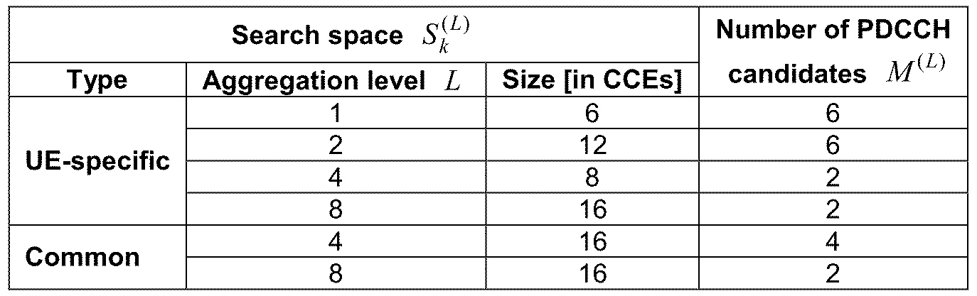
상술한 바와 같이, 단말은 PDCCH를 디코딩하기 위해 단말 특정 서치 스페이스 및 공용 서치 스페이스를 모두 모니터링한다. 여기서, 공용 서치 스페이스(CSS)는 {4, 8}의 집합 레벨을 갖는 PDCCH들을 지원하고, 단말 특정 서치 스페이스(USS)는 {1, 2, 4, 8}의 집합 레벨을 갖는 PDCCH들을 지원한다. 표 5는 단말에 의하여 모니터링되는 PDCCH 후보를 나타낸다. As described above, the UE monitors both the UE-specific search space and the common search space in order to decode the PDCCH. Here, the common search space CSS supports PDCCHs having aggregate levels of {4, 8}, and the UE-specific search space USS supports PDCCHs having aggregate levels of {1, 2, 4, 8} . Table 5 shows the PDCCH candidates monitored by the UE.
수학식 1을 참조하면, 공용 서치 스페이스의 경우 2개의 집합 레벨, L=4 및 L=8에 대해 Yk는 0으로 설정된다. 반면, 집합 레벨 L에 대해 단말 특정 서치 스페이스의 경우 Yk는 수학식 2와 같이 정의된다. Referring to Equation (1), Y k is set to 0 for two aggregate levels, L = 4 and L = 8 for the common search space. On the other hand, in the case of the UE-specific search space for the set level L, Y k is defined as shown in Equation (2).
![]()
![]()
여기서, ![]()
![]()
2. 밀리미터 웨이브(mmWave)2. Millimeter wave (mmWave)
2.1 LoS (Line of Sight)와 NLoS (Non Line of Sight) 전력폭 차2.1 Line-of-sight (LoS) and Non-Line of Sight (NLoS)
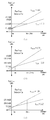
도 6은 거리에 따른 경로 감쇄의 선형 모델링 결과를 나타내는 도면이다.6 is a diagram showing a result of linear modeling of path attenuation according to distance.
도 6(a) 내지 도 6(c)는 각각 서로 다른 지역에서 측정된 선형 모델링 결과로, 28GHz 대역에서 서로 다른 전파 감쇄 상수 값이 도출되는 것을 나타낸다.Figs. 6 (a) to 6 (c) show that different propagation attenuation constants are derived in the 28 GHz band as a result of linear modeling measured in different regions.
도 6(a)는 송신기와 수신기의 거리가 100m인 상황에서 LoS와 NLoS 채널 상황에서의 경로 감쇄가 반사 손실, 회전 손실, 침투 손실 등을 고려하여 각 104.8dB, 150dB로 설정되었고, 28GHz에서의 1m 기준 경로 감쇄 오프셋 61.4dB를 고려하여 선형 필터링 기법을 적용시 LoS와 NLoS의 전파 감쇄 상수는 2.17 및 4.43으로 산출된 것을 가정한다.6 (a), the path attenuation in the case of LoS and NLoS channel is set to 104.8 dB and 150 dB in consideration of return loss, rotation loss, penetration loss, and the like at a distance of 100 m between the transmitter and the receiver, It is assumed that the propagation attenuation constants of LoS and NLoS are calculated to be 2.17 and 4.43 when the linear filtering technique is applied considering the 1 m reference path attenuation offset of 61.4 dB.
도 6(b) 및 도 6(c)는 5m 기준 경로 감쇄 오프셋이 고려된 도면으로, 나머지 고려 요소들은 도 6(a)와 동일하다. 예를 들어, 도 6(c)는 건물과 건물 사이는 약 30m 정도 이며, 3~4개의 캠퍼스 건물로 이루어져 있는데 이러한 건물 밀집도는 경로 감쇄 환경 측면에서 교외 지역 급으로 분류될 수 있다. 반면 도 6(a)의 경로 감쇄 모델은 맨하탄 스트리트 격자 모델에 대하여 Ray tracing 기법으로 시뮬레이션 한 결과에 기반하는 것으로 도 6(b)의 경로 감쇄 모델과 100m 이내의 경로 감쇄 값을 산출함에 있어 보다 유사한 경향을 나타내게 된다. 6 (b) and 6 (c) are diagrams in which a 5 m reference path attenuation offset is considered, and the remaining considerations are the same as in FIG. 6 (a). For example, Fig. 6 (c) is about 30 m between building and building, and consists of 3 ~ 4 campus buildings. Such building density can be classified as suburban area in terms of path attenuation environment. On the other hand, the path attenuation model of FIG. 6 (a) is based on the simulation result of the Raytracing method for the Manhattan street lattice model, and is similar to the path attenuation model of FIG. 6 (b) .
즉, 도 6(a)와 도 6(b)의 NLoS전파 감쇄 상수가 4.43 과 5.76으로 차이가 나지만 참조 거리 감쇄를 도 6(a)는 1m, 도 6(b)는 5m로 설정하는 것을 감안 할 때 100m이내에서의 경로 손실 산출 결과는 도 6(c) 대비 유사한 경향을 발생한다.That is, although the NLoS propagation attenuation constants in Figs. 6A and 6B are different from 4.43 and 5.76, the reference distance attenuation is set to 1 m in Fig. 6A and 5 m in Fig. 6B, The result of path loss calculation within 100 m is similar to Fig. 6 (c).
이러한 경향에 기반하여 본 발명의 실시예들에서 경로 감쇄 모델을 28GHz mmWave 전송에 대한 도심 옥외(urban outdoor) 환경의 LoS/NLoS 경로 감쇄 모델로 적용하는 것을 가정한다. 이러한 모델링 결과에 기반하여 28GHz mmWave 전송에 대한 NLoS채널 환경에서 LoS 채널 환경 대비 경로 감쇄는 100m기준으로 45.2dB의 손실 차가 발생한다.Based on this tendency, it is assumed in the embodiments of the present invention that the path attenuation model is applied to the LoS / NLoS path attenuation model in an urban outdoor environment for 28 GHz mmWave transmission. Based on the modeling results, the path loss compared to LoS channel environment in the NLoS channel environment for 28GHz mmWave transmission is 45.2dB loss difference based on 100m standard.
상술한 경로 감쇄 모델링의 결과를 통해 도출된 전파 감쇄 상수(n) 파라미터의 값을 적용하여 임의의 거리에서의 경로 감쇄 값은 다음 수학식 3과 같이 도출될 수 있다.The path attenuation value at an arbitrary distance can be derived by the following Equation (3) by applying the value of the propagation attenuation constant (n) parameter derived from the result of the path attenuation modeling described above.

수학식 3에서 PL()은 경로 감쇄 함수를 의미하고, d는 송신기와 수신기 간 거리를 의미하며, d0는 기준 거리를 의미한다.In Equation (3), PL () denotes a path attenuation function, d denotes a distance between a transmitter and a receiver, and d 0 denotes a reference distance.
2.2 LoS (Line of Sight)와 NLoS (Non Line of Sight)의 특성2.2 Characteristics of LoS (Line of Sight) and NLoS (Non Line of Sight)
mmWave 신호는 쉐도잉(shadowing)에 매우 민감하다. 예를 들어, mmWave 신호는 벽 등의 장애물로 인해 40dB 내지 80dB의 신호 감쇄가 발생하고, 사람의 몸 그 자체에 의해서도 20 내지 35 dB의 신호 감쇄 쉽게 발생할 수 있다. 또한, 사람의 몸 및 많은 외부의 물질들은 매우 mmWave 신호의 전달에 대해서 매우 심각한 전파 지연을 발생시킬 수 있다. The mmWave signal is very sensitive to shadowing. For example, the mmWave signal can cause signal attenuation of 40 dB to 80 dB due to an obstacle such as a wall, and can easily cause a signal attenuation of 20 to 35 dB by the human body itself. In addition, the human body and many external materials can generate very severe propagation delays for the transmission of very mmWave signals.
도 7은 실내에서 mmWave 신호가 전송되는 상황을 설명하기 위한 도면이고, 도 8은 사람에 의해 mmWave 신호의 감쇄가 발생하는 경우를 나타내는 도면이다.FIG. 7 is a view for explaining a situation where an mmWave signal is transmitted in a room, and FIG. 8 is a diagram showing a case where an mmWave signal is attenuated by a person.
일반적으로 사람이 달릴 때 14.4km/h 정도, 걸을 때는 4.8 km/h 정도 속도로 이동하며, 단거리 달리기 선수가 달릴 때 평균 약 10m/s 정도로 이동하는 것을 가정한다. 이러한 정보를 기반으로 도 7에서 도시한 실내 환경에서 mmWave 신호의 전파 감쇄를 측정하여 도 8과 같은 결과를 얻을 수 있다. mmWave 신호의 전파 감쇄를 측정하기 위한 측정 파라미터는 다음과 같다.Generally, it is assumed that a person moves at a speed of about 14.4 km / h when walking, 4.8 km / h when walking, and an average of about 10 m / s when a short-distance runner runs. Based on this information, the propagation attenuation of the mmWave signal is measured in the indoor environment shown in FIG. 7, and the results shown in FIG. 8 can be obtained. The measurement parameters for measuring the propagation attenuation of the mmWave signal are as follows.
(1) Agilent E8361A vector network analyzer(1) Agilent E8361A vector network analyzer
(2) Vertical polarized circular horn antennas : 20dBi(2) Vertical polarized circular horn antennas: 20dBi
(3) Half beamwidth : 10 degree(3) Half beamwidth: 10 degree
도 8(a)는 장애 물체가 없는 LoS 환경에서 mmWave 신호를 측정한 결과이며, 도 8(b)는 사람의 몸에 의한 전파 감쇄가 발생하는 NLoS 환경에서의 mmWave 신호를 측정한 결과이다. 도 8을 참조하면 LoS/NLoS 환경의 차이가 5m 이내에서 약 15dB 차이가 난다. 28GHz 대역에서는 100m 거리에서 LoS/NLoS 전력 손실 차는 약 43dB가 발생할 수 있다. 8 (a) is a result of measuring the mmWave signal in a LoS environment without an obstacle, and Fig. 8 (b) is a result of measuring the mmWave signal in an NLoS environment in which propagation attenuation by a human body occurs. Referring to FIG. 8, the difference of the LoS / NLoS environment is about 15 dB within 5 m. In the 28 GHz band, the LoS / NLoS power loss difference may be about 43 dB at a distance of 100 m.
도 7 및 도 8에서 0.6 m/s 로 움직이는 사람에 의한 LoS에서 NLoS로의(LoS/NLoS) 전이 시간(transition time)은 약 150ms 정도이다. 따라서, 10m/s로 움직이는 물체의 LoS/NLoS 전이 시간 변화는 (0.6*0.15)/10 = 9ms 정도로 나타낼 수 있다. 만약, 사람 손의 갑작스런 스윙이나, 다른 특수한 상황에서는 이러한 전이 시간 변화는 더 짧아 질 수 있다. 따라서 이러한 LoS/NLoS 환경의 전이 시간 구간은 단말의 움직임과 환경 변화에 의해 발생하기 때문에, LoS/NLoS 변화를 예측하기가 매우 어렵다.The transition time from LoS to NLoS (LoS / NLoS) by a person moving at 0.6 m / s in FIG. 7 and FIG. 8 is about 150 ms. Therefore, the change in LoS / NLoS transition time of an object moving at 10 m / s can be expressed as (0.6 * 0.15) / 10 = 9 ms. This sudden swing of the human hand, or other special circumstances, can result in a shorter transition time. Therefore, it is very difficult to predict the LoS / NLoS change because the transition time interval of the LoS / NLoS environment is caused by the movement of the terminal and the environment change.
도 9는 주파수에 따른 LoS/NLoS 전이 시간의 변화와 수신 전력과의 관계를 나타내는 도면이다. 도 9에서 가로 축은 시간 영역을 세로 축은 주파수 영역을 나타낸다.9 is a graph showing a relationship between a change in LoS / NLoS transition time and a received power according to a frequency. In FIG. 9, the horizontal axis represents the time domain and the vertical axis represents the frequency domain.
도 9를 참조하면, LoS에서 NLoS로의 전이 시간은 주파수가 높은 환경에서는 매우 급격히 변화하고, 주파수가 낮은 환경에서는 그 변화율이 낮아진다. 그러나, 주파수가 낮은 환경에서는 LoS/NLoS간 전력 차가 작아질 수 있다.Referring to FIG. 9, the transition time from LoS to NLoS varies very rapidly in a high frequency environment and decreases in a low frequency environment. However, in a low-frequency environment, the power difference between LoS / NLoS can be reduced.
도 9와 같이 LoS에서 NLoS 또는 NLoS에서 LoS로 변할 때 전력 감쇄나 증가하는 시간은 어떻게 LoS에서 NLoS로 변화하는지에 따라 변경될 수 있다. 고주파 영역에서, LoS/NLoS 천이 시 수신 신호 감쇄 폭은 커지고, 저주파에서는 수신 신호 감쇄 폭이 작거나 거의 나타나지 않는다. 인접한 밴드 사이에서는 어느 시간 t에서 순간 전력 감소 기울기는 거의 비슷하게 발생한다.As shown in FIG. 9, when the NLoS in the LoS or the NLoS or the NLoS changes to the LoS, the power decay or the increase time can be changed depending on how the LoS changes to the NLoS. In the high frequency range, the attenuation width of the received signal becomes large at the time of LoS / NLoS transition, and the attenuation width of the received signal is small or hardly appears at a low frequency. The instantaneous power reduction slope at any time t between adjacent bands occurs almost identically.
상술한 바와 같이, mmWave 시스템은 초고주파 대역에서 동작할 가능성이 매우 크다. 즉, mmWave 신호에 대해 LoS/NLoS 간 천이는 외부 환경에 매우 민감하게 변동할 수 있다.As mentioned above, the mmWave system is very likely to operate in the very high frequency band. That is, the transition between LoS / NLoS for the mmWave signal can be very sensitive to the external environment.
도 10은 mmWave 하향링크 수신 신호 변화로 인해 이전 CQI 피드백을 기반으로 동작시 신호 검출이 실패할 수 있음을 나타내기 위한 도면이다.10 is a diagram for indicating that signal detection may fail during operation based on previous CQI feedback due to a change in the mmWave downlink received signal.
도 10은 8HARQ 절차에 의해서 CQI를 통해 얻어진 채널 정보를 디코딩하고, 그 정보를 통해 DCI 포맷, MCS(modulation and coding scheme) 및 RV(redundancy version) 등의 정보를 결정하는 과정을 나타낸다. 이때의 mmWave 링크에서 LoS 에서 NLoS로 변하는 천이 시간(transition time) 이 발생 했을 때, CQI 정보가 쓸모 없게(outdated) 되는 상황을 확인할 수 있다.FIG. 10 shows a process of decoding channel information obtained through the CQI according to the 8HARQ procedure, and determining information such as a DCI format, a modulation and coding scheme (MCS), and a redundancy version (RV) through the information. At this time, when the transition time from LoS to NLoS occurs in the mmWave link, the CQI information is outdated.
하향링크 전송이 시작되는 시간은 4 TTI (LTE 기준 4ms)정도라고 할 때, 이러한 LoS/NLoS간 천이가 발생하게 되면, 기존 시스템에서 가장 최신에 검출된 CQI 정보는 mmWave 특성 상 LoS가 NLoS 상황으로 변할 때 잘못된 채널 정보를 가지게 될 가능성이 매우 크다. 따라서, 기지국은 잘못된 MCS 및 RV 등 스케줄링 정보를 단말에게 전송하게 되어 신호 검출에 대해 실패 가능성이 많아지고, 시스템 내 처리량(throughput) 성능 열화를 유발할 수 있다.When the LoS / NLoS transition occurs, the latest CQI information detected in the existing system is the NLoS situation due to the mmWave characteristic. There is a great possibility that the channel information will have wrong channel information. Therefore, the BS transmits scheduling information such as erroneous MCS and RV to the UE, which may increase the likelihood of failure in signal detection and cause deterioration of throughput performance in the system.
mmWave 하향링크의 채널 변화를 극복하는 가장 간단한 해결 방법은 단말이 CQI 피드백을 더 자주 보내도록 설정하는 것이다. LTE 시스템의 FDD 기준으로 볼 때 CQI 보고시 가장 작은 주기는 2개 서브프레임 주기이다. 하지만, 기지국에서 수신한 CQI를 디코딩하기 위한 비용 효율(Cost efficient) 측면에서 (빠른 처리 시간(processing time) 요구) 부담이 될 수 있다. 또한, 기지국이 새로운 CQI 피드백을 기지국이 수신하여 디코딩하는데 필요한 시간에 다시 LoS/NLoS간 천이가 발생함으로써, 새로 수신한 CQI 마저도 쓸모 없게 되는 현상이 발생 할 수 있다. 게다가, CQI는 SINR(signal-to-noise-plus-interference ratio) 기반 정보를 피드백하는 지시자로써, 기지국이 수신한 CQI 자체에는 이미 수신 신호에 대한 간섭에 의한 정보도 포함되어 있다.The simplest solution to overcome the channel change of the mmWave downlink is to set the terminal to send CQI feedback more frequently. In the FDD standard of the LTE system, the smallest period in CQI reporting is two subframe periods. However, it may be burdened in terms of cost efficiency (fast processing time) for decoding the CQI received from the base station. In addition, a transition between LoS and NLoS occurs again at a time required for the base station to receive and decode the new CQI feedback by the base station, so that even a newly received CQI may become useless. In addition, the CQI is an indicator for feedback of signal-to-noise-plus-interference ratio (SINR) -based information, and the CQI received by the base station already includes information due to interference with the received signal.
따라서, 단말 및/또는 기지국에서 LoS/NLoS 천이를 구별하기 위해서는 해당 시점에서 수신 전력 기반의 측정으로 판단하는 것이 바람직하다. 수신 전력 기반의 채널 정보를 보내기 위한 방법으로, 단말이 하향링크 참조신호의 RSRP를 측정하여 보고하는 피드백 방법이 있다. 다만, RSRP는 일반적으로 긴 시간 구간(long term)에 대한 채널 측정에 바람직하다. 왜냐하면, 단말이 RSRP를 측정하는데 걸리는 최대 허용 시간은 200ms로 mmWave 시스템 관점에서는 너무 긴 시간이다. 즉, LoS/NLoS 천이는 짧은 시간 구간(short term)에서의 채널 측정 관점에서 판단해야 하기 때문에, 기존의 채널 상황을 보고하는 방법으로는 mmWave 시스템의 LoS/NLoS 천이를 검출하고 이에 따른 MCS 등을 조절하기 어렵다.Therefore, in order to distinguish the LoS / NLoS transition from the terminal and / or the base station, it is preferable to determine the measurement based on the received power at the corresponding point in time. There is a feedback method in which the UE measures and reports the RSRP of the downlink reference signal. However, RSRP is generally preferred for channel measurements over long time periods. Because the maximum allowed time for a terminal to measure RSRP is 200ms, it is too long in terms of the mmWave system. In other words, since LoS / NLoS transitions should be judged from the viewpoint of channel measurement in a short term, a method of reporting the existing channel conditions is to detect the LoS / NLoS transitions of the mmWave system, It is difficult to control.
2.3 mmWave LoS와 NLoS 천이와 수신 전력 시나리오2.3 mmWave LoS and NLoS Transition and Receive Power Scenario
도 11은 mmWave LoS/NLoS 천이가 링크 환경에 영향을 미치는 모습을 설명하기 위한 수신 전력 시나리오들을 나타내는 도면이다.11 is a diagram showing received power scenarios for explaining how the mmWave LoS / NLoS transition affects the link environment.
도 11의 세로축은 수신 전력 세기를 의미하고, 가로축은 시간 단위를 의미한다. 수신 전력의 최소값(즉, 수신기 감도 레벨(RSL: Receiver Sensitivity Level))은 수신단이 데이터를 수신할 수 있는 최소 수신 전력 값을 의미한다. 즉, 수신단은 NLoS 상황으로 변경되더라도 RSL 이상의 데이터에 대해서는 정상적으로 수신할 수 있다.The vertical axis in FIG. 11 indicates the received power intensity, and the horizontal axis indicates the time unit. The minimum value of the received power (i.e., the receiver sensitivity level (RSL)) means a minimum received power value at which the receiving end can receive data. That is, even if the receiving end is changed to the NLoS status, it can normally receive data of RSL or more.
이러한 가정을 기반으로 도 11(a)를 참조하면, NLoS 상태의 수신 전력은 RSL보다 낮으며 NLoS 지속 시간이 길다. 도 11(b)의 경우, NLoS 상태의 수신 전력은 RSL보다 높으며 NLoS 지속 시간이 길다. 도 11(c)의 경우, NLoS 상태의 수신 전력은 RSL보다 낮으며 NLoS 지속 시간이 짧다. 도 11(d)의 경우, NLoS 상태의 수신 전력은 RSL보다 높으며 NLoS 지속 시간이 짧음을 확인할 수 있다.Based on this assumption, referring to FIG. 11 (a), the received power in the NLoS state is lower than the RSL and the NLoS duration is long. 11 (b), the received power in the NLoS state is higher than the RSL and the NLoS duration is long. 11 (c), the received power in the NLoS state is lower than the RSL and the NLoS duration is short. 11 (d), it is confirmed that the received power in the NLoS state is higher than the RSL and the NLoS duration is short.
수신단이 폴백(Fallback)을 효과적으로 수행 하기 위해서는 도 11에 도시된 시나리오 별로 mmWave 폴백 방법을 다르게 고려하는 것이 바람직하다. 예를 들어 도 11(a)같은 수신 전력 시나리오에서는 RSL 아래로 수신 전력이 내려가고 NLoS 상태로 지속되는 환경이다. 따라서, 수신단은 링크가 단절(failure)되면 무선 링크 단절 과정(Radio link failure procedure)을 빨리 수행해야 한다. 이때, 도 12와 같이 기존 무선 링크 실패 과정과 같이 두 번의 링크 복원(link recovery) 단계를 거 친 후에도 수신단의 링크가 단절되면, 수신단은 유휴 단계로 진입한다. 이때, 이 두 차례의 페이즈를 통한 링크 복원 단계들은 최소 1000ms의 시간이 소요 되기 때문에, 링크가 계속 단절 상태 되면 수신 전송량이 급격하게 줄게 된다. 따라서, 도 11(a) 경우 수신단은 링크가 단절 되기 전에 빨리 폴백을 수행하는 것이 바람직하다.In order for the receiver to effectively perform fallback, it is desirable to consider the mmWave fallback method differently for each scenario shown in Fig. For example, in the receive power scenario as shown in FIG. 11 (a), the receive power decreases below the RSL and the NLoS state continues. Therefore, the receiving end must perform a radio link failure procedure quickly if the link fails. At this time, as shown in FIG. 12, if the link of the receiving end is disconnected even after performing two link recovery steps as in the existing radio link failure process, the receiving end enters the idle step. In this case, since the link restoration steps through these two phases take a minimum of 1000 ms, if the link is continuously disconnected, the amount of received transmission is drastically reduced. Therefore, in the case of Fig. 11 (a), it is preferable that the receiving end perform fallback immediately before the link is disconnected.
도 12는 무선 링크 단절 과정의 일례를 나타내는 도면이다. 도 12를 참조하면, 수신단은 일반 동작(normal operation)을 수행하다가, 무선 링크에 문제가 발생하였음을 감지할 수 있다. 이때, 수신단은 첫 번째 페이즈(phase)로 링크 복원 과정을 수행하는데, 이때 복원 타이머(T310)이 동작하며 0~2000ms가 소요될 수 있다. 만약, T310 타이머 동안 링크가 복원되지 않으면, 수신단은 두 번째 페이즈에 진입하여 복원 타이머(T311)을 동작시킨다. 해당 타이머는 1000ms까지 설정될 수 있다. 수신단은 T310, T311 타이머 구간 내에서 링크가 복원되면 송신단과 다시 통신을 수행하지만, 두 번째 페이즈까지 링크가 복원되지 않으면 유휴 상태로 진입한다. 도 12에 대한 더욱 자세한 설명은 3GPP TS 36.300 규격 문서를 참조한다. 12 is a diagram showing an example of a radio link disconnection process. Referring to FIG. 12, the receiving end performs a normal operation, and can detect that a problem has occurred in the wireless link. At this time, the receiver performs a link restoration process in the first phase. At this time, the restoration timer (T310) operates and may take 0 to 2000 ms. If the link is not restored during the T310 timer, the receiving end enters the second phase and operates the restoration timer T311. The timer can be set up to 1000 ms. When the link is restored within the T310 and T311 timer periods, the receiver communicates with the transmitter again, but enters the idle state if the link is not restored until the second phase. For a more detailed description of Figure 12, refer to the 3GPP TS 36.300 specification document.
다시 도 11을 참조하면, 도 11(b) 및 (d)는 수신단이 기존 폴백 절차(본 발명의 실시예들에서, 폴백 절차는 핸드오버와 유사한 과정임을 가정한다)를 수행하더라도, 송신단과 링크가 계속 연결 되어 있기 때문에 아무런 문제가 발생하지 않는다. 11 (b) and 11 (d), although the receiving end performs the existing fallback procedure (assuming that the fallback procedure is similar to the handover in the embodiments of the present invention) There is no problem because it is connected continuously.
그러나, 도 11 (c)에 도시된 시나리오의 경우, 수신단이 폴백을 트리거하여 완료하기 까지의 시간이 LoS/NLoS 천이가 측정된 시점부터 다시 LoS로 회귀하는 시간 보다 짧으면, 폴백을 수행하는 것이 시나리오 상 유리하다. 그러나, 그 반대 상황(NLoS 구간이 짧은 경우)에서는 폴백을 수행하지 않는 것이 수신단의 데이터 처리량 관점에서 유리하다. 따라서 수신단이 이러한 폴백 수행 조건들을 각 시나리오마다 잘 수행하기 위해서 수신단은 각 수신 전력 시나리오들을 미리 추정 및 예측하는 것이 바람직하다.However, in the scenario shown in Fig. 11 (c), if the time until the receiving end triggers and completes the fallback is shorter than the time that the LoS / NLoS transition returns from the measured time to the LoS, It is advantageous. However, in the opposite situation (when the NLoS interval is short), it is advantageous from the viewpoint of the data throughput of the receiving end not to perform fallback. Therefore, it is preferable that the receiving end estimates and predicts the respective reception power scenarios in advance in order for the receiving end to perform the fallback performing conditions for each scenario well.
2.4 mmWave LoS와 NLoS 천이에 따른 수신 전력 추정 시나리오2.4 Receive power estimation scenario based on mmWave LoS and NLoS transition
수신단(예를 들어, 단말)이 LoS에서 NLoS 상황으로 바뀔 때 도 11(a)와 도 11(b) 상황을 구분하기 위해서는 링크 단절이 발생하는 시점을 미리 예측 및 추정하는 것이 중요하다.It is important to predict and estimate the time at which the link disconnection occurs in advance in order to distinguish the situation between Fig. 11 (a) and Fig. 11 (b) when the receiving terminal (for example, terminal) changes from LoS to NLoS.
도 13은 단말이 LoS 환경에서 NLoS 환경으로 천이하는 상황, 즉 NLoS가 발생한 경우를 추정하는 방법을 설명하기 위한 도면이다.13 is a diagram for explaining a method of estimating a situation in which a UE transits from a LoS environment to an NLoS environment, that is, when a NLoS occurs.
도 13(a)와 같이 링크 단절이 발생하는 순간, 단말은 LoS에서 NLoS로의 천이를 추정할 수 있다. 도 13(a)와 같이 단말은 LoS/NLoS 천이 시에 mmWave LoS/NLoS 기울기 정보를 추정(출원 번호 PCT/KR2015/006716 사건 참조)하고, 단말과 mmWave BS 간의 거리를 LoS 상황에서 파일럿을 이용하여 측정하여 전송 주파수 정보를 통해 LoS와 NLoS 상황의 수신 세기 폭을 추정하는 단계를 수행함으로써, 링크 단절이 발생하는 시점을 추정할 수 있다.As shown in FIG. 13 (a), the UE can estimate a transition from LoS to NLoS at the moment when link disconnection occurs. As shown in FIG. 13 (a), the UE estimates the mmWave LoS / NLoS slope information in the LoS / NLoS transition (see PCT / KR2015 / 006716 case) and calculates the distance between the terminal and the mmWave BS using the pilot And estimating the reception intensity width of the LoS and the NLoS situation through the transmission frequency information, thereby estimating the time at which the link disconnection occurs.
또한, 단말은 도 11(c) 시나리오에 대해서 도 13(b)와 같이 NLoS 상황에서 LoS로 회귀하는 현상도 예측 및 추정하는 것이 바람직하다. 왜냐하면, 폴백 트리거링을 수행할지 여부는 NLoS 전력이 RSL보다 낮을 때, 해당 수준이 얼마나 지속 되는지에 따라 결정 되기 때문이다.It is also preferable that the terminal predicts and estimates the phenomenon of returning to LoS in the NLoS situation as shown in Fig. 13 (b) for the scenario of Fig. 11 (c). This is because whether or not to perform fallback triggering is determined by how long the level is when the NLoS power is lower than the RSL.
도 13(b)와 같이 LoS -> NLoS -> LoS로 천이하는 동작에 대한 시간 길이는 mmWave 단말의 고유 움직임 패턴에 민감하게 작용된다. 따라서, 단말은 확률적, 경험적으로 단말의 움직임 패턴 정보를 통해 NLoS 천이 여부를 추정할 수 밖에 없다. 따라서 단말은 확률적인 추정으로 인해 NLoS 추정에 오류가 발생할 수 있다.As shown in FIG. 13 (b), the time length for the transition from LoS to NLoS to LoS is sensitive to the unique motion pattern of the mmWave terminal. Therefore, the UE must estimate the NLoS transition probability through probabilistic and empirical movement pattern information of the UE. Therefore, an error may occur in the NLoS estimation due to the probabilistic estimation of the UE.
따라서, 이하에서 설명하는 본 발명의 실시예들에서는 NLoS에서 LoS로 회귀하는 시나리오는 고려 하지 않고, 수신 전력 시나리오 중에 링크 단절이 발생하는 시나리오와 링크 단절이 발생하지 않는 시나리오에 대한 폴백 방법들을 제안한다.Therefore, in the embodiments of the present invention described below, there is proposed a fallback method for a scenario in which a link disconnection occurs and a scenario in which a link disconnection does not occur during a received power scenario without considering a scenario in which the NLoS returns to the LoS .
2.5 레가시 폴백 과정2.5 Legacy Fallback Course
도 14는 레가시 핸드오버 과정을 설명하기 위한 도면이다. 14 is a diagram for explaining a legacy handover process.
도 11(a)에서 설명한 바와 같이 수신단이 LoS/NLoS 천이를 측정한 이후 링크 단절 이전에 빠르게 폴백을 수행하는 것이 전송 속도 손실을 막는데 가장 중요하다. 도 11(a) 상황에서 기존 폴백 방법은 핸드오버 과정과 동일하다. 따라서, 기존 핸드오버 과정이 시작하여 완료될 때까지의 시간 딜레이를 구해 LoS/NLoS 천이 시간과 비교함으로써, 수신단이 NLoS 천이 측정 이후 링크 단절이 발생하기 전까지 기존 폴백 방법이 수행 가능한 것인지 확인할 수 있다.As described with reference to FIG. 11 (a), it is most important to quickly perform a fallback before the link disconnection after the receiver measures the LoS / NLoS transition, in order to prevent the transmission speed loss. 11 (a), the existing fallback method is the same as the handover procedure. Accordingly, it is possible to determine whether the existing fallback method can be performed until the link disconnection occurs after the NLoS transition measurement by the receiver by comparing the time delay from the start of the existing handover process to the completion of the handover and comparing the time delay with the LoS / NLoS transition time.
도 14는 기존의 레가시 핸드오버 지연 속도(handover latency)를 일반적으로 계산한 것이다. 각 단계 마다 소요 시간은 다음과 같다.FIG. 14 generally illustrates the existing legacy handover latency. The time required for each step is as follows.
(1) 핸드오버 준비(Handover Preparation) 단계는 대략 17.8 ms 정도 소요되고, (2) 핸드오버 실행 단계는 대략 10.5 ms 정도 소요되며, (3) 핸드오버 완료(Handover Completion) 단계는 대략 120 ms 정도 소요된다. 따라서, 총 핸드오버 지연 시간은 대략 148.3 ms로 추정될 수 있다.(1) the handover preparation step takes about 17.8 ms, (2) the handover execution step takes about 10.5 ms, and (3) the handover completion step takes about 120 ms . Therefore, the total handover delay time can be estimated to be approximately 148.3 ms.
핸드오버 준비 단계가 넘어가면 수신단은 링크 회복 과정을 수행한다. 따라서, 핸드오버 준비 과정과 LoS/NLoS 천이 과정을 비교하면, 수신단(즉, 단말)이 링크 단절이 발생하기 이전에 기존 폴백 과정(즉, 핸드오버)으로 LoS/NLoS 천이를 처리할 수 있는지 여부를 알 수 있다. If the handover preparatory step is exceeded, the receiving end performs the link recovery process. Therefore, comparing the handover preparation procedure and the LoS / NLoS transition process, it is possible to determine whether the receiving end (i.e., the terminal) can process the LoS / NLoS transition by the existing fallback process (i.e., handover) .
핸드오버 준비 단계는 대략 17.8 ms 이므로, 단말의 움직임 패턴이 전력 달리기 수준일 때를 유저가 일반적은 상황에서 빠르게 움직일 수 있는 정도라고 보면, mmWave 단말을 위해 핸드오버 준비 단계는 약 10ms 정도로 줄어드는 것이 바람직하다. Since the handover preparation stage is approximately 17.8 ms, it is preferable that the handover preparation step for the mmWave terminal should be reduced to about 10 ms when the user can move quickly in a general situation when the mobile movement pattern of the terminal is at the power running level Do.
따라서, 이하에서 설명하는 본 발명의 실시예들은 mmWave 수신 전력 시나리오를 도시한 도 11(a) 및 도 11(b)를 위하여, 기존 폴백 절차를 10ms 정도 줄이는 것을 목표로 한다.Thus, the embodiments of the present invention described below aim at reducing the existing fallback procedure by about 10 ms for Figs. 11 (a) and 11 (b) illustrating the mmWave receive power scenario.
3. mmWave 폴백 방법3. mmWave Fallback Method
이하에서는 mmWave 시스템의 LoS/NLoS 천이 상황이 발생시에 링크 단절이 발생하기 전에 수신단에서 빠르게 레가시 기지국으로 폴백을 수행하기 위한 요구 사항을 전송하고, 이에 수반되는 정보들을 미리 제공하는 방법들을 제안한다. 이를 통해 폴백 수행 시간을 줄이는 방법들을 아울러 제안한다. 또한, 이하에서 설명의 편의를 위해 수신단은 mmWave 단말이고, 송신단은 mmWave 기지국인 것을 가정한다.In the following, we propose a method to transmit the requirement to perform fallback from the receiving end to the legacy base station before the occurrence of the link disconnection when the LoS / NLoS transitions of the mmWave system occur, and to provide the accompanying information in advance. We also propose methods for reducing fallback execution time. For convenience of description, it is assumed that the receiving end is a mmWave terminal and the transmitting end is a mmWave base station.
3.1 링크 단절을 피하기 위한 폴백 조건3.1 Fallback conditions to avoid link disconnection
링크 단절을 피하기 위한 첫 번째 폴백 조건으로, mmWave 기지국과 레가시 기지국이 중첩 배치된 네트워크 환경에서 mmWave 기지국과 레가시 기지국은 mmWave 단말과 항상 RRC 연결 상태를 유지하도록 구성될 수 있다.As a first fallback condition to avoid link disconnection, the mmWave base station and the legacy base station can be configured to always maintain the RRC connection state with the mmWave terminal in a network environment in which the mmWave base station and the legacy base station are overlapped.
도 15는 mmWave 단말에 대해 빠른 폴백을 위한 초기 접속 상태를 설명하기 위한 도면이다.15 is a diagram for explaining an initial connection state for quick fallback to the mmWave terminal.
본 발명의 실시예들에서 레가시 기지국은 LTE/LTE-A 시스템에서 지원하는 셀룰러 기지국을 의미하며, mmWave 기지국은 초고주파 대역의 mmWave 동작을 지원하는 기지국을 의미한다. 다만, 셀룰러 기지국에서 초고주파 대역의 mmWave 동작을 지원하는 경우에는 mmWave 기지국으로 동작할 수 있다. In the embodiments of the present invention, the legacy base station means a cellular base station supported in the LTE / LTE-A system, and the mmWave base station means a base station supporting the mmWave operation in a very high frequency band. However, if the cellular base station supports the mmWave operation of a very high frequency band, it can operate as an mmWave base station.
도 15를 참조하면, 레가시 기지국은 S-GW(Serving GateWay) 및 MME(Mobility Management Entity)와 X2 인터페이스로 연결되어 있고, 레가시 기지국과 mmWave 기지국은 Xn 인터페이스로 연결되어 있는 것을 가정한다. 또한, 레가시 기지국과 S-GW, 레가시 기지국과 mmWave BS는 서로 이상적인 백홀로 연결되어 있는 것을 가정한다. 또한, mmWave 기지국과 단말은 mmWave 링크로 연결되어 있을 수 있다.Referring to FIG. 15, it is assumed that a legacy base station is connected to an S-GW (Serving GateWay) and an MME (Mobility Management Entity) through an X2 interface, and a legacy base station and an mmWave base station are connected by an Xn interface. It is also assumed that the legacy base station, the S-GW, the legacy base station and the mmWave BS are connected to each other with an ideal backhaul. In addition, the mmWave base station and the terminal may be connected by an mmWave link.
도 15와 같은 가정하에, mmWave 기지국, 레가시 기지국과 타겟 단말이 각각 RRC 연결 상태이면, 핸드오버 인터럽트 시간은 생략 가능하며, 전체 폴백에 소요되는 시간은 도 14에 도시된 핸드오보 과정을 기준으로 137.8ms로 줄어들 수 있다. 15, when the mmWave base station, the legacy base station, and the target terminal are respectively in the RRC connection state, the handover interrupt time can be omitted, and the time required for the entire fallback is 137.8 based on the handover process shown in FIG. ms. < / RTI >
링크 단절을 피하기 위한 두 번째 폴백 조건으로, mmWave 헷넷(hatnet) 접속시 네트워크 연결 상태는 S-GW -> 레가시 BS -> mmWave BS를 기본으로 한다. As a second fallback condition to avoid link disconnection, the network connection status when connecting mmWave Httnet (Hatnet) is based on S-GW -> Legacy BS -> mmWave BS.
예를 들어, 도 15와 같이 mmWave 단말이 네트워크에 초기 접속을 수행하는 경우에 S-GW에서 레가시 기지국, 레가시 기지국에서 mmWave 기지국으로, mmWave 기지국에서 mmWave 단말 순서로 설정이 완료될 수 있다. 이러한 경우, mmWave 단말이 mmWave 링크 상에서 LoS/NLoS 천이를 검출하여 폴백을 수행하는 경우에도 S-GW와 레가시 기지국간 링크는 변하지 않는다. 따라서 도 14에 도시된 핸드오버 완료 과정은 고려하지 않아도 된다. 이로 인해, 레가시 핸드오버 과정과 비교하여 120ms 정도가 줄어들 수 있다.For example, as shown in FIG. 15, when the MMWave terminal performs an initial connection to the network, the setup of the legacy base station in the S-GW, the mmWave base station in the legacy base station, and the mmWave terminal in the mmWave base station can be completed. In this case, the link between the S-GW and the legacy base station does not change even when the mmWave UE detects a LoS / NLoS transition on the mmWave link and performs fallback. Therefore, the handover completion process shown in FIG. 14 may not be considered. As a result, it can be reduced by about 120 ms compared with the legacy handover process.
따라서, 첫 번째 및 두 번째 조건이 달성되는 경우, 도 14에서 도시한 폴백 과정에 대한 지연은 148.3ms에서 17.8ms로 줄어들 수 있다. Thus, if the first and second conditions are achieved, the delay for the fallback process shown in FIG. 14 can be reduced from 148.3ms to 17.8ms.
링크 단절을 피하기 위한 세 번째 폴백 조건은 mmWave 단말이 폴백 트리거링을 수행하는 주체로 설정되는 것이다.The third fallback condition to avoid link disconnection is that the mmWave terminal is set as the subject performing fallback triggering.
도 16은 레가시 시스템에서 수행되는 4단계의 폴백 준비단계가 1 단계의 폴백 준비단계로 수행되는 방법을 설명하기 위한 도면이다.16 is a diagram for explaining a method in which a fallback preparation step of four stages performed in a legacy system is performed in a fallback preparation stage of a first stage.
도 16(a)는 레가시 기지국에서 폴백으로 수행되는 핸드오버 과정을 나타낸다. 이때, 도 16(a)에서 핸드오버 단계는 4단계의 과정을 거쳐 수행되며, 대략 4ms의 시간이 소요된다. 왜냐하면, 기지국에서 핸드오버를 제어하는 경우, 단말의 채널 측정 결과를 기지국에 전달하고, 이에 대해서 핸드오버 수행 여부를 단말에 알려줘야하기 때문이다. 그러나, 도 16(b)는 mmWave 단말이 mmWave 폴백을 결정하는 경우, mmWave 단말은 레가시 기지국으로 통해 폴백 요청을 전송하면 충분하다. 16 (a) shows a handover process performed in fallback at a legacy base station. In this case, the handover step in FIG. 16 (a) is performed through a four-step process, and takes approximately 4 ms. This is because, when the base station controls the handover, it transmits the channel measurement result of the terminal to the base station and informs the terminal whether the handover is performed. 16 (b), however, when the mmWave terminal determines the mmWave fallback, it is sufficient if the mmWave terminal transmits a fallback request to the legacy base station.
따라서, 세 번째 조건으로 인해, 최종 적으로 전체 폴백 지연은 전파 지연(Propagation Delay) 1ms, 처리 지연(Processing Delay) 3ms 및 S1 베어러 설립(S1 Bearer Establishment) 7.5m만이 고려되어 총 11.5ms로 줄어들게 된다. 그러므로, mmWave 단말은 대략 10ms 내외의 mmWave 폴백 과정을 수행할 수 있다.Therefore, due to the third condition, finally the total fallback delay is reduced to 11.5ms in total, taking into consideration only Propagation Delay 1ms, Processing Delay 3ms and S1 Bearer Establishment 7.5m . Therefore, the mmWave terminal can perform the mmWave fallback process in about 10ms.
3.2 링크 단절을 피하기 위한 빠른 폴백 수행 방법3.2 How to perform quick fallback to avoid link disconnection
3.2.1 빠른 폴백 준비단계3.2.1 Steps to prepare for quick fallback
이하에서는 빠른 폴백을 준비하는 방법에 대해서 설명한다. Hereinafter, a method of preparing for rapid fallback will be described.
도 17은 링크 단절을 피하기 위한 빠른 폴백을 수행하는 방법을 설명하기 위한 도면이다. 17 is a diagram for explaining a method of performing quick fallback to avoid link disconnection.
도 17(a)는 빠른 폴백 트리거를 위한 전제 조건을 설명하기 위한 도면이다. 빠른 폴백 트리거를 위한 전제 조건으로 레가시 기지국, mmWave 기지국 및 mmWave 단말 간에 RRC 연결이 설정되어 있는 것을 가정한다. 또한, mmWave 단말과 MME 간 NAS(Non-Access Stratum) 시그널링을 위한 EMM 등록이 되어 있고, ECM(Evolved Packet system connection Management) 연결이 설정된 것을 가정한다. 또한, X2 인터페이스는 mmWave 링크 전송 속도를 지원할 수 있는 이상적 백홀로 연결되어 있는 것을 가정한다. 이하에서는 EMM 등록 및 ECM 연결에 대해서 설명한다.17 (a) is a diagram for explaining a precondition for a quick fallback trigger. It is assumed that the RRC connection is established between the legacy base station, the mmWave base station and the mmWave terminal as preconditions for fast fallback triggering. It is also assumed that an EMM is registered for non-access stratum (NAS) signaling between the mmWave terminal and the MME, and an ECM (Evolved Packet system connection) connection is established. It is also assumed that the X2 interface is connected to an ideal backhaul capable of supporting the mmWave link transmission speed. EMM registration and ECM connection are described below.
도 18은 NAS 시그널링과 RRC 연결을 설명하기 위한 계층 구성도의 일례이다. 18 is an example of a hierarchical diagram for explaining NAS signaling and RRC connection.
도 18을 참조하면, 단말과 기지국은 RRC 연결이 설정되어 있고, 기지국과 MME 간에는 S1AP를 통해 S1 시그널링 연결이 설정된 것을 확인할 수 있다. 또한, 단말과 MME 간에 시그널링을 위해 NAS 시그널링 연결(즉, ECM 연결)이 설정된 것을 가정한다. Referring to FIG. 18, an RRC connection is established between a terminal and a base station, and an S1 signaling connection is established between the base station and the MME through an S1AP. It is also assumed that an NAS signaling connection (i.e., an ECM connection) is established for signaling between the UE and the MME.
NAS 계층은 베어러 컨텍스트 활성화/비활성화를 수행하는 ESM 상태, EEM 등록/해제를 수행하는 EMM 상태 및 ECM 연결/유휴를 담당하는 ESM 상태로 구성된다. 다음 표 6은 도 17의 연결 상태를 설명하기 위한 것이다. The NAS layer is composed of an ESM state for performing bearer context activation / deactivation, an EMM state for performing EEM registration / release, and an ESM state for managing ECM connection / idle. Table 6 below is for explaining the connection state of Fig.
다시 도 17을 참조하여 설명한다.Referring back to FIG.
도 17(a)를 통해 설명한 가정들 및 3.1절에서 설명한 세 가지 조건들에 더하여, 링크 단절을 피하기 위한 네 번째 폴백 조건으로 레가시 기지국은 레가시 하향링크 대역으로 mmWave 단말을 위해 할당할 자원과 관련된 자원 관련 정보를 mmWave 단말에 미리 전송할 수 있다.In addition to the assumptions described in FIG. 17 (a) and the three conditions described in Section 3.1, as a fourth fallback condition for avoiding link disconnection, the legacy base station transmits resources related to resources to be allocated for the mmWave terminal in the legacy downlink band Related information to the mmWave terminal in advance.
이때, 자원 관련 정보는 단말이 폴백 요청 메시지를 레가시 기지국으로 전송하기 전에 레가시 기지국이 주기적으로 레가시 하향링크를 통해 mmWave 단말에게 전송하는 메시지를 의미한다.At this time, the resource related information means a message transmitted from the legacy base station to the mmWave terminal periodically via the legacy downlink before the terminal transmits the fallback request message to the legacy base station.
자원 관련 정보에는 mmWave 임시 셀 식별자(mmWave Temporary BS Cell ID) 및 레가시 기지국의 하향링크 전송 전력 세기 정보가 포함될 수 있다.The resource related information may include the mmWave Temporary BS Cell ID and the downlink transmission power intensity information of the legacy base station.
mmWave 임시 셀 식별자는 보안을 고려하여 사용되는 임시적인 mmWave 셀 식별자를 의미한다. mmWave 임시 셀 식별자를 기반으로 mmWave 단말은 현재 연결된 mmWave 기지국이 무엇인지 알 수 있고, mmWave 링크 단절 이후에도 다시 LoS 링크로 복귀할 때 복귀할 대상 mmWave 기지국이 어떤 것인지 식별할 수 있다. 또한, 레가시 기지국의 하향링크 전송 전력 세기 정보는 mmWave 단말이 폴백을 수행해도 문제가 없는지를 mmWave 단말이 판단하는데 사용된다. 즉, mmWave 단말이 원하는 시간에 레가시 기지국으로 폴백하기 위해 필요한 정보이다.The mmWave temporary cell identifier is a temporary mmWave cell identifier used for security reasons. Based on the mmWave temporary cell identifier, the mmWave UE can identify the currently connected mmWave base station and identify which mmWave base station to return to when returning to the LoS link after the mmWave link disconnection. Also, the downlink transmission power intensity information of the legacy base station is used by the mmWave terminal to determine whether there is no problem when the mmWave terminal performs fallback. That is, it is the information necessary for the mmWave terminal to fall back to the legacy base station at a desired time.
3.2.2 빠른 폴백 트리거 단계3.2.2 Fast Fallback Trigger Steps
도 17(b)는 빠른 폴백을 트리거하기 위한 폴백 요청 메시지를 전송하는 과정을 설명하기 위한 도면이다.17B is a diagram for explaining a process of transmitting a fallback request message for triggering a fast fallback.
mmWave 단말이 레가시 기지국에 대한 전력 세기 정보를 통해 레가시 기지국의 하향링크 송신 신호의 세기가 좋고, mmWave 기지국과의 링크가 LoS/NLoS 천이 상황으로 판단되면, mmWave 단말은 레가시 상향링크를 통해 레가시 기지국으로 폴백 요청 메시지를 전송한다.If the strength of the downlink transmission signal of the legacy base station is good and the link with the mmWave base station is determined as the LoS / NLoS transition state through the power intensity information of the legacy base station, the mmWave UE transmits the legacy base station through the legacy uplink And transmits a fallback request message.
폴백 요청 메시지에는 어느 패킷부터 레가시 하향링크로 보낼 것인지를 결정하기 위한 SN 상태 전송(Sequence Number status transfer) 정보, UE-AMBR(Aggregate Maximum Bit Rate) 정보, UE 보안 성능(UE security capability) 정보 및 레가시 기지국을 위한 AS(Access Stratum) 보안 베이스 키 중 하나 이상이 포함될 수 있다.The fallback request message includes Sequence Number status transfer information, Aggregate Maximum Bit Rate (UE-AMBR) information, UE security capability information, and Legacy Maximum Bit Rate information for determining which packet is to be transmitted to the legacy downlink. And one or more of an Access Stratum (AS) security base key for the base station.
SN 상태 전송 정보는 mmWave 단말이 mmWave 기지국으로부터 하향링크 데이터 전송을 수신하던 도중 LoS/NLoS 천이 발생시, 정상적으로 수신하지 못한 하향링크 데이터 패킷에 대한 SN을 지시할 수 있다. 따라서, SN 상태 전송 정보를 수신한 레가시 기지국은 SN 상태 전송 정보가 지시하는 하향링크 데이터 패킷부터 mmWave 단말에 전송할 수 있다.The SN state transmission information can indicate the SN for the downlink data packet that the mmWave terminal did not normally receive when the LoS / NLoS transition occurs while receiving the downlink data transmission from the mmWave base station. Therefore, the legacy base station receiving the SN state transmission information can transmit the downlink data packet indicated by the SN state transmission information to the mmWave terminal.
UE-AMBR 정보는, QoS를 고려시, 단말에 요구되는 최대 전송 비율을 의미한다. 따라서, UE-AMBR 정보는 mmWave 링크와 레가시 링크 간의 급격한 전송량 차이를 고려시 적절한 값으로 결정되는 것이 바람직하다. The UE-AMBR information indicates a maximum transmission rate required by the UE when QoS is considered. Therefore, it is desirable that the UE-AMBR information is determined to be an appropriate value in consideration of a sudden transmission amount difference between the mmWave link and the legacy link.
UE 보안 성능 정보는 mmWave 단말에서 허용하는 보안 알고리즘을 나타내는 정보이다.The UE security performance information is information indicating a security algorithm allowed by the mmWave terminal.
또한, 레가시 기지국은 mmWave 단말이 전송한 AS 보안 베이스 키 정보를 기반으로 레가시 기지국에서 mmWave 단말에 전송할 시그널링 정보, 데이터 패킷 등을 암호화할 수 있다.In addition, the legacy base station can encrypt signaling information and data packets to be transmitted from the legacy base station to the mmWave terminal based on the AS security base key information transmitted by the mmWave terminal.
3.2.3 빠른 폴백 실행 단계3.2.3 Steps to Perform a Fast Fallback
도 17(c)는 mmWave 단말이 LoS/NLoS 천이 검출시 빠른 폴백을 실행하는 방법을 설명하기 위한 도면이다. FIG. 17C is a diagram for explaining a method for quick fallback when the mmWave terminal detects a LoS / NLoS transition.
링크 단절을 피하기 위한 다섯 번째 폴백 조건으로, mmWave 기지국과 mmWave 단말은 폴백 이후에도 RRC 연결 상태를 유지하도록 구성될 수 있다. 즉, 레가시 기지국으로의 폴백 이후에도 mmWave 기지국과 mmWave 단말은 RRC 연결 상태에 남아서 mmWave 단말이 언제 폴백 해제(fallback release)할 지를 결정할 수 있다. 따라서, mmWave 기지국은 LoS/NLoS 천이를 위한 참조 신호를 폴백 이후에도 mmWave 하향링크로 단말에 전송할 수 있다.As a fifth fallback condition to avoid link disconnection, the mmWave base station and mmWave terminal may be configured to maintain RRC connection state after fallback. That is, even after the fallback to the legacy base station, the mmWave base station and the mmWave UE remain in the RRC connection state and can decide when the mmWave UE should fall back release. Therefore, the mmWave base station can transmit the reference signal for LoS / NLoS transition to the terminal in the mmWave downlink even after the fallback.
도 19는 빠른 폴백을 수행하는 방법을 설명하기 위한 도면이다.19 is a diagram for explaining a method of performing quick fallback.
이하에서 설명하는 빠른 폴백 방법은 앞서 설명한 전제 조건들 하에서 수행될 수 있다. 또한, 도 19에서 설명되지 아니하였으나, 도 19의 빠른 폴백을 수행하기 위해 필요한 사항들은 상술한 1절 내지 3절의 내용이 참조될 수 있다.The fast fallback method described below can be performed under the preconditions described above. Also, although not described in FIG. 19, the contents of the above-described
예를 들어, 초기 접속시 S-GW에서 레가시 기지국으로, 레가시 기지국에서 mmWave 기지국으로, mmWave 기지국에서 mmWave 단말로 초기 접속 과정이 수행되며, 무선 베어러가 각 개체 간에 생성될 수 있다 (S1910).For example, in the initial connection, an initial connection process is performed from the S-GW to the legacy base station, from the legacy base station to the mmWave base station, and from the mmWave base station to the mmWave base station, and a radio bearer can be created between the individual entities (S1910).
또한, mmWave 단말과 레가기 기지국 간, mmWave 단말과 mmWave 기지국간에는 RRC 연결 과정이 수행되어, RRC 연결 상태가 계속 유지되고 있는 것을 가정한다 (S1920).In addition, it is assumed that an RRC connection process is performed between the mmWave terminal and the backbone base station, between the mmWave terminal and the mmWave base station, and the RRC connection state is maintained (S1920).
mmWave 기지국은 mmWave 단말과 설정한 RRC 연결을 토대로, mmWave 링크를 통해 DL 데이터를 전송할 수 있다 (S1930).The MMWave base station can transmit the DL data through the mmWave link based on the established RRC connection with the mmWave terminal (S1930).
레가시 기지국은 추후 폴백이 수행된다면 단말에 할당할 자원에 대한 자원 관련 정보를 mmWave 단말에 주기적, 반 정적 또는 이벤트 트리거 방식으로 단말에 전송할 수 있다 (S1940).If the fallback is later performed, the legacy base station may transmit resource-related information on resources to be allocated to the terminal to the terminal in a periodic, semi-static or event triggered manner to the MMWave terminal (S1940).
S1940 단계의 자원 관련 정보는 mmWave 임시 셀 식별자 및 레가시 기지국의 하향링크 전송 전력 세기 정보가 포함될 수 있다 (3.2.1절 참조). 또한, 자원 관련 정보에는 폴백 수행시 빠른 폴백 요청 메시지를 전송할 레가시 상향링크 자원에 대한 자원 할당 정보가 더 포함될 수 있다.The resource related information in step S1940 may include the mmWave temporary cell identifier and the downlink transmission power intensity information of the legacy base station (see Section 3.2.1). The resource related information may further include resource allocation information for a legacy uplink resource to which a fast fallback request message is to be transmitted when a fallback is performed.
mmWave 단말은 mmWave 기지국과 통신을 수행하는 도중에 LoS/NLoS 천이를 검출할 수 있다. NLoS 천이 발생 여부의 검출 방법은 2절에서 설명한 내용을 참조할 수 있다 (S1950).The mmWave terminal can detect LoS / NLoS transitions while communicating with the mmWave base station. For the method of detecting the NLoS transition occurrence, the contents described in the
NLoS 천이 발생시, mmWave 단말은 S1940 단계에서 수신한 자원 관련 정보를 기반으로 레가시 기지국으로 폴백을 수행할지 여부를 결정할 수 있다. 예를 들어, 전송 전력 세기 정보를 기반으로 레가시 기지국으로 폴백을 수행하는 것이 적합한지 여부를 mmWave 단말이 판단할 수 있다. 또한, 폴백 수행이 적합한 경우, mmWave 단말은 mmWave 임시 셀 식별자를 이용하여 폴백 요청 메시지를 자원할당정보가 지시하는 레가시 상향링크 자원 영역을 통해 전송할 수 있다. When an NLoS transition occurs, the MMWave terminal may determine whether to perform fallback to the legacy base station based on the resource-related information received in step S 1940. For example, the mmWave terminal may determine whether it is appropriate to perform fallback to the legacy base station based on the transmission power intensity information. Also, if fallback execution is appropriate, the mmWave terminal may transmit the fallback request message through the legacy uplink resource area indicated by the resource allocation information using the mmWave temporary cell identifier.
레가시 기지국은 단말로부터 빠른 폴백 요청을 받은 경우, S-GW와 미리 설정한 베어러 또는 S-GW와 새로운 베어러를 설정하여, 레가시 기지국에서 단말로 서비스를 제공할 수 있다. 또한, 레가시 기지국은 폴백 이후 단말에 데이터를 전송하기 위한 AS 보안 키를 생성하고, 단말에 하향링크 데이터를 전송하기 위한 자원영역을 할당할 수 있다 (S1970).If a legacy base station receives a quick fallback request from a terminal, the legacy base station can provide a service from the legacy base station to the terminal by setting a new bearer with the S-GW and a bearer or S-GW previously set. In addition, the legacy base station may generate an AS security key for transmitting data to the terminal after the fallback, and allocate a resource area for transmitting downlink data to the terminal in step S1970.
기지국은 S1970 단계에서 생성한 AS 보안키 및 자원할당정보를 단말에 전송하고, 할당한 자원영역을 통해 DL 데이터를 전송할 수 있다 (S1980).The base station transmits the AS security key and the resource allocation information generated in step S1970 to the terminal and transmits the DL data through the allocated resource area (S1980).
4. 구현 장치4. Implementation device
도 20에서 설명하는 장치는 도 1 내지 도 19에서 설명한 방법들이 구현될 수 있는 수단이다.The apparatus described in Fig. 20 is a means by which the methods described in Figs. 1 to 19 can be implemented.
단말(UE: User Equipment)은 상향링크에서는 송신기로 동작하고, 하향링크에서는 수신기로 동작할 수 있다. 또한, 기지국(eNB: e-Node B)은 상향링크에서는 수신기로 동작하고, 하향링크에서는 송신기로 동작할 수 있다.A user equipment (UE) can operate as a transmitter in an uplink and as a receiver in a downlink. Also, the eNB (eNB) can operate as a receiver in an uplink and operate as a transmitter in a downlink.
즉, 단말 및 기지국은 정보, 데이터 및/또는 메시지의 전송 및 수신을 제어하기 위해 각각 송신기(Transmitter: 2040, 2050) 및 수신기(Receiver: 2050, 2070)를 포함할 수 있으며, 정보, 데이터 및/또는 메시지를 송수신하기 위한 안테나(2000, 2010) 등을 포함할 수 있다. That is, the terminal and the base station may include
또한, 단말 및 기지국은 각각 상술한 본 발명의 실시예들을 수행하기 위한 프로세서(Processor: 2020, 2030)와 프로세서의 처리 과정을 임시적으로 또는 지속적으로 저장할 수 있는 메모리(2080, 2090)를 각각 포함할 수 있다.Each of the terminal and the base station includes processors (
상술한 단말 및 기지국 장치의 구성성분 및 기능들을 이용하여 본원 발명의 실시예들이 수행될 수 있다. 예를 들어, 기지국의 프로세서는 상술한 1절 내지 3절에 개시된 방법들을 조합하여, mmWave 단말에게 폴백 요청 메시지를 전송하기 위해 필요한 자원 관련 정보를 생성하고, 송신기를 제어하여 해당 정보를 전송할 수 있다. mmWave 단말의 프로세서는 채널 상황을 측정 및 판단하여 LoS/NLoS 천이 여부를 알수 있으며, 기지국으로부터 수신한 자원 관련 정보를 기반으로 폴백 요청 메시지를 기지국으로 전송할 수 있다. 상세한 내용은 상술한 1절 내지 3절 내용을 참조할 수 있다.Embodiments of the present invention can be performed using the above-described components and functions of the terminal and the base station apparatus. For example, the processor of the base station may combine the methods disclosed in the above 1 to 3 to generate the resource related information necessary for transmitting the fallback request message to the mmWave terminal, and control the transmitter to transmit the corresponding information . The processor of the mmWave UE can determine whether the LoS / NLoS transition has occurred by measuring and determining the channel condition, and can transmit a fallback request message to the base station based on the resource related information received from the base station. For details, refer to the contents of
단말 및 기지국에 포함된 송신기 및 수신기는 데이터 전송을 위한 패킷 변복조 기능, 고속 패킷 채널 코딩 기능, 직교주파수분할다중접속(OFDMA: Orthogonal Frequency Division Multiple Access) 패킷 스케줄링, 시분할듀플렉스(TDD: Time Division Duplex) 패킷 스케줄링 및/또는 채널 다중화 기능을 수행할 수 있다. 또한, 도 20의 단말 및 기지국은 저전력 RF(Radio Frequency)/IF(Intermediate Frequency) 모듈을 더 포함할 수 있다.A transmitter and a receiver included in a terminal and a base station can perform a packet modulation and demodulation function for data transmission, a fast packet channel coding function, an orthogonal frequency division multiple access (OFDMA) packet scheduling, a time division duplex (TDD) Packet scheduling and / or channel multiplexing functions. In addition, the terminal and the base station of FIG. 20 may further include a low power RF (Radio Frequency) / IF (Intermediate Frequency) module.
한편, 본 발명에서 단말로 개인휴대단말기(PDA: Personal Digital Assistant), 셀룰러폰, 개인통신서비스(PCS: Personal Communication Service) 폰, GSM(Global System for Mobile) 폰, WCDMA(Wideband CDMA) 폰, MBS(Mobile Broadband System) 폰, 핸드헬드 PC(Hand-Held PC), 노트북 PC, 스마트(Smart) 폰 또는 멀티모드 멀티밴드(MM-MB: Multi Mode-Multi Band) 단말기 등이 이용될 수 있다.In the present invention, a personal digital assistant (PDA), a cellular phone, a personal communication service (PCS) phone, a global system for mobile (GSM) phone, a wideband CDMA A handheld PC, a notebook PC, a smart phone or a multi-mode multi-band (MM) terminal may be used.
여기서, 스마트 폰이란 이동통신 단말기와 개인 휴대 단말기의 장점을 혼합한 단말기로서, 이동통신 단말기에 개인 휴대 단말기의 기능인 일정 관리, 팩스 송수신 및 인터넷 접속 등의 데이터 통신 기능을 통합한 단말기를 의미할 수 있다. 또한, 멀티모드 멀티밴드 단말기란 멀티 모뎀칩을 내장하여 휴대 인터넷시스템 및 다른 이동통신 시스템(예를 들어, CDMA(Code Division Multiple Access) 2000 시스템, WCDMA(Wideband CDMA) 시스템 등)에서 모두 작동할 수 있는 단말기를 말한다.Here, the smart phone is a terminal that combines the advantages of a mobile communication terminal and a personal portable terminal, and may mean a terminal that integrates data communication functions such as calendar management, fax transmission / reception, and Internet access, have. In addition, the multimode multiband terminal can operate both in a portable Internet system and other mobile communication systems (for example, Code Division Multiple Access (CDMA) 2000 system, WCDMA (Wideband CDMA) system, etc.) .
본 발명의 실시예들은 다양한 수단을 통해 구현될 수 있다. 예를 들어, 본 발명의 실시예들은 하드웨어, 펌웨어(firmware), 소프트웨어 또는 그것들의 결합 등에 의해 구현될 수 있다.Embodiments of the present invention may be implemented by various means. For example, embodiments of the present invention may be implemented by hardware, firmware, software, or a combination thereof.
하드웨어에 의한 구현의 경우, 본 발명의 실시예들에 따른 방법은 하나 또는 그 이상의 ASICs(application specific integrated circuits), DSPs(digital signal processors), DSPDs(digital signal processing devices), PLDs(programmable logic devices), FPGAs(field programmable gate arrays), 프로세서, 콘트롤러, 마이크로 콘트롤러, 마이크로 프로세서 등에 의해 구현될 수 있다.For a hardware implementation, the method according to embodiments of the present invention may be implemented in one or more application specific integrated circuits (ASICs), digital signal processors (DSPs), digital signal processing devices (DSPDs), programmable logic devices (PLDs) , Field programmable gate arrays (FPGAs), processors, controllers, microcontrollers, microprocessors, and the like.
펌웨어나 소프트웨어에 의한 구현의 경우, 본 발명의 실시예들에 따른 방법은 이상에서 설명된 기능 또는 동작들을 수행하는 모듈, 절차 또는 함수 등의 형태로 구현될 수 있다. 예를 들어, 소프트웨어 코드는 메모리 유닛(2080, 2090)에 저장되어 프로세서(2020, 2030)에 의해 구동될 수 있다. 상기 메모리 유닛은 상기 프로세서 내부 또는 외부에 위치할 수 있으며, 이미 공지된 다양한 수단에 의해 상기 프로세서와 데이터를 주고 받을 수 있다.In the case of an implementation by firmware or software, the method according to embodiments of the present invention may be implemented in the form of a module, a procedure or a function for performing the functions or operations described above. For example, the software code may be stored in the
본 발명은 본 발명의 정신 및 필수적 특징을 벗어나지 않는 범위에서 다른 특정한 형태로 구체화될 수 있다. 따라서, 상기의 상세한 설명은 모든 면에서 제한적으로 해석되어서는 아니되고 예시적인 것으로 고려되어야 한다. 본 발명의 범위는 첨부된 청구항의 합리적 해석에 의해 결정되어야 하고, 본 발명의 등가적 범위 내에서의 모든 변경은 본 발명의 범위에 포함된다. 또한, 특허청구범위에서 명시적인 인용 관계가 있지 않은 청구항들을 결합하여 실시예를 구성하거나 출원 후의 보정에 의해 새로운 청구항으로 포함할 수 있다.The present invention may be embodied in other specific forms without departing from the spirit or essential characteristics thereof. Accordingly, the above description should not be construed in a limiting sense in all respects and should be considered illustrative. The scope of the present invention should be determined by rational interpretation of the appended claims, and all changes within the scope of equivalents of the present invention are included in the scope of the present invention. In addition, claims that do not have an explicit citation in the claims may be combined to form an embodiment or be included in a new claim by amendment after the filing.
본 발명의 실시예들은 다양한 무선접속 시스템에 적용될 수 있다. 다양한 무선접속 시스템들의 일례로서, 3GPP(3rd Generation Partnership Project), 3GPP2 및/또는 IEEE 802.xx (Institute of Electrical and Electronic Engineers 802) 시스템 등이 있다. 본 발명의 실시예들은 상기 다양한 무선접속 시스템뿐 아니라, 상기 다양한 무선접속 시스템을 응용한 모든 기술 분야에 적용될 수 있다.Embodiments of the present invention can be applied to various radio access systems. Examples of various wireless access systems include 3GPP (3rd Generation Partnership Project), 3GPP2, and / or IEEE 802.xx (Institute of Electrical and Electronic Engineers 802) systems. The embodiments of the present invention can be applied not only to the various wireless access systems described above, but also to all technical fields applying the various wireless access systems.
Claims (10)
mmWave 기지국 및 레가시 기지국과 각각 무선자원제어(RRC) 연결을 설정하는 단계;
상기 mmWave 기지국으로부터 전송되는 하향링크 데이터를 수신하는 단계;
상기 레가시 기지국으로부터 상기 빠른 폴백을 위해 할당할 자원과 관련된 자원 관련 정보를 수신하는 단계;
상기 mmWave 기지국과의 mmWave 링크에 NLoS(Non-Light of Sight) 천이가 발생하는지 여부를 검출하는 단계; 및
상기 NLoS 천이가 발생하면 상기 레가시 기지국으로 상기 빠른 폴백을 수행하기 위해 폴백 요청 메시지를 전송하는 단계를 포함하는, 빠른 폴백 수행 방법.1. A method for performing quick fallback of a terminal in a wireless access system supporting millimeter wave (mmWave)
establishing a radio resource control (RRC) connection with an mmWave base station and a legacy base station, respectively;
Receiving downlink data transmitted from the mmWave base station;
Receiving resource related information related to a resource to be allocated for the fast fallback from the legacy base station;
Detecting whether a non-light of sight (NLoS) transition occurs in the mmWave link with the mmWave base station; And
And transmitting a fallback request message to perform the fast fallback to the legacy base station when the NLoS transition occurs.
상기 자원 관련 정보는 임시 셀 식별자 및 상기 레가시 기지국의 하향링크 전송 전력 세기 정보를 포함하는, 빠른 폴백 수행 방법.The method according to claim 1,
Wherein the resource related information includes a temporary cell identifier and downlink transmission power intensity information of the legacy base station.
상기 자원 관련 정보는 상기 폴백 요청 메시지가 전송될 자원 영역을 할당하기 위한 자원할당정보를 더 포함하는, 빠른 폴백 수행 방법.3. The method of claim 2,
Wherein the resource-related information further includes resource allocation information for allocating a resource area to which the fallback request message is to be transmitted.
상기 폴백 요청 메시지는 시퀀스번호(SN) 상태 전송 정보, 상기 단말에 요구되는 최대 전송 비율에 대한 정보, 상기 단말에 대한 보안 알고리즘 및 상기 레가시 기지국에 대한 AS 보안 베이스 키를 포함하는, 빠른 폴백 수행 방법.The method according to claim 1,
The fallback request message includes a sequence number (SN) status transmission information, information on a maximum transmission ratio required for the terminal, a security algorithm for the terminal, and an AS security base key for the legacy base station. .
상기 레가시 기지국과 폴백 과정을 수행한 이후, 상기 레가시 기지국으로부터 하향링크 데이터를 수신하는 단계를 더 포함하되,
상기 단말은 상기 레가시 기지국과의 폴백 과정 이후에도 상기 mmWave 기지국과의 RRC 연결은 해제하지 않고 계속 유지하는, 빠른 폴백 수행 방법.The method according to claim 1,
Further comprising the step of receiving downlink data from the legacy base station after performing a fallback process with the legacy base station,
Wherein the terminal continues to maintain the RRC connection with the mmWave base station after the fallback process with the legacy base station.
송신기;
수신기; 및
상기 송신기 및 상기 수신기와 기능적으로 연결되어 상기 빠른 폴백을 지원하도록 구성된 프로세서를 포함하되,
상기 프로세서는:
mmWave 기지국 및 레가시 기지국과 각각 무선자원제어(RRC) 연결을 설정하고;
상기 mmWave 기지국으로부터 전송되는 하향링크 데이터를 상기 수신기를 통해 수신하고;
상기 레가시 기지국으로부터 상기 빠른 폴백을 위해 할당할 자원과 관련된 자원 관련 정보를 상기 수신기를 통해 수신하고;
상기 mmWave 기지국과의 mmWave 링크에 NLoS(Non-Light of Sight) 천이가 발생하는지 여부를 검출하고;
상기 NLoS 천이가 발생하면 상기 레가시 기지국으로 상기 빠른 폴백을 수행하기 위해 폴백 요청 메시지를 상기 송신기를 통해 전송하도록 구성되는, 단말.In a terminal performing fast fallback in a wireless access system supporting millimeter wave (mmWave)
transmitter;
receiving set; And
And a processor operatively coupled to the transmitter and the receiver to support the fast fallback,
The processor comprising:
establishing a radio resource control (RRC) connection with the mmWave base station and the legacy base station, respectively;
Receiving downlink data transmitted from the mmWave base station through the receiver;
Receiving, via the receiver, resource related information related to a resource to be allocated for the fast fallback from the legacy base station;
Detecting whether a non-light of sight (NLoS) transition occurs in the mmWave link with the mmWave base station;
And transmit a fallback request message through the transmitter to perform the fast fallback to the legacy base station when the NLoS transition occurs.
상기 자원 관련 정보는 임시 셀 식별자 및 상기 레가시 기지국의 하향링크 전송 전력 세기 정보를 포함하는, 단말.The method according to claim 6,
Wherein the resource related information includes a temporary cell identifier and downlink transmission power intensity information of the legacy base station.
상기 자원 관련 정보는 상기 폴백 요청 메시지가 전송될 자원 영역을 할당하기 위한 자원할당정보를 더 포함하는, 단말.8. The method of claim 7,
Wherein the resource-related information further includes resource allocation information for allocating a resource region to which the fallback request message is to be transmitted.
상기 폴백 요청 메시지는 시퀀스번호(SN) 상태 전송 정보, 상기 단말에 요구되는 최대 전송 비율에 대한 정보, 상기 단말에 대한 보안 알고리즘 및 상기 레가시 기지국에 대한 AS 보안 베이스 키를 포함하는, 단말.The method according to claim 6,
Wherein the fallback request message includes sequence number (SN) status transmission information, information on a maximum transmission ratio required for the terminal, a security algorithm for the terminal, and an AS security base key for the legacy base station.
상기 프로세서는:
상기 레가시 기지국과 폴백 과정을 수행한 이후, 상기 레가시 기지국으로부터 하향링크 데이터를 상기 수신기를 통해 수신하되,
상기 프로세서는 상기 레가시 기지국과의 폴백 과정 이후에도 상기 mmWave 기지국과의 RRC 연결은 해제하지 않고 계속 유지하도록 구성되는, 단말.The method according to claim 6,
The processor comprising:
After performing a fallback process with the legacy base station, receiving downlink data from the legacy base station through the receiver,
Wherein the processor is configured to continue to hold the RRC connection with the mmWave base station after the fallback process with the legacy base station.
Applications Claiming Priority (3)
| Application Number | Priority Date | Filing Date | Title |
|---|---|---|---|
| US201462053209P | 2014-09-21 | 2014-09-21 | |
| US62/053,209 | 2014-09-21 | ||
| PCT/KR2015/009859 WO2016043563A1 (en) | 2014-09-21 | 2015-09-21 | Method and device for performing fast fallback in order to avoid link disconnection in wireless access system supporting millimeter wave (mmwave) |
Publications (2)
| Publication Number | Publication Date |
|---|---|
| KR20170062438A true KR20170062438A (en) | 2017-06-07 |
| KR102257629B1 KR102257629B1 (en) | 2021-05-28 |
Family
ID=55533524
Family Applications (1)
| Application Number | Title | Priority Date | Filing Date |
|---|---|---|---|
| KR1020177001250A KR102257629B1 (en) | 2014-09-21 | 2015-09-21 | Method and device for performing fast fallback in order to avoid link disconnection in wireless access system supporting millimeter wave (mmwave) |
Country Status (5)
| Country | Link |
|---|---|
| US (1) | US10313950B2 (en) |
| EP (1) | EP3197209B1 (en) |
| JP (1) | JP6309689B2 (en) |
| KR (1) | KR102257629B1 (en) |
| WO (1) | WO2016043563A1 (en) |
Cited By (1)
| Publication number | Priority date | Publication date | Assignee | Title |
|---|---|---|---|---|
| US11552392B2 (en) | 2018-11-07 | 2023-01-10 | Samsung Electronics Co., Ltd. | Electronic device including antenna module |
Families Citing this family (14)
| Publication number | Priority date | Publication date | Assignee | Title |
|---|---|---|---|---|
| KR102394978B1 (en) * | 2015-09-18 | 2022-05-09 | 삼성전자주식회사 | Method for handover in wireless communication system and apparatus therefore |
| US10862650B2 (en) | 2016-06-08 | 2020-12-08 | Lg Electronics Inc. | Method for uplink communication by terminal in mmWave communication system and terminal |
| CN110637477B (en) * | 2017-06-13 | 2022-05-13 | 苹果公司 | System, method and apparatus for legacy system fallback in a cellular communication system |
| KR102349598B1 (en) * | 2017-10-19 | 2022-01-11 | 삼성전자 주식회사 | Electronic device of supporting muli-band wireless communications and method of controlling thereof |
| CN110011714B (en) | 2018-01-05 | 2021-06-15 | 维沃移动通信有限公司 | Signal receiving method, signal sending method, user equipment and network equipment |
| WO2019177272A1 (en) | 2018-03-12 | 2019-09-19 | 한국전자통신연구원 | Method and apparatus for beam failure recovery in communication system |
| WO2020113010A1 (en) * | 2018-11-27 | 2020-06-04 | Google Llc | User-equipment-initiated cancelation of a base station downlink transmission |
| EP3668197B1 (en) * | 2018-12-12 | 2021-11-03 | Rohde & Schwarz GmbH & Co. KG | Method and radio for setting the transmission power of a radio transmission |
| US11889322B2 (en) | 2019-03-12 | 2024-01-30 | Google Llc | User-equipment coordination set beam sweeping |
| US10893572B2 (en) | 2019-05-22 | 2021-01-12 | Google Llc | User-equipment-coordination set for disengaged mode |
| US20230370883A1 (en) * | 2020-10-14 | 2023-11-16 | Nokia Technologies Oy | Utilizing user equipment (ue) detection of radio state conditions |
| EP4340415A1 (en) * | 2021-05-10 | 2024-03-20 | LG Electronics Inc. | Method and apparatus for operation of remote ue related to rlf and recovery of relay ue in wireless communication system |
| US11342973B1 (en) * | 2021-10-19 | 2022-05-24 | King Faisal University | System and method for maintaining link communications in millimeter wave cellular networks |
| CN117560767B (en) * | 2024-01-09 | 2024-04-09 | 上海银基信息安全技术股份有限公司 | Ranging value NLOS identification method and device, receiving device and storage medium |
Citations (2)
| Publication number | Priority date | Publication date | Assignee | Title |
|---|---|---|---|---|
| KR20120099736A (en) * | 2007-12-05 | 2012-09-11 | 콸콤 인코포레이티드 | Handover failure procedures in communication systems |
| WO2013086410A2 (en) * | 2011-12-08 | 2013-06-13 | Interdigital Patent Holdings, Inc. | High-rate dual-band cellular communications |
Family Cites Families (12)
| Publication number | Priority date | Publication date | Assignee | Title |
|---|---|---|---|---|
| KR100921767B1 (en) * | 2006-12-01 | 2009-10-15 | 한국전자통신연구원 | Method for handover of multi mode terminals |
| US20080182579A1 (en) * | 2007-01-26 | 2008-07-31 | Industrial Technology Research Institute | Methods and Systems for Handover Process in Wireless Communication Networks |
| KR101572882B1 (en) * | 2008-01-25 | 2015-11-30 | 엘지전자 주식회사 | Method for reducing handover latency |
| WO2010120026A1 (en) * | 2009-04-14 | 2010-10-21 | Lg Electronics Inc. | Method for performing uncontrolled handover |
| JP5195655B2 (en) | 2009-06-11 | 2013-05-08 | 富士通株式会社 | Mobile terminal, communication system, and communication method |
| US8797211B2 (en) * | 2011-02-10 | 2014-08-05 | International Business Machines Corporation | Millimeter-wave communications using a reflector |
| CN102802220B (en) * | 2011-05-25 | 2016-01-06 | 华为技术有限公司 | Changing method and base station |
| TW201330569A (en) | 2011-10-07 | 2013-07-16 | Interdigital Patent Holdings | Method and apparatus for integrating different radio access technologies using carrier aggregation |
| KR102273492B1 (en) | 2011-12-08 | 2021-07-08 | 인터디지탈 패튼 홀딩스, 인크 | COMMUNICATING USING MULTIPLE RADIO ACCESS TECHNOLOGIES (RATs) |
| US9749935B2 (en) * | 2012-03-09 | 2017-08-29 | Samsung Electronics Co., Ltd. | Methods and apparatus for cell scanning in system with large number of antennas |
| EP3668181A1 (en) * | 2012-08-02 | 2020-06-17 | Telefonaktiebolaget LM Ericsson (publ) | A node and method for handing over a sub-set of bearers to enable multiple connectivity of a terminal towards several base stations |
| KR102198573B1 (en) * | 2013-04-11 | 2021-01-06 | 삼성전자주식회사 | Method and apparatus for performance handover in a wireless communication system |
-
2015
- 2015-09-21 JP JP2017508076A patent/JP6309689B2/en active Active
- 2015-09-21 EP EP15842194.1A patent/EP3197209B1/en active Active
- 2015-09-21 WO PCT/KR2015/009859 patent/WO2016043563A1/en active Application Filing
- 2015-09-21 US US15/329,978 patent/US10313950B2/en active Active
- 2015-09-21 KR KR1020177001250A patent/KR102257629B1/en active IP Right Grant
Patent Citations (2)
| Publication number | Priority date | Publication date | Assignee | Title |
|---|---|---|---|---|
| KR20120099736A (en) * | 2007-12-05 | 2012-09-11 | 콸콤 인코포레이티드 | Handover failure procedures in communication systems |
| WO2013086410A2 (en) * | 2011-12-08 | 2013-06-13 | Interdigital Patent Holdings, Inc. | High-rate dual-band cellular communications |
Cited By (1)
| Publication number | Priority date | Publication date | Assignee | Title |
|---|---|---|---|---|
| US11552392B2 (en) | 2018-11-07 | 2023-01-10 | Samsung Electronics Co., Ltd. | Electronic device including antenna module |
Also Published As
| Publication number | Publication date |
|---|---|
| EP3197209A1 (en) | 2017-07-26 |
| EP3197209B1 (en) | 2019-08-14 |
| US10313950B2 (en) | 2019-06-04 |
| JP6309689B2 (en) | 2018-04-11 |
| KR102257629B1 (en) | 2021-05-28 |
| WO2016043563A1 (en) | 2016-03-24 |
| JP2017528069A (en) | 2017-09-21 |
| EP3197209A4 (en) | 2018-05-30 |
| US20170272998A1 (en) | 2017-09-21 |
| WO2016043563A4 (en) | 2016-05-19 |
Similar Documents
| Publication | Publication Date | Title |
|---|---|---|
| KR102257629B1 (en) | Method and device for performing fast fallback in order to avoid link disconnection in wireless access system supporting millimeter wave (mmwave) | |
| US9888419B2 (en) | Methods and devices for performing fast fallback in wireless access system supporting millimeter waves (mmWave) | |
| US10904901B2 (en) | Method for transmitting and receiving channel state information in wireless communication system and apparatus therefor | |
| KR102014802B1 (en) | Method for performing radio link monitoring of a terminal in a wireless communication system and an apparatus supporting the same | |
| US10917769B2 (en) | Method and device for transmitting and receiving shared control message in wireless access system supporting machine type communication | |
| KR102367885B1 (en) | New uplink reference signal transmission method and device in millimetre-wave-supporting wireless access system | |
| KR102352394B1 (en) | Method for reporting channel status information in wireless communication system supporting change in use of wireless resources, and device therefor | |
| EP3169005B1 (en) | Method for reporting channel state information on unlicensed band in wireless communication system and apparatus for same | |
| KR102257627B1 (en) | Method and apparatus for measuring channel status in wireless communication system supporting change of usage of radio resource | |
| JP6419084B2 (en) | Method for transmitting / receiving channel quality indication information in a wireless connection system and apparatus for supporting the same | |
| EP2863679A1 (en) | Method and user equipment for transmitting channel state information and method and base station for receiving channel state information | |
| KR101982994B1 (en) | Terminal device, base station device and communication method | |
| US20150318968A1 (en) | Method for transmitting system information in wireless access system supporting ultrahigh frequency and device for supporting same | |
| KR20190028755A (en) | A method for a terminal to report reference signal measurement information in a wireless communication system and a device supporting the same | |
| KR20170051410A (en) | Method for measuring and reporting channel state in wireless access system supporting unlicensed band | |
| US20160233986A1 (en) | Method for determining validity of scheduling information in wireless communication system supporting usage change of wireless resource and apparatus therefor | |
| WO2015020378A1 (en) | Method for transmitting radio link measurement for mtc and apparatus therefor | |
| KR20170084111A (en) | A method of performing a backoff in a wireless access system supporting a license-exempt band and a device supporting the same |
Legal Events
| Date | Code | Title | Description |
|---|---|---|---|
| A201 | Request for examination | ||
| E701 | Decision to grant or registration of patent right | ||
| GRNT | Written decision to grant |