EP3553970A1 - System und verfahren zur bestimmung und steuerung der amplitudenreserve bei einem hf-repeater - Google Patents
System und verfahren zur bestimmung und steuerung der amplitudenreserve bei einem hf-repeater Download PDFInfo
- Publication number
- EP3553970A1 EP3553970A1 EP19175908.3A EP19175908A EP3553970A1 EP 3553970 A1 EP3553970 A1 EP 3553970A1 EP 19175908 A EP19175908 A EP 19175908A EP 3553970 A1 EP3553970 A1 EP 3553970A1
- Authority
- EP
- European Patent Office
- Prior art keywords
- signal
- gain
- gain margin
- repeated
- circuitry
- Prior art date
- Legal status (The legal status is an assumption and is not a legal conclusion. Google has not performed a legal analysis and makes no representation as to the accuracy of the status listed.)
- Withdrawn
Links
- 238000000034 method Methods 0.000 title claims abstract description 42
- 238000012545 processing Methods 0.000 claims abstract description 46
- 238000002955 isolation Methods 0.000 claims abstract description 12
- 230000008569 process Effects 0.000 claims abstract description 7
- 238000005259 measurement Methods 0.000 description 14
- 238000010586 diagram Methods 0.000 description 7
- 238000012986 modification Methods 0.000 description 6
- 230000004048 modification Effects 0.000 description 6
- 230000003111 delayed effect Effects 0.000 description 5
- 238000004891 communication Methods 0.000 description 4
- 230000000694 effects Effects 0.000 description 4
- 238000009434 installation Methods 0.000 description 4
- 238000012360 testing method Methods 0.000 description 4
- 238000013519 translation Methods 0.000 description 4
- 230000003044 adaptive effect Effects 0.000 description 3
- 230000008859 change Effects 0.000 description 3
- 230000003321 amplification Effects 0.000 description 2
- 230000002238 attenuated effect Effects 0.000 description 2
- 230000008901 benefit Effects 0.000 description 2
- 230000005540 biological transmission Effects 0.000 description 2
- 230000001276 controlling effect Effects 0.000 description 2
- 230000002596 correlated effect Effects 0.000 description 2
- 230000003247 decreasing effect Effects 0.000 description 2
- 230000001419 dependent effect Effects 0.000 description 2
- 230000000670 limiting effect Effects 0.000 description 2
- 238000003199 nucleic acid amplification method Methods 0.000 description 2
- 230000010355 oscillation Effects 0.000 description 2
- 230000002829 reductive effect Effects 0.000 description 2
- 230000003068 static effect Effects 0.000 description 2
- 230000009466 transformation Effects 0.000 description 2
- 239000000654 additive Substances 0.000 description 1
- 230000000996 additive effect Effects 0.000 description 1
- 230000015556 catabolic process Effects 0.000 description 1
- 238000006731 degradation reaction Methods 0.000 description 1
- 238000005516 engineering process Methods 0.000 description 1
- 238000010606 normalization Methods 0.000 description 1
- 230000003534 oscillatory effect Effects 0.000 description 1
- 235000014366 other mixer Nutrition 0.000 description 1
- 230000000737 periodic effect Effects 0.000 description 1
- 230000004044 response Effects 0.000 description 1
- 238000012546 transfer Methods 0.000 description 1
Images



Classifications
-
- H—ELECTRICITY
- H04—ELECTRIC COMMUNICATION TECHNIQUE
- H04B—TRANSMISSION
- H04B7/00—Radio transmission systems, i.e. using radiation field
- H04B7/14—Relay systems
- H04B7/15—Active relay systems
- H04B7/155—Ground-based stations
- H04B7/15564—Relay station antennae loop interference reduction
- H04B7/15578—Relay station antennae loop interference reduction by gain adjustment
Definitions
- the present invention is directed generally to repeaters or signal repeating devices for wireless communications, and more particularly to an apparatus and method for determining and controlling gain margin in signal repeating systems.
- an overall wireless system may consist of a plurality of base stations that communicate with each other and operate to provide a defined coverage area.
- coverage areas there are often smaller geographical areas that have very low signal reception with respect to one or more of the base stations.
- areas of low signal coverage may be within buildings or areas that are otherwise obstructed.
- repeaters are utilized.
- a repeater essentially has a donor antenna that is in communication with one or more base stations.
- the repeater receives downlink signals from the base station, processes and amplifies those signals, and then re-transmits or "repeats" those signals through a coverage antenna into the area that otherwise has low signal reception or low signal power.
- Signals from mobile devices, such as wireless phones or other equipment, send any uplink signals back to the repeater, and that uplink traffic is repeated back to a base station.
- a basic wireless communication system 10 might include a base station 12 that communicates with a repeater system 14 having a donor antenna 16, a coverage antenna 18, and processing electronics 20 that are positioned between the antennas 16 and 18 to process and amplify the repeated signal.
- downlink wireless signals 22 are received by the donor antenna 16 of the repeater, and are then amplified and repeated through the coverage antenna 18 as downlink signals 22a.
- the downlink signals 22a are received by one or more wireless communication devices, such as mobile phones 24.
- the wireless device 24 communicates signals 26a back to the coverage antenna and the repeated signal 26 is then provided as an uplink signal back to the base station 12.
- such repeater systems 14 can take many different forms and are not limited only to devices conventionally called "repeaters”.
- Some repeater systems provide frequency translation in the repeated signals such that signals received from the base station by the repeater are then transmitted at a different frequency to the mobile devices or other wireless devices.
- signal isolation between the antennas and the problems with feedback from the transmitter coverage antenna to the receiver or donor antenna is not a problem because the signals handled by those different antennas are at different frequencies, allowing the feedback signal to be attenuated with a frequency selective filter.
- the isolation between the two opposing antennas or sets of antennas can limit the performance of the repeater.
- the repeater can oscillate due to the feedback signals. This causes significant performance problems. To ensure stability, it is generally desirable to provide gain or amplification in the repeater that is less than the isolation between the antennas. Generally, a repeater will be configured and operated to maintain a certain gain margin to determine how close it is to operating in an oscillatory or unstable condition. If the gain margin is too small, then the repeater's gain might be reduced or attenuated until the gain margin is above an acceptable threshold.
- the antenna isolation between the receive and transmit antennas can be measured, and the gain margin for the repeater might be estimated by calculating the gain margin as being the (antenna isolation) minus (repeater gain).
- the gain margin determination and gain setting may be sufficient at initial installation, such an installation methodology for providing stability in a repeater is not adaptive. That is, the initial settings and gain margin do not take into account or accommodate any changes in the antenna isolation or any changes in the gain of the repeater. Accordingly, it is desirable to periodically or continuously measure gain margin during normal repeater operation, and to then make the necessary adjustments to the repeater's gain to ensure stability.
- both the input signal that is, the signal to be amplified and re-transmitted
- the feedback signal that is, the unwanted signal that is fed back from the transmit antenna
- One possible way to separate the input feedback signal would be to momentarily connect the repeated transmitter to a test signal, and then measure the level of the test signal at the receive input of the repeater. Measuring the test signal in the presence of the input signal may be utilized to determine the repeater's antenna isolation and gain margin.
- the input repeater signal is not transmitted during the time of the test signal. This causes a momentary and undesirable interruption of the service of the repeater. For example, it might lead to dropped calls or other service interruptions in the coverage area of the repeater.
- the present invention provides a signal repeating apparatus, or a repeater that provides adaptive gain adjustment.
- the inventive repeater determines the gain margin of the repeater and uses the measured gain margin to adjust the gain of the repeater to avoid oscillation and instability.
- the repeater modifies the repeated signals with respect to the receive signals to decorrelate those signals so that the gain margin may be determined.
- the modification is made using a frequency shifting circuit to add a frequency shift and provide repeated signals that are slightly frequency-shifted from the input signals originally received by the repeater.
- Processing circuitry uses the frequency-shifted repeated signals to determine gain margin.
- the processing circuitry uses the measured gain margin to adaptively adjust the repeater gain to maintain the desired gain margin to prevent instability.
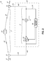
- a repeater 30 incorporates a receive antenna 32 (or donor antenna) for processing input signals 31 or input signals, indicated as in(t).
- the input in(t) signals 31 represent the input signals to be repeated, such as those that are transmitted from a source, such as a base station 12 (See Figure 1 ). Other sources might also be utilized to generate the input signals to be repeated.
- the feedback signals 34 are also shown in Figure 2 along with the repeated or transmit signals 37 from transmit antenna 36 (or coverage antenna).
- the repeated or transmit signals 37 illustrated in Figure 2 include the transmitted signals or signal portions that are directed to wireless devices, such as cell phones. As such, the feedback signals 34 reach the receive antenna 32.
- the combination of the input signals in(t) 31 and the feedback signals 34 are combined, in open space, and are received by the receive antenna 32 in an additive sense.
- the combined input signals in(t) 31 and feedback signals 34 form the receive signal or signals 38 that are the input signals for the repeater.
- the terms "signal” or “signals” are used interchangeably herein to refer to the signal(s) handled by the repeater and are not limited to just a single signal or plurality of signals.
- repeater 30 includes suitable electronics 40 coupled between the antennas 32, 36.
- such electronics will include adjustable gain circuitry 42 that provides a desired gain G in the repeater.
- frequency shift circuitry 44 provides the desired signal modification and frequency shift of the repeated signal in accordance with one aspect of the invention.
- Processing circuitry 46 is utilized to provide the desired gain margin measurement and to suitably adjust the gain G of the gain circuitry 42. To that end, processing circuitry 46 is appropriately coupled with the gain circuitry 42, and is also configured to receive a portion of the receive signal 38 and a portion 50 of the repeated signal 52 that is then transmitted by antenna 36 resulting in the transmit signal 37 and the feedback signal 34.
- the input or receive signal 38 progresses through repeater 30 to become the repeated signal 52.
- Repeated signal 52 experiences a delay (d) relative to the receive signal, which is considered the delay of the repeater.
- p propagation delay
- p propagation delay
- F feedback gain
- the block diagram of the Figures and the description herein generally illustrates a downlink signal path through the repeater 30, such as from a base station 12 to the mobile devices 24 (See Figure 1 ).
- a downlink signal path through the repeater 30, such as from a base station 12 to the mobile devices 24 (See Figure 1 ).
- similar uplink path components would be used in the repeater for the uplink direction. Therefore, the discussion herein regarding the downlink signal path also applies to the uplink path.
- the repeater circuitry 40 might process the signals in the analog domain in accordance with aspects of the invention so that the circuitry components 42, 44, and 46 provide the desired amplification or gain, modification (frequency shift), and processing in the analog domain, respectively.
- electronics 40 of the repeater might provide the various aspects of the invention in the digital domain.
- embodiments of the invention use combinations of digital and analog components.
- a return path such as an uplink path, would similarly process signals from the mobile device 24 back to the base station 12 in order to realize the invention.
- discussion of the signal processing in one path is made herein, with an understanding that generally the similar processing occurs and similar circuit components are used in the signal path in the opposite direction as well.
- the input signals or receive signals 38 are modified for decorrelation by being frequency-shifted, utilizing a frequency-shifting circuit 44 to provide transmission or repeated signals that are frequency-shifted from the input signals.
- the disclosed embodiment of the present invention utilizes an introduced frequency shift into the repeated signals and cross-correlation of the repeated signals with the receive signals in order to isolate the feedback signals from the input signals.
- One way to separately measure the input signal and the feedback signal is to autocorrelate the receive signal with itself. Since the feedback signal is essentially a delayed version of the input signal, the feedback signal will appear as a correlation peak at whatever time the feedback signal is delayed. If the correlation peak of the feedback signal is greater than the autocorrelation profile of the input signal, then the level of the feedback signal can be measured.
- This method has the advantage in that the gain margin can be measured while the repeater is operating. The method is most effective when the repeater delay is greater than 2-4 times the reciprocal of the modulation bandwidth of the repeated signals because then the feedback signal is delayed beyond that point where there is any significant autocorrelation due to the input signal itself.
- Such a methodology may be suitable for high bandwidth signals like CDMA and W-CDMA signals. However, narrowband signals have a very wide correlation bandwidth. Therefore, the autocorrelation profile of the input signal is wide relative to typical feedback delay of the repeater. Therefore, the autocorrelation profile masks the feedback signal.
- a small frequency shift is added to the output of the repeater, or is added to the repeated signals that are transmitted by the repeater.
- the frequency shift decorrelates the input signal and the feedback signal. This allows the level of the input signal and the feedback signal to be measured separately by cross-correlating the receive signal with the repeated signal.
- One advantage of the invention is that the gain margin may be measured while the repeater continues to operate and provide service. Furthermore, it provides suitable gain margin measurements even when the autocorrelation profile of the input signal is very wide, such as for narrowband signals.
- the frequency shift f shift is small so that it does not affect system performance significantly.
- the methodology of the invention operates based upon the fact that a wide sense stationary random signal cross-correlated with a frequency-shifted version of the same signal that has gone through any linear, time-invariant transformation has an average value of zero. Additionally, a wide sense stationary random signal multiplied by the complex conjugate of the same signal that has been frequency shifted and that has gone through any linear time invariant transformation has a phase that is uniformly distributed from -n to n with an average value of zero over integer periods of the frequency shift. This property implies that a correlation performed over integer periods of the frequency shift will have an average value of zero.
- This invention is applicable when the properties of the signals the repeater operates on, or repeats, are or can be transformed to be approximately similar to a wide sense stationary random signal over the measurement interval and when the forward and feedback path can be approximated as a linear, time invariant transform over the measurement interval.
- the cross-correlations are performed over exactly an integer number of periods of the frequency shift f shift to insure that the average cross-correlation phase is zero. Meeting that criterion, the invention minimizes the measurement period. If the measurement is performed over a non-integer number of periods, then the cross-correlation must be performed over a long enough time such that the average phase is still near zero.
- a frequency shift is provided to the repeated signal so that the gain margin may be measured by comparing the level of the input signal with the level of the feedback signal.
- the repeated signal output indicated as 37 is cross-correlated with the receive signal 38.
- the cross-correlation is performed over a time window that is greater than or equal to the maximum time delay of the feedback signal 34 relative to the input signal 31.
- the frequency shift provided to the output of the repeater or the repeated signal 37 is mathematically removed prior to the cross-correlation, and the resulting unshifted signal is cross-correlated with the receive signal 38.
- That cross-correlation is performed over a time window that is also greater than or equal to the maximum time delay of the feedback signal 34 relative to the input signal 31.
- the peak value of the cross-correlation is the relative level of the input signal.
- the gain margin is then calculated as the ratio of the relative level of the input signal to the relative level of the feedback signal.
- the input signal 31 is indicated as in(t), the repeater gain as "G”, the feedback gain as "F”, the repeater delay as "d”, and the propagation delay of the feedback signal from the transmit antenna 36 to the receive antenna 32 as "p".
- the frequency shift is indicated as f shift .
- the frequency shift is mathematically removed from the repeated signal 52 tx(t) prior to calculating the cross-correlation, and the unshifted repeated signal is then cross-correlated with the receive signal 38.
- the frequency shift can be mathematically removed by multiplying it with a complex exponential with the negative of the frequency shift as shown in Equation 3.
- tx unshift t tx t ⁇ e ⁇ j ⁇ 2 ⁇ ⁇ ⁇ fshift ⁇ t
- the ratio of the input and feedback signals is determined by other methodology that relies upon the fact that the input signal and feedback signal are decorrelated due to the applied frequency shift of the repeated signal.
- the average power of the receive signal can be calculated, rx rms 2 .
- the relative level of the feedback signal in the receive signal is then calculated as the cross-correlation of the receive signal with the receive signal shifted by the negative of the frequency shift provided by the transmission circuitry of the invention.
- the feedback signal in this case is represented as the delayed input signal multiplied by the loop gain of the repeater multiplied by the frequency shift, G ⁇ F ⁇ rx(t-d-p) ⁇ e j ⁇ 2 ⁇ fshift ⁇ t .
- the receive signal can then be represented as the sum of the input signal and the feedback signal as shown in Equation 5.
- rx t in t + G ⁇ F ⁇ rx t ⁇ d ⁇ p ⁇ e j ⁇ 2 ⁇ ⁇ ⁇ fshift ⁇ t
- the receive signal shifted by the negative of the frequency shift fshift is shown in Equation 6
- rx unshift t in t ⁇ e ⁇ j ⁇ 2 ⁇ ⁇ ⁇ fshift ⁇ t + G ⁇ F ⁇ rx t ⁇ d ⁇ p
- the cross correlation of rx(t) with rx shift (t) is equivalent to the sum of the input signal 31 in(t) with a negative frequency shift applied cross-correlated with the receive signal rx(t) and the feedback signal G ⁇ F ⁇ rx(t-d-p) cross correlated with rx(t).
- G and F are linear, time-invariant systems
- the cross correlation of in(t) ⁇ e -j ⁇ 2 ⁇ fshift ⁇ t with rx(t) will have an average value of zero because the signals are uncorrelated.
- the gain margin can then be calculated as the ratio of the average power of rx(t) to the cross-correlation of rx(t) and rx shift (t) as shown in Equation 7.
- rx rms 2 G ⁇ F ⁇ rx rms 2 1 G ⁇ F
- the correlation circuitry insures that the average phase of the cross-correlation is zero, while minimizing the number of computations. If the frequency shift is small and the bandwidth of the signal is very large, then the calculations are performed over a large number of samples. However, to minimize the number of computations, one embodiment of the invention performs a windowed cross-correlation. The windows are equally distributed throughout one period of the frequency shift f shift . For instance, if the frequency shift was one Hertz, the correlation would have to be performed over a one-second period. However, if a window were applied from 0 - 0.1 seconds and 0.5 - 0.6 seconds, then the average phase of the cross-correlations would still sum to zero. Generally, any number of windows can be used as long as the average phase of the cross-correlations equals zero.
- the correlation circuitry or processing circuitry assumes that the magnitude of the repeated signal is approximately constant throughout the measurement period. If the magnitude of the signal's envelope varies greatly during the measurement, the sum of the correlations may not add to zero.
- the receive and repeated/transmit signals are normalized so that they have a constant envelope prior to the correlation calculations. Normalization does not change the ratio of the input signal to the feedback signal. If the receive signal and repeated signal are normalized by the same function, the methodology of the invention continues to provide the desired results.
- one embodiment of the invention may provide a constant frequency shift that is always applied to the repeated signal.
- the frequency shift feature is selectable and may be selectively turned ON or OFF selectively as the gain margin measurement is needed.
- the frequency shift may be selectively varied both in the amount of the frequency shift, and also the sign of the shift.
- the invention may alternate between a positive frequency shift and a negative frequency shift so that the overall average frequency shift utilized in the invention is zero.
- the modulating or varying signal may be sinusoidal.
- any periodic function might be used to modulate the phase of the repeated signal. Therefore, the invention is not limited with respect to the selective variation of the frequency shift.
- repeater 30a incorporates a receive antenna 32 and transmit antenna 36 coupled with appropriate repeater circuitry 40a.
- the components are shown in a downlink path 60 in the repeater 30a. Similar components will exist in the uplink path 62 for handling uplink traffic between wireless devices and a base station for example. Accordingly, components within the downlink path 60 will be described herein in further detail with the assumption that similar functionality and components would be utilized in the uplink path 62.
- Receive antenna 32 receives both the input signal and frequency shifted or modified feedback signal. That receive signal is coupled to a low noise amplifier (LNA) 64 for amplifying downlink RF receive signals from a base station.
- LNA low noise amplifier
- a mixer component 66 is fed by an appropriate local oscillator (LO) signal and converts the RF receive signal 38 to an IF signal at a different IF frequency or a frequency at or near the baseband frequency for ease of later processing in the repeater.
- the signal is then filtered by a filter component or circuitry 68.
- the repeater circuitry incorporates both analog and digital components.
- Digital signal processing circuitry 70 is implemented for adjusting gain as well as for providing the necessary modification, such as a frequency shift f shift , to the repeater signal before it is transmitted as a repeated signal.
- an A/D converter circuit 72 converts the analog signal to an appropriate digital signal for further digital processing.
- the digital signal is sent to DSP circuitry 70 that might be an FPGA, digital signal processor or other such element.
- the DSP circuitry might include an additional digital mixer circuit 74 fed by a suitable numerically-controlled oscillator (NCO) signal to provide digital downconversion for ease of further processing.
- NCO numerically-controlled oscillator
- the signal might also be filtered by an appropriate digital filter 76. Filter 76 might also change the amplitude of the signal.
- Component 78 represents suitable circuitry for adjusting the gain within repeater 30a. Although as noted, the gain component might be implemented together with the filter 76.
- frequency-shifting circuitry 80 provides the desired frequency shift within the repeated signals in order to provide the proper decorrelation between the feedback signal 34 and the input signal 31.
- the signal has a frequency shift added by mixing it with the frequency shift oscillator.
- the signal might then be digitally upconverted by appropriate digital upconversion circuitry 82 fed by a transmit NCO. The signal may then be converted to back to an analog signal by D/A circuitry 84.
- the analog signal such as at analog IF, is further upconverted with mixer circuitry 86 fed by an appropriate transmit LO to an appropriate RF signal.
- the RF signal is filtered by filter circuitry 88, and then fed to an RF power amplifier 90 before being transmitted as a repeated signal through the transmit antenna 36.
- the mixing elements are typical of a repeater. There can be more or fewer mixing elements than illustrated in the examples and still implement a functional repeater.
- the frequency shift mixing operation can be combined with one or more of the other mixers if desired. However, the mixing operations must be implemented such that the frequency of the input signal and the frequency of the transmit or repeated signal differ by the amount of the frequency shift.
- the frequency shift mixer is shown after the filter; however, it can be placed anywhere between the receive and transmit antennas. In Figure 4 it is shown prior to the filter and/or gain block.
- the frequency shifting or translation might be implemented using a phase shifter rather than a mixer.
- a phase shifter may provide a desirable frequency translation in the analog domain.
- the frequency shifting/ translation is not limited to a particular element for providing the shifting in accordance with aspects of the invention.
- the noted correlation functionality is provided by suitable correlation circuit 100 within the digital signal processing (DSP) circuitry 70.
- the correlations to determine gain margin are performed by a capturing samples of the signal in the digital path and performing the described calculations.
- the capture point may be anywhere in the signal path, either before or after the frequency shift circuit because the circuit has the ability to add or remove the applied frequency shift by mathematical computation.
- the correlation circuit samples the receive signal 38 via suitable connections 102 and also is coupled to sample the frequency-shifted repeated signal in the repeater path as illustrated by the appropriate connection 104.
- Correlation circuit 100 may also provide the necessary functionality for automatically controlling the gain through the gain component 78 by way of line 106 based on the measured correlations and determined gain margin.
- Figure 4 illustrates a repeater 30b of the invention wherein the frequency shift circuitry 80 is positioned prior to the gain block or gain circuitry 78 within the repeater circuitry 40b.
- the frequency shift of the feedback signal 34 would be identical to the frequency shift of the repeated signals 37.
- the invention measures and accounts for the additional frequency shifting in the cross-correlation calculations. For example, this might be done by examining or measuring how the phase of the cross-correlation changes throughout the correlation period. By finding constant changes in the correlation phase during the correlation period, the phase change due to any additional frequency shift can be readily determined.
- the circuitry provides a compensating amount of frequency shift that is added or subtracted during the correlation calculation to negate the affect of any additional frequency shift associated with the environment and installation. This functionality will be implemented in the digital signal processing circuitry as suitable in the circuits of Figures 3 and 4 .
- the gain is automatically adjusted by the DSP circuitry 70, and specifically gain block or component 78.
- the gain may be automatically adjusted to ensure that the gain margin is above an acceptable level to insure proper operation.
- the gain margin might be adjusted through the DSP control circuitry as well as the specific gain adjustment parameters.
- the gain margin is usually greater than 0 dB in order to prevent oscillation. In fact, it is usually kept well above 0 dB to allow for variation in repeater gain, and antenna isolation.
- the present invention by constantly measuring the gain margin as noted herein, provides automatic gain adjustment so that the repeater can compensate for any variation in the gain margin.
- one embodiment of the invention might use a complex sinusoid to frequency shift the repeated signal that is output.
- other signals might be used to modify the repeated signals with respect to the received signal to thereby decorrelate the repeated signal from the receive signal. Such modification must have minimal affect on the repeated or transmitted output of the repeater.
- frequency shift and correlation calculations are implemented in the digital domain, such as through DSP circuitry 70.
- frequency shifting and decorrelation might also be implemented in the analog domain.
- a mixed signal implementation using both analog and digital components might be utilized to provide the desired signal decorrelation functions and correlation calculations.
- the decorrelating function applied to the repeated signal is a frequency shift
- the methods described herein could be readily adapted by a person of ordinary skill in the art to use alternate decorrelation functions to measure gain margin and control the gain of a repeater to maintain a minimum gain margin.
- the invention might be applied to any type of signal repeating system wherein some part of the transmitted or repeated signal is fed back or finds its way into the input on the receive side as a feedback signal.
Landscapes
- Engineering & Computer Science (AREA)
- Computer Networks & Wireless Communication (AREA)
- Signal Processing (AREA)
- Radio Relay Systems (AREA)
- Cable Transmission Systems, Equalization Of Radio And Reduction Of Echo (AREA)
Applications Claiming Priority (4)
| Application Number | Priority Date | Filing Date | Title |
|---|---|---|---|
| US12/635,887 US8948687B2 (en) | 2009-12-11 | 2009-12-11 | System and method for determining and controlling gain margin in an RF repeater |
| EP10791026.7A EP2510638B1 (de) | 2009-12-11 | 2010-12-07 | System und methode zum bestimmen und kontrollieren des verstärkungsabstandes in einem rf repeater |
| EP17163692.1A EP3206309B1 (de) | 2009-12-11 | 2010-12-07 | System und methode zum bestimmen und kontrollieren des verstärkungsabstandes in einem rf repeater |
| PCT/US2010/059198 WO2011071854A1 (en) | 2009-12-11 | 2010-12-07 | System and method for determining and controlling gain margin in an rf repeater |
Related Parent Applications (2)
| Application Number | Title | Priority Date | Filing Date |
|---|---|---|---|
| EP17163692.1A Division EP3206309B1 (de) | 2009-12-11 | 2010-12-07 | System und methode zum bestimmen und kontrollieren des verstärkungsabstandes in einem rf repeater |
| EP10791026.7A Division EP2510638B1 (de) | 2009-12-11 | 2010-12-07 | System und methode zum bestimmen und kontrollieren des verstärkungsabstandes in einem rf repeater |
Publications (1)
| Publication Number | Publication Date |
|---|---|
| EP3553970A1 true EP3553970A1 (de) | 2019-10-16 |
Family
ID=43499801
Family Applications (3)
| Application Number | Title | Priority Date | Filing Date |
|---|---|---|---|
| EP17163692.1A Not-in-force EP3206309B1 (de) | 2009-12-11 | 2010-12-07 | System und methode zum bestimmen und kontrollieren des verstärkungsabstandes in einem rf repeater |
| EP10791026.7A Active EP2510638B1 (de) | 2009-12-11 | 2010-12-07 | System und methode zum bestimmen und kontrollieren des verstärkungsabstandes in einem rf repeater |
| EP19175908.3A Withdrawn EP3553970A1 (de) | 2009-12-11 | 2010-12-07 | System und verfahren zur bestimmung und steuerung der amplitudenreserve bei einem hf-repeater |
Family Applications Before (2)
| Application Number | Title | Priority Date | Filing Date |
|---|---|---|---|
| EP17163692.1A Not-in-force EP3206309B1 (de) | 2009-12-11 | 2010-12-07 | System und methode zum bestimmen und kontrollieren des verstärkungsabstandes in einem rf repeater |
| EP10791026.7A Active EP2510638B1 (de) | 2009-12-11 | 2010-12-07 | System und methode zum bestimmen und kontrollieren des verstärkungsabstandes in einem rf repeater |
Country Status (6)
| Country | Link |
|---|---|
| US (2) | US8948687B2 (de) |
| EP (3) | EP3206309B1 (de) |
| CN (1) | CN102783052B (de) |
| ES (1) | ES2629310T3 (de) |
| PL (1) | PL2510638T3 (de) |
| WO (1) | WO2011071854A1 (de) |
Families Citing this family (10)
| Publication number | Priority date | Publication date | Assignee | Title |
|---|---|---|---|---|
| CN102948089B (zh) * | 2010-05-25 | 2016-01-20 | 爱立信(中国)通信有限公司 | 无线通信网络中的方法和装置 |
| US20130078907A1 (en) * | 2011-09-23 | 2013-03-28 | Qualcomm Incorporated | Per carrier gain control in a multi-carrier repeater |
| US8774708B2 (en) | 2011-11-10 | 2014-07-08 | Qualcomm Incorporated | Estimation of repeater loop delay for repeater gain control |
| CA2814303A1 (en) | 2013-04-26 | 2014-10-26 | Cellphone-Mate, Inc. | Apparatus and methods for radio frequency signal boosters |
| CN103595497B (zh) * | 2013-11-21 | 2016-08-17 | 三维通信股份有限公司 | 一种采用延迟转发实现手机信号屏蔽的系统及方法 |
| WO2016032659A1 (en) | 2014-08-26 | 2016-03-03 | Parsons Xtreme Golf, LLC | Golf club heads and methods to manufacture golf club heads |
| CN204578536U (zh) * | 2015-02-09 | 2015-08-19 | 福建京奥通信技术有限公司 | Fdd-lte直放站 |
| US9882613B2 (en) | 2015-06-01 | 2018-01-30 | Corning Optical Communications Wireless Ltd | Determining actual loop gain in a distributed antenna system (DAS) |
| EP3577797B1 (de) | 2017-01-31 | 2023-08-16 | Wilson Electronics, LLC | Reduzierung der schwingung in einem signalverstärker |
| WO2024087178A1 (zh) * | 2022-10-28 | 2024-05-02 | 华为技术有限公司 | 传感器系统及其方法 |
Citations (2)
| Publication number | Priority date | Publication date | Assignee | Title |
|---|---|---|---|---|
| EP0227393A2 (de) * | 1985-12-16 | 1987-07-01 | Nippon Telegraph And Telephone Corporation | Funkverstärkerstation mit Überlaufmessung |
| US20050215193A1 (en) * | 2001-11-12 | 2005-09-29 | Thomas Kummetz | Digital repeater having bandpass filtering, adaptive pre-equalization and suppression of natural oscillation |
Family Cites Families (59)
| Publication number | Priority date | Publication date | Assignee | Title |
|---|---|---|---|---|
| US3085200A (en) * | 1960-11-18 | 1963-04-09 | Bell Telephone Labor Inc | Timing for regenerative repeaters |
| US3086080A (en) * | 1961-06-14 | 1963-04-16 | Bell Telephone Labor Inc | Self-timed regenerative repeater for pcm |
| JPS50102218A (de) * | 1974-01-09 | 1975-08-13 | ||
| US4363129A (en) * | 1980-12-11 | 1982-12-07 | Motorola, Inc. | Method and means of minimizing simulcast distortion in a receiver when using a same-frequency repeater |
| US4383331A (en) * | 1981-07-02 | 1983-05-10 | Motorola, Inc. | Method and means of preventing oscillations in a same-frequency repeater |
| US4561067A (en) * | 1982-06-23 | 1985-12-24 | British Telecommunications | Multi-channel cross-talk interference reduction circuit using modulation-multiplying-demodulation correlator |
| US5040189A (en) * | 1987-01-12 | 1991-08-13 | Motorola, Inc. | Multiple frequency radio system employing pulse repeaters |
| US4845746A (en) * | 1987-06-23 | 1989-07-04 | Rockwell International Corporation | Echo canceller with relative feedback control |
| US5134464A (en) * | 1990-11-16 | 1992-07-28 | North American Philips Corporation | Method and apparatus for the transmission and reception of a multicarrier digital television signal |
| US5095528A (en) * | 1988-10-28 | 1992-03-10 | Orion Industries, Inc. | Repeater with feedback oscillation control |
| US5163044A (en) * | 1991-01-02 | 1992-11-10 | At&T Bell Laboratories | Use of a fractionally spaced equalizer to perform echo cancellation in a full-duplex modem |
| USD396455S (en) * | 1994-01-21 | 1998-07-28 | Xerox Corporation | Display object for a display screen |
| JP2713161B2 (ja) * | 1994-04-22 | 1998-02-16 | 日本電気株式会社 | 無線通信システム |
| US5790632A (en) * | 1994-09-30 | 1998-08-04 | Qualcom Incorporated | Method and apparatus for echo canceling accounting for companding induced quantization error |
| GB9423027D0 (en) * | 1994-11-15 | 1995-01-04 | Univ Bristol | Full-duplex radio transmitter/receiver |
| USD403673S (en) * | 1996-07-29 | 1999-01-05 | NetObjects, Inc. | Computer icon for a screen |
| USD395427S (en) * | 1996-07-29 | 1998-06-23 | NetObjects, Inc. | Computer icon for a display screen |
| US5974301A (en) * | 1996-09-18 | 1999-10-26 | Ludwig Kipp | Frequency cancelling system and method |
| US6253060B1 (en) * | 1996-12-20 | 2001-06-26 | Airnet Communications Corporation | Method and apparatus employing wireless remote loopback capability for a wireless system repeater to provide end-to-end testing without a wireline connection |
| US5835848A (en) * | 1996-12-30 | 1998-11-10 | Lucent Technologies Inc. | Range repeater for a transmission system |
| US6484012B1 (en) * | 1997-08-04 | 2002-11-19 | Wireless Facilities, Inc. | Inter-band communication repeater system |
| EP0905914A3 (de) | 1997-08-27 | 2000-04-05 | Shin-A Telecom | Gerät und Sendeempfänger mit Unterdrückung des Sendesignals an der Empfangsantenne |
| USD404386S (en) * | 1997-09-03 | 1999-01-19 | Cmsi | Icon for a display |
| JP3504470B2 (ja) * | 1997-09-18 | 2004-03-08 | 日本放送協会 | Afc回路、キャリア再生回路および受信装置 |
| USD432507S (en) * | 1997-11-05 | 2000-10-24 | The United States Of America As Represented By The Secretary Of The Army | Computer-generated image for a computer monitor |
| US6141531A (en) * | 1997-11-26 | 2000-10-31 | Direct Wireless Corporation | Local wireless communication system with external communications link |
| US6385176B1 (en) * | 1998-06-04 | 2002-05-07 | Lucent Technologies Inc. | Communication system based on echo canceler tap profile |
| USD438213S1 (en) * | 1998-11-23 | 2001-02-27 | Siemens Aktiengesellschaft | Graphical user interface for a medical monitor |
| US7423983B1 (en) * | 1999-09-20 | 2008-09-09 | Broadcom Corporation | Voice and data exchange over a packet based network |
| US6731904B1 (en) * | 1999-07-20 | 2004-05-04 | Andrew Corporation | Side-to-side repeater |
| KR100379378B1 (ko) * | 1999-09-13 | 2003-04-10 | 엘지전자 주식회사 | 중계국 시스템의 송수신장치 |
| US6940893B1 (en) * | 1999-09-27 | 2005-09-06 | Telecommunications Research Laboratories | High-speed indoor wireless chirp spread spectrum data link |
| US6697603B1 (en) * | 1999-12-13 | 2004-02-24 | Andrew Corporation | Digital repeater |
| ES2160087B1 (es) * | 2000-02-18 | 2003-03-01 | Mier Comunicaciones S A | Procedimiento para la repeticion de señales en insofrecuencia y repetidor de señales en isofrecuencia. |
| USD448777S1 (en) * | 2000-04-06 | 2001-10-02 | Morecom, Inc. | User interface icon for a computer screen |
| US6385435B1 (en) * | 2000-04-20 | 2002-05-07 | Jhong Sam Lee | Coupled interference concellation system for wideband repeaters in a cellular system |
| US6501955B1 (en) * | 2000-06-19 | 2002-12-31 | Intel Corporation | RF signal repeater, mobile unit position determination system using the RF signal repeater, and method of communication therefor |
| US6539204B1 (en) * | 2000-09-29 | 2003-03-25 | Mobilian Corporation | Analog active cancellation of a wireless coupled transmit signal |
| US7088953B2 (en) | 2000-10-18 | 2006-08-08 | Spotwave Wireless Canada Inc. | Coverage area signature in an on-frequency repeater |
| US6915112B1 (en) * | 2000-11-12 | 2005-07-05 | Intel Corporation | Active cancellation tuning to reduce a wireless coupled transmit signal |
| US6831900B2 (en) * | 2001-02-09 | 2004-12-14 | Agere Systems Inc. | Filter cell, method of deriving an echo component and an echo canceling system employing the same |
| JP2002271241A (ja) * | 2001-03-06 | 2002-09-20 | Matsushita Electric Ind Co Ltd | 中継装置 |
| US20020191779A1 (en) * | 2001-03-23 | 2002-12-19 | Tien Pham | System for convolutional echo cancellation by iterative autocorrelation |
| US7133442B2 (en) * | 2001-03-29 | 2006-11-07 | Hewlett-Packard Development Company, L.P. | Rapid identification of transmission media channel characteristics |
| NO314109B1 (no) * | 2001-04-20 | 2003-01-27 | Radionor Comm As | Apparat for kapasitetsökning mellom sendere og mottakere i kortholds trådlöse kommunikasjonsnettverk, spesielt i ISM frekvensbånd |
| US20040014438A1 (en) * | 2002-06-20 | 2004-01-22 | Abraham Hasarchi | System and method for excluding narrow band noise from a communication channel |
| US7460831B2 (en) * | 2002-06-20 | 2008-12-02 | Dekolink Wireless Ltd. | System and method for excluding narrow band noise from a communication channel |
| US7355993B2 (en) * | 2002-06-27 | 2008-04-08 | Adkins Keith L | Method and apparatus for forward link gain control in a power controlled repeater |
| US7200134B2 (en) * | 2002-10-01 | 2007-04-03 | Widefi, Inc. | Wireless area network using frequency translation and retransmission based on modified protocol messages for enhancing network coverage |
| US7546084B2 (en) * | 2002-10-16 | 2009-06-09 | Andrew Llc | System and method of operation for network overlay geolocation system with repeaters |
| US7035321B2 (en) * | 2002-11-20 | 2006-04-25 | Spotwave Wireless Canada, Inc. | Monitoring stability of an on-frequency repeater |
| US7558575B2 (en) * | 2003-07-24 | 2009-07-07 | Motorola Inc. | Method and apparatus for wireless communication in a high velocity environment |
| US7558528B2 (en) * | 2003-07-31 | 2009-07-07 | Microsoft Corporation | Wireless local area network translating bi-directional packet repeater |
| BRPI0414099A (pt) * | 2003-09-03 | 2006-10-31 | Behzad Mohebbi | impulsionador celular de faixa curta |
| US7596352B2 (en) * | 2004-08-23 | 2009-09-29 | Samsung Electronics Co., Ltd. | Apparatus and method for channel estimation and echo cancellation in a wireless repeater |
| US20070161347A1 (en) * | 2006-01-10 | 2007-07-12 | Lucent Technologies, Inc. | Enabling a digital wireless service for a mobile station across two different wireless communications environments |
| BRPI0715908A2 (pt) | 2006-09-01 | 2014-03-18 | Qualcomm Inc | Repetidor possuindo configuração de antena receptora e transmissora dual com adaptação para maior isolamento |
| JP5133401B2 (ja) * | 2007-04-26 | 2013-01-30 | ドルビー・インターナショナル・アクチボラゲット | 出力信号の合成装置及び合成方法 |
| US8358969B2 (en) * | 2009-05-11 | 2013-01-22 | Qualcomm Incorporated | Feedback delay control in an echo cancellation repeater |
-
2009
- 2009-12-11 US US12/635,887 patent/US8948687B2/en not_active Ceased
-
2010
- 2010-12-07 EP EP17163692.1A patent/EP3206309B1/de not_active Not-in-force
- 2010-12-07 EP EP10791026.7A patent/EP2510638B1/de active Active
- 2010-12-07 PL PL10791026T patent/PL2510638T3/pl unknown
- 2010-12-07 ES ES10791026.7T patent/ES2629310T3/es active Active
- 2010-12-07 EP EP19175908.3A patent/EP3553970A1/de not_active Withdrawn
- 2010-12-07 CN CN201080056179.2A patent/CN102783052B/zh not_active Expired - Fee Related
- 2010-12-07 WO PCT/US2010/059198 patent/WO2011071854A1/en not_active Ceased
-
2017
- 2017-02-03 US US15/424,631 patent/USRE47075E1/en active Active
Patent Citations (2)
| Publication number | Priority date | Publication date | Assignee | Title |
|---|---|---|---|---|
| EP0227393A2 (de) * | 1985-12-16 | 1987-07-01 | Nippon Telegraph And Telephone Corporation | Funkverstärkerstation mit Überlaufmessung |
| US20050215193A1 (en) * | 2001-11-12 | 2005-09-29 | Thomas Kummetz | Digital repeater having bandpass filtering, adaptive pre-equalization and suppression of natural oscillation |
Also Published As
| Publication number | Publication date |
|---|---|
| ES2629310T3 (es) | 2017-08-08 |
| EP2510638B1 (de) | 2017-04-12 |
| CN102783052A (zh) | 2012-11-14 |
| EP3206309B1 (de) | 2019-05-29 |
| US8948687B2 (en) | 2015-02-03 |
| USRE47075E1 (en) | 2018-10-02 |
| EP2510638A1 (de) | 2012-10-17 |
| WO2011071854A1 (en) | 2011-06-16 |
| CN102783052B (zh) | 2015-09-30 |
| US20110143658A1 (en) | 2011-06-16 |
| PL2510638T3 (pl) | 2017-09-29 |
| EP3206309A1 (de) | 2017-08-16 |
Similar Documents
| Publication | Publication Date | Title |
|---|---|---|
| EP3206309B1 (de) | System und methode zum bestimmen und kontrollieren des verstärkungsabstandes in einem rf repeater | |
| EP2382720B1 (de) | Schaltung und methode zur rückkopplungsunterdrückung in repeatern | |
| EP2158711B1 (de) | Gleichfrequenzverstärker mit agc-stabilitätsbestimmung | |
| CN102907012B (zh) | 在信号中继系统中检测和测量上行链路流量的系统和方法 | |
| US8155303B2 (en) | System and method for cancelling echo | |
| US20100118922A1 (en) | Wireless repeater apparatus for canceling interference signal | |
| EP1039716B1 (de) | Zwischenverstärker eines OFDM-Übertragungssignals und Empfänger | |
| US8081945B2 (en) | Feedback cancellation system and method | |
| JP5171529B2 (ja) | 中継送受信装置 | |
| US20190097674A1 (en) | Device and method for reducing the self-interference signal in a full-duplex communication system | |
| EP3998715B1 (de) | Vorrichtung und verfahren zur einstellung der verstärkung eines hochfrequenzverstärkers unter verwendung eines synchronisationssignals | |
| WO2008108528A1 (en) | Wireless repeater apparatus for canceling interference signal | |
| US20060034351A1 (en) | Monitoring stability of an on-frequency repeater | |
| KR200407860Y1 (ko) | 원하지 않는 간섭신호의 검출 및 제거장치 | |
| KR100843702B1 (ko) | 디지털신호처리를 이용하여 간섭신호를 제거하기 위한시스템 | |
| KR20050004708A (ko) | 무선 통신 시스템의 발진 제어 중계 장치 | |
| JP2023122192A (ja) | 増幅装置、無線装置、及び監視方法 | |
| KR100605673B1 (ko) | 원하지 않는 간섭신호의 검출 및 제거장치 | |
| KR20070071567A (ko) | 간섭신호 제거 기능을 갖는 무선 중계 시스템 | |
| JPH044620A (ja) | 送信電力制御装置 |
Legal Events
| Date | Code | Title | Description |
|---|---|---|---|
| PUAI | Public reference made under article 153(3) epc to a published international application that has entered the european phase |
Free format text: ORIGINAL CODE: 0009012 |
|
| STAA | Information on the status of an ep patent application or granted ep patent |
Free format text: STATUS: THE APPLICATION HAS BEEN PUBLISHED |
|
| AC | Divisional application: reference to earlier application |
Ref document number: 3206309 Country of ref document: EP Kind code of ref document: P Ref document number: 2510638 Country of ref document: EP Kind code of ref document: P |
|
| AK | Designated contracting states |
Kind code of ref document: A1 Designated state(s): AL AT BE BG CH CY CZ DE DK EE ES FI FR GB GR HR HU IE IS IT LI LT LU LV MC MK MT NL NO PL PT RO RS SE SI SK SM TR |
|
| STAA | Information on the status of an ep patent application or granted ep patent |
Free format text: STATUS: REQUEST FOR EXAMINATION WAS MADE |
|
| 17P | Request for examination filed |
Effective date: 20200416 |
|
| RBV | Designated contracting states (corrected) |
Designated state(s): AL AT BE BG CH CY CZ DE DK EE ES FI FR GB GR HR HU IE IS IT LI LT LU LV MC MK MT NL NO PL PT RO RS SE SI SK SM TR |
|
| STAA | Information on the status of an ep patent application or granted ep patent |
Free format text: STATUS: EXAMINATION IS IN PROGRESS |
|
| 17Q | First examination report despatched |
Effective date: 20210728 |
|
| STAA | Information on the status of an ep patent application or granted ep patent |
Free format text: STATUS: THE APPLICATION HAS BEEN WITHDRAWN |
|
| 18W | Application withdrawn |
Effective date: 20230906 |