EP3553941A1 - Fotovoltaikmodul ohne rahmen und herstellungsverfahren eines solchen moduls - Google Patents
Fotovoltaikmodul ohne rahmen und herstellungsverfahren eines solchen moduls Download PDFInfo
- Publication number
- EP3553941A1 EP3553941A1 EP19168707.8A EP19168707A EP3553941A1 EP 3553941 A1 EP3553941 A1 EP 3553941A1 EP 19168707 A EP19168707 A EP 19168707A EP 3553941 A1 EP3553941 A1 EP 3553941A1
- Authority
- EP
- European Patent Office
- Prior art keywords
- spacer
- laminated structure
- photovoltaic
- collet
- layer
- Prior art date
- Legal status (The legal status is an assumption and is not a legal conclusion. Google has not performed a legal analysis and makes no representation as to the accuracy of the status listed.)
- Granted
Links
Images

Classifications
-
- H—ELECTRICITY
- H02—GENERATION; CONVERSION OR DISTRIBUTION OF ELECTRIC POWER
- H02S—GENERATION OF ELECTRIC POWER BY CONVERSION OF INFRARED RADIATION, VISIBLE LIGHT OR ULTRAVIOLET LIGHT, e.g. USING PHOTOVOLTAIC [PV] MODULES
- H02S20/00—Supporting structures for PV modules
- H02S20/20—Supporting structures directly fixed to an immovable object
- H02S20/22—Supporting structures directly fixed to an immovable object specially adapted for buildings
-
- H—ELECTRICITY
- H02—GENERATION; CONVERSION OR DISTRIBUTION OF ELECTRIC POWER
- H02S—GENERATION OF ELECTRIC POWER BY CONVERSION OF INFRARED RADIATION, VISIBLE LIGHT OR ULTRAVIOLET LIGHT, e.g. USING PHOTOVOLTAIC [PV] MODULES
- H02S20/00—Supporting structures for PV modules
- H02S20/10—Supporting structures directly fixed to the ground
-
- Y—GENERAL TAGGING OF NEW TECHNOLOGICAL DEVELOPMENTS; GENERAL TAGGING OF CROSS-SECTIONAL TECHNOLOGIES SPANNING OVER SEVERAL SECTIONS OF THE IPC; TECHNICAL SUBJECTS COVERED BY FORMER USPC CROSS-REFERENCE ART COLLECTIONS [XRACs] AND DIGESTS
- Y02—TECHNOLOGIES OR APPLICATIONS FOR MITIGATION OR ADAPTATION AGAINST CLIMATE CHANGE
- Y02B—CLIMATE CHANGE MITIGATION TECHNOLOGIES RELATED TO BUILDINGS, e.g. HOUSING, HOUSE APPLIANCES OR RELATED END-USER APPLICATIONS
- Y02B10/00—Integration of renewable energy sources in buildings
- Y02B10/10—Photovoltaic [PV]
-
- Y—GENERAL TAGGING OF NEW TECHNOLOGICAL DEVELOPMENTS; GENERAL TAGGING OF CROSS-SECTIONAL TECHNOLOGIES SPANNING OVER SEVERAL SECTIONS OF THE IPC; TECHNICAL SUBJECTS COVERED BY FORMER USPC CROSS-REFERENCE ART COLLECTIONS [XRACs] AND DIGESTS
- Y02—TECHNOLOGIES OR APPLICATIONS FOR MITIGATION OR ADAPTATION AGAINST CLIMATE CHANGE
- Y02E—REDUCTION OF GREENHOUSE GAS [GHG] EMISSIONS, RELATED TO ENERGY GENERATION, TRANSMISSION OR DISTRIBUTION
- Y02E10/00—Energy generation through renewable energy sources
- Y02E10/50—Photovoltaic [PV] energy
Definitions
- the present invention relates to a frameless photovoltaic module whose structure is maintained by means of one or more spacers.
- the invention also relates to a method of manufacturing such a photovoltaic module.
- the invention has applications in the field of solar energy and, in particular, in the field of photovoltaic modules.
- a photovoltaic module also called photovoltaic panel, comprises a plurality of photovoltaic cells of the same type of technology, adapted to transform the light radiation from the sun into electrical energy.
- a photovoltaic cell in particular a silicon-based photovoltaic cell such as a homojunction or heterojunction photovoltaic cell
- the photogenerated charge carriers which contribute to the generation of the electric current in the photovoltaic cell, are collected by means of a an electrode array deposited on at least one of the two faces of the cell, generally on the one hand on the face which directly receives the light radiation, called the front face and on the other hand on the rear face.
- a photovoltaic cell can be monofacial or bifacial. In the case of a monofacial cell, only the front face of the cell receives the light radiation; the back side is usually covered with a solid metal layer. In the case of a bifacial cell, the front face receives the direct light radiation (coming directly from the light source) and the rear face receives the reflected light radiation.
- the photovoltaic cells are connected together, in series and / or in parallel, and form a set 110 of photovoltaic cells interconnected which collects the electrical energy produced by each of the cells.
- the photovoltaic cells are connected to each other via junction connectors 150 implanted under the rear face of the photovoltaic module 500 or on the sides of said module, for example in a frame 140 surrounding said module when a frame exists .
- the multilayer assembly comprising the set 110 of interconnected photovoltaic cells, the encapsulation layers 130 and the protective layers 120, 125 is laminated and called laminated structure 100.
- this laminated structure 100 is supported by a metal frame 140, generally aluminum, which allows the attachment of said laminated structure.
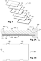
- the metal frame being one of the most expensive elements of the photovoltaic module - after the photovoltaic cells - manufacturers of photovoltaic modules have chosen to remove this metal frame and use clamps 200 to fix the photovoltaic modules 500 to their support, as shown on Figures 2A and 2B .
- one or more clamps 200 are mounted at the edge of the laminated structure 100 so as to exert a transverse force on all the laminated layers.
- each clamp 200 is mounted around a stop 160 of the laminated structure 100 and sandwich said laminated structure.
- clamps 200 allow, by pressing the jaws on the front and rear faces of the laminated structure 100, to maintain said laminated structure in a predetermined position and to fix it on a support or other photovoltaic module, as shown in FIGS. examples of Figures 3A and 3B .
- the applicant proposes to insert at least partially in the laminated structure a spacer for connecting said laminated structure and the collet.
- This photovoltaic assembly is characterized in that it furthermore comprises at least one clamping clamp mounted on the edge of the laminated structure and at least one spacer inserted at least partially in the rolled structure and comprising means intended to make it integral with said clamp.
- This photovoltaic assembly allows a solidarity of the laminated structure with the clamp so that the laminated structure can not detach from said clamp even in the presence of high stresses.
- frameless photovoltaic module will be included in the description as a photovoltaic module that does not include a metal frame intended, in general, to fix said photovoltaic module to a chassis.
- the first face of the set of photovoltaic cells will be called indifferently front face of the set of photovoltaic cells, since it is the face which receives priority light radiation.
- the second face of the set of photovoltaic cells will be referred to indifferently rear face of the set of photovoltaic cells.
- the spacer has a laminated first end within the laminate structure. These embodiments provide a relatively simple insertion of the spacer into the laminate structure.
- the first end of the spacer is inserted into the layer of encapsulating material.
- This first end of the spacer may advantageously be positioned in a plane parallel to the assembly encapsulating the plurality of photovoltaic cells.
- the plane of the laminated structure and therefore the plane of each of the layers of said laminated structure, is the plane in which the largest dimensions of the laminated structure extend, namely the plane which is perpendicular to the dimension containing the thickness of said structure.
- the terms "transverse” or “transversely” mean through the plane of the laminated structure, that is to say according to the dimension containing the thickness of said structure.
- the spacer is a blade. At least part of this blade, for example that inserted into the laminated structure, may include orifices ensuring good encapsulation in the layer of encapsulating material.
- the spacer has a first end traversing transversely at least a portion of the laminated structure.
- the spacer is a rod.
- This rod may be of round, oval, rectangular or polygonal section.
- the spacer may comprise a second end intended to be locked in the collet.
- the first end of the spacer completely traverses the laminated structure in its thickness so that the spacer is able to be clamped between two jaws of the collet. In this way, the collet is inseparable from the laminated structure.
- first end of the rod will also be called the front end of the rod or inner end and the second end of the rod will be called the rear end or outer end.
- the mounting of the photovoltaic module may comprise an installation operation of at least one clamping clamp at the edge of said laminated structure so that the spacer solidarises the laminated structure with the clamping collet.
- the first end of the spacer is inserted into one of the layers of encapsulating material prior to lamination.
- At least part of the multilayer assembly is pierced transversely before lamination and before insertion of the spacer.
- the photovoltaic module comprises an additional step consisting in plugging at least one opening made during the lamination step with parts coated with a poorly adherent polytetrafluoroethylene (PTFE) coating facilitating their removal after lamination.
- PTFE polytetrafluoroethylene
- At least part of the multilayer assembly is pierced transversely after lamination and before insertion of the spacer.
- the second end of the spacer is locked in the collet.
- This photovoltaic module 500 comprises a laminated structure 100, or multilayer assembly, of the type described in the state of the art.
- This laminated structure 100 comprises a set 110 of photovoltaic cells having a front face and a rear face each covered with a layer 130 of a transparent encapsulant material and a protective layer 120, 125.
- the protective layer 120 forming the front face 100a of the laminated structure 100 is generally a protective layer of glass.
- the protective layer 125 forming the rear face 100b of the laminated structure 100 may also be a glass layer, for example when the photovoltaic module is bifacial or a layer of polymer, for example white or opaque, incorporating or not a foil aluminum, especially when the photovoltaic module is monofacial.
- the photovoltaic module 500 can be held by means of clamps 200 as shown in FIG. figure 4 .
- the photovoltaic module 500 and the clamps 200 form a photovoltaic assembly.
- the clamps 200 may be of a conventional type, such as those described in the state of the art, or a type specific to the invention as described below.
- the collets 200 may be separate clamps mounted on the laminated structure 100 and intended to be fixed on a support or a frame.
- the collets 200 may also be an integral part of the support or the frame and allow direct attachment of the laminated structure on said support or frame.
- the photovoltaic module 500 comprises spacers 300 each providing an integral connection between the laminated structure 100 and one of the clamping clamps 200.
- spacers 300 and four collets 200 are shown, it being understood that their number may vary from one to more than four depending on the applications, the support on which the photovoltaic module is to be fixed, the dimensions of the laminated structure and dimensions of the collets.
- each spacer 300 comprises a first section integrated in the laminated structure 100 and a second section secured to the collet 200
- the first section may be an end of the spacer or, on the contrary, the central portion of said spacer and the second section may be, respectively, a second end of the spacer or each of the ends. of said spacer.
- the second section is secured to the collet 200 by various techniques for blocking said second section in the collet or securing said second section on the collet to prevent any moving said second section, and therefore the spacer, relative to the collet.
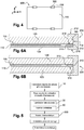
- the photovoltaic module of the invention may be manufactured according to a manufacturing method, an example of which is shown in FIG. figure 5 .
- This manufacturing method may include, for example, an operation 10 for manufacturing photovoltaic cells and interconnecting these cells in order to obtain an assembly 110 of interconnected photovoltaic cells.
- a protective layer 120, 125 is then deposited on the front face and on the rear face of the set of photovoltaic cells with, interposed between the set of photovoltaic cells and each protective layer, at least one layer. 130 of a transparent encapsulant material.
- Two layers of encapsulating material 130 may be deposited, one on the front face of the set of photovoltaic cells and the other on the rear face of the set of photovoltaic cells, the two layers merging in the step of lamination in a single layer in locations devoid of photovoltaic cells, such as on the outline of the set of photovoltaic cells.
- the various layers are laminated to form a laminated structure 100 and a spacer 300 is inserted at least partially into said laminated structure.
- the various layers 110-130 are laminated in a step 30 and then the spacer 300 is inserted into the laminated structure during a step 40.
- a portion of the spacer 300 is introduced within the layers (step 40) before the set of layers 110-130 is laminated.
- the step 40 for inserting the spacer can take place before the step 30 of lamination of the layers or, conversely, after the step 30 of lamination of the layers, as explained in detail thereafter.
- the collet 200 can be mounted around the edge 160 of the laminated structure 100, that is to say on the edge of said laminated structure, so as to sandwiching all the laminated layers 110-130 and at least a portion of the spacer 300. If several clamps 200 are provided, the mounting of the photovoltaic module 500 is finished when all the collets have been installed on the periphery of the laminated structure 100 and all the struts are secured to said clamps. The photovoltaic module 500 secured to the clamps 200 via the spacers 300 then constitutes a photovoltaic assembly.
- the spacer 300 may be a plate or a blade 310, for example of polymer or metal, inserted totally or only partially within the laminated layers.
- a first end of the spacer 300 is inserted into the laminated structure 100, the second end of the spacer being locked in the collet 200.
- the blade 310 is inserted entirely in the layer of encapsulating material 130, in the same plane or a plane parallel to the XZ plane containing the layer 110 of the photovoltaic cells so that the first end 313 - or inner end - of the blade 310 is not in contact with the layer 110 of photovoltaic cells.
- the blade 310 may have a thickness of a few hundred microns, for example 600 microns, and be housed in the layer 130 of encapsulating material with a thickness typically between 0.8 and 1.2 mm. It may also have a difference in thickness between the portion 310a intended to be laminated within the layers 110-130 and the portion 310b intended to be outside the laminated structure 100, the latter being up to 10mm for example.
- the blade 310 is inserted into the encapsulating material between the first protective glass layer 120 and the second polymer protective layer 125.
- the blade 310 is inserted into the encapsulating material between the first glass protective layer 120 and the second glass protective layer 125.
- the second end 312 - or outer end - located in the vicinity of the edge 160 of the laminated structure 100 is locked in the collet 200.
- the term "block" any technique to prevent a displacement of the second end relative to the laminated structure.
- the blocking can be obtained by clamping the spacer between two elements or by fixing by means of conventional fastening techniques, such as by gluing, welding or soldering or by mechanical fastening of the type screw / nut or bolt.
- fastening means can be combined, such as a bonding attachment combined with a screw fixing
- the outer end 312 of the spacer 300 may be an integral part of the clamp 200; in this case, the clamp 200 may comprise an element projecting between the jaws 212 and 216 of the clamp 200, which takes the form of a blade 310. The outer end of the spacer is then blocked by its design on the collet.
- the blade 310 forming the spacer 300 may be of rectangular shape or of any other polygonal shape such as a square or diamond shape. It may comprise a flat surface or, on the contrary, rough in order to increase the adhesion with the layer of encapsulating material 130.
- the roughness, on the front face and / or the rear face of the blade, can be for example between 0.8 and 50 ⁇ m.
- the blade 310, smooth or rough may also include one or more orifices 340, as shown in FIG. figure 8 , extending in all or part of the thickness of the blade. These orifices may have identical or different diameters that can extend up to about 1 cm.
- the portion 310a of the blade 310 to be laminated within the layers 110-130 contains orifices 340, the portion 310b located outside the laminated structure 100 can be full, without orifices.
- the spacer 300 is a staircase shaped blade whose section has a double L shape.
- the spacer 300 comprises a first blade portion 310 intended to be inserted into the laminated structure 100 a second blade portion 320 for attachment in the chuck 200, for example in an opening 220, and a third blade portion 330 connecting the first and second blade portions.
- the first and second blade portions 310, 320 are in the plane or a plane parallel to the XZ plane containing the layer 110 of the photovoltaic cells, while the third blade portion 330 is in a plane YZ substantially perpendicular to the XZ plane.
- This staircase shape allows the spacer 300 to conform to the shape of the laminated structure 100 so as not to exert excessive stress on the glass protection layer (s) 120, 125 during the operation of lamination.
- each blade 310 is described as providing a mechanical connection between the laminated structure 100 and the collet 200. However, it will be understood that a plurality of blades 310 can connect the laminated structure 100 to one and the same collet 200, the blades 310 being positionable parallel to each other in the XZ plane or the YZ plane.
- the spacer 300 is inserted after lamination, as shown in FIG. figure 5 .
- the spacer 300 is a transverse element 350 of polymer or metal, such as a rod or a rod, of parallelepipedal or cylindrical shape, with a circular, triangular, hexagonal or other section.
- This transverse element 350 hereinafter referred to as the rod 350, is intended to be introduced into an orifice 180 partially or completely traversing the rolled structure 100 in its thickness e.
- the rod 350 transversely crosses only part of the layers of the laminated structure 100. It crosses in particular the rear protective layer 125 and the layer of encapsulating material 130. It does not pass through the protective layer of glass, 120
- the rod 350 extends from the rear jaw 216 of the collet 200 to the layer of encapsulating material 130, the leading end 350a of the rod 350 being housed in said layer of encapsulating material 130 the rear end 350b being locked in the jaw 216 by clamping the collet 200 around the edge 160 of the laminated structure 100 and the rod 350 or fixed in the jaw 216 by one or more of the fastening means such as those described above with reference to Figures 6A-6B .
- FIG. Figure 9A ensures a good mechanical strength of the collet while maintaining a standard glass protection layer.
- the central part of the spacer 300 is inserted into the laminated structure 100, each end of said spacer 300 being locked in the collet 200.
- the rod 350 transversely traverses the whole of the laminated structure 100. In particular, it passes through the rear protective layer 125, made of polymer in the case of the Figure 9B or glass in the case of the Figure 9C as well as the layer of encapsulating material 130 and the protective layer before 120.
- the rod 350 extends between the rear jaw 216 and the front jaw 212 of the collet 200, passing through the laminated structure 100 from one side.
- the method of manufacturing a photovoltaic module then comprises an additional step of plugging the openings made with parts covered with a low adherence coating of the polytetrafluoroethylene type (PTFE) facilitating their removal after lamination.
- PTFE polytetrafluoroethylene type
- the rod 350 is introduced into said structure.
- the collet 200 is then placed and clamped around the edge 160 of the laminated structure so as to lock said shaft 350.
- the shaft 350 may also be attached to the rear jaw 216 and / or the front jaw 212 by one or several of the fixing means described above with reference to Figures 6A-6B .
- the embodiments of the Figures 9B and 9C allow to further improve the mechanical strength of the collet around the laminated structure, said collet can not be detached from the laminated structure.
- the rod 350 is described as providing a mechanical connection between the laminated structure 100 and the collet 200. However, it will be understood that several rods 350 can connect the laminated structure 100 to one and the same collet 200 , the rods 350 being positioned in directions substantially parallel to each other.
- the spacer 300 In the case where an electrical contact with the spacer 300 is possible (directly or via the collet if it is electrically conductive), it is in the form of blade 310 or rod 350, if the spacer 300 is conductive electrical, especially when made of metal, the spacer 300 is positioned at a distance from the photovoltaic cells and their interconnections (in particular metal ribbons) so as not to generate a short circuit between the internal connections of the assembly of photovoltaic cells and said spacer.
- a minimum distance for example of 10 mm in the case of category I materials and a photovoltaic system of 1000 V, must be respected between the positioning of a metal spacer 300 and the set of photovoltaic cells; the distance is at least 2mm if the insulating adhesive material between the front face and the back face can be considered as a glue joint (IEC 61730-1: 2016 standard).
- the photovoltaic module according to the invention comprises various variants, modifications and improvements which will become obvious to those skilled in the art, it being understood that these variants, modifications and improvements are within the scope of the invention.
Landscapes
- Engineering & Computer Science (AREA)
- Architecture (AREA)
- Civil Engineering (AREA)
- Structural Engineering (AREA)
- Photovoltaic Devices (AREA)
Applications Claiming Priority (1)
| Application Number | Priority Date | Filing Date | Title |
|---|---|---|---|
| FR1853215A FR3080242B1 (fr) | 2018-04-12 | 2018-04-12 | Module photovoltaique sans cadre et procede de fabrication d’un tel module |
Publications (2)
| Publication Number | Publication Date |
|---|---|
| EP3553941A1 true EP3553941A1 (de) | 2019-10-16 |
| EP3553941B1 EP3553941B1 (de) | 2021-05-26 |
Family
ID=63014698
Family Applications (1)
| Application Number | Title | Priority Date | Filing Date |
|---|---|---|---|
| EP19168707.8A Active EP3553941B1 (de) | 2018-04-12 | 2019-04-11 | Fotovoltaikmodul ohne rahmen und herstellungsverfahren eines solchen moduls |
Country Status (2)
| Country | Link |
|---|---|
| EP (1) | EP3553941B1 (de) |
| FR (1) | FR3080242B1 (de) |
Citations (3)
| Publication number | Priority date | Publication date | Assignee | Title |
|---|---|---|---|---|
| EP2267793A1 (de) * | 2009-06-22 | 2010-12-29 | L & T Partners | Befestigungsvorrichtung für ein Paneel |
| US20160365827A1 (en) * | 2015-06-09 | 2016-12-15 | Nextracker Inc. | Frameless solar module mounting |
| US20170163210A1 (en) * | 2015-12-08 | 2017-06-08 | Lee Gorny | Photovoltaic module |
-
2018
- 2018-04-12 FR FR1853215A patent/FR3080242B1/fr not_active Expired - Fee Related
-
2019
- 2019-04-11 EP EP19168707.8A patent/EP3553941B1/de active Active
Patent Citations (3)
| Publication number | Priority date | Publication date | Assignee | Title |
|---|---|---|---|---|
| EP2267793A1 (de) * | 2009-06-22 | 2010-12-29 | L & T Partners | Befestigungsvorrichtung für ein Paneel |
| US20160365827A1 (en) * | 2015-06-09 | 2016-12-15 | Nextracker Inc. | Frameless solar module mounting |
| US20170163210A1 (en) * | 2015-12-08 | 2017-06-08 | Lee Gorny | Photovoltaic module |
Also Published As
| Publication number | Publication date |
|---|---|
| EP3553941B1 (de) | 2021-05-26 |
| FR3080242B1 (fr) | 2022-01-14 |
| FR3080242A1 (fr) | 2019-10-18 |
Similar Documents
| Publication | Publication Date | Title |
|---|---|---|
| EP3118920B1 (de) | Selbsttragende dünnschicht-batterie, und herstellungsverfahren einer solchen batterie | |
| EP2510553B1 (de) | Pv-zelle, verfahren zur montage mehrerer zellen und anordnung aus mehreren pv-zellen | |
| EP1586122B1 (de) | Photovoltaisches modul mit aussenanschlussklemmen | |
| EP4002491B1 (de) | Verbessertes leichtes und flexibles fotovoltaikmodul | |
| EP3378102B1 (de) | Leichtes fotovoltaikmodul mit einer vorderschicht aus glas oder polymer und einer hinterschicht mit erhöhten abschnitten | |
| FR3052595A1 (fr) | Procede de fabrication d'un module photovoltaique | |
| EP3553941B1 (de) | Fotovoltaikmodul ohne rahmen und herstellungsverfahren eines solchen moduls | |
| FR3081614A1 (fr) | Module photovoltaique comportant une ou plusieurs diodes de bypass en face arriere d'une cellule photovoltaique du module | |
| FR3074963A1 (fr) | Module photovoltaique comportant des cellules photovoltaiques interconnectees par des elements d'interconnexion | |
| EP2737541B1 (de) | Photovoltaikmodul mit vereinfachtem anschluss | |
| FR3024591A1 (fr) | Procede de fabrication d’un panneau photovoltaique | |
| WO2012043702A1 (ja) | 太陽電池モジュール | |
| EP3884526B1 (de) | Flexibler satellitensolargenerator und dessen herstellungsverfahren | |
| EP4264675A1 (de) | Verbinder für stränge von solarzellen zur herstellung eines fotovoltaischen moduls | |
| FR3004002A1 (fr) | Procede d'assemblage avance de cellule photovoltaique concentree | |
| FR3060852A1 (fr) | Dispositif photovoltaique et procede de fabrication associe | |
| WO2015044359A1 (fr) | Fixation d'une optique secondaire sur un récepteur photovoltaïque | |
| EP4032131B1 (de) | Fotovoltaikmodul mit einem elektrisch leitenden verbindungselement | |
| FR3116651A1 (fr) | Procédé de fabrication d’un module photovoltaïque léger et flexible intégrant une protection thermique | |
| EP4416764A1 (de) | Anordnung für ein photovoltaikmodul, photovoltaikmodul und verfahren zur herstellung der anordnung und des moduls | |
| WO2025114369A1 (fr) | Cellule photovoltaïque ameliorée comprenant une interface de connexion | |
| EP4386875A1 (de) | Verfahren zur herstellung einer photovoltaischen zelle | |
| EP4550982A1 (de) | Anordnung für ein photovoltaisches modul mit optimierter elektrisch leitender klebstoffmenge | |
| WO2024165558A1 (fr) | Module photovoltaïque à espace de décrochement intégrant une diode de bypass | |
| WO2025098724A1 (fr) | Module photovoltaïque à conception améliorée |
Legal Events
| Date | Code | Title | Description |
|---|---|---|---|
| PUAI | Public reference made under article 153(3) epc to a published international application that has entered the european phase |
Free format text: ORIGINAL CODE: 0009012 |
|
| STAA | Information on the status of an ep patent application or granted ep patent |
Free format text: STATUS: REQUEST FOR EXAMINATION WAS MADE |
|
| 17P | Request for examination filed |
Effective date: 20190411 |
|
| AK | Designated contracting states |
Kind code of ref document: A1 Designated state(s): AL AT BE BG CH CY CZ DE DK EE ES FI FR GB GR HR HU IE IS IT LI LT LU LV MC MK MT NL NO PL PT RO RS SE SI SK SM TR |
|
| AX | Request for extension of the european patent |
Extension state: BA ME |
|
| RBV | Designated contracting states (corrected) |
Designated state(s): AL AT BE BG CH CY CZ DE DK EE ES FI FR GB GR HR HU IE IS IT LI LT LU LV MC MK MT NL NO PL PT RO RS SE SI SK SM TR |
|
| GRAP | Despatch of communication of intention to grant a patent |
Free format text: ORIGINAL CODE: EPIDOSNIGR1 |
|
| STAA | Information on the status of an ep patent application or granted ep patent |
Free format text: STATUS: GRANT OF PATENT IS INTENDED |
|
| INTG | Intention to grant announced |
Effective date: 20201218 |
|
| GRAS | Grant fee paid |
Free format text: ORIGINAL CODE: EPIDOSNIGR3 |
|
| GRAA | (expected) grant |
Free format text: ORIGINAL CODE: 0009210 |
|
| STAA | Information on the status of an ep patent application or granted ep patent |
Free format text: STATUS: THE PATENT HAS BEEN GRANTED |
|
| AK | Designated contracting states |
Kind code of ref document: B1 Designated state(s): AL AT BE BG CH CY CZ DE DK EE ES FI FR GB GR HR HU IE IS IT LI LT LU LV MC MK MT NL NO PL PT RO RS SE SI SK SM TR |
|
| REG | Reference to a national code |
Ref country code: GB Ref legal event code: FG4D Free format text: NOT ENGLISH |
|
| REG | Reference to a national code |
Ref country code: CH Ref legal event code: EP |
|
| REG | Reference to a national code |
Ref country code: DE Ref legal event code: R096 Ref document number: 602019004808 Country of ref document: DE |
|
| REG | Reference to a national code |
Ref country code: AT Ref legal event code: REF Ref document number: 1397253 Country of ref document: AT Kind code of ref document: T Effective date: 20210615 |
|
| REG | Reference to a national code |
Ref country code: IE Ref legal event code: FG4D Free format text: LANGUAGE OF EP DOCUMENT: FRENCH |
|
| REG | Reference to a national code |
Ref country code: LT Ref legal event code: MG9D |
|
| REG | Reference to a national code |
Ref country code: AT Ref legal event code: MK05 Ref document number: 1397253 Country of ref document: AT Kind code of ref document: T Effective date: 20210526 |
|
| PG25 | Lapsed in a contracting state [announced via postgrant information from national office to epo] |
Ref country code: BG Free format text: LAPSE BECAUSE OF FAILURE TO SUBMIT A TRANSLATION OF THE DESCRIPTION OR TO PAY THE FEE WITHIN THE PRESCRIBED TIME-LIMIT Effective date: 20210826 Ref country code: AT Free format text: LAPSE BECAUSE OF FAILURE TO SUBMIT A TRANSLATION OF THE DESCRIPTION OR TO PAY THE FEE WITHIN THE PRESCRIBED TIME-LIMIT Effective date: 20210526 Ref country code: LT Free format text: LAPSE BECAUSE OF FAILURE TO SUBMIT A TRANSLATION OF THE DESCRIPTION OR TO PAY THE FEE WITHIN THE PRESCRIBED TIME-LIMIT Effective date: 20210526 Ref country code: HR Free format text: LAPSE BECAUSE OF FAILURE TO SUBMIT A TRANSLATION OF THE DESCRIPTION OR TO PAY THE FEE WITHIN THE PRESCRIBED TIME-LIMIT Effective date: 20210526 Ref country code: FI Free format text: LAPSE BECAUSE OF FAILURE TO SUBMIT A TRANSLATION OF THE DESCRIPTION OR TO PAY THE FEE WITHIN THE PRESCRIBED TIME-LIMIT Effective date: 20210526 |
|
| REG | Reference to a national code |
Ref country code: NL Ref legal event code: MP Effective date: 20210526 |
|
| PG25 | Lapsed in a contracting state [announced via postgrant information from national office to epo] |
Ref country code: GR Free format text: LAPSE BECAUSE OF FAILURE TO SUBMIT A TRANSLATION OF THE DESCRIPTION OR TO PAY THE FEE WITHIN THE PRESCRIBED TIME-LIMIT Effective date: 20210827 Ref country code: IS Free format text: LAPSE BECAUSE OF FAILURE TO SUBMIT A TRANSLATION OF THE DESCRIPTION OR TO PAY THE FEE WITHIN THE PRESCRIBED TIME-LIMIT Effective date: 20210926 Ref country code: LV Free format text: LAPSE BECAUSE OF FAILURE TO SUBMIT A TRANSLATION OF THE DESCRIPTION OR TO PAY THE FEE WITHIN THE PRESCRIBED TIME-LIMIT Effective date: 20210526 Ref country code: NO Free format text: LAPSE BECAUSE OF FAILURE TO SUBMIT A TRANSLATION OF THE DESCRIPTION OR TO PAY THE FEE WITHIN THE PRESCRIBED TIME-LIMIT Effective date: 20210826 Ref country code: PL Free format text: LAPSE BECAUSE OF FAILURE TO SUBMIT A TRANSLATION OF THE DESCRIPTION OR TO PAY THE FEE WITHIN THE PRESCRIBED TIME-LIMIT Effective date: 20210526 Ref country code: RS Free format text: LAPSE BECAUSE OF FAILURE TO SUBMIT A TRANSLATION OF THE DESCRIPTION OR TO PAY THE FEE WITHIN THE PRESCRIBED TIME-LIMIT Effective date: 20210526 Ref country code: PT Free format text: LAPSE BECAUSE OF FAILURE TO SUBMIT A TRANSLATION OF THE DESCRIPTION OR TO PAY THE FEE WITHIN THE PRESCRIBED TIME-LIMIT Effective date: 20210927 Ref country code: SE Free format text: LAPSE BECAUSE OF FAILURE TO SUBMIT A TRANSLATION OF THE DESCRIPTION OR TO PAY THE FEE WITHIN THE PRESCRIBED TIME-LIMIT Effective date: 20210526 |
|
| PG25 | Lapsed in a contracting state [announced via postgrant information from national office to epo] |
Ref country code: NL Free format text: LAPSE BECAUSE OF FAILURE TO SUBMIT A TRANSLATION OF THE DESCRIPTION OR TO PAY THE FEE WITHIN THE PRESCRIBED TIME-LIMIT Effective date: 20210526 |
|
| PG25 | Lapsed in a contracting state [announced via postgrant information from national office to epo] |
Ref country code: RO Free format text: LAPSE BECAUSE OF FAILURE TO SUBMIT A TRANSLATION OF THE DESCRIPTION OR TO PAY THE FEE WITHIN THE PRESCRIBED TIME-LIMIT Effective date: 20210526 Ref country code: SM Free format text: LAPSE BECAUSE OF FAILURE TO SUBMIT A TRANSLATION OF THE DESCRIPTION OR TO PAY THE FEE WITHIN THE PRESCRIBED TIME-LIMIT Effective date: 20210526 Ref country code: CZ Free format text: LAPSE BECAUSE OF FAILURE TO SUBMIT A TRANSLATION OF THE DESCRIPTION OR TO PAY THE FEE WITHIN THE PRESCRIBED TIME-LIMIT Effective date: 20210526 Ref country code: DK Free format text: LAPSE BECAUSE OF FAILURE TO SUBMIT A TRANSLATION OF THE DESCRIPTION OR TO PAY THE FEE WITHIN THE PRESCRIBED TIME-LIMIT Effective date: 20210526 Ref country code: EE Free format text: LAPSE BECAUSE OF FAILURE TO SUBMIT A TRANSLATION OF THE DESCRIPTION OR TO PAY THE FEE WITHIN THE PRESCRIBED TIME-LIMIT Effective date: 20210526 Ref country code: ES Free format text: LAPSE BECAUSE OF FAILURE TO SUBMIT A TRANSLATION OF THE DESCRIPTION OR TO PAY THE FEE WITHIN THE PRESCRIBED TIME-LIMIT Effective date: 20210526 Ref country code: SK Free format text: LAPSE BECAUSE OF FAILURE TO SUBMIT A TRANSLATION OF THE DESCRIPTION OR TO PAY THE FEE WITHIN THE PRESCRIBED TIME-LIMIT Effective date: 20210526 |
|
| REG | Reference to a national code |
Ref country code: DE Ref legal event code: R097 Ref document number: 602019004808 Country of ref document: DE |
|
| PLBE | No opposition filed within time limit |
Free format text: ORIGINAL CODE: 0009261 |
|
| STAA | Information on the status of an ep patent application or granted ep patent |
Free format text: STATUS: NO OPPOSITION FILED WITHIN TIME LIMIT |
|
| 26N | No opposition filed |
Effective date: 20220301 |
|
| PG25 | Lapsed in a contracting state [announced via postgrant information from national office to epo] |
Ref country code: IS Free format text: LAPSE BECAUSE OF FAILURE TO SUBMIT A TRANSLATION OF THE DESCRIPTION OR TO PAY THE FEE WITHIN THE PRESCRIBED TIME-LIMIT Effective date: 20210926 Ref country code: AL Free format text: LAPSE BECAUSE OF FAILURE TO SUBMIT A TRANSLATION OF THE DESCRIPTION OR TO PAY THE FEE WITHIN THE PRESCRIBED TIME-LIMIT Effective date: 20210526 |
|
| PG25 | Lapsed in a contracting state [announced via postgrant information from national office to epo] |
Ref country code: IT Free format text: LAPSE BECAUSE OF FAILURE TO SUBMIT A TRANSLATION OF THE DESCRIPTION OR TO PAY THE FEE WITHIN THE PRESCRIBED TIME-LIMIT Effective date: 20210526 |
|
| REG | Reference to a national code |
Ref country code: DE Ref legal event code: R119 Ref document number: 602019004808 Country of ref document: DE |
|
| REG | Reference to a national code |
Ref country code: CH Ref legal event code: PL |
|
| REG | Reference to a national code |
Ref country code: BE Ref legal event code: MM Effective date: 20220430 |
|
| PG25 | Lapsed in a contracting state [announced via postgrant information from national office to epo] |
Ref country code: MC Free format text: LAPSE BECAUSE OF FAILURE TO SUBMIT A TRANSLATION OF THE DESCRIPTION OR TO PAY THE FEE WITHIN THE PRESCRIBED TIME-LIMIT Effective date: 20210526 Ref country code: LU Free format text: LAPSE BECAUSE OF NON-PAYMENT OF DUE FEES Effective date: 20220411 Ref country code: LI Free format text: LAPSE BECAUSE OF NON-PAYMENT OF DUE FEES Effective date: 20220430 Ref country code: DE Free format text: LAPSE BECAUSE OF NON-PAYMENT OF DUE FEES Effective date: 20221103 Ref country code: CH Free format text: LAPSE BECAUSE OF NON-PAYMENT OF DUE FEES Effective date: 20220430 |
|
| PG25 | Lapsed in a contracting state [announced via postgrant information from national office to epo] |
Ref country code: BE Free format text: LAPSE BECAUSE OF NON-PAYMENT OF DUE FEES Effective date: 20220430 |
|
| PG25 | Lapsed in a contracting state [announced via postgrant information from national office to epo] |
Ref country code: IE Free format text: LAPSE BECAUSE OF NON-PAYMENT OF DUE FEES Effective date: 20220411 |
|
| PGFP | Annual fee paid to national office [announced via postgrant information from national office to epo] |
Ref country code: FR Payment date: 20230424 Year of fee payment: 5 |
|
| GBPC | Gb: european patent ceased through non-payment of renewal fee |
Effective date: 20230411 |
|
| PG25 | Lapsed in a contracting state [announced via postgrant information from national office to epo] |
Ref country code: GB Free format text: LAPSE BECAUSE OF NON-PAYMENT OF DUE FEES Effective date: 20230411 |
|
| PG25 | Lapsed in a contracting state [announced via postgrant information from national office to epo] |
Ref country code: GB Free format text: LAPSE BECAUSE OF NON-PAYMENT OF DUE FEES Effective date: 20230411 |
|
| PG25 | Lapsed in a contracting state [announced via postgrant information from national office to epo] |
Ref country code: HU Free format text: LAPSE BECAUSE OF FAILURE TO SUBMIT A TRANSLATION OF THE DESCRIPTION OR TO PAY THE FEE WITHIN THE PRESCRIBED TIME-LIMIT; INVALID AB INITIO Effective date: 20190411 |
|
| PG25 | Lapsed in a contracting state [announced via postgrant information from national office to epo] |
Ref country code: MK Free format text: LAPSE BECAUSE OF FAILURE TO SUBMIT A TRANSLATION OF THE DESCRIPTION OR TO PAY THE FEE WITHIN THE PRESCRIBED TIME-LIMIT Effective date: 20210526 Ref country code: CY Free format text: LAPSE BECAUSE OF FAILURE TO SUBMIT A TRANSLATION OF THE DESCRIPTION OR TO PAY THE FEE WITHIN THE PRESCRIBED TIME-LIMIT Effective date: 20210526 |
|
| PG25 | Lapsed in a contracting state [announced via postgrant information from national office to epo] |
Ref country code: MT Free format text: LAPSE BECAUSE OF FAILURE TO SUBMIT A TRANSLATION OF THE DESCRIPTION OR TO PAY THE FEE WITHIN THE PRESCRIBED TIME-LIMIT Effective date: 20210526 |
|
| PG25 | Lapsed in a contracting state [announced via postgrant information from national office to epo] |
Ref country code: FR Free format text: LAPSE BECAUSE OF NON-PAYMENT OF DUE FEES Effective date: 20240430 |
|
| PG25 | Lapsed in a contracting state [announced via postgrant information from national office to epo] |
Ref country code: FR Free format text: LAPSE BECAUSE OF NON-PAYMENT OF DUE FEES Effective date: 20240430 |
|
| PG25 | Lapsed in a contracting state [announced via postgrant information from national office to epo] |
Ref country code: TR Free format text: LAPSE BECAUSE OF FAILURE TO SUBMIT A TRANSLATION OF THE DESCRIPTION OR TO PAY THE FEE WITHIN THE PRESCRIBED TIME-LIMIT Effective date: 20210526 |