EP3553941A1 - Photovoltaic module without frame and method for manufacturing such a module - Google Patents
Photovoltaic module without frame and method for manufacturing such a module Download PDFInfo
- Publication number
- EP3553941A1 EP3553941A1 EP19168707.8A EP19168707A EP3553941A1 EP 3553941 A1 EP3553941 A1 EP 3553941A1 EP 19168707 A EP19168707 A EP 19168707A EP 3553941 A1 EP3553941 A1 EP 3553941A1
- Authority
- EP
- European Patent Office
- Prior art keywords
- spacer
- laminated structure
- photovoltaic
- collet
- layer
- Prior art date
- Legal status (The legal status is an assumption and is not a legal conclusion. Google has not performed a legal analysis and makes no representation as to the accuracy of the status listed.)
- Granted
Links
- 238000004519 manufacturing process Methods 0.000 title claims description 15
- 238000000034 method Methods 0.000 title claims description 11
- 125000006850 spacer group Chemical group 0.000 claims abstract description 74
- 239000011241 protective layer Substances 0.000 claims abstract description 27
- 239000010410 layer Substances 0.000 claims description 54
- 239000000463 material Substances 0.000 claims description 29
- 238000003475 lamination Methods 0.000 claims description 23
- 238000003780 insertion Methods 0.000 claims description 8
- 230000037431 insertion Effects 0.000 claims description 8
- 229920001343 polytetrafluoroethylene Polymers 0.000 claims description 6
- 239000004810 polytetrafluoroethylene Substances 0.000 claims description 6
- 239000011248 coating agent Substances 0.000 claims description 3
- 238000000576 coating method Methods 0.000 claims description 3
- -1 polytetrafluoroethylene Polymers 0.000 claims description 3
- 238000007789 sealing Methods 0.000 claims 1
- 239000011521 glass Substances 0.000 description 12
- 229910052751 metal Inorganic materials 0.000 description 10
- 239000002184 metal Substances 0.000 description 10
- 239000008393 encapsulating agent Substances 0.000 description 9
- 230000005855 radiation Effects 0.000 description 8
- 229920000642 polymer Polymers 0.000 description 6
- 241001639412 Verres Species 0.000 description 2
- 229910052782 aluminium Inorganic materials 0.000 description 2
- XAGFODPZIPBFFR-UHFFFAOYSA-N aluminium Chemical compound [Al] XAGFODPZIPBFFR-UHFFFAOYSA-N 0.000 description 2
- 230000000903 blocking effect Effects 0.000 description 2
- 238000005538 encapsulation Methods 0.000 description 2
- 238000009434 installation Methods 0.000 description 2
- 238000012986 modification Methods 0.000 description 2
- 230000004048 modification Effects 0.000 description 2
- 239000002356 single layer Substances 0.000 description 2
- 239000007787 solid Substances 0.000 description 2
- XUIMIQQOPSSXEZ-UHFFFAOYSA-N Silicon Chemical compound [Si] XUIMIQQOPSSXEZ-UHFFFAOYSA-N 0.000 description 1
- 230000001464 adherent effect Effects 0.000 description 1
- 239000000853 adhesive Substances 0.000 description 1
- 238000004026 adhesive bonding Methods 0.000 description 1
- 230000001070 adhesive effect Effects 0.000 description 1
- 239000002800 charge carrier Substances 0.000 description 1
- 238000010586 diagram Methods 0.000 description 1
- 239000010432 diamond Substances 0.000 description 1
- 238000006073 displacement reaction Methods 0.000 description 1
- 239000011888 foil Substances 0.000 description 1
- 239000003292 glue Substances 0.000 description 1
- 239000011810 insulating material Substances 0.000 description 1
- 238000010030 laminating Methods 0.000 description 1
- 238000003825 pressing Methods 0.000 description 1
- 230000001681 protective effect Effects 0.000 description 1
- 230000004044 response Effects 0.000 description 1
- 229910052710 silicon Inorganic materials 0.000 description 1
- 239000010703 silicon Substances 0.000 description 1
- 238000005476 soldering Methods 0.000 description 1
- 238000003466 welding Methods 0.000 description 1
Images

Classifications
-
- H—ELECTRICITY
- H02—GENERATION; CONVERSION OR DISTRIBUTION OF ELECTRIC POWER
- H02S—GENERATION OF ELECTRIC POWER BY CONVERSION OF INFRARED RADIATION, VISIBLE LIGHT OR ULTRAVIOLET LIGHT, e.g. USING PHOTOVOLTAIC [PV] MODULES
- H02S20/00—Supporting structures for PV modules
- H02S20/20—Supporting structures directly fixed to an immovable object
- H02S20/22—Supporting structures directly fixed to an immovable object specially adapted for buildings
-
- H—ELECTRICITY
- H02—GENERATION; CONVERSION OR DISTRIBUTION OF ELECTRIC POWER
- H02S—GENERATION OF ELECTRIC POWER BY CONVERSION OF INFRARED RADIATION, VISIBLE LIGHT OR ULTRAVIOLET LIGHT, e.g. USING PHOTOVOLTAIC [PV] MODULES
- H02S20/00—Supporting structures for PV modules
- H02S20/10—Supporting structures directly fixed to the ground
-
- Y—GENERAL TAGGING OF NEW TECHNOLOGICAL DEVELOPMENTS; GENERAL TAGGING OF CROSS-SECTIONAL TECHNOLOGIES SPANNING OVER SEVERAL SECTIONS OF THE IPC; TECHNICAL SUBJECTS COVERED BY FORMER USPC CROSS-REFERENCE ART COLLECTIONS [XRACs] AND DIGESTS
- Y02—TECHNOLOGIES OR APPLICATIONS FOR MITIGATION OR ADAPTATION AGAINST CLIMATE CHANGE
- Y02B—CLIMATE CHANGE MITIGATION TECHNOLOGIES RELATED TO BUILDINGS, e.g. HOUSING, HOUSE APPLIANCES OR RELATED END-USER APPLICATIONS
- Y02B10/00—Integration of renewable energy sources in buildings
- Y02B10/10—Photovoltaic [PV]
-
- Y—GENERAL TAGGING OF NEW TECHNOLOGICAL DEVELOPMENTS; GENERAL TAGGING OF CROSS-SECTIONAL TECHNOLOGIES SPANNING OVER SEVERAL SECTIONS OF THE IPC; TECHNICAL SUBJECTS COVERED BY FORMER USPC CROSS-REFERENCE ART COLLECTIONS [XRACs] AND DIGESTS
- Y02—TECHNOLOGIES OR APPLICATIONS FOR MITIGATION OR ADAPTATION AGAINST CLIMATE CHANGE
- Y02E—REDUCTION OF GREENHOUSE GAS [GHG] EMISSIONS, RELATED TO ENERGY GENERATION, TRANSMISSION OR DISTRIBUTION
- Y02E10/00—Energy generation through renewable energy sources
- Y02E10/50—Photovoltaic [PV] energy
Definitions
- the present invention relates to a frameless photovoltaic module whose structure is maintained by means of one or more spacers.
- the invention also relates to a method of manufacturing such a photovoltaic module.
- the invention has applications in the field of solar energy and, in particular, in the field of photovoltaic modules.
- a photovoltaic module also called photovoltaic panel, comprises a plurality of photovoltaic cells of the same type of technology, adapted to transform the light radiation from the sun into electrical energy.
- a photovoltaic cell in particular a silicon-based photovoltaic cell such as a homojunction or heterojunction photovoltaic cell
- the photogenerated charge carriers which contribute to the generation of the electric current in the photovoltaic cell, are collected by means of a an electrode array deposited on at least one of the two faces of the cell, generally on the one hand on the face which directly receives the light radiation, called the front face and on the other hand on the rear face.
- a photovoltaic cell can be monofacial or bifacial. In the case of a monofacial cell, only the front face of the cell receives the light radiation; the back side is usually covered with a solid metal layer. In the case of a bifacial cell, the front face receives the direct light radiation (coming directly from the light source) and the rear face receives the reflected light radiation.
- the photovoltaic cells are connected together, in series and / or in parallel, and form a set 110 of photovoltaic cells interconnected which collects the electrical energy produced by each of the cells.
- the photovoltaic cells are connected to each other via junction connectors 150 implanted under the rear face of the photovoltaic module 500 or on the sides of said module, for example in a frame 140 surrounding said module when a frame exists .
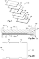
- the multilayer assembly comprising the set 110 of interconnected photovoltaic cells, the encapsulation layers 130 and the protective layers 120, 125 is laminated and called laminated structure 100.
- this laminated structure 100 is supported by a metal frame 140, generally aluminum, which allows the attachment of said laminated structure.
- the metal frame being one of the most expensive elements of the photovoltaic module - after the photovoltaic cells - manufacturers of photovoltaic modules have chosen to remove this metal frame and use clamps 200 to fix the photovoltaic modules 500 to their support, as shown on Figures 2A and 2B .
- one or more clamps 200 are mounted at the edge of the laminated structure 100 so as to exert a transverse force on all the laminated layers.
- each clamp 200 is mounted around a stop 160 of the laminated structure 100 and sandwich said laminated structure.
- clamps 200 allow, by pressing the jaws on the front and rear faces of the laminated structure 100, to maintain said laminated structure in a predetermined position and to fix it on a support or other photovoltaic module, as shown in FIGS. examples of Figures 3A and 3B .
- the applicant proposes to insert at least partially in the laminated structure a spacer for connecting said laminated structure and the collet.
- This photovoltaic assembly is characterized in that it furthermore comprises at least one clamping clamp mounted on the edge of the laminated structure and at least one spacer inserted at least partially in the rolled structure and comprising means intended to make it integral with said clamp.
- This photovoltaic assembly allows a solidarity of the laminated structure with the clamp so that the laminated structure can not detach from said clamp even in the presence of high stresses.
- frameless photovoltaic module will be included in the description as a photovoltaic module that does not include a metal frame intended, in general, to fix said photovoltaic module to a chassis.
- the first face of the set of photovoltaic cells will be called indifferently front face of the set of photovoltaic cells, since it is the face which receives priority light radiation.
- the second face of the set of photovoltaic cells will be referred to indifferently rear face of the set of photovoltaic cells.
- the spacer has a laminated first end within the laminate structure. These embodiments provide a relatively simple insertion of the spacer into the laminate structure.
- the first end of the spacer is inserted into the layer of encapsulating material.
- This first end of the spacer may advantageously be positioned in a plane parallel to the assembly encapsulating the plurality of photovoltaic cells.
- the plane of the laminated structure and therefore the plane of each of the layers of said laminated structure, is the plane in which the largest dimensions of the laminated structure extend, namely the plane which is perpendicular to the dimension containing the thickness of said structure.
- the terms "transverse” or “transversely” mean through the plane of the laminated structure, that is to say according to the dimension containing the thickness of said structure.
- the spacer is a blade. At least part of this blade, for example that inserted into the laminated structure, may include orifices ensuring good encapsulation in the layer of encapsulating material.
- the spacer has a first end traversing transversely at least a portion of the laminated structure.
- the spacer is a rod.
- This rod may be of round, oval, rectangular or polygonal section.
- the spacer may comprise a second end intended to be locked in the collet.
- the first end of the spacer completely traverses the laminated structure in its thickness so that the spacer is able to be clamped between two jaws of the collet. In this way, the collet is inseparable from the laminated structure.
- first end of the rod will also be called the front end of the rod or inner end and the second end of the rod will be called the rear end or outer end.
- the mounting of the photovoltaic module may comprise an installation operation of at least one clamping clamp at the edge of said laminated structure so that the spacer solidarises the laminated structure with the clamping collet.
- the first end of the spacer is inserted into one of the layers of encapsulating material prior to lamination.
- At least part of the multilayer assembly is pierced transversely before lamination and before insertion of the spacer.
- the photovoltaic module comprises an additional step consisting in plugging at least one opening made during the lamination step with parts coated with a poorly adherent polytetrafluoroethylene (PTFE) coating facilitating their removal after lamination.
- PTFE polytetrafluoroethylene
- At least part of the multilayer assembly is pierced transversely after lamination and before insertion of the spacer.
- the second end of the spacer is locked in the collet.
- This photovoltaic module 500 comprises a laminated structure 100, or multilayer assembly, of the type described in the state of the art.
- This laminated structure 100 comprises a set 110 of photovoltaic cells having a front face and a rear face each covered with a layer 130 of a transparent encapsulant material and a protective layer 120, 125.
- the protective layer 120 forming the front face 100a of the laminated structure 100 is generally a protective layer of glass.
- the protective layer 125 forming the rear face 100b of the laminated structure 100 may also be a glass layer, for example when the photovoltaic module is bifacial or a layer of polymer, for example white or opaque, incorporating or not a foil aluminum, especially when the photovoltaic module is monofacial.
- the photovoltaic module 500 can be held by means of clamps 200 as shown in FIG. figure 4 .
- the photovoltaic module 500 and the clamps 200 form a photovoltaic assembly.
- the clamps 200 may be of a conventional type, such as those described in the state of the art, or a type specific to the invention as described below.
- the collets 200 may be separate clamps mounted on the laminated structure 100 and intended to be fixed on a support or a frame.
- the collets 200 may also be an integral part of the support or the frame and allow direct attachment of the laminated structure on said support or frame.
- the photovoltaic module 500 comprises spacers 300 each providing an integral connection between the laminated structure 100 and one of the clamping clamps 200.
- spacers 300 and four collets 200 are shown, it being understood that their number may vary from one to more than four depending on the applications, the support on which the photovoltaic module is to be fixed, the dimensions of the laminated structure and dimensions of the collets.
- each spacer 300 comprises a first section integrated in the laminated structure 100 and a second section secured to the collet 200
- the first section may be an end of the spacer or, on the contrary, the central portion of said spacer and the second section may be, respectively, a second end of the spacer or each of the ends. of said spacer.
- the second section is secured to the collet 200 by various techniques for blocking said second section in the collet or securing said second section on the collet to prevent any moving said second section, and therefore the spacer, relative to the collet.
- the photovoltaic module of the invention may be manufactured according to a manufacturing method, an example of which is shown in FIG. figure 5 .
- This manufacturing method may include, for example, an operation 10 for manufacturing photovoltaic cells and interconnecting these cells in order to obtain an assembly 110 of interconnected photovoltaic cells.
- a protective layer 120, 125 is then deposited on the front face and on the rear face of the set of photovoltaic cells with, interposed between the set of photovoltaic cells and each protective layer, at least one layer. 130 of a transparent encapsulant material.
- Two layers of encapsulating material 130 may be deposited, one on the front face of the set of photovoltaic cells and the other on the rear face of the set of photovoltaic cells, the two layers merging in the step of lamination in a single layer in locations devoid of photovoltaic cells, such as on the outline of the set of photovoltaic cells.
- the various layers are laminated to form a laminated structure 100 and a spacer 300 is inserted at least partially into said laminated structure.
- the various layers 110-130 are laminated in a step 30 and then the spacer 300 is inserted into the laminated structure during a step 40.
- a portion of the spacer 300 is introduced within the layers (step 40) before the set of layers 110-130 is laminated.
- the step 40 for inserting the spacer can take place before the step 30 of lamination of the layers or, conversely, after the step 30 of lamination of the layers, as explained in detail thereafter.
- the collet 200 can be mounted around the edge 160 of the laminated structure 100, that is to say on the edge of said laminated structure, so as to sandwiching all the laminated layers 110-130 and at least a portion of the spacer 300. If several clamps 200 are provided, the mounting of the photovoltaic module 500 is finished when all the collets have been installed on the periphery of the laminated structure 100 and all the struts are secured to said clamps. The photovoltaic module 500 secured to the clamps 200 via the spacers 300 then constitutes a photovoltaic assembly.
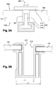
- the spacer 300 may be a plate or a blade 310, for example of polymer or metal, inserted totally or only partially within the laminated layers.
- a first end of the spacer 300 is inserted into the laminated structure 100, the second end of the spacer being locked in the collet 200.
- the blade 310 is inserted entirely in the layer of encapsulating material 130, in the same plane or a plane parallel to the XZ plane containing the layer 110 of the photovoltaic cells so that the first end 313 - or inner end - of the blade 310 is not in contact with the layer 110 of photovoltaic cells.
- the blade 310 may have a thickness of a few hundred microns, for example 600 microns, and be housed in the layer 130 of encapsulating material with a thickness typically between 0.8 and 1.2 mm. It may also have a difference in thickness between the portion 310a intended to be laminated within the layers 110-130 and the portion 310b intended to be outside the laminated structure 100, the latter being up to 10mm for example.
- the blade 310 is inserted into the encapsulating material between the first protective glass layer 120 and the second polymer protective layer 125.
- the blade 310 is inserted into the encapsulating material between the first glass protective layer 120 and the second glass protective layer 125.
- the second end 312 - or outer end - located in the vicinity of the edge 160 of the laminated structure 100 is locked in the collet 200.
- the term "block" any technique to prevent a displacement of the second end relative to the laminated structure.
- the blocking can be obtained by clamping the spacer between two elements or by fixing by means of conventional fastening techniques, such as by gluing, welding or soldering or by mechanical fastening of the type screw / nut or bolt.
- fastening means can be combined, such as a bonding attachment combined with a screw fixing
- the outer end 312 of the spacer 300 may be an integral part of the clamp 200; in this case, the clamp 200 may comprise an element projecting between the jaws 212 and 216 of the clamp 200, which takes the form of a blade 310. The outer end of the spacer is then blocked by its design on the collet.
- the blade 310 forming the spacer 300 may be of rectangular shape or of any other polygonal shape such as a square or diamond shape. It may comprise a flat surface or, on the contrary, rough in order to increase the adhesion with the layer of encapsulating material 130.
- the roughness, on the front face and / or the rear face of the blade, can be for example between 0.8 and 50 ⁇ m.
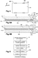
- the blade 310, smooth or rough may also include one or more orifices 340, as shown in FIG. figure 8 , extending in all or part of the thickness of the blade. These orifices may have identical or different diameters that can extend up to about 1 cm.
- the portion 310a of the blade 310 to be laminated within the layers 110-130 contains orifices 340, the portion 310b located outside the laminated structure 100 can be full, without orifices.
- the spacer 300 is a staircase shaped blade whose section has a double L shape.
- the spacer 300 comprises a first blade portion 310 intended to be inserted into the laminated structure 100 a second blade portion 320 for attachment in the chuck 200, for example in an opening 220, and a third blade portion 330 connecting the first and second blade portions.
- the first and second blade portions 310, 320 are in the plane or a plane parallel to the XZ plane containing the layer 110 of the photovoltaic cells, while the third blade portion 330 is in a plane YZ substantially perpendicular to the XZ plane.
- This staircase shape allows the spacer 300 to conform to the shape of the laminated structure 100 so as not to exert excessive stress on the glass protection layer (s) 120, 125 during the operation of lamination.
- each blade 310 is described as providing a mechanical connection between the laminated structure 100 and the collet 200. However, it will be understood that a plurality of blades 310 can connect the laminated structure 100 to one and the same collet 200, the blades 310 being positionable parallel to each other in the XZ plane or the YZ plane.
- the spacer 300 is inserted after lamination, as shown in FIG. figure 5 .
- the spacer 300 is a transverse element 350 of polymer or metal, such as a rod or a rod, of parallelepipedal or cylindrical shape, with a circular, triangular, hexagonal or other section.
- This transverse element 350 hereinafter referred to as the rod 350, is intended to be introduced into an orifice 180 partially or completely traversing the rolled structure 100 in its thickness e.
- the rod 350 transversely crosses only part of the layers of the laminated structure 100. It crosses in particular the rear protective layer 125 and the layer of encapsulating material 130. It does not pass through the protective layer of glass, 120
- the rod 350 extends from the rear jaw 216 of the collet 200 to the layer of encapsulating material 130, the leading end 350a of the rod 350 being housed in said layer of encapsulating material 130 the rear end 350b being locked in the jaw 216 by clamping the collet 200 around the edge 160 of the laminated structure 100 and the rod 350 or fixed in the jaw 216 by one or more of the fastening means such as those described above with reference to Figures 6A-6B .
- FIG. Figure 9A ensures a good mechanical strength of the collet while maintaining a standard glass protection layer.
- the central part of the spacer 300 is inserted into the laminated structure 100, each end of said spacer 300 being locked in the collet 200.
- the rod 350 transversely traverses the whole of the laminated structure 100. In particular, it passes through the rear protective layer 125, made of polymer in the case of the Figure 9B or glass in the case of the Figure 9C as well as the layer of encapsulating material 130 and the protective layer before 120.
- the rod 350 extends between the rear jaw 216 and the front jaw 212 of the collet 200, passing through the laminated structure 100 from one side.
- the method of manufacturing a photovoltaic module then comprises an additional step of plugging the openings made with parts covered with a low adherence coating of the polytetrafluoroethylene type (PTFE) facilitating their removal after lamination.
- PTFE polytetrafluoroethylene type
- the rod 350 is introduced into said structure.
- the collet 200 is then placed and clamped around the edge 160 of the laminated structure so as to lock said shaft 350.
- the shaft 350 may also be attached to the rear jaw 216 and / or the front jaw 212 by one or several of the fixing means described above with reference to Figures 6A-6B .
- the embodiments of the Figures 9B and 9C allow to further improve the mechanical strength of the collet around the laminated structure, said collet can not be detached from the laminated structure.
- the rod 350 is described as providing a mechanical connection between the laminated structure 100 and the collet 200. However, it will be understood that several rods 350 can connect the laminated structure 100 to one and the same collet 200 , the rods 350 being positioned in directions substantially parallel to each other.
- the spacer 300 In the case where an electrical contact with the spacer 300 is possible (directly or via the collet if it is electrically conductive), it is in the form of blade 310 or rod 350, if the spacer 300 is conductive electrical, especially when made of metal, the spacer 300 is positioned at a distance from the photovoltaic cells and their interconnections (in particular metal ribbons) so as not to generate a short circuit between the internal connections of the assembly of photovoltaic cells and said spacer.
- a minimum distance for example of 10 mm in the case of category I materials and a photovoltaic system of 1000 V, must be respected between the positioning of a metal spacer 300 and the set of photovoltaic cells; the distance is at least 2mm if the insulating adhesive material between the front face and the back face can be considered as a glue joint (IEC 61730-1: 2016 standard).
- the photovoltaic module according to the invention comprises various variants, modifications and improvements which will become obvious to those skilled in the art, it being understood that these variants, modifications and improvements are within the scope of the invention.
Abstract
L'invention concerne un ensemble photovoltaïque comprenant un module photovoltaïque (500) sans cadre comportant une structure laminée (100) comportant successivement :- une première couche de protection (120),- un ensemble (130) encapsulant une pluralité de cellules photovoltaïques interconnectées entre elles, et- une deuxième couche de protection (125),- au moins une pince de serrage (200) montée en lisière de la structure laminée (100), et- au moins une entretoise (300) insérée au moins partiellement dans la structure laminée (100) et comportant des moyens destinés à la rendre solidaire de ladite pince de serrage (200).The invention relates to a photovoltaic assembly comprising a frameless photovoltaic module (500) comprising a laminated structure (100) successively comprising: - a first protective layer (120), - an assembly (130) encapsulating a plurality of interconnected photovoltaic cells between they, and- a second protective layer (125), - at least one clamp (200) mounted on the edge of the laminated structure (100), and- at least one spacer (300) inserted at least partially in the structure laminate (100) and comprising means for making it integral with said clamp (200).
Description
La présente invention concerne un module photovoltaïque sans cadre dont la structure est maintenue au moyen d'une ou plusieurs entretoises. L'invention concerne également un procédé de fabrication d'un tel module photovoltaïque.The present invention relates to a frameless photovoltaic module whose structure is maintained by means of one or more spacers. The invention also relates to a method of manufacturing such a photovoltaic module.
L'invention trouve des applications dans le domaine de l'énergie solaire et, en particulier, dans le domaine des modules photovoltaïques.The invention has applications in the field of solar energy and, in particular, in the field of photovoltaic modules.
Dans le domaine de l'énergie solaire, il est connu d'utiliser des modules photovoltaïques pour transformer les rayonnements solaires en énergie électrique. Un module photovoltaïque, appelé aussi panneau photovoltaïque, comprend une pluralité de cellules photovoltaïques de même type de technologie, adaptées pour transformer les rayonnements lumineux provenant du soleil en énergie électrique.In the field of solar energy, it is known to use photovoltaic modules to transform solar radiation into electrical energy. A photovoltaic module, also called photovoltaic panel, comprises a plurality of photovoltaic cells of the same type of technology, adapted to transform the light radiation from the sun into electrical energy.
Dans une cellule photovoltaïque, en particulier une cellule photovoltaïque à base de silicium telle qu'une cellule photovoltaïque à homojonction ou à hétérojonction, les porteurs de charge photogénérés, qui contribuent à la génération du courant électrique dans la cellule photovoltaïque, sont collectés grâce à un réseau d'électrodes déposé sur au moins une des deux faces de la cellule, généralement d'une part sur la face qui reçoit directement le rayonnement lumineux, appelée face avant et d'autre part sur la face arrière. Une cellule photovoltaïque peut être monofaciale ou bifaciale. Dans le cas d'une cellule monofaciale, seule la face avant de la cellule reçoit le rayonnement lumineux ; la face arrière est généralement recouverte d'une couche métallique pleine. Dans le cas d'une cellule bifaciale, la face avant reçoit le rayonnement lumineux direct (en provenance directe de la source lumineuse) et la face arrière reçoit le rayonnement lumineux réfléchi.In a photovoltaic cell, in particular a silicon-based photovoltaic cell such as a homojunction or heterojunction photovoltaic cell, the photogenerated charge carriers, which contribute to the generation of the electric current in the photovoltaic cell, are collected by means of a an electrode array deposited on at least one of the two faces of the cell, generally on the one hand on the face which directly receives the light radiation, called the front face and on the other hand on the rear face. A photovoltaic cell can be monofacial or bifacial. In the case of a monofacial cell, only the front face of the cell receives the light radiation; the back side is usually covered with a solid metal layer. In the case of a bifacial cell, the front face receives the direct light radiation (coming directly from the light source) and the rear face receives the reflected light radiation.
Pour former un module photovoltaïque 500, tel que celui représenté sur les
L'ensemble 110 de cellules photovoltaïques interconnectées est généralement encapsulé entre deux couches de protection :
- une couche de
protection 120 en verre, pour la face avant qui reçoit les rayonnements lumineux, et - une couche de
protection 125, pour la face arrière, en polymère lorsque le module est monofacial ou en verre lorsque le module est bifacial,
- a
protective layer 120 of glass, for the front face which receives the light radiation, and - a
protective layer 125, for the rear face, made of polymer when the module is monofacial or glass when the module is bifacial,
L'ensemble multicouche comportant l'ensemble 110 de cellules photovoltaïques interconnectées, les couches d'encapsulation 130 et les couches de protection 120, 125 est laminé et appelé structure laminée 100. Classiquement, cette structure laminée 100 est supportée par un cadre métallique 140, généralement en aluminium, qui permet la fixation de ladite structure laminée.The multilayer assembly comprising the
Le cadre métallique étant l'un des éléments les plus chers du module photovoltaïque - après les cellules photovoltaïques - des fabricants de modules photovoltaïques ont choisi de supprimer ce cadre métallique et d'utiliser des pinces de serrage 200 pour fixer les modules photovoltaïques 500 à leur support, comme représenté sur les
Des exemples de pinces de serrage sont représentés sur les
- une paroi de
blocage 214 positionnée (lorsque la pince est montée sur la structure) parallèlement à l'arrête 160 de la structure laminée 100, et - des
mors blocage 214, dans des plans sensiblement parallèles aux plans contenant la face avant 100a et la face arrière 100b de la structure laminée 100.
- a
locking wall 214 positioned (when the clamp is mounted on the structure) parallel to thestop 160 of the laminatedstructure 100, and -
jaws locking wall 214, in planes substantially parallel to the planes containing thefront face 100a and therear face 100b of the laminatedstructure 100.
Ces pinces de serrage 200 permettent, par pression des mors sur les faces avant et arrière de la structure laminée 100, de maintenir ladite structure laminée dans une position prédéterminée et de la fixer sur un support ou à un autre module photovoltaïque, comme montré dans les exemples des
Toutefois, lorsqu'une forte contrainte extérieure est appliquée au module photovoltaïque, comme un vent fort ou une couche de neige, il arrive que la structure laminée 100 sorte des pinces de serrage 200, ce qui peut entraîner des dommages dudit module photovoltaïque. Dans le but de remédier à ces problèmes de détachement des modules photovoltaïques 500, des fabricants ont proposé de modifier le serrage des pinces de serrage ou de choisir des matériaux dont l'élasticité ou la rugosité assure une meilleure accroche de la structure laminée au sein de la pince de serrage. Cependant, il s'est avéré que ces solutions ne sont pas suffisantes pour s'affranchir des problèmes de détachement des structures laminées.However, when a strong external constraint is applied to the photovoltaic module, such as a strong wind or a layer of snow, the laminated
Pour répondre au problème évoqué ci-dessus du détachement des structures laminées, le demandeur propose d'insérer au moins partiellement dans la structure laminée une entretoise destinée à relier ladite structure laminée et la pince de serrage.In response to the aforementioned problem of detachment of laminated structures, the applicant proposes to insert at least partially in the laminated structure a spacer for connecting said laminated structure and the collet.
Selon un premier aspect, l'invention concerne un ensemble photovoltaïque comprenant un module photovoltaïque sans cadre comportant une structure laminée comportant successivement :
- une première couche de protection,
- un ensemble encapsulant une pluralité de cellules photovoltaïques interconnectées entre elles, et
- une deuxième couche de protection.
- a first layer of protection,
- an assembly encapsulating a plurality of photovoltaic cells interconnected with each other, and
- a second layer of protection.
Cet ensemble photovoltaïque se caractérise par le fait qu'il comporte en outre au moins une pince de serrage montée en lisière de la structure laminée et au moins une entretoise insérée au moins partiellement dans la structure laminée et comportant des moyens destinés à la rendre solidaire avec ladite pince de serrage.This photovoltaic assembly is characterized in that it furthermore comprises at least one clamping clamp mounted on the edge of the laminated structure and at least one spacer inserted at least partially in the rolled structure and comprising means intended to make it integral with said clamp.
Cet ensemble photovoltaïque permet une solidarisation de la structure laminée avec la pince de serrage de sorte que la structure laminée ne peut se détacher de ladite pince même en présence de fortes contraintes.This photovoltaic assembly allows a solidarity of the laminated structure with the clamp so that the laminated structure can not detach from said clamp even in the presence of high stresses.
L'expression « module photovoltaïque sans cadre » sera comprise, dans la description, comme un module photovoltaïque ne comportant pas de cadre métallique destiné, en général, à fixer ledit module photovoltaïque à un châssis.The expression "frameless photovoltaic module" will be included in the description as a photovoltaic module that does not include a metal frame intended, in general, to fix said photovoltaic module to a chassis.
Dans la suite de la description, la première face de l'ensemble de cellules photovoltaïques sera appelée indifféremment face avant de l'ensemble de cellules photovoltaïques, étant donné que c'est la face qui reçoit en priorité les rayonnements lumineux. La seconde face de l'ensemble de cellules photovoltaïques sera quant à elle appelée indifféremment face arrière de l'ensemble de cellules photovoltaïques.In the remainder of the description, the first face of the set of photovoltaic cells will be called indifferently front face of the set of photovoltaic cells, since it is the face which receives priority light radiation. The second face of the set of photovoltaic cells will be referred to indifferently rear face of the set of photovoltaic cells.
Selon certains modes de réalisation, l'entretoise comporte une première extrémité laminée au sein de la structure laminée. Ces modes de réalisation assurent une insertion relativement simple de l'entretoise au sein de la structure laminée.In some embodiments, the spacer has a laminated first end within the laminate structure. These embodiments provide a relatively simple insertion of the spacer into the laminate structure.
De façon avantageuse, la première extrémité de l'entretoise est insérée dans la couche de matériau encapsulant. Cette première extrémité de l'entretoise peut avantageusement être positionnée suivant un plan parallèle à l'ensemble encapsulant la pluralité de cellules photovoltaïques.Advantageously, the first end of the spacer is inserted into the layer of encapsulating material. This first end of the spacer may advantageously be positioned in a plane parallel to the assembly encapsulating the plurality of photovoltaic cells.
Dans la suite de la description, on considèrera que le plan de la structure laminée, et donc le plan de chacune des couches de ladite structure laminée, est le plan dans lequel s'étendent les plus grandes dimensions de la structure laminée, à savoir le plan qui est perpendiculaire à la dimension contenant l'épaisseur de ladite structure. Les termes « transversal » ou « transversalement » s'entendent à travers le plan de la structure laminée, c'est-à-dire suivant la dimension contenant l'épaisseur de ladite structure.In the remainder of the description, it will be considered that the plane of the laminated structure, and therefore the plane of each of the layers of said laminated structure, is the plane in which the largest dimensions of the laminated structure extend, namely the plane which is perpendicular to the dimension containing the thickness of said structure. The terms "transverse" or "transversely" mean through the plane of the laminated structure, that is to say according to the dimension containing the thickness of said structure.
Selon certains modes de réalisation, l'entretoise est une lame. Une partie au moins de cette lame, par exemple celle insérée dans la structure laminée, peut comporter des orifices assurant une bonne encapsulation dans la couche de matériau encapsulant.In some embodiments, the spacer is a blade. At least part of this blade, for example that inserted into the laminated structure, may include orifices ensuring good encapsulation in the layer of encapsulating material.
Selon certains modes de réalisation, l'entretoise comporte une première extrémité traversant transversalement au moins une partie de la structure laminée. Ces modes de réalisation permettent une bonne solidarisation de la pince de serrage avec la structure laminée.According to some embodiments, the spacer has a first end traversing transversely at least a portion of the laminated structure. These modes embodiment allow a good connection of the clamp with the laminated structure.
Selon certains modes de réalisation, l'entretoise est une tige. Cette tige peut être de section ronde, ovale, rectangulaire ou polygonale.In some embodiments, the spacer is a rod. This rod may be of round, oval, rectangular or polygonal section.
De façon avantageuse, et quel que soit le mode de réalisation, l'entretoise peut comporter une deuxième extrémité destinée à être bloquée dans la pince de serrage.Advantageously, and whatever the embodiment, the spacer may comprise a second end intended to be locked in the collet.
Dans certaines variantes, la première extrémité de l'entretoise traverse totalement la structure laminée dans son épaisseur de sorte que l'entretoise est apte à être pincée entre deux mors de la pince de serrage. De cette façon, la pince de serrage est indissociable de la structure laminée.In some embodiments, the first end of the spacer completely traverses the laminated structure in its thickness so that the spacer is able to be clamped between two jaws of the collet. In this way, the collet is inseparable from the laminated structure.
Dans la suite de la description, la première extrémité de la tige sera appelée également extrémité avant de la tige ou extrémité interne et la seconde extrémité de la tige sera appelée extrémité arrière ou extrémité externe.In the following description, the first end of the rod will also be called the front end of the rod or inner end and the second end of the rod will be called the rear end or outer end.
Selon un deuxième aspect, l'invention concerne un procédé de fabrication de l'ensemble photovoltaïque défini ci-dessus. Ce procédé se caractérise par le fait qu'il comporte une étape de lamination d'un ensemble multicouche comprenant successivement :
- une première couche de protection
- au moins une première couche de matériau encapsulant
- une pluralité de cellules photovoltaïques interconnectées entre elles
- au moins une seconde couche de matériau encapsulant
- une seconde couche de protection
- a first layer of protection
- at least a first layer of encapsulant material
- a plurality of photovoltaic cells interconnected with one another
- at least a second layer of encapsulating material
- a second layer of protection
De façon avantageuse, ce procédé de fabrication comporte les opérations suivantes :
- fabrication de cellules photovoltaïques et raccordement électrique desdites cellules photovoltaïques de sorte à former un ensemble de cellules photovoltaïques interconnectées,
- pose d'au moins une couche de matériau encapsulant sur la première couche de protection,
- pose de l'ensemble de cellules photovoltaïques,
- pose d'au moins une couche de matériau encapsulant sur la seconde face de l'ensemble de cellules photovoltaïques,
- pose d'une seconde couche de protection en regard de la seconde face de l'ensemble de cellules photovoltaïques,
- lamination de l'ensemble des couches pour former une structure laminée, et
- insertion d'au moins une extrémité d'une entretoise dans la structure laminée.
- manufacturing photovoltaic cells and electrically connecting said photovoltaic cells so as to form a set of interconnected photovoltaic cells,
- laying at least one layer of encapsulating material on the first protective layer,
- installation of the set of photovoltaic cells,
- placing at least one layer of material encapsulating on the second face of the set of photovoltaic cells,
- laying a second protective layer opposite the second face of the set of photovoltaic cells,
- laminating all the layers to form a laminated structure, and
- inserting at least one end of a spacer into the laminate structure.
Le montage du module photovoltaïque peut comporter une opération d'installation d'au moins une pince de serrage en lisière de ladite structure laminée de sorte que l'entretoise solidarise la structure laminée avec la pince de serrage.The mounting of the photovoltaic module may comprise an installation operation of at least one clamping clamp at the edge of said laminated structure so that the spacer solidarises the laminated structure with the clamping collet.
Avantageusement, les opérations citées ci-dessus sont réalisées dans l'ordre énoncé, excepté les opérations de lamination de l'ensemble des couches et d'insertion d'une extrémité de l'entretoise qui peuvent être interverties.Advantageously, the operations mentioned above are carried out in the stated order, except for the operations of lamination of all the layers and insertion of one end of the spacer which can be reversed.
Selon certains modes de réalisation, la première extrémité de l'entretoise est insérée dans l'une des couches de matériau encapsulant avant lamination.In some embodiments, the first end of the spacer is inserted into one of the layers of encapsulating material prior to lamination.
Selon d'autres modes de réalisation, une partie au moins de l'ensemble multicouche est percé transversalement avant lamination et avant insertion de l'entretoise.According to other embodiments, at least part of the multilayer assembly is pierced transversely before lamination and before insertion of the spacer.
Selon une variante, le module photovoltaïque comporte une étape supplémentaire consistant à boucher au moins une ouverture réalisée durant l'étape de lamination à l'aide de pièces recouvertes d'un revêtement peu adhérent de type polytétrafluoroéthylène (PTFE) facilitant leur retrait après la lamination.According to one variant, the photovoltaic module comprises an additional step consisting in plugging at least one opening made during the lamination step with parts coated with a poorly adherent polytetrafluoroethylene (PTFE) coating facilitating their removal after lamination. .
Selon d'autres modes de réalisation, une partie au moins de l'ensemble multicouche est percé transversalement après lamination et avant insertion de l'entretoise.According to other embodiments, at least part of the multilayer assembly is pierced transversely after lamination and before insertion of the spacer.
De façon avantageuse, la deuxième extrémité de l'entretoise est bloquée dans la pince de serrage.Advantageously, the second end of the spacer is locked in the collet.
D'autres avantages et caractéristiques de l'invention apparaîtront à la lecture de la description, illustrée par les figures dans lesquelles :
- La
figure 1 , déjà décrite, représente une vue éclatée d'un module photovoltaïque classique ; - Les
figures 2A et 2B , déjà décrites, représentent respectivement une vue en coupe de côté et une vue de dessus d'un module photovoltaïque sans cadre, classique ; - Les
figures 3A et 3B représentent des vues en coupe de modules photovoltaïques selon l'art antérieur ; - La
figure 4 représente une vue de dessus d'un module photovoltaïque selon l'invention ; - La
figure 5 représente un diagramme fonctionnel montrant un exemple de procédé de fabrication du module photovoltaïque selon l'invention ; - Les
figures 6A-6B et7A-7B représentent des vues de côté en coupe de différents modes de réalisation du module photovoltaïque de l'invention ; - La
figure 8 représente une vue de dessus d'un exemple d'entretoise des modes de réalisation desfigures 6A-6B et7A-7B ; - Les
figures 9A,9B et 9C représentent des vues de côté en coupe d'autres modes de réalisation du module photovoltaïque de l'invention.
- The
figure 1 , already described, represents an exploded view of a conventional photovoltaic module; - The
Figures 2A and 2B , already described, respectively represent a sectional side view and a top view of a conventional frameless photovoltaic module; - The
Figures 3A and 3B represent sectional views of photovoltaic modules according to the prior art; - The
figure 4 represents a top view of a photovoltaic module according to the invention; - The
figure 5 represents a functional diagram showing an example of a method of manufacturing the photovoltaic module according to the invention; - The
Figures 6A-6B and7A-7B are cross-sectional side views of different embodiments of the photovoltaic module of the invention; - The
figure 8 is a top view of an exemplary spacer of the embodiments ofFigures 6A-6B and7A-7B ; - The
Figures 9A, 9B and 9C are sectional side views of other embodiments of the photovoltaic module of the invention.
Un exemple de réalisation d'un module photovoltaïque, dans lequel la structure laminée est maintenue par une entretoise, est décrit en détail ci-après, en référence aux dessins annexés. Cet exemple illustre les caractéristiques et avantages de l'invention. Il est toutefois rappelé que l'invention ne se limite pas à cet exemple.An exemplary embodiment of a photovoltaic module, in which the laminated structure is held by a spacer, is described in detail below, with reference to the accompanying drawings. This example illustrates the features and advantages of the invention. However, it is recalled that the invention is not limited to this example.
Sur les figures, les éléments identiques sont repérés par des références identiques. Pour des questions de lisibilité des figures, les échelles de taille entre éléments représentés ne sont pas respectées.In the figures, the identical elements are identified by identical references. For questions of readability of the figures, the size scales between elements represented are not respected.
Un exemple d'un module photovoltaïque selon l'invention est représenté selon une vue de dessus sur la
Le module photovoltaïque 500 peut être maintenu au moyen de pinces de serrage 200 comme représenté sur la
Selon l'invention, le module photovoltaïque 500 comporte des entretoises 300 assurant chacune une liaison solidaire entre la structure laminée 100 et une des pinces de serrage 200. Dans l'exemple de la
Comme décrit plus en détail par la suite, pour assurer une liaison solidaire entre la structure laminée 100 et la pince de serrage 200, chaque entretoise 300 comporte un premier tronçon intégré dans la structure laminée 100 et un deuxième tronçon solidarisé avec la pince de serrage 200. En fonction du mode de réalisation, le premier tronçon peut être une extrémité de l'entretoise ou, au contraire, la partie centrale de ladite entretoise et le deuxième tronçon peuvent être, respectivement, une deuxième extrémité de l'entretoise ou chacune des extrémités de ladite entretoise.As described in more detail below, to ensure a solid connection between the
Le deuxième tronçon est solidarisé avec la pince de serrage 200 par diverses techniques permettant de bloquer ledit deuxième tronçon dans la pince de serrage ou de fixer ledit deuxième tronçon sur la pince de serrage afin d'empêcher tout déplacement dudit deuxième tronçon, et donc de l'entretoise, par rapport à la pince de serrage.The second section is secured to the
Le module photovoltaïque de l'invention peut être fabriqué suivant un procédé de fabrication dont un exemple est représenté sur la
Une fois les différentes couches déposées, celles-ci sont laminées de façon à former une structure laminée 100 et une entretoise 300 est insérée au moins partiellement dans ladite structure laminée. Selon certains modes de réalisation, les différentes couches 110-130 sont laminées dans une étape 30 puis l'entretoise 300 est insérée dans la structure laminée lors d'une étape 40. Selon certains autres modes de réalisation, une partie de l'entretoise 300 est introduite au sein des couches (étape 40) avant que l'ensemble des couches 110-130 ne soit laminé. Autrement dit, en fonction du mode de réalisation choisi, l'étape 40 d'insertion de l'entretoise peut intervenir avant l'étape 30 de lamination des couches ou, au contraire, après l'étape 30 de lamination des couches, comme expliqué en détail par la suite.Once the various layers are deposited, they are laminated to form a
Lorsque l'entretoise 300 est insérée dans la structure laminée 100, la pince de serrage 200 peut être montée autour de l'arête 160 de la structure laminée 100, c'est-à-dire en lisière de ladite structure laminée, de façon à prendre en sandwich l'ensemble des couches laminées 110-130 ainsi qu'une partie au moins de l'entretoise 300. Si plusieurs pinces de serrage 200 sont prévues, le montage du module photovoltaïque 500 est terminé lorsque toutes les pinces de serrage ont été installées sur le pourtour de la structure laminée 100 et que toutes les entretoises sont solidarisées avec lesdites pinces. Le module photovoltaïque 500 solidarisé avec les pinces de serrage 200 via les entretoises 300 constitue alors un ensemble photovoltaïque.When the
Dans les modes de réalisation où l'entretoise 300 est insérée avant lamination, comme par exemple dans les modes de réalisation des
Dans l'exemple de la
Dans les exemples des
Dans une variante, l'extrémité externe 312 de l'entretoise 300 peut faire partie intégrante de la pince 200 ; dans ce cas, la pince 200 peut comporter un élément en saillie entre les mors 212 et 216 de la pince 200, qui prend la forme d'une lame 310. L'extrémité externe de l'entretoise est alors bloquée de par sa conception sur la pince de serrage.In a variant, the
La lame 310 formant l'entretoise 300 peut être de forme rectangulaire ou de toute autre forme polygonale telle qu'une forme carrée ou losangée. Elle peut comporter une surface plane ou, au contraire, rugueuse afin d'augmenter l'adhésion avec la couche de matériau encapsulant 130. La rugosité, sur la face avant et/ou la face arrière de la lame, peut être par exemple comprise entre 0,8 et 50 µm. La lame 310, lisse ou rugueuse, peut également comporter un ou plusieurs orifices 340, comme représenté sur la
Dans les exemples des
Dans la description qui précède, chaque lame 310 est décrite comme assurant une liaison mécanique entre la structure laminée 100 et la pince de serrage 200. On comprendra toutefois que plusieurs lames 310 peuvent relier la structure laminée 100 à une seule et même pince de serrage 200, les lames 310 pouvant être positionnées parallèlement les unes aux autres dans le plan XZ ou le plan YZ.In the foregoing description, each
Dans d'autres modes de réalisation, l'entretoise 300 est insérée après lamination, comme représenté sur la
Dans l'exemple de la
Dans les modes de réalisation des
Afin que la tige 350 puisse traverser totalement la structure laminée 100, ladite structure laminée aura préalablement été percée d'un orifice traversant, d'un diamètre supérieur ou égal au diamètre de la tige 350. Le percement de la structure laminée peut être réalisé avant ou après l'opération de lamination référencée 30 sur la
Dans la description qui précède, la tige 350 est décrite comme assurant une liaison mécanique entre la structure laminée 100 et la pince de serrage 200. On comprendra toutefois que plusieurs tiges 350 peuvent relier la structure laminée 100 à une seule et même pince de serrage 200, les tiges 350 étant positionnées suivant des directions sensiblement parallèles les unes aux autres.In the above description, the
Dans le cas où un contact électrique avec l'entretoise 300 est possible (directement ou via la pince de serrage si elle est conductrice électrique), qu'elle soit sous forme de lame 310 ou de tige 350, si l'entretoise 300 est conductrice électrique, en particulier lorsqu'elle est en métal, l'entretoise 300 est positionnée à distance des cellules photovoltaïques et de leurs interconnexions (notamment rubans métalliques) de sorte à ne pas générer de court-circuit entre les connexions internes de l'ensemble de cellules photovoltaïques et ladite entretoise. Une distance minimale, par exemple de 10mm dans le cas de matériaux de catégorie I et d'un système photovoltaïque de 1000 V, doit être respectée entre le positionnement d'une l'entretoise 300 métallique et l'ensemble de cellules photovoltaïques ; la distance est de minimum 2mm si le matériau adhésif isolant entre la face avant et la face arrière peut être considéré comme un joint collé (norme IEC 61730-1:2016).In the case where an electrical contact with the
Bien que décrit à travers un certain nombre d'exemples, variantes et modes de réalisation, le module photovoltaïque selon l'invention comprend divers variantes, modifications et perfectionnements qui apparaîtront de façon évidente à l'homme du métier, étant entendu que ces variantes, modifications et perfectionnements font partie de la portée de l'invention.Although described through a certain number of examples, variants and embodiments, the photovoltaic module according to the invention comprises various variants, modifications and improvements which will become obvious to those skilled in the art, it being understood that these variants, modifications and improvements are within the scope of the invention.
Claims (15)
Applications Claiming Priority (1)
| Application Number | Priority Date | Filing Date | Title |
|---|---|---|---|
| FR1853215A FR3080242B1 (en) | 2018-04-12 | 2018-04-12 | FRAMELESS PHOTOVOLTAIC MODULE AND METHOD FOR MANUFACTURING SUCH MODULE |
Publications (2)
| Publication Number | Publication Date |
|---|---|
| EP3553941A1 true EP3553941A1 (en) | 2019-10-16 |
| EP3553941B1 EP3553941B1 (en) | 2021-05-26 |
Family
ID=63014698
Family Applications (1)
| Application Number | Title | Priority Date | Filing Date |
|---|---|---|---|
| EP19168707.8A Active EP3553941B1 (en) | 2018-04-12 | 2019-04-11 | Photovoltaic module without frame and method for manufacturing such a module |
Country Status (2)
| Country | Link |
|---|---|
| EP (1) | EP3553941B1 (en) |
| FR (1) | FR3080242B1 (en) |
Citations (3)
| Publication number | Priority date | Publication date | Assignee | Title |
|---|---|---|---|---|
| EP2267793A1 (en) * | 2009-06-22 | 2010-12-29 | L & T Partners | Attachment assembly for a panel |
| US20160365827A1 (en) * | 2015-06-09 | 2016-12-15 | Nextracker Inc. | Frameless solar module mounting |
| US20170163210A1 (en) * | 2015-12-08 | 2017-06-08 | Lee Gorny | Photovoltaic module |
-
2018
- 2018-04-12 FR FR1853215A patent/FR3080242B1/en not_active Expired - Fee Related
-
2019
- 2019-04-11 EP EP19168707.8A patent/EP3553941B1/en active Active
Patent Citations (3)
| Publication number | Priority date | Publication date | Assignee | Title |
|---|---|---|---|---|
| EP2267793A1 (en) * | 2009-06-22 | 2010-12-29 | L & T Partners | Attachment assembly for a panel |
| US20160365827A1 (en) * | 2015-06-09 | 2016-12-15 | Nextracker Inc. | Frameless solar module mounting |
| US20170163210A1 (en) * | 2015-12-08 | 2017-06-08 | Lee Gorny | Photovoltaic module |
Also Published As
| Publication number | Publication date |
|---|---|
| FR3080242B1 (en) | 2022-01-14 |
| FR3080242A1 (en) | 2019-10-18 |
| EP3553941B1 (en) | 2021-05-26 |
Similar Documents
| Publication | Publication Date | Title |
|---|---|---|
| EP3118920B1 (en) | Self-supporting thin film battery and method for producing such a battery | |
| EP0184877B1 (en) | Matrix of electroluminescent elements and production method thereof | |
| EP0230336B1 (en) | Optoelectronic device for surface mounting | |
| EP2452369B1 (en) | Method for manufacturing photovoltaic cells with multiple junctions and multiple electrodes | |
| EP2510553B1 (en) | Photovoltaic cell, method for assembling plurality of cells, and assembly of a plurality of photovoltaic cells | |
| EP1586122B1 (en) | Photovoltaic module comprising external connector pins | |
| FR3043840A1 (en) | LIGHT PHOTOVOLTAIC MODULE COMPRISING A FRONT GLASS OR POLYMER LAYER AND AN ALVEOLAR REAR LAYER | |
| EP4002491B1 (en) | Improved light and flexible photovoltaic module | |
| EP3378102B1 (en) | Lightweight photovoltaic module including a front layer made from glass or polymer and a rear layer comprising raised portions | |
| EP3553941B1 (en) | Photovoltaic module without frame and method for manufacturing such a module | |
| EP3884526B1 (en) | Flexible satellite solar generator and its manufacturing method | |
| FR3052595A1 (en) | METHOD FOR MANUFACTURING A PHOTOVOLTAIC MODULE | |
| EP2737541B1 (en) | Photovoltaic module with simplified connection | |
| FR3081614A1 (en) | PHOTOVOLTAIC MODULE COMPRISING ONE OR MORE BYPASS DIODES ON THE BACK SIDE OF A MODULE PHOTOVOLTAIC CELL | |
| WO2012043702A1 (en) | Solar-cell module | |
| FR3074963A1 (en) | PHOTOVOLTAIC MODULE COMPRISING PHOTOVOLTAIC CELLS INTERCONNECTED BY INTERCONNECTION ELEMENTS | |
| FR3024591A1 (en) | METHOD FOR MANUFACTURING A PHOTOVOLTAIC PANEL | |
| FR3060852A1 (en) | PHOTOVOLTAIC DEVICE AND METHOD OF MANUFACTURING THE SAME | |
| FR3004002A1 (en) | PROCESS FOR ADVANCED ASSEMBLY OF CONCENTRATED PHOTOVOLTAIC CELL | |
| EP3244456B1 (en) | Photovoltaic module including photovoltaic cells arranged with different orientations and associated photovoltaic system | |
| EP3691120A1 (en) | Three-dimensional solar cell and photovoltaic solar module | |
| EP3721482A1 (en) | Production of a concentrating sub-module using photovoltaic assembly methods | |
| WO2022129278A1 (en) | Interconnector for strings of solar cells that are intended to form a photovoltaic module | |
| EP4032131B1 (en) | Photovoltaic module comprising an electrically conductive connection element | |
| FR3116651A1 (en) | Method for manufacturing a light and flexible photovoltaic module incorporating thermal protection |
Legal Events
| Date | Code | Title | Description |
|---|---|---|---|
| PUAI | Public reference made under article 153(3) epc to a published international application that has entered the european phase |
Free format text: ORIGINAL CODE: 0009012 |
|
| STAA | Information on the status of an ep patent application or granted ep patent |
Free format text: STATUS: REQUEST FOR EXAMINATION WAS MADE |
|
| 17P | Request for examination filed |
Effective date: 20190411 |
|
| AK | Designated contracting states |
Kind code of ref document: A1 Designated state(s): AL AT BE BG CH CY CZ DE DK EE ES FI FR GB GR HR HU IE IS IT LI LT LU LV MC MK MT NL NO PL PT RO RS SE SI SK SM TR |
|
| AX | Request for extension of the european patent |
Extension state: BA ME |
|
| RBV | Designated contracting states (corrected) |
Designated state(s): AL AT BE BG CH CY CZ DE DK EE ES FI FR GB GR HR HU IE IS IT LI LT LU LV MC MK MT NL NO PL PT RO RS SE SI SK SM TR |
|
| GRAP | Despatch of communication of intention to grant a patent |
Free format text: ORIGINAL CODE: EPIDOSNIGR1 |
|
| STAA | Information on the status of an ep patent application or granted ep patent |
Free format text: STATUS: GRANT OF PATENT IS INTENDED |
|
| INTG | Intention to grant announced |
Effective date: 20201218 |
|
| GRAS | Grant fee paid |
Free format text: ORIGINAL CODE: EPIDOSNIGR3 |
|
| GRAA | (expected) grant |
Free format text: ORIGINAL CODE: 0009210 |
|
| STAA | Information on the status of an ep patent application or granted ep patent |
Free format text: STATUS: THE PATENT HAS BEEN GRANTED |
|
| AK | Designated contracting states |
Kind code of ref document: B1 Designated state(s): AL AT BE BG CH CY CZ DE DK EE ES FI FR GB GR HR HU IE IS IT LI LT LU LV MC MK MT NL NO PL PT RO RS SE SI SK SM TR |
|
| REG | Reference to a national code |
Ref country code: GB Ref legal event code: FG4D Free format text: NOT ENGLISH |
|
| REG | Reference to a national code |
Ref country code: CH Ref legal event code: EP |
|
| REG | Reference to a national code |
Ref country code: DE Ref legal event code: R096 Ref document number: 602019004808 Country of ref document: DE |
|
| REG | Reference to a national code |
Ref country code: AT Ref legal event code: REF Ref document number: 1397253 Country of ref document: AT Kind code of ref document: T Effective date: 20210615 |
|
| REG | Reference to a national code |
Ref country code: IE Ref legal event code: FG4D Free format text: LANGUAGE OF EP DOCUMENT: FRENCH |
|
| REG | Reference to a national code |
Ref country code: LT Ref legal event code: MG9D |
|
| REG | Reference to a national code |
Ref country code: AT Ref legal event code: MK05 Ref document number: 1397253 Country of ref document: AT Kind code of ref document: T Effective date: 20210526 |
|
| PG25 | Lapsed in a contracting state [announced via postgrant information from national office to epo] |
Ref country code: BG Free format text: LAPSE BECAUSE OF FAILURE TO SUBMIT A TRANSLATION OF THE DESCRIPTION OR TO PAY THE FEE WITHIN THE PRESCRIBED TIME-LIMIT Effective date: 20210826 Ref country code: AT Free format text: LAPSE BECAUSE OF FAILURE TO SUBMIT A TRANSLATION OF THE DESCRIPTION OR TO PAY THE FEE WITHIN THE PRESCRIBED TIME-LIMIT Effective date: 20210526 Ref country code: LT Free format text: LAPSE BECAUSE OF FAILURE TO SUBMIT A TRANSLATION OF THE DESCRIPTION OR TO PAY THE FEE WITHIN THE PRESCRIBED TIME-LIMIT Effective date: 20210526 Ref country code: HR Free format text: LAPSE BECAUSE OF FAILURE TO SUBMIT A TRANSLATION OF THE DESCRIPTION OR TO PAY THE FEE WITHIN THE PRESCRIBED TIME-LIMIT Effective date: 20210526 Ref country code: FI Free format text: LAPSE BECAUSE OF FAILURE TO SUBMIT A TRANSLATION OF THE DESCRIPTION OR TO PAY THE FEE WITHIN THE PRESCRIBED TIME-LIMIT Effective date: 20210526 |
|
| REG | Reference to a national code |
Ref country code: NL Ref legal event code: MP Effective date: 20210526 |
|
| PG25 | Lapsed in a contracting state [announced via postgrant information from national office to epo] |
Ref country code: GR Free format text: LAPSE BECAUSE OF FAILURE TO SUBMIT A TRANSLATION OF THE DESCRIPTION OR TO PAY THE FEE WITHIN THE PRESCRIBED TIME-LIMIT Effective date: 20210827 Ref country code: IS Free format text: LAPSE BECAUSE OF FAILURE TO SUBMIT A TRANSLATION OF THE DESCRIPTION OR TO PAY THE FEE WITHIN THE PRESCRIBED TIME-LIMIT Effective date: 20210926 Ref country code: LV Free format text: LAPSE BECAUSE OF FAILURE TO SUBMIT A TRANSLATION OF THE DESCRIPTION OR TO PAY THE FEE WITHIN THE PRESCRIBED TIME-LIMIT Effective date: 20210526 Ref country code: NO Free format text: LAPSE BECAUSE OF FAILURE TO SUBMIT A TRANSLATION OF THE DESCRIPTION OR TO PAY THE FEE WITHIN THE PRESCRIBED TIME-LIMIT Effective date: 20210826 Ref country code: PL Free format text: LAPSE BECAUSE OF FAILURE TO SUBMIT A TRANSLATION OF THE DESCRIPTION OR TO PAY THE FEE WITHIN THE PRESCRIBED TIME-LIMIT Effective date: 20210526 Ref country code: RS Free format text: LAPSE BECAUSE OF FAILURE TO SUBMIT A TRANSLATION OF THE DESCRIPTION OR TO PAY THE FEE WITHIN THE PRESCRIBED TIME-LIMIT Effective date: 20210526 Ref country code: PT Free format text: LAPSE BECAUSE OF FAILURE TO SUBMIT A TRANSLATION OF THE DESCRIPTION OR TO PAY THE FEE WITHIN THE PRESCRIBED TIME-LIMIT Effective date: 20210927 Ref country code: SE Free format text: LAPSE BECAUSE OF FAILURE TO SUBMIT A TRANSLATION OF THE DESCRIPTION OR TO PAY THE FEE WITHIN THE PRESCRIBED TIME-LIMIT Effective date: 20210526 |
|
| PG25 | Lapsed in a contracting state [announced via postgrant information from national office to epo] |
Ref country code: NL Free format text: LAPSE BECAUSE OF FAILURE TO SUBMIT A TRANSLATION OF THE DESCRIPTION OR TO PAY THE FEE WITHIN THE PRESCRIBED TIME-LIMIT Effective date: 20210526 |
|
| PG25 | Lapsed in a contracting state [announced via postgrant information from national office to epo] |
Ref country code: RO Free format text: LAPSE BECAUSE OF FAILURE TO SUBMIT A TRANSLATION OF THE DESCRIPTION OR TO PAY THE FEE WITHIN THE PRESCRIBED TIME-LIMIT Effective date: 20210526 Ref country code: SM Free format text: LAPSE BECAUSE OF FAILURE TO SUBMIT A TRANSLATION OF THE DESCRIPTION OR TO PAY THE FEE WITHIN THE PRESCRIBED TIME-LIMIT Effective date: 20210526 Ref country code: CZ Free format text: LAPSE BECAUSE OF FAILURE TO SUBMIT A TRANSLATION OF THE DESCRIPTION OR TO PAY THE FEE WITHIN THE PRESCRIBED TIME-LIMIT Effective date: 20210526 Ref country code: DK Free format text: LAPSE BECAUSE OF FAILURE TO SUBMIT A TRANSLATION OF THE DESCRIPTION OR TO PAY THE FEE WITHIN THE PRESCRIBED TIME-LIMIT Effective date: 20210526 Ref country code: EE Free format text: LAPSE BECAUSE OF FAILURE TO SUBMIT A TRANSLATION OF THE DESCRIPTION OR TO PAY THE FEE WITHIN THE PRESCRIBED TIME-LIMIT Effective date: 20210526 Ref country code: ES Free format text: LAPSE BECAUSE OF FAILURE TO SUBMIT A TRANSLATION OF THE DESCRIPTION OR TO PAY THE FEE WITHIN THE PRESCRIBED TIME-LIMIT Effective date: 20210526 Ref country code: SK Free format text: LAPSE BECAUSE OF FAILURE TO SUBMIT A TRANSLATION OF THE DESCRIPTION OR TO PAY THE FEE WITHIN THE PRESCRIBED TIME-LIMIT Effective date: 20210526 |
|
| REG | Reference to a national code |
Ref country code: DE Ref legal event code: R097 Ref document number: 602019004808 Country of ref document: DE |
|
| PLBE | No opposition filed within time limit |
Free format text: ORIGINAL CODE: 0009261 |
|
| STAA | Information on the status of an ep patent application or granted ep patent |
Free format text: STATUS: NO OPPOSITION FILED WITHIN TIME LIMIT |
|
| 26N | No opposition filed |
Effective date: 20220301 |
|
| PG25 | Lapsed in a contracting state [announced via postgrant information from national office to epo] |
Ref country code: IS Free format text: LAPSE BECAUSE OF FAILURE TO SUBMIT A TRANSLATION OF THE DESCRIPTION OR TO PAY THE FEE WITHIN THE PRESCRIBED TIME-LIMIT Effective date: 20210926 Ref country code: AL Free format text: LAPSE BECAUSE OF FAILURE TO SUBMIT A TRANSLATION OF THE DESCRIPTION OR TO PAY THE FEE WITHIN THE PRESCRIBED TIME-LIMIT Effective date: 20210526 |
|
| PG25 | Lapsed in a contracting state [announced via postgrant information from national office to epo] |
Ref country code: IT Free format text: LAPSE BECAUSE OF FAILURE TO SUBMIT A TRANSLATION OF THE DESCRIPTION OR TO PAY THE FEE WITHIN THE PRESCRIBED TIME-LIMIT Effective date: 20210526 |
|
| REG | Reference to a national code |
Ref country code: DE Ref legal event code: R119 Ref document number: 602019004808 Country of ref document: DE |
|
| REG | Reference to a national code |
Ref country code: CH Ref legal event code: PL |
|
| REG | Reference to a national code |
Ref country code: BE Ref legal event code: MM Effective date: 20220430 |
|
| PG25 | Lapsed in a contracting state [announced via postgrant information from national office to epo] |
Ref country code: MC Free format text: LAPSE BECAUSE OF FAILURE TO SUBMIT A TRANSLATION OF THE DESCRIPTION OR TO PAY THE FEE WITHIN THE PRESCRIBED TIME-LIMIT Effective date: 20210526 Ref country code: LU Free format text: LAPSE BECAUSE OF NON-PAYMENT OF DUE FEES Effective date: 20220411 Ref country code: LI Free format text: LAPSE BECAUSE OF NON-PAYMENT OF DUE FEES Effective date: 20220430 Ref country code: DE Free format text: LAPSE BECAUSE OF NON-PAYMENT OF DUE FEES Effective date: 20221103 Ref country code: CH Free format text: LAPSE BECAUSE OF NON-PAYMENT OF DUE FEES Effective date: 20220430 |
|
| PG25 | Lapsed in a contracting state [announced via postgrant information from national office to epo] |
Ref country code: BE Free format text: LAPSE BECAUSE OF NON-PAYMENT OF DUE FEES Effective date: 20220430 |
|
| PG25 | Lapsed in a contracting state [announced via postgrant information from national office to epo] |
Ref country code: IE Free format text: LAPSE BECAUSE OF NON-PAYMENT OF DUE FEES Effective date: 20220411 |
|
| PGFP | Annual fee paid to national office [announced via postgrant information from national office to epo] |
Ref country code: FR Payment date: 20230424 Year of fee payment: 5 |
|
| GBPC | Gb: european patent ceased through non-payment of renewal fee |
Effective date: 20230411 |
|
| PG25 | Lapsed in a contracting state [announced via postgrant information from national office to epo] |
Ref country code: GB Free format text: LAPSE BECAUSE OF NON-PAYMENT OF DUE FEES Effective date: 20230411 |
|
| PG25 | Lapsed in a contracting state [announced via postgrant information from national office to epo] |
Ref country code: GB Free format text: LAPSE BECAUSE OF NON-PAYMENT OF DUE FEES Effective date: 20230411 |
|
| PG25 | Lapsed in a contracting state [announced via postgrant information from national office to epo] |
Ref country code: HU Free format text: LAPSE BECAUSE OF FAILURE TO SUBMIT A TRANSLATION OF THE DESCRIPTION OR TO PAY THE FEE WITHIN THE PRESCRIBED TIME-LIMIT; INVALID AB INITIO Effective date: 20190411 |