EP3553885B1 - Antenne réseau et appareil de réseau - Google Patents
Antenne réseau et appareil de réseau Download PDFInfo
- Publication number
- EP3553885B1 EP3553885B1 EP16925510.6A EP16925510A EP3553885B1 EP 3553885 B1 EP3553885 B1 EP 3553885B1 EP 16925510 A EP16925510 A EP 16925510A EP 3553885 B1 EP3553885 B1 EP 3553885B1
- Authority
- EP
- European Patent Office
- Prior art keywords
- strips
- strip
- fixed
- movable
- ports
- Prior art date
- Legal status (The legal status is an assumption and is not a legal conclusion. Google has not performed a legal analysis and makes no representation as to the accuracy of the status listed.)
- Active
Links
Images


Classifications
-
- H—ELECTRICITY
- H01—ELECTRIC ELEMENTS
- H01P—WAVEGUIDES; RESONATORS, LINES, OR OTHER DEVICES OF THE WAVEGUIDE TYPE
- H01P1/00—Auxiliary devices
- H01P1/10—Auxiliary devices for switching or interrupting
- H01P1/12—Auxiliary devices for switching or interrupting by mechanical chopper
- H01P1/127—Strip line switches
-
- H—ELECTRICITY
- H01—ELECTRIC ELEMENTS
- H01Q—ANTENNAS, i.e. RADIO AERIALS
- H01Q1/00—Details of, or arrangements associated with, antennas
- H01Q1/12—Supports; Mounting means
- H01Q1/22—Supports; Mounting means by structural association with other equipment or articles
- H01Q1/24—Supports; Mounting means by structural association with other equipment or articles with receiving set
- H01Q1/241—Supports; Mounting means by structural association with other equipment or articles with receiving set used in mobile communications, e.g. GSM
- H01Q1/246—Supports; Mounting means by structural association with other equipment or articles with receiving set used in mobile communications, e.g. GSM specially adapted for base stations
-
- H—ELECTRICITY
- H01—ELECTRIC ELEMENTS
- H01Q—ANTENNAS, i.e. RADIO AERIALS
- H01Q1/00—Details of, or arrangements associated with, antennas
- H01Q1/36—Structural form of radiating elements, e.g. cone, spiral, umbrella; Particular materials used therewith
- H01Q1/38—Structural form of radiating elements, e.g. cone, spiral, umbrella; Particular materials used therewith formed by a conductive layer on an insulating support
-
- H—ELECTRICITY
- H01—ELECTRIC ELEMENTS
- H01Q—ANTENNAS, i.e. RADIO AERIALS
- H01Q21/00—Antenna arrays or systems
- H01Q21/0006—Particular feeding systems
-
- H—ELECTRICITY
- H01—ELECTRIC ELEMENTS
- H01Q—ANTENNAS, i.e. RADIO AERIALS
- H01Q25/00—Antennas or antenna systems providing at least two radiating patterns
- H01Q25/002—Antennas or antenna systems providing at least two radiating patterns providing at least two patterns of different beamwidth; Variable beamwidth antennas
-
- H—ELECTRICITY
- H01—ELECTRIC ELEMENTS
- H01Q—ANTENNAS, i.e. RADIO AERIALS
- H01Q3/00—Arrangements for changing or varying the orientation or the shape of the directional pattern of the waves radiated from an antenna or antenna system
- H01Q3/24—Arrangements for changing or varying the orientation or the shape of the directional pattern of the waves radiated from an antenna or antenna system varying the orientation by switching energy from one active radiating element to another, e.g. for beam switching
- H01Q3/247—Arrangements for changing or varying the orientation or the shape of the directional pattern of the waves radiated from an antenna or antenna system varying the orientation by switching energy from one active radiating element to another, e.g. for beam switching by switching different parts of a primary active element
-
- H—ELECTRICITY
- H01—ELECTRIC ELEMENTS
- H01Q—ANTENNAS, i.e. RADIO AERIALS
- H01Q3/00—Arrangements for changing or varying the orientation or the shape of the directional pattern of the waves radiated from an antenna or antenna system
- H01Q3/26—Arrangements for changing or varying the orientation or the shape of the directional pattern of the waves radiated from an antenna or antenna system varying the relative phase or relative amplitude of energisation between two or more active radiating elements; varying the distribution of energy across a radiating aperture
- H01Q3/30—Arrangements for changing or varying the orientation or the shape of the directional pattern of the waves radiated from an antenna or antenna system varying the relative phase or relative amplitude of energisation between two or more active radiating elements; varying the distribution of energy across a radiating aperture varying the relative phase between the radiating elements of an array
- H01Q3/34—Arrangements for changing or varying the orientation or the shape of the directional pattern of the waves radiated from an antenna or antenna system varying the relative phase or relative amplitude of energisation between two or more active radiating elements; varying the distribution of energy across a radiating aperture varying the relative phase between the radiating elements of an array by electrical means
- H01Q3/36—Arrangements for changing or varying the orientation or the shape of the directional pattern of the waves radiated from an antenna or antenna system varying the relative phase or relative amplitude of energisation between two or more active radiating elements; varying the distribution of energy across a radiating aperture varying the relative phase between the radiating elements of an array by electrical means with variable phase-shifters
- H01Q3/38—Arrangements for changing or varying the orientation or the shape of the directional pattern of the waves radiated from an antenna or antenna system varying the relative phase or relative amplitude of energisation between two or more active radiating elements; varying the distribution of energy across a radiating aperture varying the relative phase between the radiating elements of an array by electrical means with variable phase-shifters the phase-shifters being digital
-
- H—ELECTRICITY
- H04—ELECTRIC COMMUNICATION TECHNIQUE
- H04W—WIRELESS COMMUNICATION NETWORKS
- H04W16/00—Network planning, e.g. coverage or traffic planning tools; Network deployment, e.g. resource partitioning or cells structures
- H04W16/24—Cell structures
- H04W16/28—Cell structures using beam steering
Definitions
- This application relates to the field of antenna technologies, and in particular, to an array antenna and a network device.
- the antenna is required to provide, depending on a different application scenario, a different operating state that meets a requirement of the application scenario, and the base station antenna is also required to be miniaturized. Therefore, to meet both a requirement of an appropriate antenna size and indicator requirements in a plurality of application scenarios, an array design innovation is required for the base station antenna in diversified application scenarios.
- a distance between a reflective plate side of an antenna and a radiating element is adjusted by moving a position of the reflective plate side, to change a surrounding environment of the radiating element.
- current distribution on the radiating element, a bottom surface of the reflective plate, and the reflective plate side is changed, so as to change a beam width of a radiation directivity pattern of the antenna.
- adjusting the reflective plate side slightly affects the current distribution, and therefore, the beam width changes in a relatively small range.
- US 2004/157645 A1 discloses operation of an array antenna.
- the array antenna has configurable beamwidth and is operable in any of multiple operating modes associated with respective beamwidths.
- US 2 609 503 A relates to high frequency antennae as particularly used with television or other high frequency systems employing selective directive radiation.
- US 2009/277762 A1 discloses a micromachine switch for switching an electrical connection between signal electrodes in accordance with control signals.
- the micromachine switch comprises a substrate; a rotating body provided on the substrate, which is rotatable on the substrate; a movable electrode provided on the rotating body and signal electrodes, which are electrically dis/connected to the movable electrode according to movements of the rotating body.
- CH 331 382 A discloses a high-frequency switch for a tape conductor.
- GB 966 549 A discloses operation of an array antenna.
- the array antenna is operable in multiple operating modes associated with respective beam orientations.
- This application provides an array antenna, to flexibly change a beam width of a radiation directivity pattern of an antenna.
- the present invention is defined by an antenna according to independent claims 1 and 3.
- the array antenna in this application includes: the n radiating elements; the power splitter or the phase shifter, including the n output ends and the m input ends, where the n output ends are respectively connected to the n radiating elements, and the any one of the m input ends is connected to the at least one of the n output ends; and the switching switch, including the m first ports, the K second ports, and the switch element, where the m first ports are respectively connected to the m input ends, the K second ports are configured to couple the input signal, and the switch element is configured to switch the connection relationship between the m first ports and the K second ports, so as to selectively output the input signal to the at least one first port.
- the switching switch is configured to control transmission or interruption of a signal that is output to the n radiating elements, and set the quantity of radiating elements in an operating state, so as to flexibly change the beam width of the radiation directivity pattern of the antenna.
- the switching switch for setting the radiating element to an operating or non-operating state has a simple structure, and causes a relatively small introduced insertion loss, gains of the antenna are relatively high.
- This application provides an array antenna that can flexibly change a beam width of a radiation directivity pattern of an antenna.
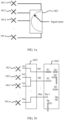
- FIG. 1a is a schematic diagram of an array antenna according to Embodiment 1 of this application. As shown in FIG. 1a , the array antenna includes:
- the switching switch 1021 may control transmission or interruption of a signal that is output by the feeding network to the n radiating elements, and set a quantity of radiating elements in an operating state, that is, set different operating modes, so as to flexibly change a beam width of a radiation directivity pattern of an antenna.
- the n radiating elements may be single-polarized radiating elements, or may be dual-polarized radiating elements, and a balun corresponding to each polarization direction of a radiating element has signal excitation provided by a corresponding feeding network.
- n is a positive integer, and a specific value of n may be set by persons skilled in the art according to an actual situation. To flexibly change the beam width of the radiation directivity pattern of the antenna, the value of n may be greater than or equal to 2.
- FIG. 1b is a specific schematic structural diagram of an array antenna according to Embodiment 1 of this application. As shown in FIG. 1b , the array antenna includes:
- the switching switch 1021 includes m first ports, K second ports, and a switch element, where the m first ports are respectively connected to the m input ends; the K second ports are configured to couple an input signal; and the switch element is configured to switch a connection relationship between the m first ports and the K second ports, so as to selectively output the input signal to at least one first port.
- the switch element includes p fixed strips (P1, P2, ..., Pp-1, and Pp) and q movable strips (Q1, Q2, Q3, ..., and Qq), where ends of m fixed strips in the p fixed strips act as the m first ports and are respectively connected to the m input ends, and the q movable strips are selectively connected to the p fixed strips.
- the p fixed strips include K signal input lines configured to input signals, and ends of K fixed strips act as the K second ports.
- a specific quantity of signal input lines may be set by persons skilled in the art according to experience and an actual situation, for example, one signal input line or a plurality of signal input lines may be set. In this application, one or more fixed strips may be set as signal input lines.
- the q movable strips are selectively connected to the p fixed strips specifically means that the q movable strips may be connected to different fixed strips based on a to-be-connected radiating element by changing a position of at least one movable strip.
- the q movable strips in the switch element may be selectively connected to the p fixed strips, to control transmission or interruption of the signal that is output by the feeding network to the n radiating elements, and set the quantity of radiating elements in an operating state, thereby flexibly changing the beam width of the radiation directivity pattern of the antenna.
- the foregoing structure may be used to flexibly change a horizontal beam width of the antenna; if the n radiating elements are sequentially arranged in a vertical direction, the foregoing structure may be used to flexibly change a vertical beam width of the antenna; and if the n radiating elements are sequentially arranged in another direction, the foregoing structure may be used to flexibly change a beam width of the antenna in the another direction.
- the switch element further includes a pull rod, and the pull rod is connected to at least one of the q movable strips, so that a position of a movable strip connected to the pull rod can be changed by using the pull rod, to selectively connect the movable strip to a fixed strip.
- the pull rod may be electrically controlled, for example, by using a motor, or may be manually controlled.
- each movable strip may be connected to one pull rod, or another connection manner may be used, provided that the q movable strips can be controlled to selectively connect to the p fixed strips.
- a specific connection manner is not specifically limited.
- the q movable strips and the p fixed strips may be metal strips with a relatively small thickness, or copper foil strips of a printed circuit board (Printed Circuit Board, PCB). This is not specifically limited.
- the q movable strips may be selectively connected to the p fixed strips in a plurality of manners, for example, in an electrical manner or capacitive coupling manner.
- At least two operating modes may be set by using the switching switch.
- only two operating modes (Embodiment 2 and Embodiment 3) and three operating modes (Embodiment 4 and Embodiment 5) set by using the switching switch are used as examples for description.
- An array antenna includes two radiating elements (a radiating element 1011 and a radiating element 1012) and a feeding network.
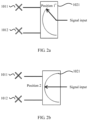
- the feeding network includes a switching switch 1021, and two operating modes set by using the switching switch are shown in FIG. 2a and FIG. 2b .
- FIG. 2a is a schematic diagram of using a switching switch to control one radiating element to operate in Embodiment 2. As shown in FIG. 2a , when the switching switch is switched to a position 1, a signal that is output through the feeding network to the radiating element 1011 is transmitted, and a signal that is output to the radiating element 1012 is interrupted. In this case, the radiating element 1011 is in an operating state, and the radiating element 1012 is not in an operating state.
- FIG. 2b is a schematic diagram of using a switching switch to control two radiating elements to operate in Embodiment 2. As shown in FIG. 2b , when the switching switch is switched to a position 2, signals that are output through the feeding network to the radiating element 1011 and the radiating element 1012 are transmitted. In this case, both the radiating element 1011 and the radiating element 1012 are in an operating state.
- a quantity of radiating elements in an operating state can be set by changing the switching switch to control transmission or interruption of a signal that is output by the feeding network to the radiating elements, thereby changing a beam width of an antenna.
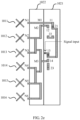
- FIG. 2c is a specific schematic structural diagram of an array antenna according to Embodiment 2 of this application. As shown in FIG. 2c , the array antenna includes:
- the switching switch 1021 includes four fixed strips (11, 12, 13, and 14, as shown in FIG. 2d ) and q movable strips (21, 22, and 23, as shown in FIG. 2d ). Three of the four fixed strips are respectively connected to the three input ends, that is, 11 is connected to M1, 12 is connected to M2, and 14 is connected to M3; and the fixed strip 13 is a signal input line.
- a fixed strip connected to a movable strip may be changed by changing a position of the movable strip, so as to control transmission or interruption of a signal that is output by the feeding network to the six radiating elements, and set the quantity of radiating elements in an operating state, that is, set different operating modes as shown in FIG. 2e and FIG. 2f , thereby flexibly changing a beam width of a radiation directivity pattern of an antenna.
- FIG. 2e is a schematic diagram of using a switching switch to control one radiating element to operate in Embodiment 2.
- the movable strip 21 is connected to the fixed strip 11 and the fixed strip 13 in a direct electrical connection or capacitive coupling manner to implement signal connection.
- the radiating element 1011 is in a signal-transmittable state with the feeding network, and therefore the radiating element 1011 is in an operating state.
- the beam width of the directivity pattern of the antenna is widest, and the antenna is suitable for a high-rise building coverage scenario.
- FIG. 2f is a schematic diagram of using a switching switch to control six radiating elements to operate in Embodiment 2.
- the movable strip 22 is connected to the fixed strip 11 and the fixed strip 12 in a direct electrical connection or capacitive coupling manner to implement signal connection
- the movable strip 23 is connected to the fixed strip 13 and the fixed strip 14 in a direct electrical connection or capacitive coupling manner to implement signal connection.
- the radiating element 1011, the radiating element 1012, the radiating element 1013, the radiating element 1014, the radiating element 1015, and the radiating element 1016 are all in a signal-transmittable state with the feeding network, and therefore the radiating element 1011, the radiating element 1012, the radiating element 1013, the radiating element 1014, the radiating element 1015, and the radiating element 1016 are all in an operating state.
- the radiating element 1011, the radiating element 1012, the radiating element 1013, the radiating element 1014, the radiating element 1015, and the radiating element 1016 are all in an operating state.
- the beam width of the directivity pattern of the antenna is narrowest, and the antenna is suitable for a street macro-coverage scenario.
- An array antenna includes two radiating elements (a radiating element 1011 and a radiating element 1012) and a feeding network.
- the feeding network includes a switching switch 1021 and a phase shifter 1022, and two operating modes set by using the switching switch are shown in FIG. 3a and FIG. 3b .
- a direction of an antenna beam may be changed by changing a phase of the phase shifter.
- the phase shifter may change the phase by changing a dielectric constant of a signal channel, or may change the phase by changing a physical length of a signal channel, or may change the phase in another implementation.
- FIG. 3a is a schematic diagram of using a switching switch to control one radiating element to operate in Embodiment 3. As shown in FIG. 3a , when the switching switch is switched to a position 1, a signal that is output through the feeding network to the radiating element 1011 is transmitted, and a signal that is output to the radiating element 1012 is interrupted. In this case, the radiating element 1011 is in an operating state, and the radiating element 1012 is not in an operating state.
- FIG. 3b is a schematic diagram of using a switching switch to control two radiating elements to operate in Embodiment 3. As shown in FIG. 3b , when the switching switch is switched to a position 2, signals that are output through the feeding network to the radiating element 1011 and the radiating element 1012 are transmitted. In this case, both the radiating element 1011 and the radiating element 1012 are in an operating state.
- a quantity of radiating elements in an operating state can be set by changing the switching switch to control transmission or interruption of a signal that is output by the feeding network to the radiating elements, thereby changing a beam width of an antenna.
- An array antenna includes three radiating elements (a radiating element 1011, a radiating element 1012, and a radiating element 1013) and a feeding network.
- the feeding network includes a switching switch 1021, and three operating modes set by using the switching switch are shown in FIG. 4a to FIG. 4c .
- FIG. 4a is a schematic diagram of using a switching switch to control one radiating element to operate in Embodiment 4.
- the switching switch when the switching switch is switched to a position 1, a signal that is output through the feeding network to the radiating element 1011 is transmitted, and signals that are output to the radiating element 1012 and the radiating element 1013 are interrupted.
- the radiating element 1011 is in an operating state, and the radiating element 1012 and the radiating element 1013 are not in an operating state.
- FIG. 4b is a schematic diagram of using a switching switch to control two radiating elements to operate in Embodiment 4.
- the switching switch when the switching switch is switched to a position 2, signals that are output through the feeding network to the radiating element 1011 and the radiating element 1012 are transmitted, and a signal that is output to the radiating element 1013 is interrupted.
- the radiating element 1011 and the radiating element 1012 are in an operating state, and the radiating element 1013 is not in an operating state.
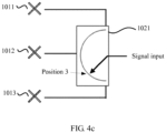
- FIG. 4c is a schematic diagram of using a switching switch to control three radiating elements to operate in Embodiment 4. As shown in FIG. 4c , when the switching switch is switched to a position 3, signals that are output through the feeding network to the radiating element 1011, the radiating element 1012, and the radiating element 1013 are all transmitted. In this case, the radiating element 1011, the radiating element 1012, and the radiating element 1013 are all in an operating state.
- a quantity of radiating elements in an operating state can be set by changing the switching switch to control transmission or interruption of a signal that is output by the feeding network to the radiating elements, thereby changing a beam width of an antenna.
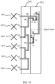
- FIG. 4d is a specific schematic structural diagram of an array antenna according to Embodiment 4 of this application. As shown in FIG. 4d , the array antenna includes:
- the switching switch 1021 includes five fixed strips (11, 12, 13, 14, and 15, as shown in FIG. 4e ) and q movable strips (21, 22, 23, 24, and 25, as shown in FIG. 4e ).
- Four of the five fixed strips are respectively connected to the four input ends, that is, 11 is connected to M1, 12 is connected to M2, 13 is connected to M3, and 14 is connected to M4.
- a fixed strip connected to a movable strip may be changed by changing a position of the movable strip, so as to control transmission or interruption of a signal that is output by the feeding network to the six radiating elements, and set the quantity of radiating elements in an operating state, thereby flexibly changing a beam width of a radiation directivity pattern of the antenna.
- FIG. 4f to FIG. 4h are schematic diagrams of controlling radiating elements to be in different operating states by using a switching switch.
- FIG. 4f is a schematic diagram of using a switching switch to control one radiating element to operate in Embodiment 4.
- the movable strip 23 is connected to the fixed strip 11 and the fixed strip 15 in a direct electrical connection or capacitive coupling manner to implement signal connection.
- the radiating element 1011 is in a signal-transmittable state with the feeding network, and therefore the radiating element 1011 is in an operating state.
- the beam width of the directivity pattern of the antenna is widest, and the antenna is suitable for a high-rise building coverage scenario.
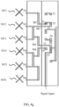
- FIG. 4g is a schematic diagram of using a switching switch to control three radiating elements to operate in Embodiment 4.
- the movable strip 22 is connected to the fixed strip 11 and the fixed strip 12 in a direct electrical connection or capacitive coupling manner to implement signal connection
- the movable strip 25 is connected to the fixed strip 13 and the fixed strip 15 in a direct electrical connection or capacitive coupling manner to implement signal connection.
- the radiating element 1011, the radiating element 1012, and the radiating element 1013 are in a signal-transmittable state with the feeding network, and therefore the radiating element 1011, the radiating element 1012, and the radiating element 1013 are in an operating state.
- the beam width of the directivity pattern of the antenna is medium, and the antenna is suitable for a mid- and low-rise building coverage scenario.
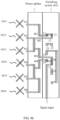
- FIG. 4h is a schematic diagram of using a switching switch to control six radiating elements to operate in Embodiment 4.
- the movable strip 21 is connected to the fixed strip 11 and the fixed strip 12 in a direct electrical connection or capacitive coupling manner to implement signal connection
- the movable strip 24 is connected to the fixed strip 13, the fixed strip 14, and the fixed strip 15 in a direct electrical connection or capacitive coupling manner to implement signal connection.
- the radiating element 1011, the radiating element 1012, the radiating element 1013, the radiating element 1014, the radiating element 1015, and the radiating element 1016 are all in a signal-transmittable state with the feeding network, and therefore the radiating element 1011, the radiating element 1012, the radiating element 1013, the radiating element 1014, the radiating element 1015, and the radiating element 1016 are all in an operating state.
- the radiating element 1011, the radiating element 1012, the radiating element 1013, the radiating element 1014, the radiating element 1015, and the radiating element 1016 are all in an operating state.
- the beam width of the directivity pattern of the antenna is narrowest, and the antenna is suitable for a street macro-coverage scenario.
- An array antenna includes three radiating elements (a radiating element 1011, a radiating element 1012, and a radiating element 1013) and a feeding network.
- the feeding network includes a switching switch 1021 and a phase shifter 1022, and two operating modes set by using the switching switch are shown in FIG. 5a and FIG. 5b .
- a direction of an antenna beam may be changed by changing a phase of the phase shifter.
- the phase shifter may change the phase by changing a dielectric constant of a signal channel, or may change the phase by changing a physical length of a signal channel, or may change the phase in another implementation.
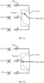
- FIG. 5a is a schematic diagram of using a switching switch to control one radiating element to operate in Embodiment 5.
- the switching switch when the switching switch is switched to a position 1, a signal that is output through the feeding network to the radiating element 1011 is transmitted, and signals that are output to the radiating element 1012 and the radiating element 1013 are interrupted.
- the radiating element 1011 is in an operating state, and the radiating element 1012 and the radiating element 1013 are not in an operating state.
- FIG. 5b is a schematic diagram of using a switching switch to control two radiating elements to operate in Embodiment 5.
- the switching switch when the switching switch is switched to a position 2, signals that are output through the feeding network to the radiating element 1011 and the radiating element 1012 are transmitted, and a signal that is output to the radiating element 1013 is interrupted.
- the radiating element 1011 and the radiating element 1012 are in an operating state, and the radiating element 1013 is not in an operating state.
- FIG. 5c is a schematic diagram of using a switching switch to control three radiating elements to operate in Embodiment 5. As shown in FIG. 5c , when the switching switch is switched to a position 3, signals that are output through the feeding network to the radiating element 1011, the radiating element 1012, and the radiating element 1013 are all transmitted. In this case, the radiating element 1011, the radiating element 1012, and the radiating element 1013 are all in an operating state.
- a quantity of radiating elements in an operating state can be set by changing the switching switch to control transmission or interruption of a signal that is output by the feeding network to the radiating elements, thereby changing a beam width of an antenna.
- This application further provides a network device, including the array antenna described in the foregoing embodiments.
Landscapes
- Engineering & Computer Science (AREA)
- Computer Networks & Wireless Communication (AREA)
- Signal Processing (AREA)
- Variable-Direction Aerials And Aerial Arrays (AREA)
Claims (8)
- Antenne, comprenant :n éléments rayonnants (1011, 1012, 1013..., 101n) ;un diviseur de puissance (1022) ou un déphaseur (1022), comprenant n extrémités de sortie (N1, N2, N3, ..., et Nn) et m extrémités d'entrée (M1, M2, ..., et Mm), les n extrémités de sortie (N1, N2, N3, ..., et Nn) étant respectivement connectées aux n éléments rayonnants (1011, 1012, 1013, ..., 101n), et l'une quelconque des m extrémités d'entrée (M1, M2, ..., et Mm) étant connectée à au moins l'une des n extrémités de sortie (N1, N2, N3, ..., et Nn) ; etun commutateur de commutation (1021), comprenant m premiers ports, K seconds ports, et un élément de commutation, les m premiers ports étant respectivement connectés aux m extrémités d'entrée (M1, M2, ..., et Mm) ;les K seconds ports étant configurés pour coupler un signal d'entrée ; et l'élément de commutation étant configuré pour commuter une relation de connexion entre les m premiers ports et les K seconds ports, de manière à délivrer en sortie sélectivement le signal d'entrée à au moins un premier port,n et m étant des entiers supérieurs à 1, et K étant un entier supérieur ou égal à 1, l'élément de commutation comprenant p bandes fixes (P1, P2, ..., et Pp) et q bandes mobiles (Q1, Q2, Q3, ..., et Qq) ; etdes extrémités de m bandes fixes dans les p bandes fixes agissant comme les m premiers ports, les q bandes mobiles étant connectées sélectivement aux p bandes fixes, et m ≤ p,des extrémités de K bandes fixes dans les p bandes fixes agissant comme les K seconds ports, et K ≤ p,l'élément de commutation comprenant en outre au moins une tige de traction connectée à au moins une des q bandes mobiles, de sorte qu'une position d'une bande mobile connectée à l'au moins une tige de traction peut être modifiée en utilisant la tige de traction, pour connecter sélectivement la bande mobile à une bande fixe,les p bandes fixes comprenant une première bande fixe jusqu'à une quatrième bande fixe (11, 12, 13, 14), la première bande fixe, la deuxième bande fixe et la quatrième bande fixe étant respectivement connectées à la première extrémité d'entrée, à la deuxième extrémité d'entrée et à la troisième extrémité d'entrée, et une extrémité de la troisième bande fixe agissant comme l'un des K seconds ports ; et les q bandes mobiles comprenant une première bande mobile jusqu'à une troisième bande mobile (21, 22, 23) ; etles q bandes mobiles étant sélectivement connectées aux p bandes fixes avec spécifiquement :la première bande mobile (21) étant connectée à la première bande fixe (11) et à la troisième bande fixe (13) dans un premier mode de fonctionnement défini par le commutateur de commutation ; etla deuxième bande mobile (22) étant connectée à la première bande fixe (11) et à la deuxième bande fixe (12),et la troisième bande mobile (23) étant connectée à la troisième bande fixe (13) et à la quatrième bande fixe (14) dans un deuxième mode de fonctionnement défini par le commutateur de commutation.
- Antenne selon la revendication 1, les n extrémités de sortie (N1, N2, N3, ..., et Nn) comprenant une première extrémité de sortie jusqu'à une sixième extrémité de sortie, et les m extrémités d'entrée comprenant la première extrémité d'entrée jusqu'à la troisième extrémité d'entrée,la première extrémité d'entrée étant connectée à la première extrémité de sortie ;la deuxième extrémité d'entrée étant connectée à la deuxième extrémité de sortie, à la troisième extrémité de sortie, à la quatrième extrémité de sortie, à la cinquième extrémité de sortie et à la sixième extrémité de sortie ; etla troisième extrémité d'entrée étant connectée à la deuxième extrémité de sortie, à la troisième extrémité de sortie, à la quatrième extrémité de sortie, à la cinquième extrémité de sortie et à la sixième extrémité de sortie.
- Antenne, comprenant :n éléments rayonnants (1011, 1012, 1013... 101n) ;un diviseur de puissance (1022) ou un déphaseur (1022), comprenant n extrémités de sortie (N1, N2, N3, ..., et Nn) et m extrémités d'entrée (M1, M2, ..., et Mm), les n extrémités de sortie (N1, N2, N3, ..., et Nn) étant respectivement connectées aux n éléments rayonnants (1011, 1012, 1013... 101n), et l'une quelconque des m extrémités d'entrée (M1, M2, ..., et Mm) étant connectée à au moins l'une des n extrémités de sortie (N1, N2, N3, ..., et Nn), etun commutateur de commutation (1021), comprenant m premiers ports, K seconds ports, et un élément de commutation, les m premiers ports étant respectivement connectés aux m extrémités d'entrée (M1, M2, ..., et Mm) ; les K seconds ports étant configurés pour coupler un signal d'entrée ; et l'élément de commutation étant configuré pour commuter une relation de connexion entre les m premiers ports et les K seconds ports, de manière à délivrer en sortie sélectivement le signal d'entrée à au moins un premier port,n et m étant des entiers supérieurs à 1, et K étant un entier supérieur ou égal à 1, l'élément de commutation comprenant p bandes fixes (P1, P2, ..., et Pp) et q bandes mobiles (Q1, Q2, Q3, ..., et Qq) ; et des extrémités de m bandes fixes dans les p bandes fixes agissant comme les m premiers ports, les q bandes mobiles étant sélectivement connectées aux p bandes fixes, et m ≤ p,des extrémités de K bandes fixes dans les p bandes fixes agissant comme les K seconds ports, et K ≤ p, l'élément de commutation comprenant en outre au moins une tige de traction connectée à au moins une des q bandes mobiles, de sorte qu'une position d'une bande mobile connectée à l'au moins une tige de traction peut être modifiée en utilisant la tige de traction, pour connecter sélectivement la bande mobile à une bande fixe,les p bandes fixes comprenant une première bande fixe jusqu'à une cinquième bande fixe (11, 12, 13, 14, 15), la première bande fixe jusqu'à la quatrième bande fixe étant respectivement connectées à une première extrémité d'entrée jusqu'à une quatrième extrémité d'entrée, et une extrémité de la cinquième bande fixe agissant comme l'un des K seconds ports ; et les q bandes mobiles comprenant une première bande mobile jusqu'à une cinquième bande mobile (21, 22, 23, 24, 25) ; etles q bandes mobiles étant sélectivement connectées aux p bandes fixes avec spécifiquement :la troisième bande mobile (23) étant connectée à la première bande fixe (11) et à la cinquième bande fixe (15) dans un troisième mode de fonctionnement défini par le commutateur de commutation ; etla deuxième bande mobile (22) étant connectée à la première bande fixe (11) et à la deuxième bande fixe (12),et la cinquième bande mobile (25) étant connectée à la troisième bande fixe (13) et à la cinquième bande fixe (15) dans un quatrième mode de fonctionnement défini par le commutateur de commutation ; etla première bande mobile (21) étant connectée à la première bande fixe (11) et à la deuxième bande fixe (12), et la quatrième bande mobile (24) étant connectée à la troisième bande fixe (13), à la quatrième bande fixe (14) et à la cinquième bande fixe (15) dans un cinquième mode de fonctionnement défini par le commutateur de commutation.
- Antenne selon la revendication 3, les n extrémités de sortie comprenant une première extrémité de sortie jusqu' à une sixième extrémité de sortie, et les m extrémités d'entrée comprenant la première extrémité d'entrée jusqu'à la quatrième extrémité d'entrée, la première extrémité d'entrée étant connectée à la première extrémité de sortie ;la deuxième extrémité d'entrée étant connectée à la deuxième extrémité de sortie et à la troisième extrémité de sortie ;la troisième extrémité d'entrée étant connectée à la deuxième extrémité de sortie et à la troisième extrémité de sortie ; etla quatrième extrémité d'entrée étant connectée à la quatrième extrémité de sortie, à la cinquième extrémité de sortie et à la sixième extrémité de sortie.
- Antenne selon l'une quelconque des revendications 1 à 4, les q bandes mobiles étant sélectivement connectées aux p bandes fixes de manière électrique ou par couplage capacitif.
- Antenne selon l'une quelconque des revendications 1 à 5, les p bandes fixes et les q bandes mobiles étant des bandes métalliques ou des bandes de feuilles de cuivre d'une carte de circuit imprimé, PCB.
- Antenne selon l'une quelconque des revendications 1 à 6, les n éléments rayonnants étant agencés séquentiellement dans une direction horizontale ou dans une direction verticale.
- Dispositif de réseau, comprenant l'antenne selon l'une quelconque des revendications 1 à 7.
Priority Applications (1)
| Application Number | Priority Date | Filing Date | Title |
|---|---|---|---|
| EP23152821.7A EP4220860A3 (fr) | 2016-12-29 | 2016-12-29 | Antenne et dispositif de réseau |
Applications Claiming Priority (1)
| Application Number | Priority Date | Filing Date | Title |
|---|---|---|---|
| PCT/CN2016/113156 WO2018119928A1 (fr) | 2016-12-29 | 2016-12-29 | Antenne réseau et appareil de réseau |
Related Child Applications (2)
| Application Number | Title | Priority Date | Filing Date |
|---|---|---|---|
| EP23152821.7A Division EP4220860A3 (fr) | 2016-12-29 | 2016-12-29 | Antenne et dispositif de réseau |
| EP23152821.7A Division-Into EP4220860A3 (fr) | 2016-12-29 | 2016-12-29 | Antenne et dispositif de réseau |
Publications (3)
| Publication Number | Publication Date |
|---|---|
| EP3553885A1 EP3553885A1 (fr) | 2019-10-16 |
| EP3553885A4 EP3553885A4 (fr) | 2019-11-27 |
| EP3553885B1 true EP3553885B1 (fr) | 2023-03-01 |
Family
ID=62707751
Family Applications (2)
| Application Number | Title | Priority Date | Filing Date |
|---|---|---|---|
| EP16925510.6A Active EP3553885B1 (fr) | 2016-12-29 | 2016-12-29 | Antenne réseau et appareil de réseau |
| EP23152821.7A Pending EP4220860A3 (fr) | 2016-12-29 | 2016-12-29 | Antenne et dispositif de réseau |
Family Applications After (1)
| Application Number | Title | Priority Date | Filing Date |
|---|---|---|---|
| EP23152821.7A Pending EP4220860A3 (fr) | 2016-12-29 | 2016-12-29 | Antenne et dispositif de réseau |
Country Status (5)
| Country | Link |
|---|---|
| US (1) | US10573958B2 (fr) |
| EP (2) | EP3553885B1 (fr) |
| CN (2) | CN110140256B (fr) |
| BR (1) | BR112019013370B1 (fr) |
| WO (1) | WO2018119928A1 (fr) |
Families Citing this family (12)
| Publication number | Priority date | Publication date | Assignee | Title |
|---|---|---|---|---|
| EP3531505B1 (fr) * | 2016-12-05 | 2020-10-07 | Huawei Technologies Co., Ltd. | Appareil et procédé de suivi de faisceaux, et système d'antennes |
| CN110768026B (zh) | 2018-07-26 | 2021-03-05 | 上海华为技术有限公司 | 一种基站天线和基站设备 |
| CN109346842B (zh) * | 2018-08-27 | 2020-07-28 | 京信通信技术(广州)有限公司 | 波宽可调的天线 |
| JP7372460B2 (ja) * | 2019-09-18 | 2023-10-31 | ホアウェイ・テクノロジーズ・カンパニー・リミテッド | 受動素子を備えたスマートアンテナによるビームダイバーシティ |
| CN113660003B (zh) * | 2020-04-29 | 2022-07-29 | 华为技术有限公司 | 一种耦合/功分装置、rru和系统 |
| CN111641049A (zh) * | 2020-05-20 | 2020-09-08 | 广州程星通信科技有限公司 | 一种相控阵切换波束控制方法、系统、装置及存储介质 |
| CN112397884B (zh) * | 2020-10-22 | 2023-07-07 | 重庆品胜科技有限公司 | 一种平面天线 |
| CN112564731B (zh) * | 2020-12-03 | 2022-03-25 | 维沃移动通信有限公司 | 信号处理电路、方法和电子设备 |
| CN113422180A (zh) * | 2021-07-01 | 2021-09-21 | 江苏亨鑫科技有限公司 | 一种多模式移相装置及大规模阵列天线 |
| CN115863971A (zh) * | 2022-12-29 | 2023-03-28 | 东莞市云通通讯科技有限公司 | 矩阵赋用天线 |
| CN116345152A (zh) * | 2023-04-28 | 2023-06-27 | 广东天诺通讯科技有限公司 | 可实现宽窄波束变换的天线 |
| CN116742340A (zh) * | 2023-07-27 | 2023-09-12 | 中国联合网络通信集团有限公司 | 一种天线 |
Citations (1)
| Publication number | Priority date | Publication date | Assignee | Title |
|---|---|---|---|---|
| GB966549A (en) * | 1961-01-17 | 1964-08-12 | Servo Corp Of America | Distributor for use in navigation systems |
Family Cites Families (37)
| Publication number | Priority date | Publication date | Assignee | Title |
|---|---|---|---|---|
| US2609503A (en) * | 1952-04-11 | 1952-09-02 | Marvin P Middlemark | Selective direction television and high-frequency antenna system |
| CH331382A (de) * | 1954-02-08 | 1958-07-15 | Standard Telephon & Radio Ag | Hochfrequenzschalter in einer Bandleitung |
| JP2557401B2 (ja) * | 1987-07-31 | 1996-11-27 | 日本電気株式会社 | 平面アレイアンテナ |
| DE19636850A1 (de) * | 1996-09-11 | 1998-03-12 | Daimler Benz Aerospace Ag | Phasengesteuerte Antenne |
| US5995062A (en) * | 1998-02-19 | 1999-11-30 | Harris Corporation | Phased array antenna |
| JP2000049524A (ja) * | 1998-07-31 | 2000-02-18 | Nec Corp | アレイアンテナ |
| JP3481481B2 (ja) * | 1998-12-24 | 2003-12-22 | 日本電気株式会社 | フェーズドアレイアンテナおよびその製造方法 |
| CN1145239C (zh) * | 2000-03-27 | 2004-04-07 | 信息产业部电信科学技术研究院 | 一种改进智能天线阵列覆盖范围的方法 |
| FR2817661A1 (fr) * | 2000-12-05 | 2002-06-07 | Thomson Multimedia Sa | Dispositif pour la reception et/ou l'emission de signaux multifaisceaux |
| US6388631B1 (en) * | 2001-03-19 | 2002-05-14 | Hrl Laboratories Llc | Reconfigurable interleaved phased array antenna |
| US6750810B2 (en) * | 2001-12-18 | 2004-06-15 | Hitachi, Ltd. | Monopulse radar system |
| US6965349B2 (en) * | 2002-02-06 | 2005-11-15 | Hrl Laboratories, Llc | Phased array antenna |
| KR100653439B1 (ko) * | 2002-12-28 | 2006-12-01 | 주식회사 케이엠더블유 | 안테나 방사빔의 고속 스위핑을 이용한 무선통신 방법 및장치 |
| US20040157645A1 (en) * | 2003-02-12 | 2004-08-12 | Smith Adrian David | System and method of operation an array antenna in a distributed wireless communication network |
| IL155221A0 (en) * | 2003-04-03 | 2003-11-23 | Wavextend Ltd | Phased array antenna for indoor application |
| US7321339B2 (en) * | 2005-01-14 | 2008-01-22 | Farrokh Mohamadi | Phase shifters for beamforming applications |
| JP3944606B2 (ja) * | 2005-01-31 | 2007-07-11 | オプテックス株式会社 | フェーズドアレーアンテナ装置 |
| JP4531607B2 (ja) * | 2005-03-30 | 2010-08-25 | 富士通株式会社 | キャリブレーション装置 |
| KR100971096B1 (ko) * | 2005-06-09 | 2010-07-20 | 맥도널드, 디트윌러 앤드 어소시에이츠 엘티디. | 경량의 공간-피딩된 능동 위상 어레이 안테나 시스템 |
| US8022794B2 (en) * | 2006-04-28 | 2011-09-20 | Panasonic Corporation | Micromachine switch, filter circuit, duplexer circuit, and communication device |
| WO2010147987A1 (fr) * | 2009-06-15 | 2010-12-23 | Agc Automotive Amerlcas R&D, Inc. | Système et procédé à antenne à réception simultanée |
| US8648268B2 (en) * | 2010-01-04 | 2014-02-11 | Fluke Corporation | Electro-mechanical microwave switch |
| US9231292B2 (en) * | 2010-02-01 | 2016-01-05 | Georgia Tech Research Corporation | Multi-antenna signaling scheme for low-powered or passive radio communications |
| CN102142888B (zh) * | 2011-01-31 | 2014-04-02 | 华为技术有限公司 | 一种微波设备和微波传输方法 |
| CN103004020B (zh) * | 2011-07-26 | 2016-12-28 | 华为技术有限公司 | 天线系统和天线重构方法 |
| CN102646874B (zh) * | 2012-04-20 | 2015-04-08 | 电子科技大学 | 一种基于单刀多掷开关的四维天线阵 |
| CN102856667A (zh) * | 2012-09-06 | 2013-01-02 | 上海瀚讯无线技术有限公司 | 一种多波束天线系统 |
| CN203277596U (zh) * | 2013-05-24 | 2013-11-06 | 华为技术有限公司 | 移相器 |
| CN203813033U (zh) * | 2013-12-23 | 2014-09-03 | 华为技术有限公司 | 一种多频阵列天线 |
| CN104135300B (zh) * | 2014-08-07 | 2017-04-12 | 上海无线电设备研究所 | Ku波段多通道切换接收装置及切换接收方法 |
| CN104243005B (zh) * | 2014-09-03 | 2017-12-29 | 华为技术有限公司 | 天线功能扩展装置、设备和对天线进行功能扩展的方法 |
| US10218068B1 (en) * | 2015-10-29 | 2019-02-26 | National Technology & Engineering Solutions Of Sandia, Llc | In-situ active impedance characterization of scanned array antennas |
| WO2017145257A1 (fr) * | 2016-02-23 | 2017-08-31 | 三菱電機株式会社 | Dispositif d'antenne réseau et son procédé d'étalonnage |
| JP6352963B2 (ja) * | 2016-03-09 | 2018-07-04 | 株式会社東芝 | アンテナ装置及びアレイアンテナ装置 |
| US9929886B2 (en) * | 2016-06-06 | 2018-03-27 | Intel Corporation | Phased array antenna cell with adaptive quad polarization |
| CN106099367B (zh) * | 2016-08-29 | 2019-05-14 | Oppo广东移动通信有限公司 | 天线装置及移动终端 |
| CN106207461A (zh) * | 2016-08-29 | 2016-12-07 | 苏州市吴通天线有限公司 | 一种5g毫米波共形多波束天线系统 |
-
2016
- 2016-12-29 CN CN201680091936.7A patent/CN110140256B/zh active Active
- 2016-12-29 EP EP16925510.6A patent/EP3553885B1/fr active Active
- 2016-12-29 WO PCT/CN2016/113156 patent/WO2018119928A1/fr not_active Ceased
- 2016-12-29 BR BR112019013370-4A patent/BR112019013370B1/pt active IP Right Grant
- 2016-12-29 CN CN202011558797.9A patent/CN112821073B/zh active Active
- 2016-12-29 EP EP23152821.7A patent/EP4220860A3/fr active Pending
-
2019
- 2019-06-27 US US16/455,734 patent/US10573958B2/en active Active
Patent Citations (1)
| Publication number | Priority date | Publication date | Assignee | Title |
|---|---|---|---|---|
| GB966549A (en) * | 1961-01-17 | 1964-08-12 | Servo Corp Of America | Distributor for use in navigation systems |
Also Published As
| Publication number | Publication date |
|---|---|
| CN112821073A (zh) | 2021-05-18 |
| CN112821073B (zh) | 2024-04-26 |
| EP4220860A2 (fr) | 2023-08-02 |
| EP3553885A4 (fr) | 2019-11-27 |
| BR112019013370A2 (pt) | 2019-12-31 |
| BR112019013370B1 (pt) | 2022-11-22 |
| EP3553885A1 (fr) | 2019-10-16 |
| CN110140256A (zh) | 2019-08-16 |
| US10573958B2 (en) | 2020-02-25 |
| CN110140256B (zh) | 2021-01-05 |
| EP4220860A3 (fr) | 2023-11-01 |
| US20190319343A1 (en) | 2019-10-17 |
| WO2018119928A1 (fr) | 2018-07-05 |
Similar Documents
| Publication | Publication Date | Title |
|---|---|---|
| EP3553885B1 (fr) | Antenne réseau et appareil de réseau | |
| US11552385B2 (en) | Feed network of base station antenna, base station antenna, and base station | |
| US9419833B2 (en) | Phase control method, array antenna, and system | |
| TWI713517B (zh) | 天線系統 | |
| US7397425B2 (en) | Electronically steerable sector antenna | |
| EP2984708B1 (fr) | Configuration d'antenne améliorée | |
| KR20010040061A (ko) | L자형 실내 안테나 | |
| JP2005210521A (ja) | アンテナ装置 | |
| CN207852927U (zh) | 3×3Butler矩阵馈电网络及天线 | |
| KR101988382B1 (ko) | 안테나 장치 및 그를 구비하는 전자 기기 | |
| EP3163933B1 (fr) | Réseau de formation de faisceau et antenne de station de base | |
| CN107431269A (zh) | 用于移动通信系统的小型天线设备 | |
| US20060114165A1 (en) | Antenna Assembly | |
| CN103916153B (zh) | 一种有源一体化天线微站 | |
| JP6100075B2 (ja) | アレイアンテナおよび無線通信装置 | |
| CN102842748A (zh) | 有源式天线及电子装置 | |
| WO2024239698A1 (fr) | Déphaseur et antenne | |
| CN113745853B (zh) | 一种天线阵列及无线通信设备 | |
| JP2005109700A (ja) | 無線lanシステムによる屋内移動体の位置検出方法および装置 | |
| WO2026078730A1 (fr) | Système et procédé de communication basée sur une surface réfléchissante intelligente | |
| CN119009452A (zh) | 一种天线 | |
| CN104143692A (zh) | 多天线阵列和基站 | |
| WO2024169336A1 (fr) | Réseau d'alimentation et dispositif d'antenne | |
| GB2425658A (en) | Phase shifting arrangement | |
| Han et al. | Radial fed SP8T varactor-mounted waveguide switch for millimeter-wave beam steerable antenna |
Legal Events
| Date | Code | Title | Description |
|---|---|---|---|
| STAA | Information on the status of an ep patent application or granted ep patent |
Free format text: STATUS: THE INTERNATIONAL PUBLICATION HAS BEEN MADE |
|
| PUAI | Public reference made under article 153(3) epc to a published international application that has entered the european phase |
Free format text: ORIGINAL CODE: 0009012 |
|
| STAA | Information on the status of an ep patent application or granted ep patent |
Free format text: STATUS: REQUEST FOR EXAMINATION WAS MADE |
|
| 17P | Request for examination filed |
Effective date: 20190711 |
|
| AK | Designated contracting states |
Kind code of ref document: A1 Designated state(s): AL AT BE BG CH CY CZ DE DK EE ES FI FR GB GR HR HU IE IS IT LI LT LU LV MC MK MT NL NO PL PT RO RS SE SI SK SM TR |
|
| AX | Request for extension of the european patent |
Extension state: BA ME |
|
| A4 | Supplementary search report drawn up and despatched |
Effective date: 20191025 |
|
| RIC1 | Information provided on ipc code assigned before grant |
Ipc: H01Q 1/24 20060101ALI20191021BHEP Ipc: H01Q 25/00 20060101ALI20191021BHEP Ipc: H01P 1/12 20060101ALI20191021BHEP Ipc: H01Q 3/24 20060101AFI20191021BHEP |
|
| DAV | Request for validation of the european patent (deleted) | ||
| DAX | Request for extension of the european patent (deleted) | ||
| STAA | Information on the status of an ep patent application or granted ep patent |
Free format text: STATUS: EXAMINATION IS IN PROGRESS |
|
| 17Q | First examination report despatched |
Effective date: 20210408 |
|
| GRAP | Despatch of communication of intention to grant a patent |
Free format text: ORIGINAL CODE: EPIDOSNIGR1 |
|
| STAA | Information on the status of an ep patent application or granted ep patent |
Free format text: STATUS: GRANT OF PATENT IS INTENDED |
|
| INTG | Intention to grant announced |
Effective date: 20220217 |
|
| GRAS | Grant fee paid |
Free format text: ORIGINAL CODE: EPIDOSNIGR3 |
|
| GRAJ | Information related to disapproval of communication of intention to grant by the applicant or resumption of examination proceedings by the epo deleted |
Free format text: ORIGINAL CODE: EPIDOSDIGR1 |
|
| GRAL | Information related to payment of fee for publishing/printing deleted |
Free format text: ORIGINAL CODE: EPIDOSDIGR3 |
|
| STAA | Information on the status of an ep patent application or granted ep patent |
Free format text: STATUS: EXAMINATION IS IN PROGRESS |
|
| INTC | Intention to grant announced (deleted) | ||
| GRAP | Despatch of communication of intention to grant a patent |
Free format text: ORIGINAL CODE: EPIDOSNIGR1 |
|
| STAA | Information on the status of an ep patent application or granted ep patent |
Free format text: STATUS: GRANT OF PATENT IS INTENDED |
|
| INTG | Intention to grant announced |
Effective date: 20220922 |
|
| GRAA | (expected) grant |
Free format text: ORIGINAL CODE: 0009210 |
|
| STAA | Information on the status of an ep patent application or granted ep patent |
Free format text: STATUS: THE PATENT HAS BEEN GRANTED |
|
| AK | Designated contracting states |
Kind code of ref document: B1 Designated state(s): AL AT BE BG CH CY CZ DE DK EE ES FI FR GB GR HR HU IE IS IT LI LT LU LV MC MK MT NL NO PL PT RO RS SE SI SK SM TR |
|
| REG | Reference to a national code |
Ref country code: GB Ref legal event code: FG4D |
|
| REG | Reference to a national code |
Ref country code: CH Ref legal event code: EP Ref country code: AT Ref legal event code: REF Ref document number: 1551652 Country of ref document: AT Kind code of ref document: T Effective date: 20230315 |
|
| REG | Reference to a national code |
Ref country code: DE Ref legal event code: R096 Ref document number: 602016078135 Country of ref document: DE |
|
| REG | Reference to a national code |
Ref country code: IE Ref legal event code: FG4D |
|
| REG | Reference to a national code |
Ref country code: LT Ref legal event code: MG9D |
|
| P01 | Opt-out of the competence of the unified patent court (upc) registered |
Effective date: 20230524 |
|
| REG | Reference to a national code |
Ref country code: NL Ref legal event code: MP Effective date: 20230301 |
|
| PG25 | Lapsed in a contracting state [announced via postgrant information from national office to epo] |
Ref country code: RS Free format text: LAPSE BECAUSE OF FAILURE TO SUBMIT A TRANSLATION OF THE DESCRIPTION OR TO PAY THE FEE WITHIN THE PRESCRIBED TIME-LIMIT Effective date: 20230301 Ref country code: NO Free format text: LAPSE BECAUSE OF FAILURE TO SUBMIT A TRANSLATION OF THE DESCRIPTION OR TO PAY THE FEE WITHIN THE PRESCRIBED TIME-LIMIT Effective date: 20230601 Ref country code: LV Free format text: LAPSE BECAUSE OF FAILURE TO SUBMIT A TRANSLATION OF THE DESCRIPTION OR TO PAY THE FEE WITHIN THE PRESCRIBED TIME-LIMIT Effective date: 20230301 Ref country code: LT Free format text: LAPSE BECAUSE OF FAILURE TO SUBMIT A TRANSLATION OF THE DESCRIPTION OR TO PAY THE FEE WITHIN THE PRESCRIBED TIME-LIMIT Effective date: 20230301 Ref country code: HR Free format text: LAPSE BECAUSE OF FAILURE TO SUBMIT A TRANSLATION OF THE DESCRIPTION OR TO PAY THE FEE WITHIN THE PRESCRIBED TIME-LIMIT Effective date: 20230301 Ref country code: ES Free format text: LAPSE BECAUSE OF FAILURE TO SUBMIT A TRANSLATION OF THE DESCRIPTION OR TO PAY THE FEE WITHIN THE PRESCRIBED TIME-LIMIT Effective date: 20230301 |
|
| REG | Reference to a national code |
Ref country code: AT Ref legal event code: MK05 Ref document number: 1551652 Country of ref document: AT Kind code of ref document: T Effective date: 20230301 |
|
| PG25 | Lapsed in a contracting state [announced via postgrant information from national office to epo] |
Ref country code: SE Free format text: LAPSE BECAUSE OF FAILURE TO SUBMIT A TRANSLATION OF THE DESCRIPTION OR TO PAY THE FEE WITHIN THE PRESCRIBED TIME-LIMIT Effective date: 20230301 Ref country code: PL Free format text: LAPSE BECAUSE OF FAILURE TO SUBMIT A TRANSLATION OF THE DESCRIPTION OR TO PAY THE FEE WITHIN THE PRESCRIBED TIME-LIMIT Effective date: 20230301 Ref country code: NL Free format text: LAPSE BECAUSE OF FAILURE TO SUBMIT A TRANSLATION OF THE DESCRIPTION OR TO PAY THE FEE WITHIN THE PRESCRIBED TIME-LIMIT Effective date: 20230301 Ref country code: GR Free format text: LAPSE BECAUSE OF FAILURE TO SUBMIT A TRANSLATION OF THE DESCRIPTION OR TO PAY THE FEE WITHIN THE PRESCRIBED TIME-LIMIT Effective date: 20230602 Ref country code: FI Free format text: LAPSE BECAUSE OF FAILURE TO SUBMIT A TRANSLATION OF THE DESCRIPTION OR TO PAY THE FEE WITHIN THE PRESCRIBED TIME-LIMIT Effective date: 20230301 |
|
| PG25 | Lapsed in a contracting state [announced via postgrant information from national office to epo] |
Ref country code: SM Free format text: LAPSE BECAUSE OF FAILURE TO SUBMIT A TRANSLATION OF THE DESCRIPTION OR TO PAY THE FEE WITHIN THE PRESCRIBED TIME-LIMIT Effective date: 20230301 Ref country code: RO Free format text: LAPSE BECAUSE OF FAILURE TO SUBMIT A TRANSLATION OF THE DESCRIPTION OR TO PAY THE FEE WITHIN THE PRESCRIBED TIME-LIMIT Effective date: 20230301 Ref country code: PT Free format text: LAPSE BECAUSE OF FAILURE TO SUBMIT A TRANSLATION OF THE DESCRIPTION OR TO PAY THE FEE WITHIN THE PRESCRIBED TIME-LIMIT Effective date: 20230703 Ref country code: EE Free format text: LAPSE BECAUSE OF FAILURE TO SUBMIT A TRANSLATION OF THE DESCRIPTION OR TO PAY THE FEE WITHIN THE PRESCRIBED TIME-LIMIT Effective date: 20230301 Ref country code: CZ Free format text: LAPSE BECAUSE OF FAILURE TO SUBMIT A TRANSLATION OF THE DESCRIPTION OR TO PAY THE FEE WITHIN THE PRESCRIBED TIME-LIMIT Effective date: 20230301 Ref country code: AT Free format text: LAPSE BECAUSE OF FAILURE TO SUBMIT A TRANSLATION OF THE DESCRIPTION OR TO PAY THE FEE WITHIN THE PRESCRIBED TIME-LIMIT Effective date: 20230301 |
|
| PG25 | Lapsed in a contracting state [announced via postgrant information from national office to epo] |
Ref country code: SK Free format text: LAPSE BECAUSE OF FAILURE TO SUBMIT A TRANSLATION OF THE DESCRIPTION OR TO PAY THE FEE WITHIN THE PRESCRIBED TIME-LIMIT Effective date: 20230301 Ref country code: IS Free format text: LAPSE BECAUSE OF FAILURE TO SUBMIT A TRANSLATION OF THE DESCRIPTION OR TO PAY THE FEE WITHIN THE PRESCRIBED TIME-LIMIT Effective date: 20230701 |
|
| REG | Reference to a national code |
Ref country code: DE Ref legal event code: R097 Ref document number: 602016078135 Country of ref document: DE |
|
| PLBE | No opposition filed within time limit |
Free format text: ORIGINAL CODE: 0009261 |
|
| STAA | Information on the status of an ep patent application or granted ep patent |
Free format text: STATUS: NO OPPOSITION FILED WITHIN TIME LIMIT |
|
| PG25 | Lapsed in a contracting state [announced via postgrant information from national office to epo] |
Ref country code: SI Free format text: LAPSE BECAUSE OF FAILURE TO SUBMIT A TRANSLATION OF THE DESCRIPTION OR TO PAY THE FEE WITHIN THE PRESCRIBED TIME-LIMIT Effective date: 20230301 Ref country code: DK Free format text: LAPSE BECAUSE OF FAILURE TO SUBMIT A TRANSLATION OF THE DESCRIPTION OR TO PAY THE FEE WITHIN THE PRESCRIBED TIME-LIMIT Effective date: 20230301 |
|
| 26N | No opposition filed |
Effective date: 20231204 |
|
| PG25 | Lapsed in a contracting state [announced via postgrant information from national office to epo] |
Ref country code: IT Free format text: LAPSE BECAUSE OF FAILURE TO SUBMIT A TRANSLATION OF THE DESCRIPTION OR TO PAY THE FEE WITHIN THE PRESCRIBED TIME-LIMIT Effective date: 20230301 |
|
| REG | Reference to a national code |
Ref country code: CH Ref legal event code: PL |
|
| PG25 | Lapsed in a contracting state [announced via postgrant information from national office to epo] |
Ref country code: LU Free format text: LAPSE BECAUSE OF NON-PAYMENT OF DUE FEES Effective date: 20231229 |
|
| PG25 | Lapsed in a contracting state [announced via postgrant information from national office to epo] |
Ref country code: MC Free format text: LAPSE BECAUSE OF FAILURE TO SUBMIT A TRANSLATION OF THE DESCRIPTION OR TO PAY THE FEE WITHIN THE PRESCRIBED TIME-LIMIT Effective date: 20230301 |
|
| REG | Reference to a national code |
Ref country code: BE Ref legal event code: MM Effective date: 20231231 |
|
| PG25 | Lapsed in a contracting state [announced via postgrant information from national office to epo] |
Ref country code: MC Free format text: LAPSE BECAUSE OF FAILURE TO SUBMIT A TRANSLATION OF THE DESCRIPTION OR TO PAY THE FEE WITHIN THE PRESCRIBED TIME-LIMIT Effective date: 20230301 Ref country code: LU Free format text: LAPSE BECAUSE OF NON-PAYMENT OF DUE FEES Effective date: 20231229 |
|
| REG | Reference to a national code |
Ref country code: IE Ref legal event code: MM4A |
|
| PG25 | Lapsed in a contracting state [announced via postgrant information from national office to epo] |
Ref country code: IE Free format text: LAPSE BECAUSE OF NON-PAYMENT OF DUE FEES Effective date: 20231229 |
|
| PG25 | Lapsed in a contracting state [announced via postgrant information from national office to epo] |
Ref country code: BE Free format text: LAPSE BECAUSE OF NON-PAYMENT OF DUE FEES Effective date: 20231231 |
|
| PG25 | Lapsed in a contracting state [announced via postgrant information from national office to epo] |
Ref country code: FR Free format text: LAPSE BECAUSE OF NON-PAYMENT OF DUE FEES Effective date: 20231231 |
|
| PG25 | Lapsed in a contracting state [announced via postgrant information from national office to epo] |
Ref country code: CH Free format text: LAPSE BECAUSE OF NON-PAYMENT OF DUE FEES Effective date: 20231231 |
|
| PG25 | Lapsed in a contracting state [announced via postgrant information from national office to epo] |
Ref country code: IE Free format text: LAPSE BECAUSE OF NON-PAYMENT OF DUE FEES Effective date: 20231229 Ref country code: FR Free format text: LAPSE BECAUSE OF NON-PAYMENT OF DUE FEES Effective date: 20231231 Ref country code: CH Free format text: LAPSE BECAUSE OF NON-PAYMENT OF DUE FEES Effective date: 20231231 Ref country code: BE Free format text: LAPSE BECAUSE OF NON-PAYMENT OF DUE FEES Effective date: 20231231 |
|
| PG25 | Lapsed in a contracting state [announced via postgrant information from national office to epo] |
Ref country code: BG Free format text: LAPSE BECAUSE OF FAILURE TO SUBMIT A TRANSLATION OF THE DESCRIPTION OR TO PAY THE FEE WITHIN THE PRESCRIBED TIME-LIMIT Effective date: 20230301 |
|
| PG25 | Lapsed in a contracting state [announced via postgrant information from national office to epo] |
Ref country code: BG Free format text: LAPSE BECAUSE OF FAILURE TO SUBMIT A TRANSLATION OF THE DESCRIPTION OR TO PAY THE FEE WITHIN THE PRESCRIBED TIME-LIMIT Effective date: 20230301 |
|
| PG25 | Lapsed in a contracting state [announced via postgrant information from national office to epo] |
Ref country code: CY Free format text: LAPSE BECAUSE OF FAILURE TO SUBMIT A TRANSLATION OF THE DESCRIPTION OR TO PAY THE FEE WITHIN THE PRESCRIBED TIME-LIMIT; INVALID AB INITIO Effective date: 20161229 |
|
| PG25 | Lapsed in a contracting state [announced via postgrant information from national office to epo] |
Ref country code: HU Free format text: LAPSE BECAUSE OF FAILURE TO SUBMIT A TRANSLATION OF THE DESCRIPTION OR TO PAY THE FEE WITHIN THE PRESCRIBED TIME-LIMIT; INVALID AB INITIO Effective date: 20161229 |
|
| PG25 | Lapsed in a contracting state [announced via postgrant information from national office to epo] |
Ref country code: TR Free format text: LAPSE BECAUSE OF FAILURE TO SUBMIT A TRANSLATION OF THE DESCRIPTION OR TO PAY THE FEE WITHIN THE PRESCRIBED TIME-LIMIT Effective date: 20230301 |
|
| PGFP | Annual fee paid to national office [announced via postgrant information from national office to epo] |
Ref country code: DE Payment date: 20251104 Year of fee payment: 10 |
|
| PGFP | Annual fee paid to national office [announced via postgrant information from national office to epo] |
Ref country code: GB Payment date: 20251114 Year of fee payment: 10 |