EP3553582B1 - Laser projection structure and electronic device - Google Patents
Laser projection structure and electronic device Download PDFInfo
- Publication number
- EP3553582B1 EP3553582B1 EP19168059.4A EP19168059A EP3553582B1 EP 3553582 B1 EP3553582 B1 EP 3553582B1 EP 19168059 A EP19168059 A EP 19168059A EP 3553582 B1 EP3553582 B1 EP 3553582B1
- Authority
- EP
- European Patent Office
- Prior art keywords
- laser
- projection structure
- light emitting
- laser projector
- laser projection
- Prior art date
- Legal status (The legal status is an assumption and is not a legal conclusion. Google has not performed a legal analysis and makes no representation as to the accuracy of the status listed.)
- Active
Links
Images


Classifications
-
- G—PHYSICS
- G03—PHOTOGRAPHY; CINEMATOGRAPHY; ANALOGOUS TECHNIQUES USING WAVES OTHER THAN OPTICAL WAVES; ELECTROGRAPHY; HOLOGRAPHY
- G03B—APPARATUS OR ARRANGEMENTS FOR TAKING PHOTOGRAPHS OR FOR PROJECTING OR VIEWING THEM; APPARATUS OR ARRANGEMENTS EMPLOYING ANALOGOUS TECHNIQUES USING WAVES OTHER THAN OPTICAL WAVES; ACCESSORIES THEREFOR
- G03B21/00—Projectors or projection-type viewers; Accessories therefor
- G03B21/14—Details
- G03B21/20—Lamp housings
- G03B21/2006—Lamp housings characterised by the light source
- G03B21/2033—LED or laser light sources
-
- G—PHYSICS
- G02—OPTICS
- G02B—OPTICAL ELEMENTS, SYSTEMS OR APPARATUS
- G02B7/00—Mountings, adjusting means, or light-tight connections, for optical elements
-
- G—PHYSICS
- G02—OPTICS
- G02B—OPTICAL ELEMENTS, SYSTEMS OR APPARATUS
- G02B27/00—Optical systems or apparatus not provided for by any of the groups G02B1/00 - G02B26/00, G02B30/00
- G02B27/09—Beam shaping, e.g. changing the cross-sectional area, not otherwise provided for
- G02B27/0938—Using specific optical elements
- G02B27/095—Refractive optical elements
- G02B27/0955—Lenses
-
- G—PHYSICS
- G02—OPTICS
- G02B—OPTICAL ELEMENTS, SYSTEMS OR APPARATUS
- G02B5/00—Optical elements other than lenses
- G02B5/18—Diffraction gratings
-
- G—PHYSICS
- G02—OPTICS
- G02B—OPTICAL ELEMENTS, SYSTEMS OR APPARATUS
- G02B7/00—Mountings, adjusting means, or light-tight connections, for optical elements
- G02B7/02—Mountings, adjusting means, or light-tight connections, for optical elements for lenses
- G02B7/023—Mountings, adjusting means, or light-tight connections, for optical elements for lenses permitting adjustment
-
- G—PHYSICS
- G02—OPTICS
- G02B—OPTICAL ELEMENTS, SYSTEMS OR APPARATUS
- G02B7/00—Mountings, adjusting means, or light-tight connections, for optical elements
- G02B7/02—Mountings, adjusting means, or light-tight connections, for optical elements for lenses
- G02B7/025—Mountings, adjusting means, or light-tight connections, for optical elements for lenses using glue
-
- G—PHYSICS
- G03—PHOTOGRAPHY; CINEMATOGRAPHY; ANALOGOUS TECHNIQUES USING WAVES OTHER THAN OPTICAL WAVES; ELECTROGRAPHY; HOLOGRAPHY
- G03B—APPARATUS OR ARRANGEMENTS FOR TAKING PHOTOGRAPHS OR FOR PROJECTING OR VIEWING THEM; APPARATUS OR ARRANGEMENTS EMPLOYING ANALOGOUS TECHNIQUES USING WAVES OTHER THAN OPTICAL WAVES; ACCESSORIES THEREFOR
- G03B21/00—Projectors or projection-type viewers; Accessories therefor
- G03B21/14—Details
- G03B21/142—Adjusting of projection optics
-
- G—PHYSICS
- G03—PHOTOGRAPHY; CINEMATOGRAPHY; ANALOGOUS TECHNIQUES USING WAVES OTHER THAN OPTICAL WAVES; ELECTROGRAPHY; HOLOGRAPHY
- G03B—APPARATUS OR ARRANGEMENTS FOR TAKING PHOTOGRAPHS OR FOR PROJECTING OR VIEWING THEM; APPARATUS OR ARRANGEMENTS EMPLOYING ANALOGOUS TECHNIQUES USING WAVES OTHER THAN OPTICAL WAVES; ACCESSORIES THEREFOR
- G03B21/00—Projectors or projection-type viewers; Accessories therefor
- G03B21/14—Details
- G03B21/145—Housing details, e.g. position adjustments thereof
-
- H—ELECTRICITY
- H01—ELECTRIC ELEMENTS
- H01S—DEVICES USING THE PROCESS OF LIGHT AMPLIFICATION BY STIMULATED EMISSION OF RADIATION [LASER] TO AMPLIFY OR GENERATE LIGHT; DEVICES USING STIMULATED EMISSION OF ELECTROMAGNETIC RADIATION IN WAVE RANGES OTHER THAN OPTICAL
- H01S3/00—Lasers, i.e. devices using stimulated emission of electromagnetic radiation in the infrared, visible or ultraviolet wave range
- H01S3/02—Constructional details
- H01S3/025—Constructional details of solid state lasers, e.g. housings or mountings
Definitions
- the present disclosure relates to a field of three-dimensional imaging technologies, and more particularly to a laser projection structure and an electronic device.
- a mobile terminal may be provided with a structured light projector which serves to emit a laser pattern towards a target space to obtain depth information of a target object.
- US5838703A discloses a semiconductor laser package including a mounting structure at least partially encapsulating a vertical cavity surface emitting laser and a photodetector.
- the vertical cavity surface emitting laser generates an emission along a path.
- the photodetector optically positioned and/or integrally formed with the vertical cavity surface emitting laser to receive a portion of the emission.
- An optical element is optionally positioned in the path, mounted on the mounting structure utilizing a snap-fit connection, a threaded or adhesive mounting.
- the mounting structure and optical element are fabricated to allow for proper z-axis alignment of the optical element relative to the laser emission aperture.
- US2016238855A1 relates to a method for producing an optical apparatus, which includes providing a pair of glass wafers.
- One or more diffractive optical elements (DOEs) are formed on one or more of the glass wafers.
- a spacer is positioned between the glass wafers so as to define a cavity containing the DOEs, and a hermetic seal that bonds the glass wafers together and seals the cavity is formed.
- DOEs diffractive optical elements
- US2002024734A1 provides a diffraction optical element comprising a first optical member having a first diffraction grating, a second optical member having a second diffraction grating, wherein the first and second optical members are stacked so that the first and second diffraction gratings faces to each other inside the stacked members and so that a space is formed between the diffraction gratings, and a sealing member for hermetically sealing the space between the diffraction gratings.
- WO2017030351A1 relates to a camera module, which may comprise: a lens; a heating layer positioned on the lens so as to generate heat when power is supplied thereto; and a heating wire, which is positioned on the surface of the lens or of the heating layer, which generates heat when a current is supplied thereto from an external power supply, and which is electrically connected to the heating layer.
- the camera module comprises a heating wire, besides the heating layer that comprises a conductive material, and thus can reduce the time taken to supply a heating body with a current, and the reduced heating time accordingly enables rapid heating.
- Embodiments of the present disclosure provide a laser projection structure and an electronic device.
- the laser projection structure according to the invention includes a laser projector and a sealing member.
- the laser projector has a light emitting face.
- the laser projector includes a lens barrel, a diffractive element and a protective cover, the diffractive element is received in the lens barrel, and the protective cover is mounted to the lens barrel to prevent the diffractive element from coming out of the lens barrel.
- the sealing member includes a body and a resisting portion. The body is provided to the light emitting face and fitted over the protective cover, and the resisting portion extends from the body in a light emission direction of the laser projector and is configured to abut against an external cover plate.
- the laser projector includes a light emitting opening defined in the light emitting face, and the resisting portion is formed in a ring shape and configured to surround the light emitting opening.
- a width of a section of the resisting portion gradually decreases in the light emission direction of the laser projector.
- the resisting portion includes an inner side wall and an outer side wall, and in the light emission direction of the laser projector, the inner side wall is inclined outwards, and/or the outer side wall is inclined inwards.
- the body defines an accommodating cavity and is fitted over the laser projector such that the laser projector extends into the accommodating cavity.
- the body includes a top and a side, the top is attached to the protective cover, the side extends from the top, and the side and the top cooperatively define the accommodating cavity.
- the resisting portion includes an inner side wall and an outer side wall
- the sealing member is made of silicone or rubber.
- the electronic device includes a housing, a cover plate and the laser projection structure.
- the cover plate is mounted to the housing, and the laser projection structure includes a laser projector and a sealing member.
- the laser projector has a light emitting face.
- the laser projector includes a lens barrel, a diffractive element and a protective cover, the diffractive element is received in the lens barrel, and the protective cover is mounted to the lens barrel to prevent the diffractive element from coming out of the lens barrel.
- the sealing member includes a body and a resisting portion, the body defines an accommodating cavity and is fitted over the protective cover, and the resisting portion extends from the body in a light emission direction of the laser projector; the laser projection structure is mounted in the housing, the light emitting face faces the cover plate, and the resisting portion abuts against the cover plate and is configured to seal a gap between the light emitting face and the cover plate.
- the body includes a top and a side, the top is attached to the laser projector, the side extends from the top, and the side and the top cooperatively define an accommodating cavity.
- the housing includes a front casing and a rear casing, the cover plate is mounted to the front casing,
- the front casing defines a through hole
- the laser projection structure is inserted into the through hole to be mounted to the front casing
- glue is filled between the laser projection structure and an inner wall of the through hole
- the laser projector includes a light emitting opening defined in the light emitting face, and the resisting portion is formed in a ring shape and configured to surround the light emitting opening.
- a structure in which a first feature is “on” or “below” a second feature may include an embodiment in which the first feature is in direct contact with the second feature, and may also include an embodiment in which the first feature and the second feature are not in direct contact with each other, but are contacted via an additional feature formed therebetween.
- a first feature "on,” “above,” or “on top of' a second feature may include an embodiment in which the first feature is right or obliquely “on,” “above,” or “on top of' the second feature, or just means that the first feature is at a height higher than that of the second feature.
- first feature "below,” “under,” or “on bottom of' a second feature may include an embodiment in which the first feature is right or obliquely “below,” “under,” or “on bottom of' the second feature, or just means that the first feature is at a height lower than that of the second feature.
- Embodiments of the present disclosure provide a laser projection structure and an electronic device.
- the laser projection structure includes a laser projector and a sealing member.
- the laser projector has a light emitting face.
- the sealing member includes a body and a resisting portion, the body is provided to the light emitting face, and the resisting portion extends from the body in a light emission direction of the laser projector.
- the electronic device includes a housing, a cover plate and the laser projection structure.
- the cover plate is mounted to the housing, and the laser projection structure includes a laser projector and a sealing member.
- the laser projector has a light emitting face.
- the sealing member includes a body and a resisting portion, the body is provided to the light emitting face, and the resisting portion extends from the body in a light emission direction of the laser projector; the laser projection structure is mounted in the housing, the light emitting face faces the cover plate, and the resisting portion abuts against the cover plate and is configured to seal a gap between the light emitting face and the cover plate.
- a laser projection structure 30 includes a laser projector 31 and a sealing member 32.
- the laser projector 31 has a light emitting face 3161.
- the sealing member 32 includes a body 321 and a resisting portion 322, the body 321 is provided to the light emitting face 3161 and joined to the laser projector 31, and the resisting portion 322 extends from the body 321 in a light emission direction of the laser projector 31.
- the laser projector 31 includes a light emitting opening 317 defined in the light emitting face 3161, and the resisting portion 322 is formed in a ring shape and provided around the light emitting opening 317.
- a width of a section of the resisting portion 322 gradually decreases in the light emission direction of the laser projector 31.
- the resisting portion 322 includes an inner side wall 3221 and an outer side wall 3222, and in the light emission direction of the laser projector 31, the inner side wall 3221 is inclined outwards, and/or the outer side wall 3222 is inclined inwards.
- the body 321 defines an accommodating cavity 3213, and the body 321 is fitted over the laser projector 31 such that the laser projector 31 extends into the accommodating cavity 3213.
- the laser projector 31 includes a lens barrel 312, and the body 321 is fitted over the lens barrel 312.
- the laser projector 31 includes a lens barrel 312, a diffractive element 315 and a protective cover 316.
- the diffractive element 315 is received in the lens barrel 312, the protective cover 316 is mounted to the lens barrel 312 to prevent the diffractive element 315 from coming out of the lens barrel 312, and the body 312 is fitted over the protective cover 316.
- the body 321 includes a top 3211 and a side 3212.
- the top 3211 is attached to the protective cover 316, the side 3212 extends from the top 3211, and the side 3212 and the top 3211 cooperatively define the accommodating cavity 3213.
- the resisting portion 322 includes the inner side wall 3221 and the outer side wall 3222; in the light emission direction of the laser projector 31, the inner side wall 3221 is inclined outwards, and the outer side wall 3222 is perpendicular to the top 3211; or in the light emission direction of the laser projector 31, the outer side wall 3222 is inclined inwards, and the inner side wall 3221 is perpendicular to the top 3211.
- the sealing member 32 is made of silicone or rubber.
- the electronic device 100 includes a housing 10, a cover plate 20 and the laser projection structure 30 according to any of the above-described embodiments.
- the cover plate 20 is mounted to the housing 10.
- the laser projection structure 30 is mounted in the housing 10, the light emitting face 3161 faces the cover plate 20, and the resisting portion 322 abuts against the cover plate 20 and serves to seal a gap between the light emitting face 3161 and the cover plate 20.
- the housing 10 includes a front casing 11 and a rear casing 12, and the cover plate 20 is mounted to the front casing 11, the laser projection structure 30 is mounted to the front casing 11, and the rear casing 12 abuts against a side of the laser projector 31 opposite to the light emitting face 3161; or the electronic device 100 further includes a bracket 50 mounted between the front casing 11 and the rear casing 12, and the laser projection structure 30 is mounted to the bracket 50.
- the electronic device 100 includes the housing 10, the cover plate 20 and the laser projection structure 30.
- the electronic device 100 may be a mobile phone, a tablet computer, a notebook computer, a game machine, a head-mounted display device, an access control system, a teller machine, or the like.
- the electronic device 100 is exemplified by the mobile phone. It could be understood that, specific form of the electronic device 100 may be others, which is not limited herein.
- the housing 10 may serve as an outer casing of the electronic device 100, the housing 10 may serve as a mounting support for the cover plate 20 and the laser projection structure 30 and may provide dustproof, waterproof and shatterproof protection for the laser projection structure 30, and a display screen, a battery or other components may be mounted to the housing 10.
- the housing 10 includes the front casing 11 and the rear casing 12, the front casing 11 and the rear casing 12 are joined to each other, and the laser projection structure 30 is received between the front casing 11 and the rear casing 12.
- the front casing 11 and the rear casing 12 may be made of materials such as stainless steel, aluminum alloy, plastic, etc.
- the front casing 11 may also define a through hole 111, functional modules of the electronic device 100, such as the laser projection structure 30, an infrared imaging module, a visible light imaging module, a receiver, etc., may be inserted into the through hole 111, and emit signals such as optical signal, acoustic signal to the outside or receive optical signal or the like from the outside.
- functional modules of the electronic device 100 such as the laser projection structure 30, an infrared imaging module, a visible light imaging module, a receiver, etc.
- signals such as optical signal, acoustic signal to the outside or receive optical signal or the like from the outside.
- the cover plate 20 is mounted to the housing 10. Specifically, in the embodiments of the present disclosure, the cover plate 20 is mounted to the front casing 11, and the cover plate 20 and the laser projection structure 30 are mounted to the front casing 11 from two opposite sides of the front casing 11. The cover plate 20 is mounted to the front casing 11 so as to cover the display screen of the electronic device 100.
- the cover plate 20 may be light transparent, and may be made of light transparent glass, resin, plastic and so on.
- the laser projection structure 30 is mounted in the housing 10.
- the laser projection structure 30 is mounted to the front casing 11.
- the laser projection structure 30 is inserted into the through hole 111 of the front casing 11 to be mounted to the front casing 11, and glue may be filled between the laser projection structure 30 and an inner wall of the through hole 111 to assist fixation of the laser projection structure 30.
- Two sides of the laser projection structure 30 abut against the cover plate 20 and the rear casing 12 respectively to further fix the laser projection structure 30.
- the laser projection structure 30 includes the laser projector 31 and the sealing member 32.
- the laser projector 31 includes a substrate assembly 311, the lens barrel 312, a light source 313, a collimating element 314, the diffractive element 315 and the protective cover 316.
- the substrate assembly 311 includes a substrate 3112 and a circuit board 3111, the circuit board 3111 is provided to the substrate 3112, and the circuit board 3111 is configured to be electrically coupled to a main board 40 of the electronic device 100.
- the circuit board 3111 may be a printed circuit board, a flexible circuit board or a rigid-flex board.
- the lens barrel 312 is provided to the substrate assembly 311, and the lens barrel 312 defines a hollow cavity.
- the light source 313 is provided to the substrate assembly 311 and may be provided in a receiving hole 3113 of the circuit board 3111 and electrically coupled to the circuit board 3111 through a wire (not illustrated).
- the light source 313 may be a vertical cavity surface emitting laser (VCSEL) or an edge-emitting laser (EEL). Driven by electric power, the light source 313 emits laser, and the laser may be infrared light.
- the collimating element 314 is provided in the lens barrel 312, the collimating element 314 may be a lens and is configured to collimate the laser emitted from the light source 313.
- the diffractive element 315 is provided in the lens barrel 312, and the laser collimated by the collimating element 314 passes through the diffractive element 315.
- the diffractive element 315 diffracts the laser into a predetermined laser pattern, and the laser is sent out from the laser projector 31.
- the protective cover 316 is mounted to the lens barrel 312. Specifically, the protective cover 316 covers the lens barrel 312, the protective cover 316 and the lens barrel 312 may be fixedly coupled in a detachable manner, and the protective cover 316 is configured to restrict the diffractive element 315 in the lens barrel 312 to prevent the diffractive element 315 from coming out of the lens barrel 312.
- the laser projector 31 has the light emitting face 3161, the light emitting face 3161 faces the cover plate 20, a side of the laser projector 31 opposite to the light emitting face 3161 abuts against the rear casing 12, the laser passes through the light emitting face 3161 and exits from the laser projector 31, and the laser then passes through the cover plate 20 and exits from the electronic device 100.
- the light emitting face 3161 defines the light emitting opening 317, the laser passes through the light emitting opening 317 to exit from the laser projector 31.
- the light emitting opening 317 is defined in the protective cover 316.
- the sealing member 32 is mounted to the laser projector 31, the sealing member 32 is configured to seal a gap between the light emitting face 3161 and the cover plate 20, so as to prevent impurities such as dust or moisture from entering the laser projector 31 through the light emitting opening 317.
- the sealing member 32 includes the body 321 and the resisting portion 322.
- the sealing member 32 may be made of a material having good elasticity, for example, the sealing member 32 may be made of silicone or rubber, etc.
- the body 321 is fixedly coupled to the laser projector 31. Specifically, the body 321 is provided to the light emitting face 3161 and fixedly coupled to the laser projector 31. In embodiments of the present disclosure, the body 321 is fixed to the protective cover 316, and the body 321 includes the top 3211 and the side 3212. The top 3211 is attached to the protective cover 316, and the top 3211 defines a light passage opening 3214, and the light passage opening 3214 is aligned with the light emitting opening 317.
- the side 3212 extends from the top 3211, and the side 3212 and the top 3211 cooperatively define the accommodating cavity 3213.
- the body 321 is fitted over the laser projector 31 to extend the laser projector 31 into the accommodating cavity 3213.
- the protective cover 316 extends into the accommodating cavity 3213, such that the body 321 is fitted over the protective cover 316.
- a shape of the accommodating cavity 3213 may be similar to a shape and a size of the protective cover 316, and the body 321 may tightly wrap the protective cover 316, such that the body 321 and the protective cover 316 can be joined together in a better way.
- the resisting portion 322 extends from the body 321 in the light emission direction of the laser projector 31 (such as an X direction illustrated in Fig. 2 ). Specifically, the resisting portion 322 extends from the top 3211 of the body 321.
- the resisting portion 322 is configured to abut against the cover plate 20 so as to seal the gap between the light emitting face 3161 and the cover plate 20, a top end of the resisting portion 322 is squeezed and then elastically deformed to be more tightly attached to the cover plate 20, and the dust, the moisture, or the like cannot easily enter the laser projection structure 30 via the gap between the resisting portion 322 and the cover plate 20.
- the resisting portion 322 is formed in the ring shape and provided around the light emitting opening 317.
- the resisting portion 322 may be a circular ring shape, a rectangular ring shape, an elliptical ring shape, or other shapes, and the resisting portion 322 is provided around the light emitting opening 317 to prevent the impurities from entering the light emitting opening 317 from a plurality of directions, and provide protection for the laser projector 31 in a better way.
- the resisting portion 322 includes the inner side wall 3221 and the outer side wall 3222, the inner side wall 3221 is closer to the light passage opening 3214 than the outer side wall 3222, and the inner side wall 3221 and the outer side wall 3222 are intersected at the top end of the resisting portion 322.
- the inner side wall 3221 and the outer side wall 3222 may be simultaneously deformed when this top end is squeezed.
- a width of a section of the resisting portion 322 gradually decreases.
- a distance between the inner side wall 3221 and the outer side wall 3222 gradually decreases, such that stress is relatively concentrated at a portion of the resisting portion 322 resisting against the cover plate 20, the resisting portion 322 is more tightly attached to the cover plate 20, and the resisting portion 322 has better sealing effect.
- the inner side wall 3221 is inclined outwards, and the outer side wall 3222 is inclined inwards.
- the light emission direction is the same as a direction in which the light emitting face 3161 is directed at the cover plate 20.
- the sealing member 32 may be mounted in the laser projector 31 so that the laser projection structure 30 is constituted, then the laser projection structure 30 may be mounted in the through hole 111 of the front casing 11, then the rear casing 12 may be joined to the front casing 11 to render the rear casing 12 to abut against a side of the laser projector 31, and finally the cover plate 20 may be joined to the front casing 11, such that the cover plate 20 abuts against the resisting portion 322 of the sealing member 32.
- the cover plate 20 may be first joined to the front casing 11, then the laser projection structure 30 may be mounted in the through hole 111 of the front casing 11 in which case the resisting portion 322 contacts the cover plate 20, and finally the rear casing 12 is joined to the front casing 11 and the rear casing 12 abuts against the laser projector 31, such that the laser projector 31 squeezes the sealing member 21, and the resisting portion 322 is squeezed and deformed to be tightly attached to the cover plate 20.
- the dust or other impurities can easily enter an interior of the structured light projector through the light emitting face of the structured light projector, resulting in that the structured light projector cannot operate normally.
- the resisting portion 322 of the sealing member 32 extends from the body 321 in the light emission direction of the laser projector 31 and abuts against the cover plate 20.
- the resisting portion 322 can seal the gap between the light emitting face 3161 of the laser projector 31 and the cover plate 20, to prevent the dust or other impurities from entering the interior of the laser projector 31.
- the electronic device 100 further includes the bracket 50 mounted between the front casing 11 and the rear casing 12, and the laser projection structure 30 is mounted to the bracket 50.
- the laser projector 31 is mounted to the bracket 50 and protrudes from the bracket 50, a portion of the laser projector 31 protruding from the bracket 50 and the sealing member 32 together pass through the through hole 111 of the front casing 11.
- the resisting portion 322 of the sealing member 32 abuts against the cover plate 20.
- the laser projector 31 may also not include the protective cover 316, the light emitting face 3161 is a top face of the lens barrel 312, the body 321 of the sealing member 32 is directly fitted over the lens barrel 312.
- the top 3211 of the body 321 is joined to the light emitting face 3161, the side 3212 of the body 321 is fitted over the lens barrel 312, and meanwhile the top 3211 of the body 321 can prevent the diffractive element 315 from coming out of the lens barrel 312.
- the specific structure of the body 321 is not limited by the above discussion.
- the body 321 may not include the above side 3212 and not define the accommodating cavity 3213, the top 3211 of the body 321 is directly joined to the protective cover 316, for example, the top 3211 is secured to the protective cover 316 by gluing, and the resisting portion 322 extends from the body 321.
- the extending directions of the inner side wall 3221 and the outer side wall 3222 of the resisting portion 322 may also have other forms.
- the inner side wall 3221 in the light emission direction of the laser projector 31, the inner side wall 3221 may be inclined outwards, and the outer side wall 3222 is perpendicular to the top 3211.
- the resisting portion 322 when the resisting portion 322 is squeezed by the cover plate 20, the resisting portion 322 will be inclined outwards rather than inclined inwards, so as to prevent the resisting portion 322 from covering the light passage opening 3214.
- the outer side wall 3222 in the light emission direction of the laser projector 31, the outer side wall 3222 may also be inclined inwards, and the inner side wall 3221 is perpendicular to the top 3211.
- the light source 313 is configured as an edge-emitting laser 313.
- the edge-emitting laser 313 may be a distributed feedback laser (DFB).
- the edge-emitting laser 313 is in a column shape as a whole, an end face of the edge-emitting laser 313 away from the substrate assembly 311 has the light emitting face 3131, the laser is emitted from the light emitting face 3131, and the light emitting face 3131 faces the collimating element 314.
- DFB distributed feedback laser
- the edge-emitting laser 313 has smaller temperature drift than the VCSEL array; on the other hand, since the edge-emitting laser 313 is a single-point light emitting structure without need for designing the array structure, the fabrication is simple, and the cost of the light source 313 of the laser projector 31 is lower.
- the laser projector 31 further includes a fixing member 318, and the fixing member 318 is configured to fix the edge-emitting laser 313 to the substrate assembly 311.
- the fixing member 318 is configured to fix the edge-emitting laser 313 to the substrate assembly 311.
- power gain is obtained by means of feedback of a grating structure.
- the edge-emitting laser 313 When the light emitting face 3131 of the edge-emitting laser 313 faces the collimating element 314, the edge-emitting laser 313 is arranged vertically. Since the edge-emitting laser 313 is formed in the elongated strip structure, accidents such as drop, displacement or wobbling can easily happen to the edge-emitting laser 313. Thus, the edge-emitting laser 313 can be fixed by providing the fixing member 318, to prevent accidents such as drop, displacement or wobbling from happening to the edge-emitting laser 313.
- the fixing member 318 includes a sealing adhesive 3181, and the sealing adhesive 3181 is provided between the edge-emitting laser 313 and the substrate assembly 311. More specifically, in an example illustrated in Fig. 8 , a face of the edge-emitting laser 313 opposite to the light emitting face 3131 is adhered to the substrate assembly 311 (specifically substrate 3112). In an example illustrated in Fig. 9 , a side face 3132 of the edge-emitting laser 313 may also be adhered to the substrate assembly 311.
- the sealing adhesive 3181 wraps the periphery of the side face 3132, or may merely adhere one face of the side face 3132 to the substrate assembly 311 or adhere some faces of the side face 3132 to the substrate assembly 311. Further, the sealing adhesive 3181 may be a thermally conductive adhesive to transfer heat produced by the operation of the light source 313 to the substrate assembly 311.
- the fixing member 318 includes a support frame 3182, the support frame 3182 is provided to the substrate assembly 311, and the edge-emitting laser 313 is secured to the support frame 3182.
- a plurality of support frames 3182 may be provided, the plurality of support frames 3182 can cooperatively surround the edge-emitting laser 313, and the edge-emitting laser 313 can be mounted among the plurality of support frames 3182 when mounted.
- the plurality of support frames 3182 cooperatively clamp the edge-emitting laser 313 to further prevent the edge-emitting laser 313 from wobbling.
- the support frame 3182 may be elastic, and when the edge-emitting laser 313 is clamped among the plurality of support frames 3182, the plurality of support frames 3182 is stretched and clamps the edge-emitting laser 313.
- first and second are used herein for purposes of description and are not intended to indicate or imply relative importance or significance.
- the feature defined with “first” and “second” may comprise one or more of this feature.
- the term “a plurality of' means two or more than two, unless specified otherwise.
Landscapes
- Physics & Mathematics (AREA)
- Optics & Photonics (AREA)
- General Physics & Mathematics (AREA)
- Electromagnetism (AREA)
- Engineering & Computer Science (AREA)
- Plasma & Fusion (AREA)
- Projection Apparatus (AREA)
- Semiconductor Lasers (AREA)
Description
- The present disclosure relates to a field of three-dimensional imaging technologies, and more particularly to a laser projection structure and an electronic device.
- A mobile terminal may be provided with a structured light projector which serves to emit a laser pattern towards a target space to obtain depth information of a target object.
-
US5838703A discloses a semiconductor laser package including a mounting structure at least partially encapsulating a vertical cavity surface emitting laser and a photodetector. The vertical cavity surface emitting laser generates an emission along a path. The photodetector optically positioned and/or integrally formed with the vertical cavity surface emitting laser to receive a portion of the emission. An optical element is optionally positioned in the path, mounted on the mounting structure utilizing a snap-fit connection, a threaded or adhesive mounting. The mounting structure and optical element are fabricated to allow for proper z-axis alignment of the optical element relative to the laser emission aperture. -
US2016238855A1 relates to a method for producing an optical apparatus, which includes providing a pair of glass wafers. One or more diffractive optical elements (DOEs) are formed on one or more of the glass wafers. A spacer is positioned between the glass wafers so as to define a cavity containing the DOEs, and a hermetic seal that bonds the glass wafers together and seals the cavity is formed. -
US2002024734A1 provides a diffraction optical element comprising a first optical member having a first diffraction grating, a second optical member having a second diffraction grating, wherein the first and second optical members are stacked so that the first and second diffraction gratings faces to each other inside the stacked members and so that a space is formed between the diffraction gratings, and a sealing member for hermetically sealing the space between the diffraction gratings. -
WO2017030351A1 relates to a camera module, which may comprise: a lens; a heating layer positioned on the lens so as to generate heat when power is supplied thereto; and a heating wire, which is positioned on the surface of the lens or of the heating layer, which generates heat when a current is supplied thereto from an external power supply, and which is electrically connected to the heating layer. The camera module comprises a heating wire, besides the heating layer that comprises a conductive material, and thus can reduce the time taken to supply a heating body with a current, and the reduced heating time accordingly enables rapid heating. - Embodiments of the present disclosure provide a laser projection structure and an electronic device.
- The laser projection structure according to the invention, as defined in Claim 1, includes a laser projector and a sealing member. The laser projector has a light emitting face. The laser projector includes a lens barrel, a diffractive element and a protective cover, the diffractive element is received in the lens barrel, and the protective cover is mounted to the lens barrel to prevent the diffractive element from coming out of the lens barrel. The sealing member includes a body and a resisting portion. The body is provided to the light emitting face and fitted over the protective cover, and the resisting portion extends from the body in a light emission direction of the laser projector and is configured to abut against an external cover plate.
- According to some embodiments of the present disclosure, the laser projector includes a light emitting opening defined in the light emitting face, and the resisting portion is formed in a ring shape and configured to surround the light emitting opening.
- According to some embodiments of the present disclosure, a width of a section of the resisting portion gradually decreases in the light emission direction of the laser projector.
- According to some embodiments of the present disclosure, the resisting portion includes an inner side wall and an outer side wall, and in the light emission direction of the laser projector, the inner side wall is inclined outwards, and/or the outer side wall is inclined inwards.
- According to some embodiments of the present disclosure, the body defines an accommodating cavity and is fitted over the laser projector such that the laser projector extends into the accommodating cavity.
- According to some embodiments of the present disclosure, the body includes a top and a side, the top is attached to the protective cover, the side extends from the top, and the side and the top cooperatively define the accommodating cavity.
- According to some embodiments of the present disclosure, the resisting portion includes an inner side wall and an outer side wall;
- in the light emission direction of the laser projector, the inner side wall is inclined outwards, and the outer side wall is perpendicular to the top; or
- in the light emission direction of the laser projector, the outer side wall is inclined inwards, and the inner side wall is perpendicular to the top.
- According to some embodiments of the present disclosure, the sealing member is made of silicone or rubber.
- The electronic device according to the invention, as defined in Claim 9, includes a housing, a cover plate and the laser projection structure. The cover plate is mounted to the housing, and the laser projection structure includes a laser projector and a sealing member. The laser projector has a light emitting face. The laser projector includes a lens barrel, a diffractive element and a protective cover, the diffractive element is received in the lens barrel, and the protective cover is mounted to the lens barrel to prevent the diffractive element from coming out of the lens barrel. The sealing member includes a body and a resisting portion, the body defines an accommodating cavity and is fitted over the protective cover, and the resisting portion extends from the body in a light emission direction of the laser projector; the laser projection structure is mounted in the housing, the light emitting face faces the cover plate, and the resisting portion abuts against the cover plate and is configured to seal a gap between the light emitting face and the cover plate.
- According to some embodiments of the present disclosure, the body includes a top and a side, the top is attached to the laser projector, the side extends from the top, and the side and the top cooperatively define an accommodating cavity.
- According to some embodiments of the present disclosure, the housing includes a front casing and a rear casing, the cover plate is mounted to the front casing,
- the laser projection structure is mounted to the front casing, and the rear casing abuts against a side of the laser projector opposite to the light emitting face; or
- the electronic device further includes a bracket mounted between the front casing and the rear casing, and the laser projection structure is mounted to the bracket.
- According to some embodiments of the present disclosure, the front casing defines a through hole, the laser projection structure is inserted into the through hole to be mounted to the front casing, and glue is filled between the laser projection structure and an inner wall of the through hole.
- According to some embodiments of the present disclosure, the laser projector includes a light emitting opening defined in the light emitting face, and the resisting portion is formed in a ring shape and configured to surround the light emitting opening.
- These and other aspects and advantages of embodiments of the present disclosure will become apparent and more readily appreciated from the following descriptions made with reference to the drawings, in which:
-
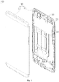
Fig. 1 illustrates an exploded perspective view of an electronic device of an embodiment of the present disclosure. -
Fig. 2 illustrates a partial sectional view of an electronic device of an embodiment of the present disclosure. -
Fig. 3 illustrates an enlarged view of portion III of the electronic device inFig. 2 . -
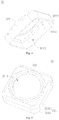
Fig. 4 illustrates a perspective view of a sealing member of a laser projection structure of an embodiment of the present disclosure. -
Fig. 5 illustrates a perspective view of a sealing member of a laser projection structure of an embodiment of the present disclosure in another angle. -
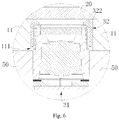
Fig. 6 illustrates a partial sectional view of an electronic device of another embodiment of the present disclosure. -
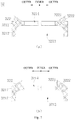
Fig. 7 illustrates a sectional view of a sealing member of a laser projection structure of an embodiment of the present disclosure. -
Figs. 8 to 10 illustrate partial schematic views of a laser projector of a laser projection structure of an embodiment of the present disclosure. - Specific embodiments of the present disclosure will be described further with reference to accompanying drawings. The same or similar reference numerals are used to indicate same or similar members or members with same or similar functions throughout the description.
- Additionally, the embodiments of the present disclosure described herein with reference to drawings are explanatory, illustrative, and used to generally understand the present disclosure. The embodiments shall not be construed to limit the present disclosure.
- In the present disclosure, unless specified or limited otherwise, a structure in which a first feature is "on" or "below" a second feature may include an embodiment in which the first feature is in direct contact with the second feature, and may also include an embodiment in which the first feature and the second feature are not in direct contact with each other, but are contacted via an additional feature formed therebetween. Furthermore, a first feature "on," "above," or "on top of' a second feature may include an embodiment in which the first feature is right or obliquely "on," "above," or "on top of' the second feature, or just means that the first feature is at a height higher than that of the second feature. While a first feature "below," "under," or "on bottom of' a second feature may include an embodiment in which the first feature is right or obliquely "below," "under," or "on bottom of' the second feature, or just means that the first feature is at a height lower than that of the second feature.
- Embodiments of the present disclosure provide a laser projection structure and an electronic device.
- The laser projection structure according to embodiments of the present disclosure includes a laser projector and a sealing member. The laser projector has a light emitting face. The sealing member includes a body and a resisting portion, the body is provided to the light emitting face, and the resisting portion extends from the body in a light emission direction of the laser projector.
- The electronic device according to embodiments of the present disclosure includes a housing, a cover plate and the laser projection structure. The cover plate is mounted to the housing, and the laser projection structure includes a laser projector and a sealing member. The laser projector has a light emitting face. The sealing member includes a body and a resisting portion, the body is provided to the light emitting face, and the resisting portion extends from the body in a light emission direction of the laser projector; the laser projection structure is mounted in the housing, the light emitting face faces the cover plate, and the resisting portion abuts against the cover plate and is configured to seal a gap between the light emitting face and the cover plate.
- A
laser projection structure 30 according to embodiments of the present disclosure includes alaser projector 31 and a sealingmember 32. Thelaser projector 31 has alight emitting face 3161. The sealingmember 32 includes abody 321 and a resistingportion 322, thebody 321 is provided to thelight emitting face 3161 and joined to thelaser projector 31, and the resistingportion 322 extends from thebody 321 in a light emission direction of thelaser projector 31. - In some embodiments, the
laser projector 31 includes a light emitting opening 317 defined in thelight emitting face 3161, and the resistingportion 322 is formed in a ring shape and provided around thelight emitting opening 317. - In some embodiments, a width of a section of the resisting
portion 322 gradually decreases in the light emission direction of thelaser projector 31. - In some embodiments, the resisting
portion 322 includes aninner side wall 3221 and anouter side wall 3222, and in the light emission direction of thelaser projector 31, theinner side wall 3221 is inclined outwards, and/or theouter side wall 3222 is inclined inwards. - In some embodiments, the
body 321 defines anaccommodating cavity 3213, and thebody 321 is fitted over thelaser projector 31 such that thelaser projector 31 extends into theaccommodating cavity 3213. - In some embodiments, the
laser projector 31 includes alens barrel 312, and thebody 321 is fitted over thelens barrel 312. - In some embodiments, the
laser projector 31 includes alens barrel 312, adiffractive element 315 and aprotective cover 316. Thediffractive element 315 is received in thelens barrel 312, theprotective cover 316 is mounted to thelens barrel 312 to prevent thediffractive element 315 from coming out of thelens barrel 312, and thebody 312 is fitted over theprotective cover 316. - In some embodiments, the
body 321 includes a top 3211 and aside 3212. The top 3211 is attached to theprotective cover 316, theside 3212 extends from the top 3211, and theside 3212 and the top 3211 cooperatively define theaccommodating cavity 3213. - In some embodiments, the resisting
portion 322 includes theinner side wall 3221 and theouter side wall 3222; in the light emission direction of thelaser projector 31, theinner side wall 3221 is inclined outwards, and theouter side wall 3222 is perpendicular to the top 3211; or in the light emission direction of thelaser projector 31, theouter side wall 3222 is inclined inwards, and theinner side wall 3221 is perpendicular to the top 3211. - In some embodiments, the sealing
member 32 is made of silicone or rubber. - The
electronic device 100 according to embodiments of the present disclosure includes ahousing 10, acover plate 20 and thelaser projection structure 30 according to any of the above-described embodiments. Thecover plate 20 is mounted to thehousing 10. Thelaser projection structure 30 is mounted in thehousing 10, thelight emitting face 3161 faces thecover plate 20, and the resistingportion 322 abuts against thecover plate 20 and serves to seal a gap between thelight emitting face 3161 and thecover plate 20. - In some embodiments, the
housing 10 includes afront casing 11 and arear casing 12, and thecover plate 20 is mounted to thefront casing 11, thelaser projection structure 30 is mounted to thefront casing 11, and therear casing 12 abuts against a side of thelaser projector 31 opposite to thelight emitting face 3161; or theelectronic device 100 further includes abracket 50 mounted between thefront casing 11 and therear casing 12, and thelaser projection structure 30 is mounted to thebracket 50. - As illustrated in
Fig. 1 , theelectronic device 100 according to embodiments of the present disclosure includes thehousing 10, thecover plate 20 and thelaser projection structure 30. Theelectronic device 100 may be a mobile phone, a tablet computer, a notebook computer, a game machine, a head-mounted display device, an access control system, a teller machine, or the like. In embodiments of the present disclosure, theelectronic device 100 is exemplified by the mobile phone. It could be understood that, specific form of theelectronic device 100 may be others, which is not limited herein. - As illustrated in
Fig. 2 , thehousing 10 may serve as an outer casing of theelectronic device 100, thehousing 10 may serve as a mounting support for thecover plate 20 and thelaser projection structure 30 and may provide dustproof, waterproof and shatterproof protection for thelaser projection structure 30, and a display screen, a battery or other components may be mounted to thehousing 10. In embodiments of the present disclosure, thehousing 10 includes thefront casing 11 and therear casing 12, thefront casing 11 and therear casing 12 are joined to each other, and thelaser projection structure 30 is received between thefront casing 11 and therear casing 12. Thefront casing 11 and therear casing 12 may be made of materials such as stainless steel, aluminum alloy, plastic, etc. Thefront casing 11 may also define a throughhole 111, functional modules of theelectronic device 100, such as thelaser projection structure 30, an infrared imaging module, a visible light imaging module, a receiver, etc., may be inserted into the throughhole 111, and emit signals such as optical signal, acoustic signal to the outside or receive optical signal or the like from the outside. - The
cover plate 20 is mounted to thehousing 10. Specifically, in the embodiments of the present disclosure, thecover plate 20 is mounted to thefront casing 11, and thecover plate 20 and thelaser projection structure 30 are mounted to thefront casing 11 from two opposite sides of thefront casing 11. Thecover plate 20 is mounted to thefront casing 11 so as to cover the display screen of theelectronic device 100. Thecover plate 20 may be light transparent, and may be made of light transparent glass, resin, plastic and so on. - As illustrated in
Figs. 1 and2 , thelaser projection structure 30 is mounted in thehousing 10. In the embodiments of the present disclosure, thelaser projection structure 30 is mounted to thefront casing 11. Specifically, thelaser projection structure 30 is inserted into the throughhole 111 of thefront casing 11 to be mounted to thefront casing 11, and glue may be filled between thelaser projection structure 30 and an inner wall of the throughhole 111 to assist fixation of thelaser projection structure 30. Two sides of thelaser projection structure 30 abut against thecover plate 20 and therear casing 12 respectively to further fix thelaser projection structure 30. Thelaser projection structure 30 includes thelaser projector 31 and the sealingmember 32. - The
laser projector 31 includes asubstrate assembly 311, thelens barrel 312, alight source 313, acollimating element 314, thediffractive element 315 and theprotective cover 316. Thesubstrate assembly 311 includes asubstrate 3112 and acircuit board 3111, thecircuit board 3111 is provided to thesubstrate 3112, and thecircuit board 3111 is configured to be electrically coupled to amain board 40 of theelectronic device 100. Thecircuit board 3111 may be a printed circuit board, a flexible circuit board or a rigid-flex board. Thelens barrel 312 is provided to thesubstrate assembly 311, and thelens barrel 312 defines a hollow cavity. Thelight source 313 is provided to thesubstrate assembly 311 and may be provided in areceiving hole 3113 of thecircuit board 3111 and electrically coupled to thecircuit board 3111 through a wire (not illustrated). Thelight source 313 may be a vertical cavity surface emitting laser (VCSEL) or an edge-emitting laser (EEL). Driven by electric power, thelight source 313 emits laser, and the laser may be infrared light. Thecollimating element 314 is provided in thelens barrel 312, thecollimating element 314 may be a lens and is configured to collimate the laser emitted from thelight source 313. Thediffractive element 315 is provided in thelens barrel 312, and the laser collimated by thecollimating element 314 passes through thediffractive element 315. Thediffractive element 315 diffracts the laser into a predetermined laser pattern, and the laser is sent out from thelaser projector 31. Theprotective cover 316 is mounted to thelens barrel 312. Specifically, theprotective cover 316 covers thelens barrel 312, theprotective cover 316 and thelens barrel 312 may be fixedly coupled in a detachable manner, and theprotective cover 316 is configured to restrict thediffractive element 315 in thelens barrel 312 to prevent thediffractive element 315 from coming out of thelens barrel 312. Thelaser projector 31 has thelight emitting face 3161, thelight emitting face 3161 faces thecover plate 20, a side of thelaser projector 31 opposite to thelight emitting face 3161 abuts against therear casing 12, the laser passes through thelight emitting face 3161 and exits from thelaser projector 31, and the laser then passes through thecover plate 20 and exits from theelectronic device 100. Specifically, thelight emitting face 3161 defines thelight emitting opening 317, the laser passes through the light emitting opening 317 to exit from thelaser projector 31. In embodiments of the present disclosure, thelight emitting opening 317 is defined in theprotective cover 316. - As illustrated in
Figs. 2 and 3 , the sealingmember 32 is mounted to thelaser projector 31, the sealingmember 32 is configured to seal a gap between thelight emitting face 3161 and thecover plate 20, so as to prevent impurities such as dust or moisture from entering thelaser projector 31 through thelight emitting opening 317. The sealingmember 32 includes thebody 321 and the resistingportion 322. The sealingmember 32 may be made of a material having good elasticity, for example, the sealingmember 32 may be made of silicone or rubber, etc. - As illustrated in
Figs. 4 and 5 , thebody 321 is fixedly coupled to thelaser projector 31. Specifically, thebody 321 is provided to thelight emitting face 3161 and fixedly coupled to thelaser projector 31. In embodiments of the present disclosure, thebody 321 is fixed to theprotective cover 316, and thebody 321 includes the top 3211 and theside 3212. The top 3211 is attached to theprotective cover 316, and the top 3211 defines alight passage opening 3214, and thelight passage opening 3214 is aligned with thelight emitting opening 317. Theside 3212 extends from the top 3211, and theside 3212 and the top 3211 cooperatively define theaccommodating cavity 3213. Thebody 321 is fitted over thelaser projector 31 to extend thelaser projector 31 into theaccommodating cavity 3213. Specifically, theprotective cover 316 extends into theaccommodating cavity 3213, such that thebody 321 is fitted over theprotective cover 316. A shape of theaccommodating cavity 3213 may be similar to a shape and a size of theprotective cover 316, and thebody 321 may tightly wrap theprotective cover 316, such that thebody 321 and theprotective cover 316 can be joined together in a better way. - The resisting
portion 322 extends from thebody 321 in the light emission direction of the laser projector 31 (such as an X direction illustrated inFig. 2 ). Specifically, the resistingportion 322 extends from the top 3211 of thebody 321. The resistingportion 322 is configured to abut against thecover plate 20 so as to seal the gap between thelight emitting face 3161 and thecover plate 20, a top end of the resistingportion 322 is squeezed and then elastically deformed to be more tightly attached to thecover plate 20, and the dust, the moisture, or the like cannot easily enter thelaser projection structure 30 via the gap between the resistingportion 322 and thecover plate 20. In embodiments of the present disclosure, the resistingportion 322 is formed in the ring shape and provided around thelight emitting opening 317. Specifically, the resistingportion 322 may be a circular ring shape, a rectangular ring shape, an elliptical ring shape, or other shapes, and the resistingportion 322 is provided around the light emitting opening 317 to prevent the impurities from entering the light emitting opening 317 from a plurality of directions, and provide protection for thelaser projector 31 in a better way. - The resisting
portion 322 includes theinner side wall 3221 and theouter side wall 3222, theinner side wall 3221 is closer to thelight passage opening 3214 than theouter side wall 3222, and theinner side wall 3221 and theouter side wall 3222 are intersected at the top end of the resistingportion 322. Theinner side wall 3221 and theouter side wall 3222 may be simultaneously deformed when this top end is squeezed. In embodiments of the present disclosure, in the light emission direction of thelaser projector 31, a width of a section of the resistingportion 322 gradually decreases. That is to say, in the light emission direction of thelaser projector 31, a distance between theinner side wall 3221 and theouter side wall 3222 gradually decreases, such that stress is relatively concentrated at a portion of the resistingportion 322 resisting against thecover plate 20, the resistingportion 322 is more tightly attached to thecover plate 20, and the resistingportion 322 has better sealing effect. In the embodiment illustrated inFig. 3 , in the light emission direction of thelaser projector 31, theinner side wall 3221 is inclined outwards, and theouter side wall 3222 is inclined inwards. In embodiments of the present disclosure, the light emission direction is the same as a direction in which thelight emitting face 3161 is directed at thecover plate 20. - During the installation of the
electronic device 100, the sealingmember 32 may be mounted in thelaser projector 31 so that thelaser projection structure 30 is constituted, then thelaser projection structure 30 may be mounted in the throughhole 111 of thefront casing 11, then therear casing 12 may be joined to thefront casing 11 to render therear casing 12 to abut against a side of thelaser projector 31, and finally thecover plate 20 may be joined to thefront casing 11, such that thecover plate 20 abuts against the resistingportion 322 of the sealingmember 32. Also, thecover plate 20 may be first joined to thefront casing 11, then thelaser projection structure 30 may be mounted in the throughhole 111 of thefront casing 11 in which case the resistingportion 322 contacts thecover plate 20, and finally therear casing 12 is joined to thefront casing 11 and therear casing 12 abuts against thelaser projector 31, such that thelaser projector 31 squeezes the sealing member 21, and the resistingportion 322 is squeezed and deformed to be tightly attached to thecover plate 20. - In the related art, the dust or other impurities can easily enter an interior of the structured light projector through the light emitting face of the structured light projector, resulting in that the structured light projector cannot operate normally. In the
electronic device 100 of embodiments of the present disclosure, the resistingportion 322 of the sealingmember 32 extends from thebody 321 in the light emission direction of thelaser projector 31 and abuts against thecover plate 20. The resistingportion 322 can seal the gap between thelight emitting face 3161 of thelaser projector 31 and thecover plate 20, to prevent the dust or other impurities from entering the interior of thelaser projector 31. - As illustrated in
Figs. 1 and6 , in some embodiments, theelectronic device 100 further includes thebracket 50 mounted between thefront casing 11 and therear casing 12, and thelaser projection structure 30 is mounted to thebracket 50. Specifically, thelaser projector 31 is mounted to thebracket 50 and protrudes from thebracket 50, a portion of thelaser projector 31 protruding from thebracket 50 and the sealingmember 32 together pass through the throughhole 111 of thefront casing 11. The resistingportion 322 of the sealingmember 32 abuts against thecover plate 20. - As illustrated in
Fig. 2 , in some embodiments, thelaser projector 31 may also not include theprotective cover 316, thelight emitting face 3161 is a top face of thelens barrel 312, thebody 321 of the sealingmember 32 is directly fitted over thelens barrel 312. The top 3211 of thebody 321 is joined to thelight emitting face 3161, theside 3212 of thebody 321 is fitted over thelens barrel 312, and meanwhile the top 3211 of thebody 321 can prevent thediffractive element 315 from coming out of thelens barrel 312. - As illustrated in
Figs. 2 and 3 , in some embodiments, the specific structure of thebody 321 is not limited by the above discussion. In an example, thebody 321 may not include theabove side 3212 and not define theaccommodating cavity 3213, the top 3211 of thebody 321 is directly joined to theprotective cover 316, for example, the top 3211 is secured to theprotective cover 316 by gluing, and the resistingportion 322 extends from thebody 321. - As illustrated in
Figs. 3 and7 , in some embodiments, the extending directions of theinner side wall 3221 and theouter side wall 3222 of the resistingportion 322 may also have other forms. In an example illustrated inFig. 7a , in the light emission direction of thelaser projector 31, theinner side wall 3221 may be inclined outwards, and theouter side wall 3222 is perpendicular to the top 3211. Thus, when the resistingportion 322 is squeezed by thecover plate 20, the resistingportion 322 will be inclined outwards rather than inclined inwards, so as to prevent the resistingportion 322 from covering thelight passage opening 3214. In an example illustrated inFig. 7b , in the light emission direction of thelaser projector 31, theouter side wall 3222 may also be inclined inwards, and theinner side wall 3221 is perpendicular to the top 3211. - As illustrated in
Figs. 2 and8 , in some embodiments, thelight source 313 is configured as an edge-emittinglaser 313. Specifically, the edge-emittinglaser 313 may be a distributed feedback laser (DFB). The edge-emittinglaser 313 is in a column shape as a whole, an end face of the edge-emittinglaser 313 away from thesubstrate assembly 311 has thelight emitting face 3131, the laser is emitted from thelight emitting face 3131, and thelight emitting face 3131 faces thecollimating element 314. By employing the edge-emittinglaser 313 as the light source, on one hand, the edge-emittinglaser 313 has smaller temperature drift than the VCSEL array; on the other hand, since the edge-emittinglaser 313 is a single-point light emitting structure without need for designing the array structure, the fabrication is simple, and the cost of thelight source 313 of thelaser projector 31 is lower. - As illustrated in
Fig. 9 , in some embodiments, thelaser projector 31 further includes a fixing member 318, and the fixing member 318 is configured to fix the edge-emittinglaser 313 to thesubstrate assembly 311. During propagation of the laser of the distributed feedback laser, power gain is obtained by means of feedback of a grating structure. In order to improve the power of the distributed feedback laser, it is necessary to increase an input current and/or increase the length of the distributed feedback laser. Since the increased input current will make power consumption of the distributed feedback laser increase and cause serious heat generation problem, the length of the distributed feedback laser needs to be increased in order to ensure the normal operation of the distributed feedback laser, such that the distributed feedback laser generally is formed in an elongated strip structure. When thelight emitting face 3131 of the edge-emittinglaser 313 faces thecollimating element 314, the edge-emittinglaser 313 is arranged vertically. Since the edge-emittinglaser 313 is formed in the elongated strip structure, accidents such as drop, displacement or wobbling can easily happen to the edge-emittinglaser 313. Thus, the edge-emittinglaser 313 can be fixed by providing the fixing member 318, to prevent accidents such as drop, displacement or wobbling from happening to the edge-emittinglaser 313. - Specifically, in some embodiments, the fixing member 318 includes a sealing adhesive 3181, and the sealing adhesive 3181 is provided between the edge-emitting
laser 313 and thesubstrate assembly 311. More specifically, in an example illustrated inFig. 8 , a face of the edge-emittinglaser 313 opposite to thelight emitting face 3131 is adhered to the substrate assembly 311 (specifically substrate 3112). In an example illustrated inFig. 9 , aside face 3132 of the edge-emittinglaser 313 may also be adhered to thesubstrate assembly 311. The sealing adhesive 3181 wraps the periphery of theside face 3132, or may merely adhere one face of theside face 3132 to thesubstrate assembly 311 or adhere some faces of theside face 3132 to thesubstrate assembly 311. Further, the sealing adhesive 3181 may be a thermally conductive adhesive to transfer heat produced by the operation of thelight source 313 to thesubstrate assembly 311. - As illustrated in
Fig. 10 , in some embodiments, the fixing member 318 includes asupport frame 3182, thesupport frame 3182 is provided to thesubstrate assembly 311, and the edge-emittinglaser 313 is secured to thesupport frame 3182. A plurality of support frames 3182 may be provided, the plurality ofsupport frames 3182 can cooperatively surround the edge-emittinglaser 313, and the edge-emittinglaser 313 can be mounted among the plurality ofsupport frames 3182 when mounted. In an example, the plurality ofsupport frames 3182 cooperatively clamp the edge-emittinglaser 313 to further prevent the edge-emittinglaser 313 from wobbling. Thesupport frame 3182 may be elastic, and when the edge-emittinglaser 313 is clamped among the plurality of support frames 3182, the plurality of support frames 3182 is stretched and clamps the edge-emittinglaser 313. - Reference throughout this specification to "an embodiment," "some embodiments," "an illustrative embodiment," "an example," "a specific example," or "some examples," means that a particular feature, structure, material, or characteristic described in connection with the embodiment or example is included in at least one embodiment or example of the present disclosure. Thus, the appearances of the phrases in various places throughout this specification are not necessarily referring to the same embodiment or example of the present disclosure. Furthermore, the particular features, structures, materials, or characteristics may be combined in any suitable manner in one or more embodiments or examples.
- In addition, terms such as "first" and "second" are used herein for purposes of description and are not intended to indicate or imply relative importance or significance. Thus, the feature defined with "first" and "second" may comprise one or more of this feature. In the description of the present disclosure, the term "a plurality of' means two or more than two, unless specified otherwise.
- Although explanatory embodiments of the present disclosure have been shown and described, it would be appreciated by those skilled in the art that the above embodiments are exemplary and cannot be construed to limit the present disclosure, and changes, alternatives, and modifications can be made in the embodiments without departing from the scope of the present disclosure as defined by the appended claims.
Claims (13)
- A laser projection structure (30), comprising:a laser projector (31) having a light emitting face (3161) and comprising a lens barrel (312), a diffractive element (315) and a protective cover (316), the diffractive element (315) being received in the lens barrel (312), the protective cover (316) being mounted to the lens barrel (312) to prevent the diffractive element (315) from coming out of the lens barrel (312); anda sealing member (32) comprising a body (321) and a resisting portion (322), the body (321) being provided to the light emitting face (3161) and being fitted over the protective cover (316), and the resisting portion (322) extending from the body (321) in a light emission direction of the laser projector (31) and configured to abut against an external cover plate (20).
- The laser projection structure (30) according to claim 1, wherein the laser projector (31) comprises a light emitting opening (317) defined in the light emitting face (3161), and the resisting portion (322) is formed in a ring shape and configured to surround the light emitting opening (317).
- The laser projection structure (30) according to claim 1 or 2, wherein a width of a section of the resisting portion (322) gradually decreases in the light emission direction of the laser projector (31).
- The laser projection structure (30) according to any one of claims 1 to 3, wherein the resisting portion (322) comprises an inner side wall and an outer side wall, and in the light emission direction of the laser projector (31), the inner side wall is inclined outwards, and/or the outer side wall is inclined inwards.
- The laser projection structure (30) according to any one of claims 1 to 4, wherein the body (321) defines an accommodating cavity (3213) and is fitted over the laser projector (31) such that the laser projector (31) extends into the accommodating cavity (3213).
- The laser projection structure (30) according to claim 1, wherein the body (321) comprises a top and a side, the top is attached to the protective cover (316), the side extends from the top, and the side and the top cooperatively define the accommodating cavity (3213).
- The laser projection structure (30) according to claim 6, wherein the resisting portion (322) comprises an inner side wall and an outer side wall;in the light emission direction of the laser projector (31), the inner side wall is inclined outwards, and the outer side wall is perpendicular to the top; orin the light emission direction of the laser projector (31), the outer side wall is inclined inwards, and the inner side wall is perpendicular to the top.
- The laser projection structure (30) according to any one of claims 1 to 7, wherein the sealing member (32) is made of silicone or rubber.
- An electronic device (100), comprising a housing (10), a cover plate (20) and a laser projection structure (30), the cover plate (20) being mounted to the housing (10), and the laser projection structure (30) comprising:a laser projector (31) having a light emitting face (3161) and comprising a lens barrel (312), a diffractive element (315) and a protective cover (316), the diffractive element (315) being received in the lens barrel (312), the protective cover (316) being mounted to the lens barrel (312) to prevent the diffractive element (315) from coming out of the lens barrel (312); anda sealing member (32) comprising a body (321) and a resisting portion (322), the body (321) defining an accommodating cavity (3213) and being fitted over the protective cover (316), and the resisting portion (322) extending from the body (321) in a light emission direction of the laser projector (31);wherein the laser projection structure (30) is mounted in the housing (10), the light emitting face (3161) faces the cover plate (20), and the resisting portion (322) abuts against the cover plate (20) and is configured to seal a gap between the light emitting face (3161) and the cover plate (20).
- The electronic device (100) according to claim 9, wherein the body (321) comprises a top and a side, the top is attached to the laser projector (31), the side extends from the top, and the side and the top cooperatively define the accommodating cavity (3213).
- The electronic device (100) according to claim 9 or 10, wherein the housing (10) comprises a front casing (11) and a rear casing (12), the cover plate (20) is mounted to the front casing (11),the laser projection structure (30) is mounted to the front casing (11), and the rear casing (12) abuts against a side of the laser projector (31) opposite to the light emitting face (3161); orthe electronic device (100) further comprises a bracket (50) mounted between the front casing (11) and the rear casing (12), and the laser projection structure (30) is mounted to the bracket (50).
- The electronic device (100) according to claim 11, wherein the front casing (11) defines a through hole (111), the laser projection structure (30) is inserted into the through hole (111) to be mounted to the front casing (11), and glue is filled between the laser projection structure (30) and an inner wall of the through hole (111).
- The electronic device (100) according to any one of claims 9 to 12, wherein the laser projector (31) comprises a light emitting opening (317) defined in the light emitting face (3161), and the resisting portion (322) is formed in a ring shape and configured to surround the light emitting opening (317).
Applications Claiming Priority (1)
| Application Number | Priority Date | Filing Date | Title |
|---|---|---|---|
| CN201810317072.7A CN108627936B (en) | 2018-04-10 | 2018-04-10 | Laser Projection Structures and Electronics |
Publications (2)
| Publication Number | Publication Date |
|---|---|
| EP3553582A1 EP3553582A1 (en) | 2019-10-16 |
| EP3553582B1 true EP3553582B1 (en) | 2021-10-27 |
Family
ID=63705043
Family Applications (1)
| Application Number | Title | Priority Date | Filing Date |
|---|---|---|---|
| EP19168059.4A Active EP3553582B1 (en) | 2018-04-10 | 2019-04-09 | Laser projection structure and electronic device |
Country Status (5)
| Country | Link |
|---|---|
| US (1) | US11163225B2 (en) |
| EP (1) | EP3553582B1 (en) |
| CN (1) | CN108627936B (en) |
| TW (1) | TWI677714B (en) |
| WO (1) | WO2019196525A1 (en) |
Families Citing this family (11)
| Publication number | Priority date | Publication date | Assignee | Title |
|---|---|---|---|---|
| CN108627936B (en) * | 2018-04-10 | 2020-02-21 | Oppo广东移动通信有限公司 | Laser Projection Structures and Electronics |
| CN109212879A (en) * | 2018-10-25 | 2019-01-15 | 深圳阜时科技有限公司 | A kind of functionalization mould group, sensing device and equipment |
| CN115685658B (en) * | 2019-01-10 | 2025-11-14 | 青岛海信激光显示股份有限公司 | A laser light source and laser projection device |
| US11592145B2 (en) | 2019-01-10 | 2023-02-28 | Hisense Laser Display Co., Ltd. | Laser light source and laser projection device |
| US11570411B2 (en) | 2019-01-10 | 2023-01-31 | Hisense Laser Display Co., Ltd. | Laser light source and laser projection device |
| CN210093396U (en) * | 2019-01-17 | 2020-02-18 | 深圳市光鉴科技有限公司 | A3D camera module and electronic equipment for under screen |
| CN110955006A (en) * | 2019-12-18 | 2020-04-03 | 湖北航天技术研究院总体设计所 | Light beam emission lens cone protective cover |
| CN111090161A (en) * | 2019-12-27 | 2020-05-01 | 豪威光电子科技(上海)有限公司 | Lens module and camera |
| CN111385452B (en) * | 2020-03-18 | 2021-08-24 | Oppo广东移动通信有限公司 | an electronic device |
| CN112037673B (en) * | 2020-09-16 | 2022-07-15 | 中航华东光电有限公司 | Micro OLED head imaging source product framework |
| CN113216029B (en) * | 2021-04-15 | 2024-08-23 | 山西路泽交通科技有限公司 | Universal adjusting laser device |
Family Cites Families (21)
| Publication number | Priority date | Publication date | Assignee | Title |
|---|---|---|---|---|
| US5838703A (en) | 1996-09-30 | 1998-11-17 | Motorola, Inc. | Semiconductor laser package with power monitoring system and optical element |
| JP2002071923A (en) | 2000-08-29 | 2002-03-12 | Canon Inc | Method for manufacturing diffractive optical element, diffractive optical element, optical system having the diffractive optical element, photographing apparatus and observation apparatus having the optical system |
| US7646544B2 (en) | 2005-05-14 | 2010-01-12 | Batchko Robert G | Fluidic optical devices |
| JP4451771B2 (en) * | 2004-12-27 | 2010-04-14 | アルファナテクノロジー株式会社 | Spindle motor |
| CN201780442U (en) * | 2010-08-16 | 2011-03-30 | 青岛海信移动通信技术股份有限公司 | Camera dustproof structure and portable mobile terminal |
| US20120206046A1 (en) * | 2011-02-14 | 2012-08-16 | Chao-Chi Huang | Laser module |
| US8606057B1 (en) | 2012-11-02 | 2013-12-10 | Heptagon Micro Optics Pte. Ltd. | Opto-electronic modules including electrically conductive connections for integration with an electronic device |
| CN203800971U (en) | 2013-05-21 | 2014-08-27 | 上海鼎讯电子有限公司 | A shock-absorbing sealing structure for mobile phone camera |
| CN203574741U (en) * | 2013-07-11 | 2014-04-30 | 北京小米科技有限责任公司 | Electronic equipment, automatic-focusing camera thereof, and housing of electronic equipment |
| KR101785879B1 (en) * | 2014-07-23 | 2017-10-16 | 헵타곤 마이크로 옵틱스 피티이. 리미티드 | Light emitter and light detector modules including vertical alignment features |
| US10234695B2 (en) | 2015-02-16 | 2019-03-19 | Apple Inc. | Low-temperature hermetic sealing for diffractive optical element stacks |
| CN105120017B (en) | 2015-07-16 | 2017-03-08 | 广东欧珀移动通信有限公司 | Terminal device |
| EP3340601B1 (en) | 2015-08-17 | 2019-12-18 | LG Innotek Co., Ltd. | Camera module |
| CN204993600U (en) * | 2015-10-09 | 2016-01-20 | 周旗辉 | Dustproof lens mount |
| CN205490686U (en) | 2015-12-31 | 2016-08-17 | 上海与德通讯技术有限公司 | Back camera casing fixed knot constructs and mobile terminal |
| CN206023923U (en) * | 2016-08-12 | 2017-03-15 | 珠海市魅族科技有限公司 | Electronic installation |
| CN206877030U (en) * | 2017-07-07 | 2018-01-12 | 深圳奥比中光科技有限公司 | Light-emitting device and its laser projection module |
| CN107343122A (en) | 2017-08-02 | 2017-11-10 | 深圳奥比中光科技有限公司 | 3D imaging devices |
| CN108415178B (en) * | 2018-04-10 | 2024-04-05 | Oppo广东移动通信有限公司 | Protection component of laser projector, laser projection structure and electronic device |
| CN208110176U (en) * | 2018-04-10 | 2018-11-16 | Oppo广东移动通信有限公司 | Protective component, laser projection structure and electronics for laser projector |
| CN108627936B (en) * | 2018-04-10 | 2020-02-21 | Oppo广东移动通信有限公司 | Laser Projection Structures and Electronics |
-
2018
- 2018-04-10 CN CN201810317072.7A patent/CN108627936B/en active Active
-
2019
- 2019-01-08 WO PCT/CN2019/070766 patent/WO2019196525A1/en not_active Ceased
- 2019-04-03 US US16/374,223 patent/US11163225B2/en active Active
- 2019-04-09 EP EP19168059.4A patent/EP3553582B1/en active Active
- 2019-04-09 TW TW108112303A patent/TWI677714B/en not_active IP Right Cessation
Also Published As
| Publication number | Publication date |
|---|---|
| TW201944122A (en) | 2019-11-16 |
| US11163225B2 (en) | 2021-11-02 |
| WO2019196525A1 (en) | 2019-10-17 |
| US20190310542A1 (en) | 2019-10-10 |
| EP3553582A1 (en) | 2019-10-16 |
| CN108627936A (en) | 2018-10-09 |
| TWI677714B (en) | 2019-11-21 |
| CN108627936B (en) | 2020-02-21 |
Similar Documents
| Publication | Publication Date | Title |
|---|---|---|
| EP3553582B1 (en) | Laser projection structure and electronic device | |
| KR102494677B1 (en) | Bracket assempbly for a multi-component vision system in an electronic device | |
| EP3550340B1 (en) | Diffractive optical assembly, laser projection unit, depth camera and electronic device | |
| CN108735098B (en) | Frame assembly for electronic device displays | |
| US10823852B2 (en) | Laser projector, camera unit and electronic device | |
| US11525669B2 (en) | Laser projection module, depth camera and electronic device | |
| CN108508622A (en) | Laser projection module, depth camera and electronic device | |
| CN108415178B (en) | Protection component of laser projector, laser projection structure and electronic device | |
| US11330090B2 (en) | Bracket, input/output assembly and terminal | |
| CN208110176U (en) | Protective component, laser projection structure and electronics for laser projector | |
| CN207780465U (en) | Laser projection module, depth camera and electronic device | |
| CN108490572B (en) | Laser projection modules, depth cameras and electronic devices | |
| CN108535828A (en) | Diffractive optical element, laser projection module, depth camera and electronic device | |
| HK40014412B (en) | Laser projection structure and electronic device | |
| HK40014412A (en) | Laser projection structure and electronic device | |
| CN207780464U (en) | Laser projection module, depth camera and electronic device | |
| CN108344374A (en) | Laser projection module, depth camera and electronic device | |
| CN208386608U (en) | Bracket, in-out box and terminal | |
| CN108600438A (en) | Support structure, input/output assembly and mobile terminal | |
| CN208386604U (en) | Frames, I/O components and electronic devices | |
| CN208386609U (en) | Bracket, in-out box and terminal | |
| CN208386606U (en) | Frames, input and output components and electronic devices | |
| CN208386605U (en) | Bracket, in-out box and electronic device | |
| US20240310667A1 (en) | Display device, watch, and display device manufacturing method | |
| JP2020098258A (en) | Optical module and electronic device |
Legal Events
| Date | Code | Title | Description |
|---|---|---|---|
| PUAI | Public reference made under article 153(3) epc to a published international application that has entered the european phase |
Free format text: ORIGINAL CODE: 0009012 |
|
| STAA | Information on the status of an ep patent application or granted ep patent |
Free format text: STATUS: THE APPLICATION HAS BEEN PUBLISHED |
|
| AK | Designated contracting states |
Kind code of ref document: A1 Designated state(s): AL AT BE BG CH CY CZ DE DK EE ES FI FR GB GR HR HU IE IS IT LI LT LU LV MC MK MT NL NO PL PT RO RS SE SI SK SM TR |
|
| AX | Request for extension of the european patent |
Extension state: BA ME |
|
| STAA | Information on the status of an ep patent application or granted ep patent |
Free format text: STATUS: REQUEST FOR EXAMINATION WAS MADE |
|
| 17P | Request for examination filed |
Effective date: 20191016 |
|
| RBV | Designated contracting states (corrected) |
Designated state(s): AL AT BE BG CH CY CZ DE DK EE ES FI FR GB GR HR HU IE IS IT LI LT LU LV MC MK MT NL NO PL PT RO RS SE SI SK SM TR |
|
| RAP1 | Party data changed (applicant data changed or rights of an application transferred) |
Owner name: GUANGDONG OPPO MOBILE TELECOMMUNICATIONS CORP., LT |
|
| REG | Reference to a national code |
Ref country code: HK Ref legal event code: DE Ref document number: 40014412 Country of ref document: HK |
|
| GRAP | Despatch of communication of intention to grant a patent |
Free format text: ORIGINAL CODE: EPIDOSNIGR1 |
|
| STAA | Information on the status of an ep patent application or granted ep patent |
Free format text: STATUS: GRANT OF PATENT IS INTENDED |
|
| RIC1 | Information provided on ipc code assigned before grant |
Ipc: H01S 3/02 20060101ALI20210519BHEP Ipc: G03B 21/20 20060101ALI20210519BHEP Ipc: G02B 5/18 20060101ALI20210519BHEP Ipc: G02B 7/02 20210101AFI20210519BHEP |
|
| INTG | Intention to grant announced |
Effective date: 20210622 |
|
| GRAS | Grant fee paid |
Free format text: ORIGINAL CODE: EPIDOSNIGR3 |
|
| GRAA | (expected) grant |
Free format text: ORIGINAL CODE: 0009210 |
|
| STAA | Information on the status of an ep patent application or granted ep patent |
Free format text: STATUS: THE PATENT HAS BEEN GRANTED |
|
| AK | Designated contracting states |
Kind code of ref document: B1 Designated state(s): AL AT BE BG CH CY CZ DE DK EE ES FI FR GB GR HR HU IE IS IT LI LT LU LV MC MK MT NL NO PL PT RO RS SE SI SK SM TR |
|
| REG | Reference to a national code |
Ref country code: GB Ref legal event code: FG4D |
|
| REG | Reference to a national code |
Ref country code: CH Ref legal event code: EP |
|
| REG | Reference to a national code |
Ref country code: DE Ref legal event code: R096 Ref document number: 602019008603 Country of ref document: DE |
|
| REG | Reference to a national code |
Ref country code: AT Ref legal event code: REF Ref document number: 1442291 Country of ref document: AT Kind code of ref document: T Effective date: 20211115 |
|
| REG | Reference to a national code |
Ref country code: IE Ref legal event code: FG4D |
|
| REG | Reference to a national code |
Ref country code: LT Ref legal event code: MG9D |
|
| REG | Reference to a national code |
Ref country code: NL Ref legal event code: MP Effective date: 20211027 |
|
| REG | Reference to a national code |
Ref country code: AT Ref legal event code: MK05 Ref document number: 1442291 Country of ref document: AT Kind code of ref document: T Effective date: 20211027 |
|
| PG25 | Lapsed in a contracting state [announced via postgrant information from national office to epo] |
Ref country code: RS Free format text: LAPSE BECAUSE OF FAILURE TO SUBMIT A TRANSLATION OF THE DESCRIPTION OR TO PAY THE FEE WITHIN THE PRESCRIBED TIME-LIMIT Effective date: 20211027 Ref country code: LT Free format text: LAPSE BECAUSE OF FAILURE TO SUBMIT A TRANSLATION OF THE DESCRIPTION OR TO PAY THE FEE WITHIN THE PRESCRIBED TIME-LIMIT Effective date: 20211027 Ref country code: FI Free format text: LAPSE BECAUSE OF FAILURE TO SUBMIT A TRANSLATION OF THE DESCRIPTION OR TO PAY THE FEE WITHIN THE PRESCRIBED TIME-LIMIT Effective date: 20211027 Ref country code: BG Free format text: LAPSE BECAUSE OF FAILURE TO SUBMIT A TRANSLATION OF THE DESCRIPTION OR TO PAY THE FEE WITHIN THE PRESCRIBED TIME-LIMIT Effective date: 20220127 Ref country code: AT Free format text: LAPSE BECAUSE OF FAILURE TO SUBMIT A TRANSLATION OF THE DESCRIPTION OR TO PAY THE FEE WITHIN THE PRESCRIBED TIME-LIMIT Effective date: 20211027 |
|
| PG25 | Lapsed in a contracting state [announced via postgrant information from national office to epo] |
Ref country code: IS Free format text: LAPSE BECAUSE OF FAILURE TO SUBMIT A TRANSLATION OF THE DESCRIPTION OR TO PAY THE FEE WITHIN THE PRESCRIBED TIME-LIMIT Effective date: 20220227 Ref country code: SE Free format text: LAPSE BECAUSE OF FAILURE TO SUBMIT A TRANSLATION OF THE DESCRIPTION OR TO PAY THE FEE WITHIN THE PRESCRIBED TIME-LIMIT Effective date: 20211027 Ref country code: PT Free format text: LAPSE BECAUSE OF FAILURE TO SUBMIT A TRANSLATION OF THE DESCRIPTION OR TO PAY THE FEE WITHIN THE PRESCRIBED TIME-LIMIT Effective date: 20220228 Ref country code: PL Free format text: LAPSE BECAUSE OF FAILURE TO SUBMIT A TRANSLATION OF THE DESCRIPTION OR TO PAY THE FEE WITHIN THE PRESCRIBED TIME-LIMIT Effective date: 20211027 Ref country code: NO Free format text: LAPSE BECAUSE OF FAILURE TO SUBMIT A TRANSLATION OF THE DESCRIPTION OR TO PAY THE FEE WITHIN THE PRESCRIBED TIME-LIMIT Effective date: 20220127 Ref country code: NL Free format text: LAPSE BECAUSE OF FAILURE TO SUBMIT A TRANSLATION OF THE DESCRIPTION OR TO PAY THE FEE WITHIN THE PRESCRIBED TIME-LIMIT Effective date: 20211027 Ref country code: LV Free format text: LAPSE BECAUSE OF FAILURE TO SUBMIT A TRANSLATION OF THE DESCRIPTION OR TO PAY THE FEE WITHIN THE PRESCRIBED TIME-LIMIT Effective date: 20211027 Ref country code: HR Free format text: LAPSE BECAUSE OF FAILURE TO SUBMIT A TRANSLATION OF THE DESCRIPTION OR TO PAY THE FEE WITHIN THE PRESCRIBED TIME-LIMIT Effective date: 20211027 Ref country code: GR Free format text: LAPSE BECAUSE OF FAILURE TO SUBMIT A TRANSLATION OF THE DESCRIPTION OR TO PAY THE FEE WITHIN THE PRESCRIBED TIME-LIMIT Effective date: 20220128 Ref country code: ES Free format text: LAPSE BECAUSE OF FAILURE TO SUBMIT A TRANSLATION OF THE DESCRIPTION OR TO PAY THE FEE WITHIN THE PRESCRIBED TIME-LIMIT Effective date: 20211027 |
|
| REG | Reference to a national code |
Ref country code: DE Ref legal event code: R097 Ref document number: 602019008603 Country of ref document: DE |
|
| PG25 | Lapsed in a contracting state [announced via postgrant information from national office to epo] |
Ref country code: SM Free format text: LAPSE BECAUSE OF FAILURE TO SUBMIT A TRANSLATION OF THE DESCRIPTION OR TO PAY THE FEE WITHIN THE PRESCRIBED TIME-LIMIT Effective date: 20211027 Ref country code: SK Free format text: LAPSE BECAUSE OF FAILURE TO SUBMIT A TRANSLATION OF THE DESCRIPTION OR TO PAY THE FEE WITHIN THE PRESCRIBED TIME-LIMIT Effective date: 20211027 Ref country code: RO Free format text: LAPSE BECAUSE OF FAILURE TO SUBMIT A TRANSLATION OF THE DESCRIPTION OR TO PAY THE FEE WITHIN THE PRESCRIBED TIME-LIMIT Effective date: 20211027 Ref country code: EE Free format text: LAPSE BECAUSE OF FAILURE TO SUBMIT A TRANSLATION OF THE DESCRIPTION OR TO PAY THE FEE WITHIN THE PRESCRIBED TIME-LIMIT Effective date: 20211027 Ref country code: DK Free format text: LAPSE BECAUSE OF FAILURE TO SUBMIT A TRANSLATION OF THE DESCRIPTION OR TO PAY THE FEE WITHIN THE PRESCRIBED TIME-LIMIT Effective date: 20211027 Ref country code: CZ Free format text: LAPSE BECAUSE OF FAILURE TO SUBMIT A TRANSLATION OF THE DESCRIPTION OR TO PAY THE FEE WITHIN THE PRESCRIBED TIME-LIMIT Effective date: 20211027 |
|
| PLBE | No opposition filed within time limit |
Free format text: ORIGINAL CODE: 0009261 |
|
| STAA | Information on the status of an ep patent application or granted ep patent |
Free format text: STATUS: NO OPPOSITION FILED WITHIN TIME LIMIT |
|
| 26N | No opposition filed |
Effective date: 20220728 |
|
| PG25 | Lapsed in a contracting state [announced via postgrant information from national office to epo] |
Ref country code: AL Free format text: LAPSE BECAUSE OF FAILURE TO SUBMIT A TRANSLATION OF THE DESCRIPTION OR TO PAY THE FEE WITHIN THE PRESCRIBED TIME-LIMIT Effective date: 20211027 |
|
| PG25 | Lapsed in a contracting state [announced via postgrant information from national office to epo] |
Ref country code: SI Free format text: LAPSE BECAUSE OF FAILURE TO SUBMIT A TRANSLATION OF THE DESCRIPTION OR TO PAY THE FEE WITHIN THE PRESCRIBED TIME-LIMIT Effective date: 20211027 |
|
| REG | Reference to a national code |
Ref country code: CH Ref legal event code: PL |
|
| REG | Reference to a national code |
Ref country code: BE Ref legal event code: MM Effective date: 20220430 |
|
| PG25 | Lapsed in a contracting state [announced via postgrant information from national office to epo] |
Ref country code: MC Free format text: LAPSE BECAUSE OF FAILURE TO SUBMIT A TRANSLATION OF THE DESCRIPTION OR TO PAY THE FEE WITHIN THE PRESCRIBED TIME-LIMIT Effective date: 20211027 Ref country code: LU Free format text: LAPSE BECAUSE OF NON-PAYMENT OF DUE FEES Effective date: 20220409 Ref country code: LI Free format text: LAPSE BECAUSE OF NON-PAYMENT OF DUE FEES Effective date: 20220430 Ref country code: CH Free format text: LAPSE BECAUSE OF NON-PAYMENT OF DUE FEES Effective date: 20220430 |
|
| PG25 | Lapsed in a contracting state [announced via postgrant information from national office to epo] |
Ref country code: BE Free format text: LAPSE BECAUSE OF NON-PAYMENT OF DUE FEES Effective date: 20220430 |
|
| PG25 | Lapsed in a contracting state [announced via postgrant information from national office to epo] |
Ref country code: IE Free format text: LAPSE BECAUSE OF NON-PAYMENT OF DUE FEES Effective date: 20220409 |
|
| PG25 | Lapsed in a contracting state [announced via postgrant information from national office to epo] |
Ref country code: IT Free format text: LAPSE BECAUSE OF FAILURE TO SUBMIT A TRANSLATION OF THE DESCRIPTION OR TO PAY THE FEE WITHIN THE PRESCRIBED TIME-LIMIT Effective date: 20211027 |
|
| P01 | Opt-out of the competence of the unified patent court (upc) registered |
Effective date: 20230412 |
|
| PG25 | Lapsed in a contracting state [announced via postgrant information from national office to epo] |
Ref country code: HU Free format text: LAPSE BECAUSE OF FAILURE TO SUBMIT A TRANSLATION OF THE DESCRIPTION OR TO PAY THE FEE WITHIN THE PRESCRIBED TIME-LIMIT; INVALID AB INITIO Effective date: 20190409 |
|
| PG25 | Lapsed in a contracting state [announced via postgrant information from national office to epo] |
Ref country code: MK Free format text: LAPSE BECAUSE OF FAILURE TO SUBMIT A TRANSLATION OF THE DESCRIPTION OR TO PAY THE FEE WITHIN THE PRESCRIBED TIME-LIMIT Effective date: 20211027 Ref country code: CY Free format text: LAPSE BECAUSE OF FAILURE TO SUBMIT A TRANSLATION OF THE DESCRIPTION OR TO PAY THE FEE WITHIN THE PRESCRIBED TIME-LIMIT Effective date: 20211027 |
|
| PG25 | Lapsed in a contracting state [announced via postgrant information from national office to epo] |
Ref country code: MT Free format text: LAPSE BECAUSE OF FAILURE TO SUBMIT A TRANSLATION OF THE DESCRIPTION OR TO PAY THE FEE WITHIN THE PRESCRIBED TIME-LIMIT Effective date: 20211027 |
|
| PGFP | Annual fee paid to national office [announced via postgrant information from national office to epo] |
Ref country code: DE Payment date: 20250417 Year of fee payment: 7 |
|
| PGFP | Annual fee paid to national office [announced via postgrant information from national office to epo] |
Ref country code: FR Payment date: 20250430 Year of fee payment: 7 |
|
| PG25 | Lapsed in a contracting state [announced via postgrant information from national office to epo] |
Ref country code: TR Free format text: LAPSE BECAUSE OF FAILURE TO SUBMIT A TRANSLATION OF THE DESCRIPTION OR TO PAY THE FEE WITHIN THE PRESCRIBED TIME-LIMIT Effective date: 20211027 |
|
| PGFP | Annual fee paid to national office [announced via postgrant information from national office to epo] |
Ref country code: GB Payment date: 20260327 Year of fee payment: 8 |