EP3553576A1 - Bündel aus optischen fasern, die durch kleber miteinander verbunden sind, verfahren und vorrichtung zur herstellung eines solchen bündels - Google Patents
Bündel aus optischen fasern, die durch kleber miteinander verbunden sind, verfahren und vorrichtung zur herstellung eines solchen bündels Download PDFInfo
- Publication number
- EP3553576A1 EP3553576A1 EP19168756.5A EP19168756A EP3553576A1 EP 3553576 A1 EP3553576 A1 EP 3553576A1 EP 19168756 A EP19168756 A EP 19168756A EP 3553576 A1 EP3553576 A1 EP 3553576A1
- Authority
- EP
- European Patent Office
- Prior art keywords
- adhesive
- optical fibers
- drum
- bundle
- optical fiber
- Prior art date
- Legal status (The legal status is an assumption and is not a legal conclusion. Google has not performed a legal analysis and makes no representation as to the accuracy of the status listed.)
- Granted
Links
Images


Classifications
-
- G—PHYSICS
- G02—OPTICS
- G02B—OPTICAL ELEMENTS, SYSTEMS OR APPARATUS
- G02B6/00—Light guides; Structural details of arrangements comprising light guides and other optical elements, e.g. couplings
- G02B6/04—Light guides; Structural details of arrangements comprising light guides and other optical elements, e.g. couplings formed by bundles of fibres
- G02B6/06—Light guides; Structural details of arrangements comprising light guides and other optical elements, e.g. couplings formed by bundles of fibres the relative position of the fibres being the same at both ends, e.g. for transporting images
-
- G—PHYSICS
- G02—OPTICS
- G02B—OPTICAL ELEMENTS, SYSTEMS OR APPARATUS
- G02B6/00—Light guides; Structural details of arrangements comprising light guides and other optical elements, e.g. couplings
- G02B6/24—Coupling light guides
- G02B6/36—Mechanical coupling means
- G02B6/3628—Mechanical coupling means for mounting fibres to supporting carriers
- G02B6/3664—2D cross sectional arrangements of the fibres
- G02B6/3672—2D cross sectional arrangements of the fibres with fibres arranged in a regular matrix array
-
- G—PHYSICS
- G02—OPTICS
- G02B—OPTICAL ELEMENTS, SYSTEMS OR APPARATUS
- G02B6/00—Light guides; Structural details of arrangements comprising light guides and other optical elements, e.g. couplings
- G02B6/44—Mechanical structures for providing tensile strength and external protection for fibres, e.g. optical transmission cables
- G02B6/4401—Optical cables
- G02B6/4429—Means specially adapted for strengthening or protecting the cables
- G02B6/443—Protective covering
- G02B6/4431—Protective covering with provision in the protective covering, e.g. weak line, for gaining access to one or more fibres, e.g. for branching or tapping
-
- G—PHYSICS
- G02—OPTICS
- G02B—OPTICAL ELEMENTS, SYSTEMS OR APPARATUS
- G02B6/00—Light guides; Structural details of arrangements comprising light guides and other optical elements, e.g. couplings
- G02B6/44—Mechanical structures for providing tensile strength and external protection for fibres, e.g. optical transmission cables
- G02B6/4479—Manufacturing methods of optical cables
- G02B6/448—Ribbon cables
-
- G—PHYSICS
- G02—OPTICS
- G02B—OPTICAL ELEMENTS, SYSTEMS OR APPARATUS
- G02B6/00—Light guides; Structural details of arrangements comprising light guides and other optical elements, e.g. couplings
- G02B6/44—Mechanical structures for providing tensile strength and external protection for fibres, e.g. optical transmission cables
- G02B6/4479—Manufacturing methods of optical cables
- G02B6/4483—Injection or filling devices
Definitions
- the present invention relates to an optical fiber bundle, a method of applying adhesive to an optical fiber bundle, and a device for applying adhesive to an optical fiber bundle.
- An optical cable conventionally contains a plurality of optical fibers. These optical fibers are grouped into one or more beams in such cables.
- optical fiber bundles in the form of ribbon have been proposed.
- the ribbon comprises a plurality of parallel optical fibers whose respective axes are coplanar, the optical fibers being embedded in a matrix whose function is to maintain the fibers in this coplanar arrangement.
- a disadvantage of such a ribbon is that it is difficult to isolate an optical fiber from other optical fibers for specific manipulations on this optical fiber.
- thermoplastic film rigid or semi-rigid easily tearable.
- the optical fibers are not fixed together, but the film limits their movements.
- this relative freedom of movement of the optical fibers in the internal space defined by the thermoplastic film has the consequence of making it more difficult to simultaneously connect several of the optical fibers to one or more other optical equipment (s).
- Optical fibers are arranged parallel to an axis so as to form a substantially plane ribbon.
- the ribbon includes at least one optical fiber surrounded by two adjacent fibers, and two opposite optical fibers, each end optical fiber having only one other fiber adjacent thereto.
- the ribbon includes furthermore, connection elements spaced from each other in a direction parallel to the axis of the ribbon. Each connecting element mutually links two adjacent optical fibers of the ribbon. However, no connection element mutually binds the two extremal optical fibers.
- an N-fiber optic ribbon comprises N-1 connection elements.
- each optical fiber is adjacent to at least two other optical fibers.
- two garlands are arranged along and around the bundle of optical fibers.
- Each garland extends continuously along the fagot.
- the two garlands are intermittently bonded to each other at different points having respective different positions in a direction parallel to the axis of the wrapped ribbon. These garlands thus hold the ribbon in its wound position, in other words in its compact bundle shape.
- An object of the invention is to maintain a bundle of optical fibers in a compact form by means of a reduced amount of additional material.
- each of the N optical fibers of the beam according to the first aspect of the invention is touched by an adhesive point which connects it to another optical fiber of the beam, the N Beam optical fibers are all interconnected by adhesive, thus allowing the beam to retain its bundle shape, more compact than a ribbon.
- N points of adhesives spaced apart from each other are applied to a given beam section, without the need for a straightening step.
- These N points of adhesives at a distance from each other require less material than a single string that would extend continuously along the axis of the beam.
- the optical fibers of the beam are held closely together on a section of the beam of longer length. important if some of these points shared the same position in the same direction of the beam axis.
- a method of applying adhesive to an optical fiber bundle comprising N optical fibers arranged in a non-coplanar manner to form together a bundle extending along a of the axis, wherein N ⁇ 3, the method comprising applying N spots of adhesive spaced apart from each other on the optical fibers at respective different positions in a direction parallel to the axis, wherein each point of adhesive touches a set of optical fibers of the bundle comprising two mutually adjacent optical fibers so that the adhesive point fixes the optical fibers of the assembly relative to each other, wherein the N sets respectively affected by the N adhesive spots are different from each other, and in which each optical fiber is touched by at least one of the N spots of adhesives.
- the method according to the second aspect of the invention may further comprise the following features, taken alone or in combination when technically possible.
- the point of adhesive may be deposited so as to extend 360 degrees around the first optical fiber.
- the N optical fibers can be advanced simultaneously in the N passages, for example while the distribution element is displaced relative to the drum.
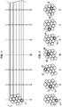
- a bundle 1 of optical fibers comprises N optical fibers 2 (or more simply “fibers” in the following), N being greater than or equal to 3.
- N 12.
- the N optical fibers 2 extend parallel to an axis of the beam 1.
- the optical fibers 2 are arranged to form together a bundle extending around this axis.
- each optical fiber is adjacent to at least one other optical fiber of the bundle.
- the optical fiber 2T is adjacent to two optical fibers; the optical fiber 2W is adjacent to six optical fibers.
- the optical fibers 2 of the bundle have respective axes that do not all pass in one and the same plane. In other words, the fibers are not coplanar.
- the bundle is not a ribbon.
- the beam 1 also comprises N adhesive points 4 whose function is to bind together the optical fibers 2, and thus to ensure that the beam 1 retains its bundle shape, more compact than a ribbon.
- the adhesive spots 4 are formed from resin or glue.
- the N points of adhesive 4 are spaced from each other on the optical fibers 2. They occupy respective different positions in a direction parallel to the axis of the beam.
- two adhesive points 4 having consecutive positions in the direction parallel to the axis of the beam 1 are separated by a distance in this direction which lies in a range of from 0.1 millimeters to 20 centimeters.
- Each point of adhesive 4 touches a set of optical fibers 2 of the bundle.
- the N sets of the bundle respectively affected by the N points of adhesives are different from each other.
- An assembly comprises a plurality of optical fibers of the bundle, in particular two mutually adjacent optical fibers so that the point of adhesive 4 associated with this assembly fixes the optical fibers 2 of the assembly relative to one another. This rule applies to each of the N sets.
- An assembly associated with one of the N adhesive points 4 comprises two, three, four, five, six or seven optical fibers of the bundle.
- optical fibers 2 of this set are not necessarily all mutually adjacent.
- Each set comprises a "central" optical fiber in the sense that this central optical fiber is adjacent to each of the other optical fibers of the assembly.
- the respective central optical fibers of the N sets are all different.
- Each optical fiber 2 of the beam belongs to at least one of the N sets.
- the adhesive point 4 associated with a set extends 360 degrees around a central optical fiber of this set.
- the set of fibers touched by the 4T adhesive dot comprises three optical fibers: the 2T fiber and the two fibers adjacent to the 2T fiber. Any one of these three fibers are adjacent to the other two so that each of them can be considered as a central fiber of the set.
- the 4T adhesive dot extends 360 degrees around the 2T fiber. This point of adhesive also affects the two fibers adjacent to the fiber 2T, so that the point of adhesive 4T makes it possible to fix the three fibers of the associated assembly mutually.
- the assembly touched by the 4W adhesive dot comprises seven optical fibers: the fiber 2W and the six adjacent fibers.
- the 2W optical fiber is a central fiber of the whole.
- the point of adhesive extends 360 degrees around this 2W core fiber.
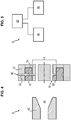
- a device 6 making it possible to obtain a bundle 1 of optical fibers such as that represented on the Figures 1 and 2 comprises a drum 8 and a dispensing element 10.
- the drum 8 has a radially outer surface 12 extending about a central axis.
- the radially outer surface 12 has a shape of revolution about the central axis, for example a right circular cylinder shape.
- the drum 8 also has a front surface 14, and a rear surface 16 opposite the front surface 14.
- the front surface 14 and the rear surface 16 are connected to each other by the radially outer surface 12 and are perpendicular to each other. to the central axis.
- the radially outer surface 12 is in the form of a straight cylinder, the front and rear surfaces are circular.
- the drum 8 defines N through-passages 18. Each passage 18 opens on the one hand into the front surface 14, and on the other hand into the rear surface 16.
- N passages 18 are at a distance from each other. They are for example all parallel to the central axis of the drum 8. The N passages 18 are for example distributed around the central axis in a regular manner, in a circle.
- Each passage 18 of the drum 8 is intended to be traversed by an optical fiber 2.
- Each passage 18 thus has an entrance in the rear face 16 through which an optical fiber 2 can be inserted in the passage 18, and an exit in the face before 14 by which the optical fiber 2 can emerge from the same passage 18.
- the drum 8 further defines N injection channels 20 of adhesive liquid.
- Each injection channel 20 opens on the one hand outside the drum 8 and opens on the other hand in only one of the N passages 18.
- the "associated" injection channel 20 at one of the passages 18 of the drum 8 is the injection channel 20 which opens into this passage 18.
- the injection channels 20 extend for example perpendicularly to the central axis so as to open into the outer surface 12.
- the injection channels 20 extend for example radially to the central axis, perpendicular to the passages 18.
- the device 6 comprises at least one nozzle 22 arranged in a passage 18.
- This nozzle 22 is arranged to allow a 360-degree distribution of adhesive liquid coming from the injection channel 20 associated with this passage 18, around an optical fiber 2 which would be inserted in this passage 18.
- Such a nozzle 22 is known from the state of the art.
- the device 6 may comprise N nozzles 22 of this type which are respectively arranged in the N passages of the drum 8 (the nozzles 22 are not represented on the figure 4 , 6 , 7 , 8 discussed below to improve their readability).
- the dispensing element 10 further defines a liquid adhesive distribution channel 24.
- the dispensing element 10 is movable relative to the drum 8 in N different positions. In each of these positions, only one of the injection channels 20 is connected to the distribution channel 24.
- the N injection channels are arranged to be connected one after the other with the distribution channel 24 by displacement of the element 10 relative to the drum 8 in the N positions.
- the dispensing element 10 is for example rotatably mounted on the drum 8, for example around it.
- the N preceding positions are N different angular positions of the dispensing element 10 relative to the drum 8 around the central axis.
- the dispensing element 10 typically has a ring or crown shape.
- the dispensing element 10 has a radially inner surface 26 and a radially outer surface 28 opposite the radially inner surface 26.
- the radially inner surface 26 is arranged facing the outer surface 12 of the drum 8.
- the radially inner surface 26 is of revolution, or even in the form of a straight cylinder.
- the radially inner surface 26 has a radius substantially equal to the radius of the outer surface 12 of the drum 8, so that the surfaces 12, 26 touch and slide against each other.
- the distribution channel 24 opens into the radially inner surface 26 and into the radially outer surface 28.
- the distribution channel 24 extends for example radially into the distribution element 10, perpendicular to the passages 18.
- the distribution channel 24 opens into the groove.
- the groove 30 is for example circular.
- the device 6 also comprises a supply element 32.
- the supply element 32 is fixed with respect to the drum 8.
- the supply element 32 and the drum 8 are two parts of the same part, this part defining a cavity for receiving the distribution element 10 so that the dispensing element 10 is interposed between the supply element 32 and the drum 8 when it is received in the cavity.
- This cavity is typically annular.
- the supply element 32 defines an adhesive liquid supply channel 34 arranged to be connected to the dispensing channel 24 in adhesive liquid whatever the position of the dispensing element 10 with respect to the drum 8.
- the supply element 32 has a radially inner surface 36 and a radially outer surface 38 opposite the radially inner surface 36.
- the radially inner surface 36 is arranged facing the radially outer surface 28 of the distribution element 10.
- the radially inner surface 36 has a radius substantially equal to the radius of the radially outer surface 28 of the distribution element 10, so that the surfaces 28, 36 touch and slide against each other.
- the feed channel 34 opens on the one hand into the radially inner surface 36 and on the other hand into the radially outer surface 38 into an inlet port 40.
- the distribution channel 24 extends radially, for example, in the supply element 32.
- the inlet port 40 is intended to be connected to a source of adhesive liquid (not shown).
- the feed channel 34 is arranged in such a way that it can be connected to the circular groove 30. As the groove 30 is all around the dispensing element 10, the feed channel can be connected to the groove 30. regardless of the position of the supply element 32 around the distribution element 10.
- the device 6 further comprises a die 42 arranged downstream of the drum 8, so as to receive optical fibers 2 having passed through the N passages of the drum 8.
- the die 42 defines a conduit 44 of suitable shape to bring about a mutual approximation of the fibers received from the N passages.
- This duct 44 is for example flared upstream upstream, so as to bring about a gradual approximation of the fibers between them during their insertion in the die 42.
- Such a die 42 is known from the state of the art.
- the device 6 further comprises displacement means 46 of the dispensing element 10 with respect to the drum 8.
- the device 6 also comprises advancing means 48 for advancing simultaneously N optical fibers in the N passages of the drum 8, towards the die 42.
- the device 6 also comprises a control unit 50 configured to control the displacement means 46 and advancement 48.
- a method of obtaining the beam 1 by means of the device 6 comprises the following steps.
- the N optical fibers are inserted into the N passages 18 of the drum 8, where appropriate using the advancing means 48, by the rear surface 16.
- the N fibers are advanced to reach the corresponding injection channels, as shown in FIG. figure 6 (only two of these fibers 2 are visible on the figure 6 ).
- a first dot of adhesive is deposited on one of the optical fibers (eg 4T adhesive dot on the fiber 2T) as follows.
- the control unit 50 drives the moving means 46 so as to position the dispensing element 10 in a first position among the N positions discussed above.
- the distribution channel 24 is connected to the injection channel 20 opening into the passage in which the first fiber 2T is located.
- the distribution channel 24 is at this stage connected to none of the other N-1 injection channels 20.
- Adhesive liquid A (resin or glue for example) is taken from the source so that it enters the supply element 32 through its inlet.
- the adhesive liquid A passes through the supply channel 32, and enters the groove 30. It may be that in the current position of the distribution element 10, the supply and distribution channels are not directly opposite. Nevertheless, the adhesive liquid A still reaches the distribution channel 24 after having circulated in the circular groove extending around the central axis of the drum 8.
- the adhesive liquid then enters the injection channel 20 connected to the channel 24, and reaches the nozzle surrounding the first fiber 2T.
- the nozzle deposits the adhesive liquid A 360 degrees around the fiber 2T, so as to form the first point of 4T adhesive, in accordance with figure 7 .
- the first point of adhesive extends only over a portion of the fiber having a limited length.
- the control unit 50 also controls the advancing means 48 so as to advance the optical fibers 2 simultaneously by a distance ranging from 0.1 millimeters to 20 centimeters.
- a second point of adhesive (the adhesive point 4U) is deposited on a second of the optical fibers 2 (the fiber 2U) by repeating the above steps.
- the control unit 50 drives the displacement means 46 so as to position the dispensing element 10 in a second position among the N positions discussed previously.
- the distribution channel 24 is connected to the injection channel 20 opening into the passage in which the second fiber 2V is located.
- the distribution channel 24 is at this stage connected to none of the other N-1 injection channels 20.
- the adhesive liquid injection step A described above is repeated, so that adhesive liquid A entering through the inlet port 40 is deposited 360 degrees around the fiber 2U, so as to form the second point d 4U adhesive.
- control unit 50 can drive the advancing means 48 of the fibers 2 and the moving means 46 of the dispensing element 10 of different ways.
- the control unit 50 can drive the advancing means 48 step by step, the selected pitch corresponding to the distance chosen between two consecutive adhesive points along the beam 1. In this case, an adhesive point 4 can be applied to one of the fibers 2 while the latter is stationary relative to the drum 8.
- the control unit 50 can drive the advancing means 48 so that the optical fibers 2 are advanced at a constant speed and in a continuous manner, that is to say without stopping relative to the drum 8.
- the control unit 50 controls a displacement of the dispensing element 10 relative to the drum 8 concomitantly the advance of the optical fibers 2 in the N passages 18 of the drum 8.
- control unit 50 can control the displacement means 46 of the dispensing element 10 in steps, the chosen pitch corresponding to an angular difference between two adjacent injection channels 20 of the drum 8.
- an adhesive dot 4 can be applied to one of the fibers 2 while the dispensing element 10 is stationary relative to the drum 8.
- control unit 50 can drive the displacement means 46 so that the dispensing element 10 is moved at constant speed and in a continuous manner, that is to say without stopping relative to the drum 8.
- the quantity of adhesive liquid transmitted in any of the injection channels 20 then depends on the duration during which this injection channel 20 remains connected to the distribution channel 24.
- the optical fibers 2 are advanced by the advancing means 48 to leave the N passages 18 by the front face 14. At this stage, the N optical fibers 2 are at a distance from each other because the N passages 18 formed in the drum 8 are at a distance from each other.
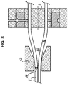
- the optical fibers 2 are advanced so as to penetrate into the conduit 44 of the die 42 arranged downstream of the drum 8.
- the die 42 naturally brings the fibers 2 closer together so that the fibers 2 are reorganized into a compact bundle in which optical fibers 2 are non-coplanar, as shown in FIG. Figures 1 and 2 .
- each point of adhesive 4 initially deposited on an optical fiber 2 comes into contact with at least one other fiber 2 which is adjacent thereto at the end of this reorganization.
- the central optical fiber 2 of each set of fibers touched by a given dot of adhesive is the fiber on which this point of adhesive was initially deposited, before entering the die 42.
- optical fibers 2 of the same set are permanently bonded together once the adhesive liquid A used to form the N points of adhesive 4 has dried.
- the adhesive liquid A used is thermoplastic
- a UV crosslinking step is carried out on the adhesive spots so that they perform their mutual fixing function of adjacent optical fibers 2 in the bundle formed in the die 42.
- figure 8 there is shown in figure 8 the fiber 2T whose adhesive point 4T comes to touch another optical fiber 2 during the insertion of these fibers in the die 42.
- this figure is a simplified view because only represents two optical fibers 2; in fact, the N fibers enter the die 42 and are mutually close together.
- the beam 1 represented on the Figures 1 and 2 is obtained at the exit of the die 42.
- the optical fiber bundle 1 obtained has the advantages of a flexible and cylindrical micromodule comprising a set of optical fibers, without the use of thermoplastic skins or tubes for assembling the optical fibers.
- This beam is also easy to insert into an optical cable structure of cylindrical section by simple guiding in the central cavity of such an optical cable.
- an adhesive point 4 has been deposited on a 360 degree optical fiber 2 allows this fiber to be bonded by this point of adhesive to a larger number of adjacent optical fibers, which reinforces the cohesion of the beam 1 obtained. It is nevertheless possible to deposit on at least one of the fibers 2 adhesive liquid A extending only over a portion of the circumference of a fiber, that is to say on an angular sector of less than 360 degrees.
- the supply element 32 also has the advantage of making the device 6 more convenient to use. Indeed, it could be envisaged to directly connect the distribution channel 24 to a source of adhesive liquid, for example via a flexible cable. However, this flexible cable should necessarily be moved during the displacement of the dispensing element 10 relative to the drum 8. This disadvantage is overcome by the supply element 32 since it remains fixed relative to the drum 8; such a flexible cable connected to the inlet port can thus remain stationary during the displacement of the distribution element 10.
- the groove 30 may further be variant.
- the groove is formed in the radially inner surface of the supply element 32 and not in the radially outer surface of the dispensing element 10.
- the groove is partially formed in the radially outer surface of the dispensing element 10, and partially in the radially inner surface of the supply element 32.
- the N points of adhesive 4 applied can also be colored in different colors, for the purpose of identifying an optical fiber 2 in the beam 1.
Landscapes
- Physics & Mathematics (AREA)
- General Physics & Mathematics (AREA)
- Optics & Photonics (AREA)
- Mechanical Coupling Of Light Guides (AREA)
- Optical Fibers, Optical Fiber Cores, And Optical Fiber Bundles (AREA)
Applications Claiming Priority (1)
| Application Number | Priority Date | Filing Date | Title |
|---|---|---|---|
| FR1853213A FR3080192B1 (fr) | 2018-04-12 | 2018-04-12 | Faisceau de fibres optiques liees entre elles avec de l'adhesif, procede et dispositif d'obtention d'un tel faisceau |
Publications (2)
| Publication Number | Publication Date |
|---|---|
| EP3553576A1 true EP3553576A1 (de) | 2019-10-16 |
| EP3553576B1 EP3553576B1 (de) | 2021-04-07 |
Family
ID=63014697
Family Applications (1)
| Application Number | Title | Priority Date | Filing Date |
|---|---|---|---|
| EP19168756.5A Active EP3553576B1 (de) | 2018-04-12 | 2019-04-11 | Bündel aus optischen fasern, die durch kleber miteinander verbunden sind, verfahren und vorrichtung zur herstellung eines solchen bündels |
Country Status (2)
| Country | Link |
|---|---|
| EP (1) | EP3553576B1 (de) |
| FR (1) | FR3080192B1 (de) |
Citations (3)
| Publication number | Priority date | Publication date | Assignee | Title |
|---|---|---|---|---|
| JPH10160987A (ja) * | 1996-12-02 | 1998-06-19 | Sumitomo Electric Ind Ltd | 光ファイバユニットおよび光ケーブル |
| EP3168665A1 (de) * | 2015-05-21 | 2017-05-17 | Fujikura Ltd. | Verfahren zur herstellung einer optischen fasereinheit und herstellungsvorrichtung |
| JP2017173517A (ja) * | 2016-03-23 | 2017-09-28 | 住友電気工業株式会社 | 光ファイバテープ心線の製造方法および製造装置 |
-
2018
- 2018-04-12 FR FR1853213A patent/FR3080192B1/fr active Active
-
2019
- 2019-04-11 EP EP19168756.5A patent/EP3553576B1/de active Active
Patent Citations (3)
| Publication number | Priority date | Publication date | Assignee | Title |
|---|---|---|---|---|
| JPH10160987A (ja) * | 1996-12-02 | 1998-06-19 | Sumitomo Electric Ind Ltd | 光ファイバユニットおよび光ケーブル |
| EP3168665A1 (de) * | 2015-05-21 | 2017-05-17 | Fujikura Ltd. | Verfahren zur herstellung einer optischen fasereinheit und herstellungsvorrichtung |
| JP2017173517A (ja) * | 2016-03-23 | 2017-09-28 | 住友電気工業株式会社 | 光ファイバテープ心線の製造方法および製造装置 |
Also Published As
| Publication number | Publication date |
|---|---|
| FR3080192A1 (fr) | 2019-10-18 |
| FR3080192B1 (fr) | 2020-03-27 |
| EP3553576B1 (de) | 2021-04-07 |
Similar Documents
| Publication | Publication Date | Title |
|---|---|---|
| EP0733925B1 (de) | Verfahren zur Bildung eines Mantels eines LWL-Moduls und faseroptisches Kabel bestehend aus LWL-Modulen, die einen solchen Mantel aufweisen | |
| FR2748576A1 (fr) | Dispositif pour lover des rubans ou des micro-gaines de fibres optiques, et leurs epissures ou coupleurs de raccordement | |
| FR2727212A1 (fr) | Procede de fabrication d'un module cylindrique de fibres optiques | |
| CH627858A5 (fr) | Dispositif de raccordement global en bout de deux groupes de sept fibres optiques. | |
| EP0562934B1 (de) | Ein Dornführungsgegenstück enthaltende Giessvorrichtung zum Giessen von faseroptischen Steckerstiften und mit Hilfe dieser Vorrichtung gegossener Steckerstift | |
| EP0058594B1 (de) | Gerät zum gleichzeitigen Einlegen von optischen Fasern in einen strukturierten zylindrischen Tragekörper und Kabelherstellungsvorrichtung mit einem derartigen Gerät | |
| EP0174215B1 (de) | Vorrichtung zum Einführen von optischen Fibern | |
| JP5759795B2 (ja) | 光ファイバテープ心線の製造方法 | |
| FR2499723A1 (fr) | Distributeur optique | |
| EP3553576B1 (de) | Bündel aus optischen fasern, die durch kleber miteinander verbunden sind, verfahren und vorrichtung zur herstellung eines solchen bündels | |
| FR2698180A1 (fr) | Porte-épissure de fibres optiques pour cordons de fibres optiques en forme de rubans. | |
| EP0036369B1 (de) | Verfahren und Vorrichtung zum Verbinden faseroptischer Kabel auf dem Arbeitsplatz | |
| EP0712018A1 (de) | Kassette zur Unterbringung und zum Schutz eine optischen Faser und Stapelvorrichtung für diese Kassetten | |
| EP0096608B1 (de) | Faseroptischer Kollimator, Anwendung zur Realisierung optischer Schaltervorrichtungen | |
| EP3729156A1 (de) | Optisches kabel mit ripcords | |
| EP0535199B1 (de) | Verfahren und einrichtung zum kontinuierlichen herstellen eines flachkabels, insbesondere ein fiberoptisches kabel | |
| FR3028679A1 (fr) | Dispositif et procede de collage d'un cable sur une structure | |
| WO1996025680A1 (fr) | Cassette de raccordement de fibres optiques | |
| FR2745393A1 (fr) | Dispositif de support d'epissures, notamment pour fibres ou modules optiques | |
| EP3288880B1 (de) | Vorrichtung und verfahren zum einsetzen einer optischen faser in eine spule | |
| FR2564987A1 (fr) | Ligne de fabrication d'un element de cable a fibres optiques | |
| FR2681149A1 (fr) | Dispositif d'insertion de rubans a fibres optiques dans les rainures helicouidales d'un jonc rainure. | |
| FR2564989A1 (fr) | Dispositif de rangement de cables a fibres optiques | |
| FR2561788A1 (fr) | Cassettes pour fibres optiques et boite de raccordement utilisant de telles cassettes | |
| FR2749406A1 (fr) | Dispositif de transition de pas, notamment pour fibres optiques |
Legal Events
| Date | Code | Title | Description |
|---|---|---|---|
| PUAI | Public reference made under article 153(3) epc to a published international application that has entered the european phase |
Free format text: ORIGINAL CODE: 0009012 |
|
| STAA | Information on the status of an ep patent application or granted ep patent |
Free format text: STATUS: THE APPLICATION HAS BEEN PUBLISHED |
|
| AK | Designated contracting states |
Kind code of ref document: A1 Designated state(s): AL AT BE BG CH CY CZ DE DK EE ES FI FR GB GR HR HU IE IS IT LI LT LU LV MC MK MT NL NO PL PT RO RS SE SI SK SM TR |
|
| AX | Request for extension of the european patent |
Extension state: BA ME |
|
| STAA | Information on the status of an ep patent application or granted ep patent |
Free format text: STATUS: REQUEST FOR EXAMINATION WAS MADE |
|
| 17P | Request for examination filed |
Effective date: 20191212 |
|
| RAP1 | Party data changed (applicant data changed or rights of an application transferred) |
Owner name: ACOME |
|
| RBV | Designated contracting states (corrected) |
Designated state(s): AL AT BE BG CH CY CZ DE DK EE ES FI FR GB GR HR HU IE IS IT LI LT LU LV MC MK MT NL NO PL PT RO RS SE SI SK SM TR |
|
| RIC1 | Information provided on ipc code assigned before grant |
Ipc: G02B 6/06 20060101ALI20201021BHEP Ipc: G02B 6/36 20060101AFI20201021BHEP Ipc: G02B 6/44 20060101ALI20201021BHEP |
|
| GRAP | Despatch of communication of intention to grant a patent |
Free format text: ORIGINAL CODE: EPIDOSNIGR1 |
|
| STAA | Information on the status of an ep patent application or granted ep patent |
Free format text: STATUS: GRANT OF PATENT IS INTENDED |
|
| INTG | Intention to grant announced |
Effective date: 20201127 |
|
| GRAS | Grant fee paid |
Free format text: ORIGINAL CODE: EPIDOSNIGR3 |
|
| GRAA | (expected) grant |
Free format text: ORIGINAL CODE: 0009210 |
|
| STAA | Information on the status of an ep patent application or granted ep patent |
Free format text: STATUS: THE PATENT HAS BEEN GRANTED |
|
| AK | Designated contracting states |
Kind code of ref document: B1 Designated state(s): AL AT BE BG CH CY CZ DE DK EE ES FI FR GB GR HR HU IE IS IT LI LT LU LV MC MK MT NL NO PL PT RO RS SE SI SK SM TR |
|
| REG | Reference to a national code |
Ref country code: GB Ref legal event code: FG4D Free format text: NOT ENGLISH |
|
| REG | Reference to a national code |
Ref country code: AT Ref legal event code: REF Ref document number: 1380431 Country of ref document: AT Kind code of ref document: T Effective date: 20210415 Ref country code: CH Ref legal event code: EP |
|
| REG | Reference to a national code |
Ref country code: DE Ref legal event code: R096 Ref document number: 602019003684 Country of ref document: DE |
|
| REG | Reference to a national code |
Ref country code: IE Ref legal event code: FG4D Free format text: LANGUAGE OF EP DOCUMENT: FRENCH |
|
| REG | Reference to a national code |
Ref country code: LT Ref legal event code: MG9D |
|
| REG | Reference to a national code |
Ref country code: NL Ref legal event code: MP Effective date: 20210407 Ref country code: AT Ref legal event code: MK05 Ref document number: 1380431 Country of ref document: AT Kind code of ref document: T Effective date: 20210407 |
|
| PG25 | Lapsed in a contracting state [announced via postgrant information from national office to epo] |
Ref country code: LT Free format text: LAPSE BECAUSE OF FAILURE TO SUBMIT A TRANSLATION OF THE DESCRIPTION OR TO PAY THE FEE WITHIN THE PRESCRIBED TIME-LIMIT Effective date: 20210407 Ref country code: HR Free format text: LAPSE BECAUSE OF FAILURE TO SUBMIT A TRANSLATION OF THE DESCRIPTION OR TO PAY THE FEE WITHIN THE PRESCRIBED TIME-LIMIT Effective date: 20210407 Ref country code: FI Free format text: LAPSE BECAUSE OF FAILURE TO SUBMIT A TRANSLATION OF THE DESCRIPTION OR TO PAY THE FEE WITHIN THE PRESCRIBED TIME-LIMIT Effective date: 20210407 Ref country code: NL Free format text: LAPSE BECAUSE OF FAILURE TO SUBMIT A TRANSLATION OF THE DESCRIPTION OR TO PAY THE FEE WITHIN THE PRESCRIBED TIME-LIMIT Effective date: 20210407 Ref country code: BG Free format text: LAPSE BECAUSE OF FAILURE TO SUBMIT A TRANSLATION OF THE DESCRIPTION OR TO PAY THE FEE WITHIN THE PRESCRIBED TIME-LIMIT Effective date: 20210707 Ref country code: AT Free format text: LAPSE BECAUSE OF FAILURE TO SUBMIT A TRANSLATION OF THE DESCRIPTION OR TO PAY THE FEE WITHIN THE PRESCRIBED TIME-LIMIT Effective date: 20210407 |
|
| PG25 | Lapsed in a contracting state [announced via postgrant information from national office to epo] |
Ref country code: GR Free format text: LAPSE BECAUSE OF FAILURE TO SUBMIT A TRANSLATION OF THE DESCRIPTION OR TO PAY THE FEE WITHIN THE PRESCRIBED TIME-LIMIT Effective date: 20210708 Ref country code: IS Free format text: LAPSE BECAUSE OF FAILURE TO SUBMIT A TRANSLATION OF THE DESCRIPTION OR TO PAY THE FEE WITHIN THE PRESCRIBED TIME-LIMIT Effective date: 20210807 Ref country code: SE Free format text: LAPSE BECAUSE OF FAILURE TO SUBMIT A TRANSLATION OF THE DESCRIPTION OR TO PAY THE FEE WITHIN THE PRESCRIBED TIME-LIMIT Effective date: 20210407 Ref country code: RS Free format text: LAPSE BECAUSE OF FAILURE TO SUBMIT A TRANSLATION OF THE DESCRIPTION OR TO PAY THE FEE WITHIN THE PRESCRIBED TIME-LIMIT Effective date: 20210407 Ref country code: PT Free format text: LAPSE BECAUSE OF FAILURE TO SUBMIT A TRANSLATION OF THE DESCRIPTION OR TO PAY THE FEE WITHIN THE PRESCRIBED TIME-LIMIT Effective date: 20210809 Ref country code: LV Free format text: LAPSE BECAUSE OF FAILURE TO SUBMIT A TRANSLATION OF THE DESCRIPTION OR TO PAY THE FEE WITHIN THE PRESCRIBED TIME-LIMIT Effective date: 20210407 Ref country code: PL Free format text: LAPSE BECAUSE OF FAILURE TO SUBMIT A TRANSLATION OF THE DESCRIPTION OR TO PAY THE FEE WITHIN THE PRESCRIBED TIME-LIMIT Effective date: 20210407 Ref country code: NO Free format text: LAPSE BECAUSE OF FAILURE TO SUBMIT A TRANSLATION OF THE DESCRIPTION OR TO PAY THE FEE WITHIN THE PRESCRIBED TIME-LIMIT Effective date: 20210707 |
|
| PG25 | Lapsed in a contracting state [announced via postgrant information from national office to epo] |
Ref country code: LU Free format text: LAPSE BECAUSE OF NON-PAYMENT OF DUE FEES Effective date: 20210411 |
|
| REG | Reference to a national code |
Ref country code: DE Ref legal event code: R097 Ref document number: 602019003684 Country of ref document: DE |
|
| REG | Reference to a national code |
Ref country code: BE Ref legal event code: MM Effective date: 20210430 |
|
| PG25 | Lapsed in a contracting state [announced via postgrant information from national office to epo] |
Ref country code: CZ Free format text: LAPSE BECAUSE OF FAILURE TO SUBMIT A TRANSLATION OF THE DESCRIPTION OR TO PAY THE FEE WITHIN THE PRESCRIBED TIME-LIMIT Effective date: 20210407 Ref country code: DK Free format text: LAPSE BECAUSE OF FAILURE TO SUBMIT A TRANSLATION OF THE DESCRIPTION OR TO PAY THE FEE WITHIN THE PRESCRIBED TIME-LIMIT Effective date: 20210407 Ref country code: RO Free format text: LAPSE BECAUSE OF FAILURE TO SUBMIT A TRANSLATION OF THE DESCRIPTION OR TO PAY THE FEE WITHIN THE PRESCRIBED TIME-LIMIT Effective date: 20210407 Ref country code: MC Free format text: LAPSE BECAUSE OF FAILURE TO SUBMIT A TRANSLATION OF THE DESCRIPTION OR TO PAY THE FEE WITHIN THE PRESCRIBED TIME-LIMIT Effective date: 20210407 Ref country code: SM Free format text: LAPSE BECAUSE OF FAILURE TO SUBMIT A TRANSLATION OF THE DESCRIPTION OR TO PAY THE FEE WITHIN THE PRESCRIBED TIME-LIMIT Effective date: 20210407 Ref country code: SK Free format text: LAPSE BECAUSE OF FAILURE TO SUBMIT A TRANSLATION OF THE DESCRIPTION OR TO PAY THE FEE WITHIN THE PRESCRIBED TIME-LIMIT Effective date: 20210407 Ref country code: ES Free format text: LAPSE BECAUSE OF FAILURE TO SUBMIT A TRANSLATION OF THE DESCRIPTION OR TO PAY THE FEE WITHIN THE PRESCRIBED TIME-LIMIT Effective date: 20210407 Ref country code: EE Free format text: LAPSE BECAUSE OF FAILURE TO SUBMIT A TRANSLATION OF THE DESCRIPTION OR TO PAY THE FEE WITHIN THE PRESCRIBED TIME-LIMIT Effective date: 20210407 |
|
| PLBE | No opposition filed within time limit |
Free format text: ORIGINAL CODE: 0009261 |
|
| STAA | Information on the status of an ep patent application or granted ep patent |
Free format text: STATUS: NO OPPOSITION FILED WITHIN TIME LIMIT |
|
| 26N | No opposition filed |
Effective date: 20220110 |
|
| PG25 | Lapsed in a contracting state [announced via postgrant information from national office to epo] |
Ref country code: IE Free format text: LAPSE BECAUSE OF NON-PAYMENT OF DUE FEES Effective date: 20210411 |
|
| PG25 | Lapsed in a contracting state [announced via postgrant information from national office to epo] |
Ref country code: IS Free format text: LAPSE BECAUSE OF FAILURE TO SUBMIT A TRANSLATION OF THE DESCRIPTION OR TO PAY THE FEE WITHIN THE PRESCRIBED TIME-LIMIT Effective date: 20210807 Ref country code: AL Free format text: LAPSE BECAUSE OF FAILURE TO SUBMIT A TRANSLATION OF THE DESCRIPTION OR TO PAY THE FEE WITHIN THE PRESCRIBED TIME-LIMIT Effective date: 20210407 |
|
| PG25 | Lapsed in a contracting state [announced via postgrant information from national office to epo] |
Ref country code: IT Free format text: LAPSE BECAUSE OF FAILURE TO SUBMIT A TRANSLATION OF THE DESCRIPTION OR TO PAY THE FEE WITHIN THE PRESCRIBED TIME-LIMIT Effective date: 20210407 Ref country code: BE Free format text: LAPSE BECAUSE OF NON-PAYMENT OF DUE FEES Effective date: 20210430 |
|
| REG | Reference to a national code |
Ref country code: CH Ref legal event code: PL |
|
| PG25 | Lapsed in a contracting state [announced via postgrant information from national office to epo] |
Ref country code: LI Free format text: LAPSE BECAUSE OF NON-PAYMENT OF DUE FEES Effective date: 20220430 Ref country code: CH Free format text: LAPSE BECAUSE OF NON-PAYMENT OF DUE FEES Effective date: 20220430 |
|
| P01 | Opt-out of the competence of the unified patent court (upc) registered |
Effective date: 20230427 |
|
| PG25 | Lapsed in a contracting state [announced via postgrant information from national office to epo] |
Ref country code: CY Free format text: LAPSE BECAUSE OF FAILURE TO SUBMIT A TRANSLATION OF THE DESCRIPTION OR TO PAY THE FEE WITHIN THE PRESCRIBED TIME-LIMIT Effective date: 20210407 |
|
| PG25 | Lapsed in a contracting state [announced via postgrant information from national office to epo] |
Ref country code: HU Free format text: LAPSE BECAUSE OF FAILURE TO SUBMIT A TRANSLATION OF THE DESCRIPTION OR TO PAY THE FEE WITHIN THE PRESCRIBED TIME-LIMIT; INVALID AB INITIO Effective date: 20190411 |
|
| PG25 | Lapsed in a contracting state [announced via postgrant information from national office to epo] |
Ref country code: MK Free format text: LAPSE BECAUSE OF FAILURE TO SUBMIT A TRANSLATION OF THE DESCRIPTION OR TO PAY THE FEE WITHIN THE PRESCRIBED TIME-LIMIT Effective date: 20210407 |
|
| PG25 | Lapsed in a contracting state [announced via postgrant information from national office to epo] |
Ref country code: MT Free format text: LAPSE BECAUSE OF FAILURE TO SUBMIT A TRANSLATION OF THE DESCRIPTION OR TO PAY THE FEE WITHIN THE PRESCRIBED TIME-LIMIT Effective date: 20210407 |
|
| PGFP | Annual fee paid to national office [announced via postgrant information from national office to epo] |
Ref country code: DE Payment date: 20250411 Year of fee payment: 7 |
|
| PGFP | Annual fee paid to national office [announced via postgrant information from national office to epo] |
Ref country code: GB Payment date: 20250417 Year of fee payment: 7 |
|
| PGFP | Annual fee paid to national office [announced via postgrant information from national office to epo] |
Ref country code: FR Payment date: 20250429 Year of fee payment: 7 |
|
| PG25 | Lapsed in a contracting state [announced via postgrant information from national office to epo] |
Ref country code: TR Free format text: LAPSE BECAUSE OF FAILURE TO SUBMIT A TRANSLATION OF THE DESCRIPTION OR TO PAY THE FEE WITHIN THE PRESCRIBED TIME-LIMIT Effective date: 20210407 |