EP3553570A1 - Millimeterwellenabtastendes bildgebungssystem zur frei- und grossraumüberwachung mit sicherheitsinspektionsverfahren - Google Patents
Millimeterwellenabtastendes bildgebungssystem zur frei- und grossraumüberwachung mit sicherheitsinspektionsverfahren Download PDFInfo
- Publication number
- EP3553570A1 EP3553570A1 EP19168495.0A EP19168495A EP3553570A1 EP 3553570 A1 EP3553570 A1 EP 3553570A1 EP 19168495 A EP19168495 A EP 19168495A EP 3553570 A1 EP3553570 A1 EP 3553570A1
- Authority
- EP
- European Patent Office
- Prior art keywords
- millimeter wave
- scanning imaging
- scene
- imaging system
- wave scanning
- Prior art date
- Legal status (The legal status is an assumption and is not a legal conclusion. Google has not performed a legal analysis and makes no representation as to the accuracy of the status listed.)
- Granted
Links
Images

Classifications
-
- G—PHYSICS
- G01—MEASURING; TESTING
- G01V—GEOPHYSICS; GRAVITATIONAL MEASUREMENTS; DETECTING MASSES OR OBJECTS; TAGS
- G01V8/00—Prospecting or detecting by optical means
- G01V8/005—Prospecting or detecting by optical means operating with millimetre waves, e.g. measuring the black losey radiation
-
- G—PHYSICS
- G01—MEASURING; TESTING
- G01S—RADIO DIRECTION-FINDING; RADIO NAVIGATION; DETERMINING DISTANCE OR VELOCITY BY USE OF RADIO WAVES; LOCATING OR PRESENCE-DETECTING BY USE OF THE REFLECTION OR RERADIATION OF RADIO WAVES; ANALOGOUS ARRANGEMENTS USING OTHER WAVES
- G01S13/00—Systems using the reflection or reradiation of radio waves, e.g. radar systems; Analogous systems using reflection or reradiation of waves whose nature or wavelength is irrelevant or unspecified
- G01S13/88—Radar or analogous systems specially adapted for specific applications
- G01S13/89—Radar or analogous systems specially adapted for specific applications for mapping or imaging
Definitions
- Embodiments of the present disclosure generally relate to the field of security inspection, and particularly, to a scene monitoring type millimeter wave scanning imaging system and a security inspection method by using the same.
- Millimeter wave detection imaging technology has advantages such as non-ionizing radiation, abilities of penetrating clothing over a human body and identifying various metal and non-metallic contrabands, and the like. With the development of millimeter wave technology and the reduction of device cost in the past decade, it is gradually attracting attention in human security inspection. Millimeter wave detection imaging technology is mainly divided into a passive millimeter wave imaging technology and an active millimeter wave imaging technology, while the active millimeter wave imaging technology is mainly based on holographic imaging technology. Compared with the passive imaging technology, an active millimeter wave image is clear, has a high resolution, and can meet requirement of human security inspection.
- the existing active millimeter wave security imaging system mainly includes a cylindrical scanning system, a plane scanning system and an area array scanning system. Due to the limitation of imaging time, an inspected person needs to stand in front of the human security inspection system for a certain period of time to complete the inspection, thus greatly limiting the throughout rate of the security inspection. In the actual security inspection, the existing equipment can only support inspection of one target. If it is desired to inspect a plurality of human bodies at the same time, many equipments are needed, and thus the cost and occupying space will be greatly increased.
- the present disclosure is made to at least partly solve or alleviate at least one aspect of the above mentioned and other disadvantages or problems in prior arts.
- a scene monitoring type millimeter wave scanning imaging system including a plurality of millimeter wave scanning imaging devices adapted to be positioned in a security inspection scene, such that the plurality of millimeter wave scanning imaging devices are arranged to be oriented towards different orientations respectively so as to scan and image objects to be inspected located within different inspection areas of the security inspection scene with millimeter waves and to provide scan data for the objects.
- the plurality of millimeter wave scanning imaging devices are arranged in a columnar arrangement having a plurality of side faces, each of which is defined by a corresponding one of the plurality of millimeter wave scanning imaging devices so as to face a corresponding one of the orientations in the security inspection scene.
- a cross section of the columnar arrangement has a closed polygonal shape having sides each defined by a corresponding one of the plurality of millimeter wave scanning imaging devices.
- the closed polygonal shape includes a triangular shape, a quadrilateral shape, a pentagonal shape or a hexagonal shape.
- two adjacent ones of the side faces of the columnar arrangement form an angle greater than zero degree and less than 180 degrees.
- the scene monitoring type millimeter wave scanning imaging system further includes an optical camera configured to capture an optical image of an object to be inspected entering the security inspection scene, for determining whether or not the object to be inspected reaches one of the inspection areas towards which a corresponding one of the plurality of millimeter wave scanning imaging devices faces before the corresponding one of the millimeter wave scanning imaging devices is started-up for scanning imaging.
- the scene monitoring type millimeter wave scanning imaging system is provided with or includes a plurality of said optical cameras, each of which is associated with a corresponding one of the plurality of millimeter wave scanning imaging devices so as to capture the optical image of the object to be inspected entering one of the inspection areas towards which the associated one of the millimeter wave scanning imaging devices faces.
- each of the plurality of millimeter wave scanning imaging devices includes a millimeter wave transceiver antenna array, the millimeter wave transceiver antenna array including a mesh-shaped transceiver antenna array consisting of a plurality of sub-array units, each of the plurality of sub-array units includes a transmitting antenna linear array and a receiving antenna linear array, the transmitting antenna linear array includes a plurality of millimeter wave transmitting antennas arranged linearly, and the receiving antenna linear array includes a plurality of millimeter wave receiving antennas arranged linearly.
- each of the plurality of sub-array units has a rectangular shape and includes two said transmitting antenna linear arrays arranged respectively along a pair of sides of the rectangular shape facing each other and two said receiving antenna linear arrays arranged respectively along another pair of sides of the rectangular shape facing each other; and two adjacent ones of the plurality of sub-array units share one said transmitting antenna linear array or one said receiving antenna linear array.
- each of the plurality of sub-array units includes one said transmitting antenna linear array and one said receiving antenna linear array crossing each other to form a crisscross shape.
- At least one millimeter wave transceiver antenna array has a plane or arc profile.
- each of the plurality of millimeter wave scanning imaging devices further includes a first millimeter wave source, a second millimeter wave source, a mixer, a switch matrix, a transmitter module and a receiver module;
- the first millimeter wave source is configured as a transmitting source for generating a first millimeter wave signal;
- the second millimeter wave source is configured as a reference source for generating a second millimeter wave signal;
- the mixer is configured to mix in frequency the second millimeter wave signal generated by the second millimeter wave source with the first millimeter wave signal generated by the first millimeter wave source so as to form a frequency mixed signal as a reference signal;
- the switch matrix is connected between the first millimeter wave source and the transmitter module, and is configured to control switching of on-off states of the millimeter wave transmitting antennas and the millimeter wave receiving antennas such that in response to one millimeter wave transmitting antenna of the plurality millimeter wave transmitting antennas transmitting a millimeter wave signal to the objects
- the scene monitoring type millimeter wave scanning imaging system further includes: a data processing device electrically connected in a wireless way or in a wired way with one or more of the plurality of millimeter wave scanning imaging devices so as to receive the scan data obtained by scanning the objects to be inspected with a millimeter wave by the one or more millimeter wave scanning imaging devices; and a display device connected with the data processing device so as to receive the scan data and to display a millimeter wave image corresponding to the scan data.
- an embodiment of the present disclosure further provides a security inspection method, including scanning and imaging, by using the scene monitoring type millimeter wave scanning imaging system as described in any of embodiments of the present disclosure, objects to be inspected located within different inspection areas of a security inspection scene, with millimeter waves.
- the scanning and imaging, by using the scene monitoring type millimeter wave scanning imaging system, objects to be inspected located within different inspection areas of a security inspection scene, with millimeter waves includes: determining whether an object to be inspected enters one of the inspection areas of the security inspection scene; and after determining an object to be inspected has entered one of the inspection areas of the security inspection scene, scanning and imaging the object with millimeter waves by using a corresponding one of the plurality of millimeter wave scanning imaging devices facing towards the one of the inspection areas.
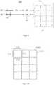
- FIG. 1 schematically shows an arrangement of a scene monitoring type millimeter wave scanning imaging system according to an exemplary embodiment of the present disclosure.
- the millimeter wave scanning imaging system may be applied in active millimeter wave security inspection.
- a scene monitoring type millimeter wave scanning imaging system 10 includes a plurality of millimeter wave scanning imaging devices 100, which are adapted to be positioned in a security inspection scene or in a public place, and arranged to be oriented towards different orientations respectively so as to perform millimeter wave scanning imaging operations on objects 1 to be inspected (for example, passers-by or persons to be inspected) located within different inspection areas or ranges of the security inspection scene or public place and to provide scan data with respect to the objects.
- millimeter wave scanning imaging devices are oriented to different orientations respectively and perform millimeter wave scanning imaging operations on different objects to be inspected entering different inspection areas or ranges of the security inspection scene or public place simultaneously or directionally, for determining whether or not the objects to be inspected have or carry dangerous or prohibited items, thereby enabling full-orientation security monitoring of the entire security inspection scene or public place. It is helpful to improve the throughput rate of the security inspection system, especially in densely populated areas such as airports and stations. It can allow persons to stay for a shorter period of time when passing the security inspection system, and if necessary, suspicious persons may be intercepted and specifically inspected through a remote terminal located at the security exit.
- the scene monitoring type millimeter wave scanning imaging system 10 may further include a data processing device 200 and a display device 300, the data processing device 200 is electrically connected in a in a wireless way or in a wired way with one or more plurality of millimeter wave scanning imaging devices 100 so as to receive the scan data obtained by scanning the objects 1 to be inspected with a millimeter wave by using the millimeter wave scanning imaging devices 100, and the display device 300 is electrically connected in a wireless way or in a wired way with the data processing device 200 so as to receive the scan data and to display a millimeter wave image corresponding to the scan data, for example, a holographic image of the inspected object.
- the data processing device 200 is electrically connected in a in a wireless way or in a wired way with one or more plurality of millimeter wave scanning imaging devices 100 so as to receive the scan data obtained by scanning the objects 1 to be inspected with a millimeter wave by using the millimeter wave scanning imaging devices 100
- the display device 300 is electrically
- the data processing device 200 can receive the data (for example, holographic data) obtained through scanning and perform image reconstruction.
- the data processing device may include a personal computer (PC), a server, or a workstation, etc.
- the data processing device may include a processor and a memory.
- the processor may be electrically connected to the millimeter wave scanning imaging device to receive and process the scan data.
- the memory may be electrically connected to the processor and store instructions therein that, when being executed by the processor, cause the processor to perform the image reconstruction, or control the millimeter wave scanning imaging device to scan the object to be inspected.
- the display device can also display information about the millimeter wave scanning imaging system, for example status information, imaging results, alarm information and the like.
- a plurality of millimeter wave scanning imaging devices 100 may be arranged (for example, spliced or otherwise connected) into a columnar arrangement having a plurality of side faces (for example, vertical side faces), each of which is defined by one corresponding millimeter wave scanning imaging device 100 or includes an outer contour or surface of the corresponding millimeter wave scanning imaging device 100 so as to face a corresponding orientation in the security inspection scene.
- the columnar arrangement can be placed in a security inspection scene or an open area such as a central area of a public place.
- the persons to be inspected pass by the columnar arrangement from different orientations, the persons can be scanned and imaged by the columnar arrangement, thereby eliminating the need to move the millimeter wave scanning imaging device or not requiring the persons to be inspected to enter a security inspection system set up at a specific security inspection location (e.g., an entrance to a security inspection scene or public place, a special security inspection room, etc.) for inspection.
- a specific security inspection location e.g., an entrance to a security inspection scene or public place, a special security inspection room, etc.
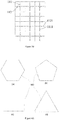
- a cross section of the columnar arrangement consisting of or including a plurality of millimeter wave scanning imaging devices 100 has a closed polygonal shape, each of sides of the polygonal shape is defined by one millimeter wave scanning imaging device 100, for example, one millimeter wave scanning imaging device 100 is located at one side face of the columnar arrangement.
- the closed polygonal shape may include a triangular shape, a quadrilateral shape, a pentagonal shape, a hexagonal shape or the like.
- the number of sides of the polygonal shape or the number of the millimeter wave scanning imaging devices may be determined according to factors such as sizes, locations of the security inspection areas of the security inspection scene or the public place, imaging resolution or the like.
- the columnar arrangement formed by a plurality of millimeter wave scanning imaging devices 100 is partially open or is open at a side face, and is not formed into a closed arrangement, so that its cross section has a polygonal outline, which for example forms only a part of polygon.
- This unclosed columnar arrangement can be placed in a corner of the security inspection scene or public place or against a building wall so as to scan and image the objects to be inspected from different orientations.
- the data processing device 200 is positioned in a closed or partially enclosed space surrounded by the plurality of millimeter wave scanning imaging devices 100.
- the display device 300 may be positioned at a location, for example, in a monitoring room, away from the millimeter wave scanning imaging devices, and in wired or wireless communication with the data processing device 200 to receive data from the data processing device.
- FIG. 2 schematically shows an arrangement of a millimeter wave scanning imaging device according to an exemplary embodiment of the present disclosure.
- a millimeter wave scanning imaging device 100 includes a first millimeter wave source 101, a second millimeter wave source 102, a mixer 103, a switch matrix 104, a transmitter module 105, a receiver module 106, and a millimeter wave transceiver antenna array 110 including a plurality of millimeter wave transmitting antennas and a plurality of millimeter wave receiving antennas.
- the first millimeter wave source 101 may be configured as a millimeter wave transmitting source for generating a first, transmitted millimeter wave signal; the second millimeter wave source may be configured as a reference source for generating a second, reference millimeter wave signal; for example, the first millimeter wave source 101 or the second millimeter wave source 102 may be an oscillator that produces a signal of a certain frequency.
- the mixer 103 is configured to mix in frequency the millimeter wave signals generated by the first millimeter wave source 101 and the second millimeter wave source 102 so as to form a frequency mixed signal as a reference signal.
- the switch matrix 104 is connected between the first millimeter wave source 101 and the transmitter module 105, and is configured to control switching of transmitting/receiving antennas, for example, to control switching of on-off states of the millimeter wave transmitting antennas and the millimeter wave receiving antennas.
- the switch matrix may control, through an electronic switch, the transmitting antennas to transmit millimeter wave signals in a certain order.
- the transmit antennas may be switched by the switch matrix to scan millimeter wave onto the objects to be inspected so that holographic data of the objects may be obtained.
- the switch matrix controls switching of on-off states of the millimeter wave transmitting antennas and the millimeter wave receiving antennas and control the transmitting antennas to transmit millimeter wave signals sequentially, such that when one millimeter wave transmitting antenna transmits a millimeter wave signal to the object to be inspected, only the millimeter wave receiving antennas which are associated with the one millimeter wave transmitting antenna (for example, which are arranged in a same one sub-array unit as the one millimeter wave transmitting antenna, as described below) receive reflected millimeter wave signals from the object simultaneously.
- the transmitting antennas may be controlled by the switch matrix to transmit millimeter wave signals sequentially, and all receiving antennas receive millimeter wave signals reflected from the objects simultaneously.
- the transmitter module 105 is configured to, under control of the switch matrix, drive the millimeter wave transmitting antennas to transmit millimeter waves based on the first millimeter wave signal generated by the first millimeter wave source 101.
- the transmitter module may multiply in frequency and amplify in power the first millimeter wave signal outputted from the first millimeter wave source so as to obtain a transmission signal the transmission signal is inputted to the transmitting antenna, so that the transmitting antenna transmits a millimeter wave.
- the transmitted millimeter wave may illuminate the object to be inspected and be reflected by the object.
- the millimeter wave reflected by the object is received by the receiving antenna, and the received millimeter wave signal can be inputted to the receiver module 106.
- the receiver module 406 can demodulate the received millimeter wave signal based on the reference signal outputted by the mixer, so as to obtain scan data, for example millimeter wave holographic data, of the object.
- the millimeter wave scanning imaging device 100 may further include a multi-channel analog-to-digital converter circuit 107 configured to convert the millimeter wave holographic data analog signal output from the receiver module 106 into a digital signal, which is outputted to and processed by the data processing device 200.
- a multi-channel analog-to-digital converter circuit 107 configured to convert the millimeter wave holographic data analog signal output from the receiver module 106 into a digital signal, which is outputted to and processed by the data processing device 200.
- one or more of the first millimeter wave source 101, the second millimeter wave source 102, the mixer 103, the switch matrix 104, the transmitter module 105, the receiver module 106 and the analog-to-digital converter circuit 107 described above may be integrated into one device, or may be implemented as various modules of the device.
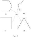
- the millimeter wave transceiver antenna array 110 includes a mesh-shaped or grid-like transceiver antenna array consisted of a plurality of sub-array units, each of which includes a transmitting antenna array 111 and a receiving antenna array 112.
- the millimeter wave transceiver antenna array may have a plane, curved or arc profile.
- respective sub-array units may have the same or similar configuration, for example the same or similar shape and/or size, the same or similar arrangement of transmitting antennas/receiving antennas.
- the transmitting antenna array 111 and/or the receiving antenna array 112 may include a linear antenna array.
- Each transmitting antenna linear array may have a plurality of millimeter wave transmitting antennas 1111 arranged linearly, and each receiving antenna linear array may have a plurality of millimeter wave receiving antennas 1121 arranged linearly.
- each sub-array unit has a rectangular shape such as a square, and includes two transmitting antenna linear arrays 111 arranged respectively along a pair of sides of the rectangular shape facing each other and two said receiving antenna linear arrays 112 arranged respectively along another pair of sides of the rectangular shape facing each other.
- each square sub-array unit includes first and second transmitting antenna linear arrays and first and second receiving antenna linear arrays, the first transmitting antenna linear array is opposite to the second transmitting antenna linear array, the first receiving antenna linear array is opposite to the second receiving antenna linear array, and the first and second receiving antenna linear arrays and the first and second receiving antenna linear arrays together form the square sub-array unit as its four sides. Two adjacent sub-array units share one transmitting antenna linear array or one receiving antenna linear array.
- each sub-array unit may be a mesh-shaped or grid-like transceiver array consisted of crossed sub-units, each crossed sub-unit includes a transmitting antenna linear array 111 and a receiving antenna linear array 112, which cross each other (such as are orthogonal to each other) to form a crisscross shape or a crisscross profile.
- the arrangement of the antennas in the millimeter wave transceiver antenna array is not limited to the embodiments shown in the Figures, and may be set according to actual requirements such that respective millimeter wave transceiver antenna array, which are oriented to different orientations in the security inspection scene or public place, can perform millimeter wave scanning imaging operations on objects to be inspected (e.g., pedestrians or persons to be inspected) within different inspection areas or ranges towards which they face.
- objects to be inspected e.g., pedestrians or persons to be inspected
- an optical camera 109 which is configured to capture an optical image of an object 1 to be inspected entering the security inspection scene, for determining whether or not the object to be inspected reaches the inspection area towards which a corresponding millimeter wave scanning imaging device faces before the corresponding millimeter wave scanning imaging device is started-up for scanning imaging.
- the scene monitoring type millimeter wave scanning imaging system 10 may be provided with or may include a plurality of optical cameras 109 each associated with a corresponding one of the millimeter wave scanning imaging devices 100 so as to capture the optical image of the object to be inspected entering the inspection area towards which the one millimeter wave scanning imaging device faces.
- the optical camera may record an optical image of the object to be inspected, which, for example, may be used to determine whether the object to be inspected reaches the correct detection area before starting the scan, and the optical camera may capture an optical image of the object during the scanning process. Further, at the same time, the data processing device may acquire the optical image of the object captured by the optical camera, and determine identity of the object by a face recognition technology.
- the data processing device may match the optical image of the inspected object to the millimeter wave image, so as to provide comprehensive inspection information, may output identity information of the object and security alarm information to the display device, so that the display device may display the alarm information within a red box at a corresponding position on the optical image, and of course, may also display the optical image and the millimeter wave image with a warning box or a cartoon picture with a warning box.
- An embodiment of the present disclosure also provides a security inspection method, in which the scene monitoring type millimeter wave scanning imaging system described above may be arranged in a security inspection scene or a public place to respectively perform millimeter wave scanning imaging operations on objects to be inspected located within inspection areas at different orientations of the security inspection scene or public place.
- the transmitting antennas may be controlled to sequentially transmit a millimeter wave signal, such that when one millimeter wave transmitting antenna transmits the millimeter wave signal to the object, only the millimeter wave receiving antenna(s), which is/are associated with the millimeter wave transmitting antennas (e.g., which is arranged in a same sub-array unit as the millimeter wave transmitting antenna), will receive the reflected millimeter wave signals from the object simultaneously, thereby avoiding signal interference to most extent as possible.
Landscapes
- Physics & Mathematics (AREA)
- Engineering & Computer Science (AREA)
- Remote Sensing (AREA)
- General Physics & Mathematics (AREA)
- Radar, Positioning & Navigation (AREA)
- Life Sciences & Earth Sciences (AREA)
- General Life Sciences & Earth Sciences (AREA)
- Geophysics (AREA)
- Electromagnetism (AREA)
- Computer Networks & Wireless Communication (AREA)
- Radar Systems Or Details Thereof (AREA)
Applications Claiming Priority (1)
| Application Number | Priority Date | Filing Date | Title |
|---|---|---|---|
| CN201810323716 | 2018-04-11 |
Publications (2)
| Publication Number | Publication Date |
|---|---|
| EP3553570A1 true EP3553570A1 (de) | 2019-10-16 |
| EP3553570B1 EP3553570B1 (de) | 2021-10-06 |
Family
ID=65615711
Family Applications (1)
| Application Number | Title | Priority Date | Filing Date |
|---|---|---|---|
| EP19168495.0A Active EP3553570B1 (de) | 2018-04-11 | 2019-04-10 | Millimeterwellenabtastendes bildgebungssystem zur frei- und grossraumüberwachung mit sicherheitsinspektionsverfahren |
Country Status (3)
| Country | Link |
|---|---|
| EP (1) | EP3553570B1 (de) |
| CN (2) | CN109459792B (de) |
| ES (1) | ES2903198T3 (de) |
Cited By (2)
| Publication number | Priority date | Publication date | Assignee | Title |
|---|---|---|---|---|
| CN112327268A (zh) * | 2020-11-12 | 2021-02-05 | 奥谱毫芯(深圳)科技有限公司 | 基于毫米波信号的危险目标识别方法、装置、系统及介质 |
| CN113435230A (zh) * | 2020-03-23 | 2021-09-24 | 中国电信股份有限公司 | 异常区域的检测方法、装置、系统和计算机可读存储介质 |
Families Citing this family (1)
| Publication number | Priority date | Publication date | Assignee | Title |
|---|---|---|---|---|
| CN109459792B (zh) * | 2018-04-11 | 2024-05-10 | 清华大学 | 场景监控式毫米波扫描成像系统和安全检查方法 |
Citations (5)
| Publication number | Priority date | Publication date | Assignee | Title |
|---|---|---|---|---|
| US20110163231A1 (en) * | 2008-09-17 | 2011-07-07 | Salmon Neil A | Security portal |
| CN105510911A (zh) * | 2015-12-25 | 2016-04-20 | 深圳市太赫兹科技创新研究院 | 基于线性调频的多人人体安检设备及方法 |
| US20170254750A1 (en) * | 2016-03-04 | 2017-09-07 | The Arizona Board Of Regents On Behalf Of The University Of Arizona | Reconfigurable reflect-array to realize task-specific compressive sensing in screening applications |
| WO2018032669A1 (zh) * | 2016-08-18 | 2018-02-22 | 华讯方舟科技有限公司 | 基于毫米波成像的全方位安检系统 |
| EP3287816A1 (de) * | 2016-08-25 | 2018-02-28 | Nuctech Company Limited | Millimeterwellen-bildgebungssystem |
Family Cites Families (12)
| Publication number | Priority date | Publication date | Assignee | Title |
|---|---|---|---|---|
| US6417502B1 (en) * | 1998-08-05 | 2002-07-09 | Microvision, Inc. | Millimeter wave scanning imaging system having central reflectors |
| US20080266165A1 (en) * | 2007-04-27 | 2008-10-30 | Robert Patrick Daly | System for deployment of a millimeter wave concealed object detection system |
| CN102590239B (zh) * | 2007-10-05 | 2014-01-15 | 清华大学 | 在液态物品检查系统中确定ct扫描位置的方法和设备 |
| US7782251B2 (en) * | 2007-10-06 | 2010-08-24 | Trex Enterprises Corp. | Mobile millimeter wave imaging radar system |
| CN103901485A (zh) * | 2012-12-27 | 2014-07-02 | 同方威视技术股份有限公司 | 一种人体安检系统 |
| CN104375143A (zh) * | 2013-08-15 | 2015-02-25 | 同方威视技术股份有限公司 | 毫米波三维全息扫描成像设备及人体或物品检查方法 |
| CN104375141A (zh) * | 2013-08-15 | 2015-02-25 | 同方威视技术股份有限公司 | 毫米波三维全息扫描成像设备及检查方法 |
| CA2925947C (en) * | 2013-10-01 | 2020-12-22 | Voti Inc. | Scanning system, method, and corresponding bracket |
| CN106896359A (zh) * | 2015-12-17 | 2017-06-27 | 上海铭剑电子科技有限公司 | 主动式毫米波三维全息成像系统及安检系统 |
| CN105388474B (zh) * | 2015-12-23 | 2018-05-25 | 同方威视技术股份有限公司 | 毫米波三维全息扫描成像设备及人体或物品检查方法 |
| CN106353832B (zh) * | 2016-09-18 | 2018-08-03 | 公安部第一研究所 | 一种快速通过式毫米波人体安检系统及方法 |
| CN109459792B (zh) * | 2018-04-11 | 2024-05-10 | 清华大学 | 场景监控式毫米波扫描成像系统和安全检查方法 |
-
2018
- 2018-12-28 CN CN201811626865.3A patent/CN109459792B/zh active Active
- 2018-12-28 CN CN201822239097.8U patent/CN209728193U/zh active Active
-
2019
- 2019-04-10 EP EP19168495.0A patent/EP3553570B1/de active Active
- 2019-04-10 ES ES19168495T patent/ES2903198T3/es active Active
Patent Citations (6)
| Publication number | Priority date | Publication date | Assignee | Title |
|---|---|---|---|---|
| US20110163231A1 (en) * | 2008-09-17 | 2011-07-07 | Salmon Neil A | Security portal |
| CN105510911A (zh) * | 2015-12-25 | 2016-04-20 | 深圳市太赫兹科技创新研究院 | 基于线性调频的多人人体安检设备及方法 |
| US20190025421A1 (en) * | 2015-12-25 | 2019-01-24 | Shenzhen Cct Thz Technology Co., Ltd. | Apparatus and method for security check of multiple human bodies based on linear frequency modulation |
| US20170254750A1 (en) * | 2016-03-04 | 2017-09-07 | The Arizona Board Of Regents On Behalf Of The University Of Arizona | Reconfigurable reflect-array to realize task-specific compressive sensing in screening applications |
| WO2018032669A1 (zh) * | 2016-08-18 | 2018-02-22 | 华讯方舟科技有限公司 | 基于毫米波成像的全方位安检系统 |
| EP3287816A1 (de) * | 2016-08-25 | 2018-02-28 | Nuctech Company Limited | Millimeterwellen-bildgebungssystem |
Cited By (3)
| Publication number | Priority date | Publication date | Assignee | Title |
|---|---|---|---|---|
| CN113435230A (zh) * | 2020-03-23 | 2021-09-24 | 中国电信股份有限公司 | 异常区域的检测方法、装置、系统和计算机可读存储介质 |
| CN113435230B (zh) * | 2020-03-23 | 2024-03-15 | 中国电信股份有限公司 | 异常区域的检测方法、装置、系统和计算机可读存储介质 |
| CN112327268A (zh) * | 2020-11-12 | 2021-02-05 | 奥谱毫芯(深圳)科技有限公司 | 基于毫米波信号的危险目标识别方法、装置、系统及介质 |
Also Published As
| Publication number | Publication date |
|---|---|
| CN109459792A (zh) | 2019-03-12 |
| CN209728193U (zh) | 2019-12-03 |
| CN109459792B (zh) | 2024-05-10 |
| ES2903198T3 (es) | 2022-03-31 |
| EP3553570B1 (de) | 2021-10-06 |
Similar Documents
| Publication | Publication Date | Title |
|---|---|---|
| EP3553570B1 (de) | Millimeterwellenabtastendes bildgebungssystem zur frei- und grossraumüberwachung mit sicherheitsinspektionsverfahren | |
| CN110308443B (zh) | 一种实波束电扫描快速成像人体安检方法及安检系统 | |
| EP3349036B1 (de) | Vorrichtung und verfahren zur dreidimensionalen holographischen abtastabbildung mit millimeterwellen | |
| EP3287816B1 (de) | Millimeterwellen-bildgebungssystem | |
| RU2595303C2 (ru) | Сканирующее устройство для формирования трехмерного голографического изображения в миллиметровом диапазоне волн и способ обследования с помощью такого устройства | |
| US8712093B2 (en) | Millimeter wave imaging method and system to detect concealed objects | |
| CN105932427B (zh) | 一种毫米波成像雷达一维阵列天线及时序控制方法 | |
| US11125906B2 (en) | Millimeter wave imaging-based omni-directional security detection system | |
| US20070075889A1 (en) | Interlaced linear array sampling technique for electromagnetic wave imaging | |
| CN105824021A (zh) | 一种基于模数混合二维相控阵射频多波束智能成像系统 | |
| CN106546981A (zh) | 运动人体安检成像系统和方法 | |
| US10585185B2 (en) | Security scanning system with walk-through-gate | |
| CN109407165A (zh) | 可扩展式毫米波安检系统、扫描单元及对人体进行安全检查的方法 | |
| CN109471195A (zh) | 毫米波太赫兹成像设备及物体识别分类方法 | |
| CN212623136U (zh) | 毫米波扫描成像安检设备及系统 | |
| US11777230B2 (en) | Antenna device, system, and transmission/reception method | |
| CN111103583A (zh) | 一种具有实时校准的三维射频成像系统和方法 | |
| KR20230148201A (ko) | 다방향 트랜스듀서 시스템 | |
| US8897599B2 (en) | Image system designed to scan for security threats | |
| CN110045367A (zh) | 柱面阵列天线目标体三维成像的装置 | |
| JP7815075B2 (ja) | レーダシステム及び検査方法 | |
| WO2009090406A1 (en) | Microwave imaging system | |
| RU153772U1 (ru) | Пассивный терагерцовый досмотровый комплекс | |
| JP2007124509A (ja) | アンテナ | |
| HK1212040B (zh) | 毫米波三维全息扫描成像设备及成像方法 |
Legal Events
| Date | Code | Title | Description |
|---|---|---|---|
| PUAI | Public reference made under article 153(3) epc to a published international application that has entered the european phase |
Free format text: ORIGINAL CODE: 0009012 |
|
| STAA | Information on the status of an ep patent application or granted ep patent |
Free format text: STATUS: THE APPLICATION HAS BEEN PUBLISHED |
|
| AK | Designated contracting states |
Kind code of ref document: A1 Designated state(s): AL AT BE BG CH CY CZ DE DK EE ES FI FR GB GR HR HU IE IS IT LI LT LU LV MC MK MT NL NO PL PT RO RS SE SI SK SM TR |
|
| AX | Request for extension of the european patent |
Extension state: BA ME |
|
| STAA | Information on the status of an ep patent application or granted ep patent |
Free format text: STATUS: REQUEST FOR EXAMINATION WAS MADE |
|
| 17P | Request for examination filed |
Effective date: 20200406 |
|
| STAA | Information on the status of an ep patent application or granted ep patent |
Free format text: STATUS: EXAMINATION IS IN PROGRESS |
|
| 17Q | First examination report despatched |
Effective date: 20200806 |
|
| GRAP | Despatch of communication of intention to grant a patent |
Free format text: ORIGINAL CODE: EPIDOSNIGR1 |
|
| STAA | Information on the status of an ep patent application or granted ep patent |
Free format text: STATUS: GRANT OF PATENT IS INTENDED |
|
| INTG | Intention to grant announced |
Effective date: 20210422 |
|
| GRAS | Grant fee paid |
Free format text: ORIGINAL CODE: EPIDOSNIGR3 |
|
| GRAA | (expected) grant |
Free format text: ORIGINAL CODE: 0009210 |
|
| STAA | Information on the status of an ep patent application or granted ep patent |
Free format text: STATUS: THE PATENT HAS BEEN GRANTED |
|
| AK | Designated contracting states |
Kind code of ref document: B1 Designated state(s): AL AT BE BG CH CY CZ DE DK EE ES FI FR GB GR HR HU IE IS IT LI LT LU LV MC MK MT NL NO PL PT RO RS SE SI SK SM TR |
|
| REG | Reference to a national code |
Ref country code: GB Ref legal event code: FG4D |
|
| REG | Reference to a national code |
Ref country code: CH Ref legal event code: EP Ref country code: AT Ref legal event code: REF Ref document number: 1436697 Country of ref document: AT Kind code of ref document: T Effective date: 20211015 |
|
| REG | Reference to a national code |
Ref country code: IE Ref legal event code: FG4D |
|
| REG | Reference to a national code |
Ref country code: DE Ref legal event code: R096 Ref document number: 602019008082 Country of ref document: DE |
|
| REG | Reference to a national code |
Ref country code: LT Ref legal event code: MG9D |
|
| REG | Reference to a national code |
Ref country code: NL Ref legal event code: MP Effective date: 20211006 |
|
| REG | Reference to a national code |
Ref country code: AT Ref legal event code: MK05 Ref document number: 1436697 Country of ref document: AT Kind code of ref document: T Effective date: 20211006 |
|
| REG | Reference to a national code |
Ref country code: ES Ref legal event code: FG2A Ref document number: 2903198 Country of ref document: ES Kind code of ref document: T3 Effective date: 20220331 |
|
| PG25 | Lapsed in a contracting state [announced via postgrant information from national office to epo] |
Ref country code: RS Free format text: LAPSE BECAUSE OF FAILURE TO SUBMIT A TRANSLATION OF THE DESCRIPTION OR TO PAY THE FEE WITHIN THE PRESCRIBED TIME-LIMIT Effective date: 20211006 Ref country code: LT Free format text: LAPSE BECAUSE OF FAILURE TO SUBMIT A TRANSLATION OF THE DESCRIPTION OR TO PAY THE FEE WITHIN THE PRESCRIBED TIME-LIMIT Effective date: 20211006 Ref country code: FI Free format text: LAPSE BECAUSE OF FAILURE TO SUBMIT A TRANSLATION OF THE DESCRIPTION OR TO PAY THE FEE WITHIN THE PRESCRIBED TIME-LIMIT Effective date: 20211006 Ref country code: BG Free format text: LAPSE BECAUSE OF FAILURE TO SUBMIT A TRANSLATION OF THE DESCRIPTION OR TO PAY THE FEE WITHIN THE PRESCRIBED TIME-LIMIT Effective date: 20220106 Ref country code: AT Free format text: LAPSE BECAUSE OF FAILURE TO SUBMIT A TRANSLATION OF THE DESCRIPTION OR TO PAY THE FEE WITHIN THE PRESCRIBED TIME-LIMIT Effective date: 20211006 |
|
| PG25 | Lapsed in a contracting state [announced via postgrant information from national office to epo] |
Ref country code: IS Free format text: LAPSE BECAUSE OF FAILURE TO SUBMIT A TRANSLATION OF THE DESCRIPTION OR TO PAY THE FEE WITHIN THE PRESCRIBED TIME-LIMIT Effective date: 20220206 Ref country code: SE Free format text: LAPSE BECAUSE OF FAILURE TO SUBMIT A TRANSLATION OF THE DESCRIPTION OR TO PAY THE FEE WITHIN THE PRESCRIBED TIME-LIMIT Effective date: 20211006 Ref country code: PT Free format text: LAPSE BECAUSE OF FAILURE TO SUBMIT A TRANSLATION OF THE DESCRIPTION OR TO PAY THE FEE WITHIN THE PRESCRIBED TIME-LIMIT Effective date: 20220207 Ref country code: PL Free format text: LAPSE BECAUSE OF FAILURE TO SUBMIT A TRANSLATION OF THE DESCRIPTION OR TO PAY THE FEE WITHIN THE PRESCRIBED TIME-LIMIT Effective date: 20211006 Ref country code: NO Free format text: LAPSE BECAUSE OF FAILURE TO SUBMIT A TRANSLATION OF THE DESCRIPTION OR TO PAY THE FEE WITHIN THE PRESCRIBED TIME-LIMIT Effective date: 20220106 Ref country code: NL Free format text: LAPSE BECAUSE OF FAILURE TO SUBMIT A TRANSLATION OF THE DESCRIPTION OR TO PAY THE FEE WITHIN THE PRESCRIBED TIME-LIMIT Effective date: 20211006 Ref country code: LV Free format text: LAPSE BECAUSE OF FAILURE TO SUBMIT A TRANSLATION OF THE DESCRIPTION OR TO PAY THE FEE WITHIN THE PRESCRIBED TIME-LIMIT Effective date: 20211006 Ref country code: HR Free format text: LAPSE BECAUSE OF FAILURE TO SUBMIT A TRANSLATION OF THE DESCRIPTION OR TO PAY THE FEE WITHIN THE PRESCRIBED TIME-LIMIT Effective date: 20211006 Ref country code: GR Free format text: LAPSE BECAUSE OF FAILURE TO SUBMIT A TRANSLATION OF THE DESCRIPTION OR TO PAY THE FEE WITHIN THE PRESCRIBED TIME-LIMIT Effective date: 20220107 |
|
| REG | Reference to a national code |
Ref country code: DE Ref legal event code: R097 Ref document number: 602019008082 Country of ref document: DE |
|
| PG25 | Lapsed in a contracting state [announced via postgrant information from national office to epo] |
Ref country code: SM Free format text: LAPSE BECAUSE OF FAILURE TO SUBMIT A TRANSLATION OF THE DESCRIPTION OR TO PAY THE FEE WITHIN THE PRESCRIBED TIME-LIMIT Effective date: 20211006 Ref country code: SK Free format text: LAPSE BECAUSE OF FAILURE TO SUBMIT A TRANSLATION OF THE DESCRIPTION OR TO PAY THE FEE WITHIN THE PRESCRIBED TIME-LIMIT Effective date: 20211006 Ref country code: RO Free format text: LAPSE BECAUSE OF FAILURE TO SUBMIT A TRANSLATION OF THE DESCRIPTION OR TO PAY THE FEE WITHIN THE PRESCRIBED TIME-LIMIT Effective date: 20211006 Ref country code: EE Free format text: LAPSE BECAUSE OF FAILURE TO SUBMIT A TRANSLATION OF THE DESCRIPTION OR TO PAY THE FEE WITHIN THE PRESCRIBED TIME-LIMIT Effective date: 20211006 Ref country code: DK Free format text: LAPSE BECAUSE OF FAILURE TO SUBMIT A TRANSLATION OF THE DESCRIPTION OR TO PAY THE FEE WITHIN THE PRESCRIBED TIME-LIMIT Effective date: 20211006 Ref country code: CZ Free format text: LAPSE BECAUSE OF FAILURE TO SUBMIT A TRANSLATION OF THE DESCRIPTION OR TO PAY THE FEE WITHIN THE PRESCRIBED TIME-LIMIT Effective date: 20211006 |
|
| PLBE | No opposition filed within time limit |
Free format text: ORIGINAL CODE: 0009261 |
|
| STAA | Information on the status of an ep patent application or granted ep patent |
Free format text: STATUS: NO OPPOSITION FILED WITHIN TIME LIMIT |
|
| 26N | No opposition filed |
Effective date: 20220707 |
|
| PG25 | Lapsed in a contracting state [announced via postgrant information from national office to epo] |
Ref country code: AL Free format text: LAPSE BECAUSE OF FAILURE TO SUBMIT A TRANSLATION OF THE DESCRIPTION OR TO PAY THE FEE WITHIN THE PRESCRIBED TIME-LIMIT Effective date: 20211006 |
|
| PG25 | Lapsed in a contracting state [announced via postgrant information from national office to epo] |
Ref country code: SI Free format text: LAPSE BECAUSE OF FAILURE TO SUBMIT A TRANSLATION OF THE DESCRIPTION OR TO PAY THE FEE WITHIN THE PRESCRIBED TIME-LIMIT Effective date: 20211006 |
|
| REG | Reference to a national code |
Ref country code: CH Ref legal event code: PL |
|
| REG | Reference to a national code |
Ref country code: BE Ref legal event code: MM Effective date: 20220430 |
|
| PG25 | Lapsed in a contracting state [announced via postgrant information from national office to epo] |
Ref country code: MC Free format text: LAPSE BECAUSE OF FAILURE TO SUBMIT A TRANSLATION OF THE DESCRIPTION OR TO PAY THE FEE WITHIN THE PRESCRIBED TIME-LIMIT Effective date: 20211006 Ref country code: LU Free format text: LAPSE BECAUSE OF NON-PAYMENT OF DUE FEES Effective date: 20220410 Ref country code: LI Free format text: LAPSE BECAUSE OF NON-PAYMENT OF DUE FEES Effective date: 20220430 Ref country code: CH Free format text: LAPSE BECAUSE OF NON-PAYMENT OF DUE FEES Effective date: 20220430 |
|
| PG25 | Lapsed in a contracting state [announced via postgrant information from national office to epo] |
Ref country code: BE Free format text: LAPSE BECAUSE OF NON-PAYMENT OF DUE FEES Effective date: 20220430 |
|
| PG25 | Lapsed in a contracting state [announced via postgrant information from national office to epo] |
Ref country code: IE Free format text: LAPSE BECAUSE OF NON-PAYMENT OF DUE FEES Effective date: 20220410 |
|
| P01 | Opt-out of the competence of the unified patent court (upc) registered |
Effective date: 20230528 |
|
| PG25 | Lapsed in a contracting state [announced via postgrant information from national office to epo] |
Ref country code: HU Free format text: LAPSE BECAUSE OF FAILURE TO SUBMIT A TRANSLATION OF THE DESCRIPTION OR TO PAY THE FEE WITHIN THE PRESCRIBED TIME-LIMIT; INVALID AB INITIO Effective date: 20190410 |
|
| PG25 | Lapsed in a contracting state [announced via postgrant information from national office to epo] |
Ref country code: MK Free format text: LAPSE BECAUSE OF FAILURE TO SUBMIT A TRANSLATION OF THE DESCRIPTION OR TO PAY THE FEE WITHIN THE PRESCRIBED TIME-LIMIT Effective date: 20211006 Ref country code: CY Free format text: LAPSE BECAUSE OF FAILURE TO SUBMIT A TRANSLATION OF THE DESCRIPTION OR TO PAY THE FEE WITHIN THE PRESCRIBED TIME-LIMIT Effective date: 20211006 |
|
| PG25 | Lapsed in a contracting state [announced via postgrant information from national office to epo] |
Ref country code: MT Free format text: LAPSE BECAUSE OF FAILURE TO SUBMIT A TRANSLATION OF THE DESCRIPTION OR TO PAY THE FEE WITHIN THE PRESCRIBED TIME-LIMIT Effective date: 20211006 |
|
| PGFP | Annual fee paid to national office [announced via postgrant information from national office to epo] |
Ref country code: DE Payment date: 20250417 Year of fee payment: 7 |
|
| PGFP | Annual fee paid to national office [announced via postgrant information from national office to epo] |
Ref country code: ES Payment date: 20250519 Year of fee payment: 7 |
|
| PGFP | Annual fee paid to national office [announced via postgrant information from national office to epo] |
Ref country code: IT Payment date: 20250430 Year of fee payment: 7 |
|
| PG25 | Lapsed in a contracting state [announced via postgrant information from national office to epo] |
Ref country code: TR Free format text: LAPSE BECAUSE OF FAILURE TO SUBMIT A TRANSLATION OF THE DESCRIPTION OR TO PAY THE FEE WITHIN THE PRESCRIBED TIME-LIMIT Effective date: 20211006 |
|
| PGFP | Annual fee paid to national office [announced via postgrant information from national office to epo] |
Ref country code: GB Payment date: 20260325 Year of fee payment: 8 |
|
| PGFP | Annual fee paid to national office [announced via postgrant information from national office to epo] |
Ref country code: FR Payment date: 20260325 Year of fee payment: 8 |