EP3553569B1 - Dispositif ct en spirale et procédé de reconstruction d'image tridimensionnelle - Google Patents
Dispositif ct en spirale et procédé de reconstruction d'image tridimensionnelle Download PDFInfo
- Publication number
- EP3553569B1 EP3553569B1 EP17879490.5A EP17879490A EP3553569B1 EP 3553569 B1 EP3553569 B1 EP 3553569B1 EP 17879490 A EP17879490 A EP 17879490A EP 3553569 B1 EP3553569 B1 EP 3553569B1
- Authority
- EP
- European Patent Office
- Prior art keywords
- ray
- spiral
- inspection
- receiving apparatuses
- ray receiving
- Prior art date
- Legal status (The legal status is an assumption and is not a legal conclusion. Google has not performed a legal analysis and makes no representation as to the accuracy of the status listed.)
- Active
Links
Images

Classifications
-
- G—PHYSICS
- G01—MEASURING; TESTING
- G01T—MEASUREMENT OF NUCLEAR OR X-RADIATION
- G01T1/00—Measuring X-radiation, gamma radiation, corpuscular radiation, or cosmic radiation
- G01T1/29—Measurement performed on radiation beams, e.g. position or section of the beam; Measurement of spatial distribution of radiation
- G01T1/2914—Measurement of spatial distribution of radiation
- G01T1/2985—In depth localisation, e.g. using positron emitters; Tomographic imaging (longitudinal and transverse section imaging; apparatus for radiation diagnosis sequentially in different planes, steroscopic radiation diagnosis)
-
- G—PHYSICS
- G01—MEASURING; TESTING
- G01N—INVESTIGATING OR ANALYSING MATERIALS BY DETERMINING THEIR CHEMICAL OR PHYSICAL PROPERTIES
- G01N23/00—Investigating or analysing materials by the use of wave or particle radiation, e.g. X-rays or neutrons, not covered by groups G01N3/00 – G01N17/00, G01N21/00 or G01N22/00
- G01N23/02—Investigating or analysing materials by the use of wave or particle radiation, e.g. X-rays or neutrons, not covered by groups G01N3/00 – G01N17/00, G01N21/00 or G01N22/00 by transmitting the radiation through the material
- G01N23/04—Investigating or analysing materials by the use of wave or particle radiation, e.g. X-rays or neutrons, not covered by groups G01N3/00 – G01N17/00, G01N21/00 or G01N22/00 by transmitting the radiation through the material and forming images of the material
- G01N23/046—Investigating or analysing materials by the use of wave or particle radiation, e.g. X-rays or neutrons, not covered by groups G01N3/00 – G01N17/00, G01N21/00 or G01N22/00 by transmitting the radiation through the material and forming images of the material using tomography, e.g. computed tomography [CT]
-
- G—PHYSICS
- G01—MEASURING; TESTING
- G01V—GEOPHYSICS; GRAVITATIONAL MEASUREMENTS; DETECTING MASSES OR OBJECTS; TAGS
- G01V5/00—Prospecting or detecting by the use of ionising radiation, e.g. of natural or induced radioactivity
- G01V5/20—Detecting prohibited goods, e.g. weapons, explosives, hazardous substances, contraband or smuggled objects
- G01V5/22—Active interrogation, i.e. by irradiating objects or goods using external radiation sources, e.g. using gamma rays or cosmic rays
- G01V5/226—Active interrogation, i.e. by irradiating objects or goods using external radiation sources, e.g. using gamma rays or cosmic rays using tomography
-
- G—PHYSICS
- G01—MEASURING; TESTING
- G01N—INVESTIGATING OR ANALYSING MATERIALS BY DETERMINING THEIR CHEMICAL OR PHYSICAL PROPERTIES
- G01N2223/00—Investigating materials by wave or particle radiation
- G01N2223/40—Imaging
- G01N2223/419—Imaging computed tomograph
-
- G—PHYSICS
- G01—MEASURING; TESTING
- G01T—MEASUREMENT OF NUCLEAR OR X-RADIATION
- G01T1/00—Measuring X-radiation, gamma radiation, corpuscular radiation, or cosmic radiation
- G01T1/29—Measurement performed on radiation beams, e.g. position or section of the beam; Measurement of spatial distribution of radiation
- G01T1/2914—Measurement of spatial distribution of radiation
-
- G—PHYSICS
- G01—MEASURING; TESTING
- G01V—GEOPHYSICS; GRAVITATIONAL MEASUREMENTS; DETECTING MASSES OR OBJECTS; TAGS
- G01V5/00—Prospecting or detecting by the use of ionising radiation, e.g. of natural or induced radioactivity
- G01V5/20—Detecting prohibited goods, e.g. weapons, explosives, hazardous substances, contraband or smuggled objects
- G01V5/22—Active interrogation, i.e. by irradiating objects or goods using external radiation sources, e.g. using gamma rays or cosmic rays
- G01V5/224—Multiple energy techniques using one type of radiation, e.g. X-rays of different energies
Definitions
- the CT technology has gradually evolved from scanning using a thin X-ray beam, a small fan beam, or a large fan beam to scanning using spiral CT.
- the difference from the initial normal CT technology is in that, during scanning with the spiral CT, both a scanning bracket and an object to be detected are continuously moved, an X-ray source is spirally rotated relative to the object, and detectors continuously collect projection data, so as to obtain a three-dimensional image of the object to be detected, which may greatly shorten time for scanning.
- a resolution capability of the CT technology itself for densities and atomic numbers may further improve effects of material recognition during inspection.
- the first direction is a vertical direction.
- a center of the circumference of the slip ring coincides with a center of the inspection space.
- the X-ray sources are X-ray accelerators.
- data in the overlapping region is processed using a compressive sensing technique.
- spiral CT device With the spiral CT device according to the present disclosure, large objects may be inspected while ensuring a small system size, a short inspection time, and a high inspection quality. Thereby, the problems in the conventional techniques described above are solved, thereby satisfying the needs of airports for inspection of large cargos.
- Fig. 1 illustrates a structural diagram of a spiral CT device 100 according to an embodiment of the present disclosure.
- the spiral CT device 100 illustrated comprises an inspection station 110, a rotational supporting apparatus 120, two X-ray sources 130-1 and 130-2 (collectively referred to as 130 hereinafter), and two X-ray receiving apparatuses 140-1 and 140-2 (collectively referred to as 140 hereinafter).
- 130 two X-ray sources 130-1 and 130-2
- 140 two X-ray receiving apparatuses 140-1 and 140-2
- the inspection station 110 is configured to carry an object to be inspected.
- the inspection station 110 defines an inspection space which is located above the inspection station and is used for accommodating the object to be inspected.
- the inspection space 150 may be physically defined by a physical component (for example, a wall panel built on the inspection station 110) or defined by other technical means (for example, infrared detection) in an auxiliary manner.
- the inspection space 150 may also be defined without any physical components, but instead it is agreed that there is a space of a particular size above the inspection station 110.
- the inspection station 110 is movable in a first direction and/or in a direction perpendicular to the first direction.
- the movement in the first direction makes it convenient to place the object to be inspected.
- the inspection station 110 is firstly brought down to a suitable height, and after the object to be inspected is placed on the inspection station 110, the inspection station 110 is raised to a height suitable for CT measurement.
- the movement in the direction perpendicular to the first direction makes it convenient to perform the spiral CT inspection, and a speed of the horizontal movement may be determined by a rotation period and a measurement length.
- the first direction is a vertical direction (as shown in Fig. 1 ).
- the inspection station 110 In a detection state, the inspection station 110 is rotatable in the direction (as indicated by the horizontal direction in Fig. 1 ) perpendicular to the first direction, so that the inspection station 110 cooperatively rotates with the rotational supporting apparatus 120 described below to realize helical scanning of the object to be inspected.
- the rotational supporting apparatus 120 is shown as a ring in Fig. 1 . It may be seen that the rotational supporting apparatus 120 is shown as a slip ring in Fig. 1 . However, it should be understood that in other embodiments of the
- the X-ray sources 130 are X-ray accelerators for providing high-energy X-ray beams.
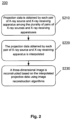
- Fig. 2 illustrates a flowchart of a method 200 for reconstructing a three-dimensional image from projection data obtained by a CT device according to the present disclosure.
- This method 200 is not encompassed by the wording of the claims but is considered as useful for understanding the invention.
- the CT device is not limited to the spiral CT device described in the embodiments of the present disclosure (as described above with reference to Fig. 1 ) as long as the CT device comprises a plurality of pairs of X-ray sources and X-ray receiving apparatuses.
- the spiral CT device shown in Fig. 1 will be taken as an example.
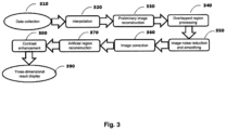
- a three-dimensional image is reconstructed using an image reconstruction algorithm, for example, reconstruction methods such as the Filtered Back Projection (FBP) reconstruction method, or the iterative Ordered Subset maximum Expectation Method (OSEM) or the Algebraic Reconstruction Technique (ART) in combination with the FBP algorithm etc.
- FBP Filtered Back Projection
- OSEM iterative Ordered Subset maximum Expectation Method
- ART Algebraic Reconstruction Technique
- data in the overlapping region is processed using a compressive sensing technique.
- Fig. 1 by taking the case shown in Fig. 1 as an example, if a plurality of rows of detectors are used as the X-ray receiving apparatuses 140, since the X-ray sources 130 have a certain size, two target points may not completely coincide. In order to completely cover the object to be inspected with the rays, it may inevitably enable partial overlapping of the X-ray receiving apparatuses 140-1 and 140-2 (as shown in Fig. 1 ). Conventional image reconstruction algorithms (for example, the FBP) cannot be used for overlapping data in this partial overlapping region.
- Conventional image reconstruction algorithms for example, the FBP
- the overlapping projection data may be regarded as a sum of a plurality of exponential functions, and cannot be expanded "in a non-destructive manner" to a linear function with a limited length; and secondly, if the object to be inspected is discretized, the overlapping projection data makes the imaging system underdetermined, which results in failure in acquisition of a correct solution.
- certain processing such as the compressive sensing technique described above, is required to be used. Under conditions that data sparsity is satisfied and random sampling is implemented, image quality may be recovered using a sampling frequency much less than an Nyquist sampling frequency.
- the image to be reconstructed may firstly be converted into a gradient image, and then an I 1 mode of the gradient image is minimized.
- the image reconstruction process is transformed into a nonlinear optimization problem under constraint conditions, which may be solved by the iterative reconstruction algorithm, the gradient descent method or the convex set mapping method etc.
- Fig. 2 illustrates a flowchart of a method 200 for reconstructing a three-dimensional image from projection data obtained by a CT device according to an embodiment of the present disclosure.
- the CT device is not limited to the spiral CT device described in the embodiments of the present disclosure (as described above with reference to Fig. 1 ) as long as the CT device comprises a plurality of pairs of X-ray sources and X-ray receiving apparatuses.
- the spiral CT device shown in Fig. 1 will be taken as an example.
- the method 200 starts at step S210, in which corresponding projection data is obtained by each pair of X-ray source and X-ray receiving apparatus among the plurality of pairs of X-ray sources and X-ray receiving apparatuses. Then, in step S220, the projection data obtained by each pair of X-ray source and X-ray receiving apparatus is interpolated. Finally, in step S230, a three-dimensional image is reconstructed based on the interpolated projection data using image reconstruction algorithms.
- step S230 for two pairs of X-ray sources and X-ray receiving apparatuses having an overlapped projection portion, an image reconstruction algorithm for data corresponding to the overlapped projection portion in the interpolated projection data obtained using the two pairs of X-ray sources and X-ray receiving apparatuses is different from an image reconstruction algorithm for data corresponding to remaining portions except for the overlapped projection portion in the interpolated projection data.
- step S210 corresponding projection data is obtained by each pair of X-ray source and X-ray receiving apparatus among the plurality of pairs of X-ray sources and X-ray receiving apparatuses.
- the X-ray sources 130-1 and 130-2 emit X-rays respectively
- the X-ray receiving apparatuses 140-1 and 140-2 receive the X-rays passing through the object to be inspected respectively, to obtain corresponding projection data respectively.
- the X-ray sources 130-1 and 130-2 emit X-rays respectively
- the X-ray receiving apparatuses 140-1 and 140-2 receive the X-rays passing through the object to be inspected respectively, to obtain corresponding projection data respectively.
- the X-ray receiving apparatuses 140-1 and 140-2 receive the X-rays passing through the object to be inspected respectively, to obtain corresponding projection data respectively.
- the X-ray receiving apparatuses 140-1 and 140-2 receive the X-rays passing through the object to be inspected respectively, to obtain corresponding projection data respectively.
- the two X-ray sources 130-1 and 130-2 have a coverage including the entire inspection space (this is true not only in a dimension corresponding to the paper sheets, but also in various slices distributed in a direction perpendicular to the paper sheets).
- the reproduction of the three-dimensional image of the object to be inspected may be realized using data obtained using the X-ray sources 130-1 and 130-2 and the X-ray receiving apparatuses 140-1 and 140-2.
- step S220 the projection data obtained using each pair of X-ray source and X-ray receiving apparatus is interpolated.
- the interpolation step is implemented using linear interpolation. Still
- the spiral CT device shown in Fig. 1 as an example, since projection data in a slice depending on any of the scanning axes is incomplete, it is necessary to fill blank regions between existing data using the existing data through interpolation to avoid volume artifacts from occurring during reconstruction.
- the exemplary interpolation method has been described in the description of Fig. 1 , and details thereof will not be described herein again.
- the projection data enriched by interpolation will be used for reconstruction in a next step.
- step S230 a three-dimensional image is reconstructed based on the interpolated projection data using image reconstruction algorithms.
- the image reconstruction algorithms may be conventional image reconstruction algorithms, for example, the FBP.
- an algorithm for example, the compressive sensing technique
- the exemplary algorithm for the overlapping region has been described above with respect to Fig. 1 and will not be described again here.
Landscapes
- Physics & Mathematics (AREA)
- Life Sciences & Earth Sciences (AREA)
- General Physics & Mathematics (AREA)
- Health & Medical Sciences (AREA)
- High Energy & Nuclear Physics (AREA)
- Geophysics (AREA)
- General Life Sciences & Earth Sciences (AREA)
- General Health & Medical Sciences (AREA)
- Nuclear Medicine, Radiotherapy & Molecular Imaging (AREA)
- Radiology & Medical Imaging (AREA)
- Theoretical Computer Science (AREA)
- Biochemistry (AREA)
- Analytical Chemistry (AREA)
- Immunology (AREA)
- Pathology (AREA)
- Chemical & Material Sciences (AREA)
- Pulmonology (AREA)
- Engineering & Computer Science (AREA)
- Molecular Biology (AREA)
- Spectroscopy & Molecular Physics (AREA)
- Apparatus For Radiation Diagnosis (AREA)
- Analysing Materials By The Use Of Radiation (AREA)
Claims (9)
- Dispositif de tomodensitométrie, CT, spiralée permettant l'inspection de grandes cargaisons, comprenant :un poste d'inspection (110) servant à transporter un objet à inspecter sur sa surface porteuse de celui-ci, dans lequel un espace d'inspection (150) est défini au-dessus de la surface porteuse, une direction normale pour la surface porteuse est une première direction, et le poste d'inspection (110) est apte à se déplacer le long d'une deuxième direction perpendiculaire à la première direction pour amener l'objet à inspecter à traverser l'espace d'inspection (150) ;un appareil de support rotatif (120) disposé autour de l'espace d'inspection dans un plan perpendiculaire à la deuxième direction et pouvant tourner autour de l'espace d'inspection (150) ; caractérisé en ce que le dispositif de CT spiralée comprend en outreune pluralité d'accélérateurs de rayons X (130-1, 130-2) situés sur l'appareil de support rotatif (120) et configurés pour transmettre des rayons X destinés à traverser l'espace d'inspection (150) ; etune pluralité d'appareils de réception de rayons X (140-1, 140-2) en correspondance biunivoque avec la pluralité d'accélérateurs de rayons X, la pluralité d'appareils de réception de rayons X (140-1, 140-2) étant situés sur l'appareil de support rotatif (120) et à l'opposé de la pluralité d'accélérateurs de rayons X (130-1, 130-2), respectivement, la pluralité d'appareils de réception de rayons X (140-1, 140-2) étant configurés pour collecter les rayons X traversant l'espace d'inspection (150),dans lequel la pluralité d'accélérateurs de rayons X (130-1, 130-2) et la pluralité d'appareils de réception de rayons X (140-1, 140-2) peuvent tourner avec l'appareil de support rotatif (120) ;dans lequel la pluralité d'accélérateurs de rayons X (130-1, 130-2) sont étroitement disposés sur l'appareil de support rotatif (120), et des faisceaux de rayons X en éventail fournis par la pluralité d'accélérateurs de rayons X (130-1, 130-2) couvrent l'espace d'inspection (150) avec un degré minimum de chevauchement.
- Dispositif de CT spiralée selon la revendication 1, dans lequel le poste d'inspection (110) est également mobile le long de la première direction.
- Dispositif de CT spiralée selon la revendication 2, dans lequel la première direction est une direction verticale.
- Dispositif de CT spiralée selon la revendication 1, dans lequel l'appareil de support rotatif (120) est une bague collectrice, la pluralité d'accélérateurs de rayons X (130-1, 130-2) et la pluralité d'appareils de réception de rayons X (140-1, 140-2) sont disposés sur une circonférence de la bague collectrice, et un accélérateur de rayons X (130) et un appareil de réception de rayons X correspondant (140) sont disposés sur des côtés opposés de la circonférence par rapport au centre de la circonférence.
- Dispositif de CT spiralée selon la revendication 4, dans lequel le centre de la circonférence de la bague collectrice coïncide avec le centre de l'espace d'inspection (150) dans l'état de détection.
- Dispositif de CT spiralée selon la revendication 1, dans lequel l'appareil de support rotatif (120) est un support.
- Dispositif de CT spiralée selon la revendication 1, dans lequel les appareils de réception de rayons X (140-1, 140-2) comprennent chacun une pluralité de rangées de détecteurs.
- Dispositif de CT spiralée selon la revendication 1, comprenant en outre : un processeur connecté à la pluralité d'appareils de réception de rayons X (140-1, 140-2) et configuré pour traiter des signaux des rayons X collectés et reconstruire une image tridimensionnelle de l'objet à inspecter,
dans lequel le processeur est configuré pour reconstruire l'image tridimensionnelle à l'aide d'un procédé d'interpolation linéaire. - Dispositif de CT spiralée selon la revendication 8, dans lequel, lorsque les couvertures de deux appareils de réception de rayons X adjacents de la pluralité d'appareils de réception de rayons X (140-1, 140-2) présentent une région de chevauchement, les signaux dans la région de chevauchement sont traités à l'aide d'une technique de détection compressive.
Applications Claiming Priority (2)
| Application Number | Priority Date | Filing Date | Title |
|---|---|---|---|
| CN201611117356.9A CN106526686B (zh) | 2016-12-07 | 2016-12-07 | 螺旋ct设备和三维图像重建方法 |
| PCT/CN2017/096017 WO2018103355A1 (fr) | 2016-12-07 | 2017-08-04 | Dispositif ct en spirale et procédé de reconstruction d'image tridimensionnelle |
Publications (3)
| Publication Number | Publication Date |
|---|---|
| EP3553569A1 EP3553569A1 (fr) | 2019-10-16 |
| EP3553569A4 EP3553569A4 (fr) | 2020-08-12 |
| EP3553569B1 true EP3553569B1 (fr) | 2025-07-09 |
Family
ID=58341972
Family Applications (1)
| Application Number | Title | Priority Date | Filing Date |
|---|---|---|---|
| EP17879490.5A Active EP3553569B1 (fr) | 2016-12-07 | 2017-08-04 | Dispositif ct en spirale et procédé de reconstruction d'image tridimensionnelle |
Country Status (4)
| Country | Link |
|---|---|
| US (1) | US11346975B2 (fr) |
| EP (1) | EP3553569B1 (fr) |
| CN (1) | CN106526686B (fr) |
| WO (1) | WO2018103355A1 (fr) |
Families Citing this family (5)
| Publication number | Priority date | Publication date | Assignee | Title |
|---|---|---|---|---|
| CN106526686B (zh) * | 2016-12-07 | 2019-05-07 | 同方威视技术股份有限公司 | 螺旋ct设备和三维图像重建方法 |
| DE102018201510A1 (de) * | 2018-02-01 | 2019-08-01 | Robert Bosch Gmbh | Vorrichtung zur Übertragung eines Signals mittels Wellenleitern |
| WO2020047831A1 (fr) * | 2018-09-07 | 2020-03-12 | Shenzhen Xpectvision Technology Co., Ltd. | Capteur d'image comprenant des détecteurs de rayonnement de différentes orientations |
| US11016042B2 (en) * | 2019-08-13 | 2021-05-25 | GE Sensing & Inspection Technologies, GmbH | Fast industrial computed tomography for large objects |
| JP7257924B2 (ja) * | 2019-09-09 | 2023-04-14 | 株式会社ミツトヨ | X線計測装置の校正方法 |
Family Cites Families (65)
| Publication number | Priority date | Publication date | Assignee | Title |
|---|---|---|---|---|
| US5805659A (en) * | 1996-09-30 | 1998-09-08 | Siemens Corporate Research, Inc. | Method and apparatus for spiral scan region of interest imaging |
| US6229870B1 (en) * | 1998-11-25 | 2001-05-08 | Picker International, Inc. | Multiple fan beam computed tomography system |
| WO2002026134A1 (fr) * | 2000-09-28 | 2002-04-04 | Philips Medical Systems Technologies Ltd. | Tomodensitometre a grande couverture a coherence temporelle |
| US6813374B1 (en) * | 2001-04-25 | 2004-11-02 | Analogic Corporation | Method and apparatus for automatic image quality assessment |
| US7103137B2 (en) * | 2002-07-24 | 2006-09-05 | Varian Medical Systems Technology, Inc. | Radiation scanning of objects for contraband |
| US8837669B2 (en) * | 2003-04-25 | 2014-09-16 | Rapiscan Systems, Inc. | X-ray scanning system |
| GB0309379D0 (en) * | 2003-04-25 | 2003-06-04 | Cxr Ltd | X-ray scanning |
| US8223919B2 (en) * | 2003-04-25 | 2012-07-17 | Rapiscan Systems, Inc. | X-ray tomographic inspection systems for the identification of specific target items |
| US7388941B2 (en) * | 2003-08-07 | 2008-06-17 | Xoran Technologies, Inc. | CT extremity scanner |
| US20050117700A1 (en) * | 2003-08-08 | 2005-06-02 | Peschmann Kristian R. | Methods and systems for the rapid detection of concealed objects |
| US7333587B2 (en) * | 2004-02-27 | 2008-02-19 | General Electric Company | Method and system for imaging using multiple offset X-ray emission points |
| US7885375B2 (en) * | 2004-02-27 | 2011-02-08 | General Electric Company | Method and system for X-ray imaging |
| US7324625B2 (en) * | 2004-05-27 | 2008-01-29 | L-3 Communications Security And Detection Systems, Inc. | Contraband detection systems using a large-angle cone beam CT system |
| CN101041989A (zh) * | 2004-08-05 | 2007-09-26 | 邱则有 | 一种钢筋砼立体承力结构楼盖 |
| WO2006135837A1 (fr) * | 2005-06-10 | 2006-12-21 | Xoran Technologies, Inc. | Tomodensitometre a sources multiples |
| CN100401983C (zh) * | 2005-10-27 | 2008-07-16 | 上海交通大学 | 基于双源双螺旋多层螺旋ct的重建方法 |
| US7492860B2 (en) * | 2006-04-04 | 2009-02-17 | Ge Security, Inc. | Apparatus and method for controlling start and stop operations of a computed tomography imaging system |
| JP5214916B2 (ja) * | 2006-07-19 | 2013-06-19 | 株式会社東芝 | X線ct装置及びそのデータ処理方法 |
| EP2052240A1 (fr) * | 2006-08-11 | 2009-04-29 | Philips Intellectual Property & Standards GmbH | Système et procédé pour acquérir des données d'image |
| US7388940B1 (en) * | 2006-11-24 | 2008-06-17 | General Electric Company | Architectures for cardiac CT based on area x-ray sources |
| US7428292B2 (en) * | 2006-11-24 | 2008-09-23 | General Electric Company | Method and system for CT imaging using multi-spot emission sources |
| WO2008122971A1 (fr) * | 2007-04-10 | 2008-10-16 | Arineta Ltd. | Tomographie par ordinateur (ct) à faisceau conique |
| CN100462051C (zh) * | 2007-05-24 | 2009-02-18 | 上海交通大学 | 多源螺旋ct并行重建系统 |
| JP4858613B2 (ja) * | 2007-07-11 | 2012-01-18 | 株式会社島津製作所 | 放射線撮像装置 |
| CN101842052B (zh) * | 2007-07-19 | 2013-11-20 | 北卡罗来纳大学查珀尔希尔分校 | 固定x射线数字化乳房断层合成系统和相关方法 |
| JP5179136B2 (ja) * | 2007-10-02 | 2013-04-10 | ジーイー・メディカル・システムズ・グローバル・テクノロジー・カンパニー・エルエルシー | X線ct装置 |
| CN101945614B (zh) * | 2008-02-14 | 2013-12-04 | 皇家飞利浦电子股份有限公司 | 具有平板探测器的多源成像系统 |
| JP5677301B2 (ja) * | 2008-09-10 | 2015-02-25 | アナロジック コーポレーション | 複数ピクセルx線源を使用したコンピュータ断層撮影走査システム及び方法 |
| US8139709B2 (en) * | 2008-09-15 | 2012-03-20 | University Of Utah Research Foundation | Staggered circular scans for CT imaging |
| US8194821B2 (en) * | 2008-09-26 | 2012-06-05 | Varian Medical Systems, Inc. | Methods, systems, and computer-program products to correct degradation in tomographic images caused by extraneous radiation |
| US8862206B2 (en) * | 2009-11-12 | 2014-10-14 | Virginia Tech Intellectual Properties, Inc. | Extended interior methods and systems for spectral, optical, and photoacoustic imaging |
| DE102009057716A1 (de) * | 2009-12-10 | 2011-06-16 | Siemens Aktiengesellschaft | Rauschreduktion bei Dual-Source CT Aufnahmen |
| US20110142201A1 (en) * | 2009-12-15 | 2011-06-16 | General Electric Company | Multi-view imaging system and method |
| US8270562B2 (en) * | 2009-12-21 | 2012-09-18 | General Electric Company | Multiple X-ray tube system and method of making same |
| JP5677738B2 (ja) * | 2009-12-24 | 2015-02-25 | 株式会社東芝 | X線コンピュータ断層撮影装置 |
| CA2783485A1 (fr) * | 2010-01-13 | 2011-07-21 | The Australian National University | Procede et systeme d'imagerie tomographique informatisee |
| EP2537397B1 (fr) * | 2010-02-16 | 2020-11-18 | Kristofer J. Roe | Inspection de cargaison modulaire adaptative |
| US20130016805A1 (en) * | 2011-07-15 | 2013-01-17 | Toshiba Medical Systems Corporation | Method and system for acquiring sparse channel data and for image processing utilizing iterative reconstruction algorithms |
| KR101477543B1 (ko) * | 2011-07-22 | 2014-12-31 | 삼성전자주식회사 | 엑스선 촬영 장치 및 방법 |
| US9069092B2 (en) * | 2012-02-22 | 2015-06-30 | L-3 Communication Security and Detection Systems Corp. | X-ray imager with sparse detector array |
| DE102012204350B4 (de) * | 2012-03-20 | 2021-12-02 | Siemens Healthcare Gmbh | Verfahren zur Energie-Kalibrierung quantenzählender Röntgendetektoren in einem Dual-Source Computertomographen |
| WO2013187970A2 (fr) * | 2012-05-14 | 2013-12-19 | The General Hospital Corporation | Procédé d'imagerie par rayons x à contraste de phase à source codée |
| CN102697517A (zh) | 2012-06-25 | 2012-10-03 | 苏州生物医学工程技术研究所 | 移动ct扫描仪及操作方法 |
| US9417340B2 (en) * | 2012-07-06 | 2016-08-16 | Morpho Detection, Llc | Compact geometry CT system |
| CN102835971A (zh) * | 2012-09-20 | 2012-12-26 | 苏州瑞派宁科技有限公司 | Ct扫描装置、旋转ct系统及其检查方法 |
| CN103903303B (zh) * | 2012-12-27 | 2018-01-30 | 清华大学 | 三维模型创建方法和设备 |
| KR102090597B1 (ko) * | 2012-12-28 | 2020-03-19 | 삼성전자주식회사 | 엑스선 촬영 장치 및 엑스선 영상 처리 방법 |
| US10004464B2 (en) * | 2013-01-31 | 2018-06-26 | Duke University | System for improved compressive tomography and method therefor |
| US9778391B2 (en) * | 2013-03-15 | 2017-10-03 | Varex Imaging Corporation | Systems and methods for multi-view imaging and tomography |
| WO2015012850A1 (fr) * | 2013-07-25 | 2015-01-29 | Analogic Corporation | Génération de signature de diffraction d'un élément à l'intérieur d'un objet |
| WO2015048874A1 (fr) * | 2013-10-01 | 2015-04-09 | Voti Inc. | Système de balayage, procédé, et support correspondant |
| CN104749197B (zh) * | 2013-12-26 | 2017-08-11 | 清华大学 | Ct系统及其方法 |
| CN104374783B (zh) * | 2013-12-26 | 2017-06-16 | 清华大学 | Ct系统及其方法 |
| CN104749648A (zh) * | 2013-12-27 | 2015-07-01 | 清华大学 | 多能谱静态ct设备 |
| DE102014200679A1 (de) * | 2014-01-16 | 2015-07-16 | Smiths Heimann Gmbh | Verfahren und Röntgenprüfanlage, insbesondere zur zerstörungsfreien Inspektion von Objekten |
| US9865066B2 (en) * | 2014-05-06 | 2018-01-09 | Astrophysics Inc. | Computed tomography system for cargo and transported containers |
| CN105093342B (zh) * | 2014-05-14 | 2017-11-17 | 同方威视技术股份有限公司 | 螺旋ct系统及重建方法 |
| WO2017011057A2 (fr) * | 2015-04-27 | 2017-01-19 | GREEN, Christopher, K. | Système d'inspection à rayons x à quatre plans |
| US10345479B2 (en) * | 2015-09-16 | 2019-07-09 | Rapiscan Systems, Inc. | Portable X-ray scanner |
| US10119923B2 (en) * | 2015-10-19 | 2018-11-06 | L3 Security & Detection Systems, Inc. | Systems and methods for image reconstruction at high computed tomography pitch |
| CN105784737B (zh) * | 2016-03-29 | 2021-06-22 | 清华大学 | 集装箱ct检查系统 |
| JP7097819B2 (ja) * | 2016-05-13 | 2022-07-08 | コーニンクレッカ フィリップス エヌ ヴェ | 4dイメージングのためのマルチビームx線露光のためのシステム及び方法 |
| US20180038807A1 (en) * | 2016-08-08 | 2018-02-08 | Adaptix Ltd. | Method and system for reconstructing 3-dimensional images from spatially and temporally overlapping x-rays |
| CN206515487U (zh) * | 2016-12-07 | 2017-09-22 | 同方威视技术股份有限公司 | 螺旋ct设备 |
| CN106526686B (zh) * | 2016-12-07 | 2019-05-07 | 同方威视技术股份有限公司 | 螺旋ct设备和三维图像重建方法 |
-
2016
- 2016-12-07 CN CN201611117356.9A patent/CN106526686B/zh active Active
-
2017
- 2017-08-04 EP EP17879490.5A patent/EP3553569B1/fr active Active
- 2017-08-04 WO PCT/CN2017/096017 patent/WO2018103355A1/fr not_active Ceased
- 2017-08-04 US US16/467,140 patent/US11346975B2/en active Active
Also Published As
| Publication number | Publication date |
|---|---|
| CN106526686A (zh) | 2017-03-22 |
| EP3553569A4 (fr) | 2020-08-12 |
| WO2018103355A1 (fr) | 2018-06-14 |
| EP3553569A1 (fr) | 2019-10-16 |
| US11346975B2 (en) | 2022-05-31 |
| CN106526686B (zh) | 2019-05-07 |
| US20190317240A1 (en) | 2019-10-17 |
Similar Documents
| Publication | Publication Date | Title |
|---|---|---|
| EP2273257B1 (fr) | Système d'imagerie utilisant un balayage à trajectoire en ligne droite et procédé correspondant | |
| EP3553569B1 (fr) | Dispositif ct en spirale et procédé de reconstruction d'image tridimensionnelle | |
| EP2942649B1 (fr) | Système de tomographie assistée par ordinateur pour un chargement et des récipients transportés | |
| US7499522B2 (en) | Cargo security inspection system and method | |
| EP1953700B1 (fr) | Systeme et procede de reconstruction d'image par balayage suivant une trajectoire rectiligne | |
| US7512213B2 (en) | Multiple-view-angle cargo security inspection method and system | |
| US8582857B2 (en) | Dual-energy material identification method and apparatus with undersampling | |
| US7672427B2 (en) | Imaging system | |
| US9466137B2 (en) | Spiral CT systems and reconstruction methods | |
| CN101900694B (zh) | 基于直线轨迹扫描的双能欠采样物质识别系统和方法 | |
| US8456469B2 (en) | 3D reconstruction from oversampled 2D projections | |
| CN206515487U (zh) | 螺旋ct设备 | |
| JP2026506443A (ja) | 単一リニアスキャントンネルによるctスキャンイメージングシステム及び方法 | |
| US20090232277A1 (en) | System and method for inspection of items of interest in objects | |
| CN111221049A (zh) | 一种三维断层成像设备 | |
| CN201043954Y (zh) | 一种多段直线轨迹成像的货物安全检查系统 | |
| CN121275808A (zh) | 锥束螺旋ct系统 | |
| HK1115444B (en) | Multi-segment linear trace imaging cargo safety inspection system |
Legal Events
| Date | Code | Title | Description |
|---|---|---|---|
| STAA | Information on the status of an ep patent application or granted ep patent |
Free format text: STATUS: THE INTERNATIONAL PUBLICATION HAS BEEN MADE |
|
| PUAI | Public reference made under article 153(3) epc to a published international application that has entered the european phase |
Free format text: ORIGINAL CODE: 0009012 |
|
| STAA | Information on the status of an ep patent application or granted ep patent |
Free format text: STATUS: REQUEST FOR EXAMINATION WAS MADE |
|
| 17P | Request for examination filed |
Effective date: 20190614 |
|
| AK | Designated contracting states |
Kind code of ref document: A1 Designated state(s): AL AT BE BG CH CY CZ DE DK EE ES FI FR GB GR HR HU IE IS IT LI LT LU LV MC MK MT NL NO PL PT RO RS SE SI SK SM TR |
|
| AX | Request for extension of the european patent |
Extension state: BA ME |
|
| DAV | Request for validation of the european patent (deleted) | ||
| DAX | Request for extension of the european patent (deleted) | ||
| A4 | Supplementary search report drawn up and despatched |
Effective date: 20200709 |
|
| RIC1 | Information provided on ipc code assigned before grant |
Ipc: G01V 5/00 20060101AFI20200704BHEP Ipc: G01N 23/046 20180101ALI20200704BHEP |
|
| STAA | Information on the status of an ep patent application or granted ep patent |
Free format text: STATUS: EXAMINATION IS IN PROGRESS |
|
| 17Q | First examination report despatched |
Effective date: 20220330 |
|
| REG | Reference to a national code |
Ref country code: DE Ref legal event code: R079 Free format text: PREVIOUS MAIN CLASS: G01V0005000000 Ipc: G01T0001290000 Ref country code: DE Ref legal event code: R079 Ref document number: 602017090513 Country of ref document: DE Free format text: PREVIOUS MAIN CLASS: G01V0005000000 Ipc: G01T0001290000 |
|
| GRAP | Despatch of communication of intention to grant a patent |
Free format text: ORIGINAL CODE: EPIDOSNIGR1 |
|
| STAA | Information on the status of an ep patent application or granted ep patent |
Free format text: STATUS: GRANT OF PATENT IS INTENDED |
|
| RIC1 | Information provided on ipc code assigned before grant |
Ipc: G01V 5/226 20240101ALI20250121BHEP Ipc: G01T 1/29 20060101AFI20250121BHEP |
|
| INTG | Intention to grant announced |
Effective date: 20250130 |
|
| GRAS | Grant fee paid |
Free format text: ORIGINAL CODE: EPIDOSNIGR3 |
|
| GRAA | (expected) grant |
Free format text: ORIGINAL CODE: 0009210 |
|
| STAA | Information on the status of an ep patent application or granted ep patent |
Free format text: STATUS: THE PATENT HAS BEEN GRANTED |
|
| AK | Designated contracting states |
Kind code of ref document: B1 Designated state(s): AL AT BE BG CH CY CZ DE DK EE ES FI FR GB GR HR HU IE IS IT LI LT LU LV MC MK MT NL NO PL PT RO RS SE SI SK SM TR |
|
| REG | Reference to a national code |
Ref country code: GB Ref legal event code: FG4D |
|
| REG | Reference to a national code |
Ref country code: CH Ref legal event code: EP |
|
| REG | Reference to a national code |
Ref country code: IE Ref legal event code: FG4D |
|
| REG | Reference to a national code |
Ref country code: DE Ref legal event code: R096 Ref document number: 602017090513 Country of ref document: DE |
|
| REG | Reference to a national code |
Ref country code: NL Ref legal event code: FP |
|
| PGFP | Annual fee paid to national office [announced via postgrant information from national office to epo] |
Ref country code: NL Payment date: 20250829 Year of fee payment: 9 |
|
| PGFP | Annual fee paid to national office [announced via postgrant information from national office to epo] |
Ref country code: DE Payment date: 20250916 Year of fee payment: 9 |
|
| PGFP | Annual fee paid to national office [announced via postgrant information from national office to epo] |
Ref country code: GB Payment date: 20250919 Year of fee payment: 9 |
|
| PG25 | Lapsed in a contracting state [announced via postgrant information from national office to epo] |
Ref country code: PT Free format text: LAPSE BECAUSE OF FAILURE TO SUBMIT A TRANSLATION OF THE DESCRIPTION OR TO PAY THE FEE WITHIN THE PRESCRIBED TIME-LIMIT Effective date: 20251110 |
|
| REG | Reference to a national code |
Ref country code: AT Ref legal event code: MK05 Ref document number: 1812323 Country of ref document: AT Kind code of ref document: T Effective date: 20250709 |
|
| PG25 | Lapsed in a contracting state [announced via postgrant information from national office to epo] |
Ref country code: IS Free format text: LAPSE BECAUSE OF FAILURE TO SUBMIT A TRANSLATION OF THE DESCRIPTION OR TO PAY THE FEE WITHIN THE PRESCRIBED TIME-LIMIT Effective date: 20251109 |
|
| PG25 | Lapsed in a contracting state [announced via postgrant information from national office to epo] |
Ref country code: NO Free format text: LAPSE BECAUSE OF FAILURE TO SUBMIT A TRANSLATION OF THE DESCRIPTION OR TO PAY THE FEE WITHIN THE PRESCRIBED TIME-LIMIT Effective date: 20251009 |
|
| REG | Reference to a national code |
Ref country code: LT Ref legal event code: MG9D |
|
| PG25 | Lapsed in a contracting state [announced via postgrant information from national office to epo] |
Ref country code: AT Free format text: LAPSE BECAUSE OF FAILURE TO SUBMIT A TRANSLATION OF THE DESCRIPTION OR TO PAY THE FEE WITHIN THE PRESCRIBED TIME-LIMIT Effective date: 20250709 |
|
| PG25 | Lapsed in a contracting state [announced via postgrant information from national office to epo] |
Ref country code: FI Free format text: LAPSE BECAUSE OF FAILURE TO SUBMIT A TRANSLATION OF THE DESCRIPTION OR TO PAY THE FEE WITHIN THE PRESCRIBED TIME-LIMIT Effective date: 20250709 |
|
| PG25 | Lapsed in a contracting state [announced via postgrant information from national office to epo] |
Ref country code: HR Free format text: LAPSE BECAUSE OF FAILURE TO SUBMIT A TRANSLATION OF THE DESCRIPTION OR TO PAY THE FEE WITHIN THE PRESCRIBED TIME-LIMIT Effective date: 20250709 |
|
| PG25 | Lapsed in a contracting state [announced via postgrant information from national office to epo] |
Ref country code: GR Free format text: LAPSE BECAUSE OF FAILURE TO SUBMIT A TRANSLATION OF THE DESCRIPTION OR TO PAY THE FEE WITHIN THE PRESCRIBED TIME-LIMIT Effective date: 20251010 |
|
| PG25 | Lapsed in a contracting state [announced via postgrant information from national office to epo] |
Ref country code: SE Free format text: LAPSE BECAUSE OF FAILURE TO SUBMIT A TRANSLATION OF THE DESCRIPTION OR TO PAY THE FEE WITHIN THE PRESCRIBED TIME-LIMIT Effective date: 20250709 |
|
| PG25 | Lapsed in a contracting state [announced via postgrant information from national office to epo] |
Ref country code: LV Free format text: LAPSE BECAUSE OF FAILURE TO SUBMIT A TRANSLATION OF THE DESCRIPTION OR TO PAY THE FEE WITHIN THE PRESCRIBED TIME-LIMIT Effective date: 20250709 |
|
| PG25 | Lapsed in a contracting state [announced via postgrant information from national office to epo] |
Ref country code: BG Free format text: LAPSE BECAUSE OF FAILURE TO SUBMIT A TRANSLATION OF THE DESCRIPTION OR TO PAY THE FEE WITHIN THE PRESCRIBED TIME-LIMIT Effective date: 20250709 Ref country code: PL Free format text: LAPSE BECAUSE OF FAILURE TO SUBMIT A TRANSLATION OF THE DESCRIPTION OR TO PAY THE FEE WITHIN THE PRESCRIBED TIME-LIMIT Effective date: 20250709 |
|
| PG25 | Lapsed in a contracting state [announced via postgrant information from national office to epo] |
Ref country code: RS Free format text: LAPSE BECAUSE OF FAILURE TO SUBMIT A TRANSLATION OF THE DESCRIPTION OR TO PAY THE FEE WITHIN THE PRESCRIBED TIME-LIMIT Effective date: 20251009 |
|
| PG25 | Lapsed in a contracting state [announced via postgrant information from national office to epo] |
Ref country code: ES Free format text: LAPSE BECAUSE OF FAILURE TO SUBMIT A TRANSLATION OF THE DESCRIPTION OR TO PAY THE FEE WITHIN THE PRESCRIBED TIME-LIMIT Effective date: 20250709 |
|
| PG25 | Lapsed in a contracting state [announced via postgrant information from national office to epo] |
Ref country code: RO Free format text: LAPSE BECAUSE OF FAILURE TO SUBMIT A TRANSLATION OF THE DESCRIPTION OR TO PAY THE FEE WITHIN THE PRESCRIBED TIME-LIMIT Effective date: 20250709 |
|
| REG | Reference to a national code |
Ref country code: CH Ref legal event code: H13 Free format text: ST27 STATUS EVENT CODE: U-0-0-H10-H13 (AS PROVIDED BY THE NATIONAL OFFICE) Effective date: 20260324 |
|
| PG25 | Lapsed in a contracting state [announced via postgrant information from national office to epo] |
Ref country code: SM Free format text: LAPSE BECAUSE OF FAILURE TO SUBMIT A TRANSLATION OF THE DESCRIPTION OR TO PAY THE FEE WITHIN THE PRESCRIBED TIME-LIMIT Effective date: 20250709 |
|
| PG25 | Lapsed in a contracting state [announced via postgrant information from national office to epo] |
Ref country code: DK Free format text: LAPSE BECAUSE OF FAILURE TO SUBMIT A TRANSLATION OF THE DESCRIPTION OR TO PAY THE FEE WITHIN THE PRESCRIBED TIME-LIMIT Effective date: 20250709 |
|
| PG25 | Lapsed in a contracting state [announced via postgrant information from national office to epo] |
Ref country code: LU Free format text: LAPSE BECAUSE OF NON-PAYMENT OF DUE FEES Effective date: 20250804 Ref country code: IT Free format text: LAPSE BECAUSE OF FAILURE TO SUBMIT A TRANSLATION OF THE DESCRIPTION OR TO PAY THE FEE WITHIN THE PRESCRIBED TIME-LIMIT Effective date: 20250709 |