EP3553569B1 - Spiral ct device and three-dimensional image reconstruction method - Google Patents
Spiral ct device and three-dimensional image reconstruction method Download PDFInfo
- Publication number
- EP3553569B1 EP3553569B1 EP17879490.5A EP17879490A EP3553569B1 EP 3553569 B1 EP3553569 B1 EP 3553569B1 EP 17879490 A EP17879490 A EP 17879490A EP 3553569 B1 EP3553569 B1 EP 3553569B1
- Authority
- EP
- European Patent Office
- Prior art keywords
- ray
- spiral
- inspection
- receiving apparatuses
- ray receiving
- Prior art date
- Legal status (The legal status is an assumption and is not a legal conclusion. Google has not performed a legal analysis and makes no representation as to the accuracy of the status listed.)
- Active
Links
Images

Classifications
-
- G—PHYSICS
- G01—MEASURING; TESTING
- G01T—MEASUREMENT OF NUCLEAR OR X-RADIATION
- G01T1/00—Measuring X-radiation, gamma radiation, corpuscular radiation, or cosmic radiation
- G01T1/29—Measurement performed on radiation beams, e.g. position or section of the beam; Measurement of spatial distribution of radiation
- G01T1/2914—Measurement of spatial distribution of radiation
- G01T1/2985—In depth localisation, e.g. using positron emitters; Tomographic imaging (longitudinal and transverse section imaging; apparatus for radiation diagnosis sequentially in different planes, steroscopic radiation diagnosis)
-
- G—PHYSICS
- G01—MEASURING; TESTING
- G01N—INVESTIGATING OR ANALYSING MATERIALS BY DETERMINING THEIR CHEMICAL OR PHYSICAL PROPERTIES
- G01N23/00—Investigating or analysing materials by the use of wave or particle radiation, e.g. X-rays or neutrons, not covered by groups G01N3/00 – G01N17/00, G01N21/00 or G01N22/00
- G01N23/02—Investigating or analysing materials by the use of wave or particle radiation, e.g. X-rays or neutrons, not covered by groups G01N3/00 – G01N17/00, G01N21/00 or G01N22/00 by transmitting the radiation through the material
- G01N23/04—Investigating or analysing materials by the use of wave or particle radiation, e.g. X-rays or neutrons, not covered by groups G01N3/00 – G01N17/00, G01N21/00 or G01N22/00 by transmitting the radiation through the material and forming images of the material
- G01N23/046—Investigating or analysing materials by the use of wave or particle radiation, e.g. X-rays or neutrons, not covered by groups G01N3/00 – G01N17/00, G01N21/00 or G01N22/00 by transmitting the radiation through the material and forming images of the material using tomography, e.g. computed tomography [CT]
-
- G—PHYSICS
- G01—MEASURING; TESTING
- G01V—GEOPHYSICS; GRAVITATIONAL MEASUREMENTS; DETECTING MASSES OR OBJECTS; TAGS
- G01V5/00—Prospecting or detecting by the use of ionising radiation, e.g. of natural or induced radioactivity
- G01V5/20—Detecting prohibited goods, e.g. weapons, explosives, hazardous substances, contraband or smuggled objects
- G01V5/22—Active interrogation, i.e. by irradiating objects or goods using external radiation sources, e.g. using gamma rays or cosmic rays
- G01V5/226—Active interrogation, i.e. by irradiating objects or goods using external radiation sources, e.g. using gamma rays or cosmic rays using tomography
-
- G—PHYSICS
- G01—MEASURING; TESTING
- G01N—INVESTIGATING OR ANALYSING MATERIALS BY DETERMINING THEIR CHEMICAL OR PHYSICAL PROPERTIES
- G01N2223/00—Investigating materials by wave or particle radiation
- G01N2223/40—Imaging
- G01N2223/419—Imaging computed tomograph
-
- G—PHYSICS
- G01—MEASURING; TESTING
- G01T—MEASUREMENT OF NUCLEAR OR X-RADIATION
- G01T1/00—Measuring X-radiation, gamma radiation, corpuscular radiation, or cosmic radiation
- G01T1/29—Measurement performed on radiation beams, e.g. position or section of the beam; Measurement of spatial distribution of radiation
- G01T1/2914—Measurement of spatial distribution of radiation
-
- G—PHYSICS
- G01—MEASURING; TESTING
- G01V—GEOPHYSICS; GRAVITATIONAL MEASUREMENTS; DETECTING MASSES OR OBJECTS; TAGS
- G01V5/00—Prospecting or detecting by the use of ionising radiation, e.g. of natural or induced radioactivity
- G01V5/20—Detecting prohibited goods, e.g. weapons, explosives, hazardous substances, contraband or smuggled objects
- G01V5/22—Active interrogation, i.e. by irradiating objects or goods using external radiation sources, e.g. using gamma rays or cosmic rays
- G01V5/224—Multiple energy techniques using one type of radiation, e.g. X-rays of different energies
Definitions
- the CT technology has gradually evolved from scanning using a thin X-ray beam, a small fan beam, or a large fan beam to scanning using spiral CT.
- the difference from the initial normal CT technology is in that, during scanning with the spiral CT, both a scanning bracket and an object to be detected are continuously moved, an X-ray source is spirally rotated relative to the object, and detectors continuously collect projection data, so as to obtain a three-dimensional image of the object to be detected, which may greatly shorten time for scanning.
- a resolution capability of the CT technology itself for densities and atomic numbers may further improve effects of material recognition during inspection.
- the first direction is a vertical direction.
- a center of the circumference of the slip ring coincides with a center of the inspection space.
- the X-ray sources are X-ray accelerators.
- data in the overlapping region is processed using a compressive sensing technique.
- spiral CT device With the spiral CT device according to the present disclosure, large objects may be inspected while ensuring a small system size, a short inspection time, and a high inspection quality. Thereby, the problems in the conventional techniques described above are solved, thereby satisfying the needs of airports for inspection of large cargos.
- Fig. 1 illustrates a structural diagram of a spiral CT device 100 according to an embodiment of the present disclosure.
- the spiral CT device 100 illustrated comprises an inspection station 110, a rotational supporting apparatus 120, two X-ray sources 130-1 and 130-2 (collectively referred to as 130 hereinafter), and two X-ray receiving apparatuses 140-1 and 140-2 (collectively referred to as 140 hereinafter).
- 130 two X-ray sources 130-1 and 130-2
- 140 two X-ray receiving apparatuses 140-1 and 140-2
- the inspection station 110 is configured to carry an object to be inspected.
- the inspection station 110 defines an inspection space which is located above the inspection station and is used for accommodating the object to be inspected.
- the inspection space 150 may be physically defined by a physical component (for example, a wall panel built on the inspection station 110) or defined by other technical means (for example, infrared detection) in an auxiliary manner.
- the inspection space 150 may also be defined without any physical components, but instead it is agreed that there is a space of a particular size above the inspection station 110.
- the inspection station 110 is movable in a first direction and/or in a direction perpendicular to the first direction.
- the movement in the first direction makes it convenient to place the object to be inspected.
- the inspection station 110 is firstly brought down to a suitable height, and after the object to be inspected is placed on the inspection station 110, the inspection station 110 is raised to a height suitable for CT measurement.
- the movement in the direction perpendicular to the first direction makes it convenient to perform the spiral CT inspection, and a speed of the horizontal movement may be determined by a rotation period and a measurement length.
- the first direction is a vertical direction (as shown in Fig. 1 ).
- the inspection station 110 In a detection state, the inspection station 110 is rotatable in the direction (as indicated by the horizontal direction in Fig. 1 ) perpendicular to the first direction, so that the inspection station 110 cooperatively rotates with the rotational supporting apparatus 120 described below to realize helical scanning of the object to be inspected.
- the rotational supporting apparatus 120 is shown as a ring in Fig. 1 . It may be seen that the rotational supporting apparatus 120 is shown as a slip ring in Fig. 1 . However, it should be understood that in other embodiments of the
- the X-ray sources 130 are X-ray accelerators for providing high-energy X-ray beams.
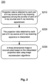
- Fig. 2 illustrates a flowchart of a method 200 for reconstructing a three-dimensional image from projection data obtained by a CT device according to the present disclosure.
- This method 200 is not encompassed by the wording of the claims but is considered as useful for understanding the invention.
- the CT device is not limited to the spiral CT device described in the embodiments of the present disclosure (as described above with reference to Fig. 1 ) as long as the CT device comprises a plurality of pairs of X-ray sources and X-ray receiving apparatuses.
- the spiral CT device shown in Fig. 1 will be taken as an example.
- a three-dimensional image is reconstructed using an image reconstruction algorithm, for example, reconstruction methods such as the Filtered Back Projection (FBP) reconstruction method, or the iterative Ordered Subset maximum Expectation Method (OSEM) or the Algebraic Reconstruction Technique (ART) in combination with the FBP algorithm etc.
- FBP Filtered Back Projection
- OSEM iterative Ordered Subset maximum Expectation Method
- ART Algebraic Reconstruction Technique
- data in the overlapping region is processed using a compressive sensing technique.
- Fig. 1 by taking the case shown in Fig. 1 as an example, if a plurality of rows of detectors are used as the X-ray receiving apparatuses 140, since the X-ray sources 130 have a certain size, two target points may not completely coincide. In order to completely cover the object to be inspected with the rays, it may inevitably enable partial overlapping of the X-ray receiving apparatuses 140-1 and 140-2 (as shown in Fig. 1 ). Conventional image reconstruction algorithms (for example, the FBP) cannot be used for overlapping data in this partial overlapping region.
- Conventional image reconstruction algorithms for example, the FBP
- the overlapping projection data may be regarded as a sum of a plurality of exponential functions, and cannot be expanded "in a non-destructive manner" to a linear function with a limited length; and secondly, if the object to be inspected is discretized, the overlapping projection data makes the imaging system underdetermined, which results in failure in acquisition of a correct solution.
- certain processing such as the compressive sensing technique described above, is required to be used. Under conditions that data sparsity is satisfied and random sampling is implemented, image quality may be recovered using a sampling frequency much less than an Nyquist sampling frequency.
- the image to be reconstructed may firstly be converted into a gradient image, and then an I 1 mode of the gradient image is minimized.
- the image reconstruction process is transformed into a nonlinear optimization problem under constraint conditions, which may be solved by the iterative reconstruction algorithm, the gradient descent method or the convex set mapping method etc.
- Fig. 2 illustrates a flowchart of a method 200 for reconstructing a three-dimensional image from projection data obtained by a CT device according to an embodiment of the present disclosure.
- the CT device is not limited to the spiral CT device described in the embodiments of the present disclosure (as described above with reference to Fig. 1 ) as long as the CT device comprises a plurality of pairs of X-ray sources and X-ray receiving apparatuses.
- the spiral CT device shown in Fig. 1 will be taken as an example.
- the method 200 starts at step S210, in which corresponding projection data is obtained by each pair of X-ray source and X-ray receiving apparatus among the plurality of pairs of X-ray sources and X-ray receiving apparatuses. Then, in step S220, the projection data obtained by each pair of X-ray source and X-ray receiving apparatus is interpolated. Finally, in step S230, a three-dimensional image is reconstructed based on the interpolated projection data using image reconstruction algorithms.
- step S230 for two pairs of X-ray sources and X-ray receiving apparatuses having an overlapped projection portion, an image reconstruction algorithm for data corresponding to the overlapped projection portion in the interpolated projection data obtained using the two pairs of X-ray sources and X-ray receiving apparatuses is different from an image reconstruction algorithm for data corresponding to remaining portions except for the overlapped projection portion in the interpolated projection data.
- step S210 corresponding projection data is obtained by each pair of X-ray source and X-ray receiving apparatus among the plurality of pairs of X-ray sources and X-ray receiving apparatuses.
- the X-ray sources 130-1 and 130-2 emit X-rays respectively
- the X-ray receiving apparatuses 140-1 and 140-2 receive the X-rays passing through the object to be inspected respectively, to obtain corresponding projection data respectively.
- the X-ray sources 130-1 and 130-2 emit X-rays respectively
- the X-ray receiving apparatuses 140-1 and 140-2 receive the X-rays passing through the object to be inspected respectively, to obtain corresponding projection data respectively.
- the X-ray receiving apparatuses 140-1 and 140-2 receive the X-rays passing through the object to be inspected respectively, to obtain corresponding projection data respectively.
- the X-ray receiving apparatuses 140-1 and 140-2 receive the X-rays passing through the object to be inspected respectively, to obtain corresponding projection data respectively.
- the two X-ray sources 130-1 and 130-2 have a coverage including the entire inspection space (this is true not only in a dimension corresponding to the paper sheets, but also in various slices distributed in a direction perpendicular to the paper sheets).
- the reproduction of the three-dimensional image of the object to be inspected may be realized using data obtained using the X-ray sources 130-1 and 130-2 and the X-ray receiving apparatuses 140-1 and 140-2.
- step S220 the projection data obtained using each pair of X-ray source and X-ray receiving apparatus is interpolated.
- the interpolation step is implemented using linear interpolation. Still
- the spiral CT device shown in Fig. 1 as an example, since projection data in a slice depending on any of the scanning axes is incomplete, it is necessary to fill blank regions between existing data using the existing data through interpolation to avoid volume artifacts from occurring during reconstruction.
- the exemplary interpolation method has been described in the description of Fig. 1 , and details thereof will not be described herein again.
- the projection data enriched by interpolation will be used for reconstruction in a next step.
- step S230 a three-dimensional image is reconstructed based on the interpolated projection data using image reconstruction algorithms.
- the image reconstruction algorithms may be conventional image reconstruction algorithms, for example, the FBP.
- an algorithm for example, the compressive sensing technique
- the exemplary algorithm for the overlapping region has been described above with respect to Fig. 1 and will not be described again here.
Landscapes
- Physics & Mathematics (AREA)
- Life Sciences & Earth Sciences (AREA)
- General Physics & Mathematics (AREA)
- Health & Medical Sciences (AREA)
- High Energy & Nuclear Physics (AREA)
- Geophysics (AREA)
- General Life Sciences & Earth Sciences (AREA)
- General Health & Medical Sciences (AREA)
- Nuclear Medicine, Radiotherapy & Molecular Imaging (AREA)
- Radiology & Medical Imaging (AREA)
- Theoretical Computer Science (AREA)
- Biochemistry (AREA)
- Analytical Chemistry (AREA)
- Immunology (AREA)
- Pathology (AREA)
- Chemical & Material Sciences (AREA)
- Pulmonology (AREA)
- Engineering & Computer Science (AREA)
- Molecular Biology (AREA)
- Spectroscopy & Molecular Physics (AREA)
- Apparatus For Radiation Diagnosis (AREA)
- Analysing Materials By The Use Of Radiation (AREA)
Description
- This application claims priority to the
Chinese Patent Application No. 201611117356.9, filed on December 7, 2016 - The present invention relates to the field of radiation imaging, and more particularly, to a spiral Computed Tomography (CT) device.
- With the development of the world economy and international trade, transportation of containers has been more and more widely applied in various countries' economies. At the same time, security inspection of the containers has also become more important. Especially after the "911" incident in 2001, countries around the world have strengthened security inspection against terrorist attacks, drug trafficking, smuggling, etc., and have enhanced inspection standards. Among the several common inspection methods in the field of security inspection, X-ray transmission technology has advantages such as strong penetration ability, short measurement time and high resolution, and therefore is often used for inspection of cargos in containers in airports, customs etc. However, with the improvement of social needs and the development of technology, CT technology has also been introduced into the field of social public security from initial medical diagnosis and industrial non-destructive testing.
- After the development for many years, the CT technology has gradually evolved from scanning using a thin X-ray beam, a small fan beam, or a large fan beam to scanning using spiral CT. The difference from the initial normal CT technology is in that, during scanning with the spiral CT, both a scanning bracket and an object to be detected are continuously moved, an X-ray source is spirally rotated relative to the object, and detectors continuously collect projection data, so as to obtain a three-dimensional image of the object to be detected, which may greatly shorten time for scanning. In addition, a resolution capability of the CT technology itself for densities and atomic numbers may further improve effects of material recognition during inspection.
- In 1991, the Elscint company firstly introduced dual-slice spiral CT technology. Then, other companies have also developed multi-slice spiral CT technology. In this multi-slice spiral CT technology, a structure of multiple rows of detectors is used to obtain projection data in multiple slices simultaneously during scanning in a circle, thereby increasing a detection area, obtaining a high-quality three-dimensional reconstructed image, and also improving the scanning efficiency of the system. The conventional multi-slice spiral CT has been widely used in the medical field etc., but cannot be well applied to inspection of large objects such as air containers etc. Specifically, in consideration of inconsistency among dosages of fan-shaped X-ray beams, fan angles of the X-ray beams must be kept below a certain upper limit value. Therefore, in a case where a volume of a large object such as an air container etc. is much greater than that of an object to be detected in the medial field, a larger inspection space is required by the same multi-slice spiral CT device in order to realize detection of the air container. In addition, a penetration power of an X-ray source is also a factor which must be considered, and complex structures of the X-ray source and detectors as well as stability problems caused by load-carrying also cannot be ignored.
- Therefore, there is a need for a spiral CT device capable of performing inspection of a large object with good performance.
- The International Application No.
PCT/IL00/00610 CN 102 697 517 A relates to a spiral CT scanner. - In order to solve the above problems existing in the conventional art, the present disclosure proposes a spiral CT device. The invention is defined by the appended claims.
- According to an aspect of the present disclosure, there is proposed a spiral CT device according to claim 1.
- In one embodiment, the inspection station is movable in the first direction and/or in a direction perpendicular to the first direction.
- In one embodiment, the first direction is a vertical direction.
- In one embodiment, the rotation supporting apparatus is a slip ring, the plurality of X-ray sources and the plurality of X-ray receiving apparatuses are disposed on a circumference of the slip ring, and one of the X-ray sources and a corresponding one of the X-ray receiving apparatuses are located on opposite sides of the circumference with respect to a center thereof.
- In one embodiment, in the detection state, a center of the circumference of the slip ring coincides with a center of the inspection space.
- In one embodiment, the rotational supporting apparatus is a bracket.
- According to the invention, the X-ray sources are X-ray accelerators.
- According to the invention, the X-ray sources provide fan-shaped X-ray beams.
- According to the invention, the plurality of X-ray sources are closely disposed on the rotational supporting apparatus, and the fan-shaped X-ray beams provided by the plurality of X-ray sources cover the inspection space with a minimum degree of overlapping.
- In one embodiment, the X-ray receiving apparatuses each comprise a plurality of rows of detectors.
- In one embodiment, the spiral CT device further comprises a processor. The processor is connected to the plurality of X-ray receiving apparatuses and configured to process the collected X-rays and reconstruct a three-dimensional image of the object to be inspected,
wherein the three-dimensional image is reconstructed by the processor using a linear interpolation method. - In one embodiment, when two adjacent ones of the plurality of X-ray receiving apparatuses have an overlapped coverage, data in the overlapping region is processed using a compressive sensing technique.
- With the spiral CT device according to the present disclosure, large objects may be inspected while ensuring a small system size, a short inspection time, and a high inspection quality. Thereby, the problems in the conventional techniques described above are solved, thereby satisfying the needs of airports for inspection of large cargos.
-
-
Fig. 1 illustrates a structural diagram of a spiral CT device according to an embodiment of the present disclosure. -
Fig. 2 illustrates a flowchart of a three-dimensional image reconstruction method according to the present disclosure. -
Fig. 3 illustrates an exemplary flowchart of a three-dimensional image reconstruction method implemented based on the spiral CT device shown inFig. 1 . - The specific embodiments of the present disclosure will be described in detail below. It should be noted that the embodiments herein are used for illustration only, without limiting the present disclosure. In the description below, a number of specific details are explained to provide better understanding of the present disclosure. In other instances, well known circuits, materials or methods are not described specifically so as not to obscure the present disclosure.
- The present disclosure will be described in detail below with reference to the accompanying drawings.
- Firstly,
Fig. 1 illustrates a structural diagram of aspiral CT device 100 according to an embodiment of the present disclosure. As shown, thespiral CT device 100 illustrated comprises aninspection station 110, a rotational supportingapparatus 120, two X-ray sources 130-1 and 130-2 (collectively referred to as 130 hereinafter), and two X-ray receiving apparatuses 140-1 and 140-2 (collectively referred to as 140 hereinafter). It is to be illustrated that, for convenience of description, only two X-ray sources 130 and two X-ray receiving apparatuses 140 are exemplarily shown inFig. 1 . It should be understood that in other embodiments of the present disclosure, more or less X-ray sources 130 and X-ray receiving apparatuses 140 may be included. - The
inspection station 110 is configured to carry an object to be inspected. Theinspection station 110 defines an inspection space which is located above the inspection station and is used for accommodating the object to be inspected. In one embodiment, theinspection space 150 may be physically defined by a physical component (for example, a wall panel built on the inspection station 110) or defined by other technical means (for example, infrared detection) in an auxiliary manner. Alternatively, theinspection space 150 may also be defined without any physical components, but instead it is agreed that there is a space of a particular size above theinspection station 110. - In one embodiment, the
inspection station 110 is movable in a first direction and/or in a direction perpendicular to the first direction. The movement in the first direction makes it convenient to place the object to be inspected. For example, theinspection station 110 is firstly brought down to a suitable height, and after the object to be inspected is placed on theinspection station 110, theinspection station 110 is raised to a height suitable for CT measurement. The movement in the direction perpendicular to the first direction makes it convenient to perform the spiral CT inspection, and a speed of the horizontal movement may be determined by a rotation period and a measurement length. - In one embodiment, the first direction is a vertical direction (as shown in
Fig. 1 ). - In a detection state, the
inspection station 110 is rotatable in the direction (as indicated by the horizontal direction inFig. 1 ) perpendicular to the first direction, so that theinspection station 110 cooperatively rotates with the rotational supportingapparatus 120 described below to realize helical scanning of the object to be inspected. - The rotational supporting
apparatus 120 is shown as a ring inFig. 1 . It may be seen that the rotational supportingapparatus 120 is shown as a slip ring inFig. 1 . However, it should be understood that in other embodiments of the - The X-ray sources 130 are located on the rotational supporting
apparatus 120 and are configured to transmit X-rays to pass through theinspection space 150. - The X-ray sources 130 are X-ray accelerators for providing high-energy X-ray beams.
- The X-ray sources 130 provide fan-shaped X-ray beams.
- The X-ray sources 130-1 and 130-2 are closely disposed on the rotational supporting apparatus, and the fan-shaped X-ray beams provided by the X-ray sources cover the
inspection space 150 with a minimal degree of overlapping. In this way, a size of the system may be better reduced. - A case where the two X-ray sources 130-1 and 130-2 are closely disposed is exemplarily shown in
Fig. 1 . A distance SO from a target point of one of the X-ray source(s) 130 to a central point of the inspection space 150 (i.e., a rotational radius of the target point of the X-ray source 130) is:
Fig. 1 , θ is a fan angle of an X-ray beam of the X-ray source 130, and n is a number of the X-ray source(s) 130 used. By taking θ = θmax = 45° as an example, when a single X-ray source 130 is used, SO1S = R/sin(22.5°); and when two X-ray sources 130 which are closely disposed are used under the same conditions, SO2S = R/sin(45°). Thus, SO1S /SO2S = 1.848, that is, the rotational radius of the target point when two X-ray sources 130 are used is 1/1.848 times the rotational radius of the target point in a case where a single X-ray source 130 is used. Therefore, when a plurality of X-ray sources are used, the rotational radius SO of the target point of each of the X-ray sources is effectively decreased, thereby reducing the size of the system. - In order to ensure that the system collects a sufficient amount of data and condition where rays which are emitted by an /th X-ray source and received by an m th detector at an r th projection angle interact with the object to be inspected, and generally refers to a length of a line of intersection between a corresponding pixel and the X-rays.
- For a sparse image, the image to be reconstructed may firstly be converted into a gradient image, and then an I 1 mode of the gradient image is minimized. In this way, the image reconstruction process is transformed into a nonlinear optimization problem under constraint conditions, which may be solved by the iterative reconstruction algorithm, the gradient descent method or the convex set mapping method etc.
-
Fig. 2 illustrates a flowchart of amethod 200 for reconstructing a three-dimensional image from projection data obtained by a CT device according to the present disclosure. Thismethod 200 is not encompassed by the wording of the claims but is considered as useful for understanding the invention. The CT device is not limited to the spiral CT device described in the embodiments of the present disclosure (as described above with reference toFig. 1 ) as long as the CT device comprises a plurality of pairs of X-ray sources and X-ray receiving apparatuses. Hereinafter, for the convenience of description, when themethod 200 is described in detail, the spiral CT device shown inFig. 1 will be taken as an example. - Specifically, the
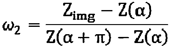
method 200 starts at step S210, in which corresponding projection data is obtained by each pair of X-ray source and X-ray receiving apparatus among the plurality of pairs of X-ray sources and X-ray receiving apparatuses. Then, in step S220, the projection data obtained by each pair of X-ray source and X-ray receiving apparatus is interpolated. Finally, in step S230, a three-dimensional image is reconstructed based on the interpolated projection data using image reconstruction algorithms. Here, in step S230, for two pairs of X-ray sources and X-ray receiving apparatuses having an overlapped projection portion, an image reconstruction algorithm for data corresponding to the overlapped projection portion in the interpolated projection data obtained using the two pairs of X-ray sources and X-ray receiving apparatuses is different from direction in which the inspection station horizontally moves) interpolation, for example, a 180-degree or 360-degree linear interpolation method, needs to be used. By taking the most commonly-used 180-degree linear interpolation method as an example, assuming that an interpolation position is Zimg, a data collection position is Z(α), and a position from the sampling point by 180° is Z(α+π), then projection data obtained after the 180-degree linear interpolation is:

- After linear interpolation of the projection data, a three-dimensional image is reconstructed using an image reconstruction algorithm, for example, reconstruction methods such as the Filtered Back Projection (FBP) reconstruction method, or the iterative Ordered Subset maximum Expectation Method (OSEM) or the Algebraic Reconstruction Technique (ART) in combination with the FBP algorithm etc.
- In one embodiment, when two adjacent ones (for example, the X-ray receiving apparatuses 140-1 and 140-2 in
Fig. 1 ) of the X-ray receiving apparatuses 140 have an overlapped coverage, data in the overlapping region is processed using a compressive sensing technique. - Specifically, by taking the case shown in
Fig. 1 as an example, if a plurality of rows of detectors are used as the X-ray receiving apparatuses 140, since the X-ray sources 130 have a certain size, two target points may not completely coincide. In order to completely cover the object to be inspected with the rays, it may inevitably enable partial overlapping of the X-ray receiving apparatuses 140-1 and 140-2 (as shown inFig. 1 ). Conventional image reconstruction algorithms (for example, the FBP) cannot be used for overlapping data in this partial overlapping region. This is because firstly, when the X-rays are absorbed, an exponential decay law is followed, and the overlapping projection data may be regarded as a sum of a plurality of exponential functions, and cannot be expanded "in a non-destructive manner" to a linear function with a limited length; and secondly, if the object to be inspected is discretized, the overlapping projection data makes the imaging system underdetermined, which results in failure in acquisition of a correct solution. In this regard, certain processing, such as the compressive sensing technique described above, is required to be used. Under conditions that data sparsity is satisfied and random sampling is implemented, image quality may be recovered using a sampling frequency much less than an Nyquist sampling frequency. Since the original image is sparse, the projection data may be expressed as:
- For a sparse image, the image to be reconstructed may firstly be converted into a gradient image, and then an I 1 mode of the gradient image is minimized. In this way, the image reconstruction process is transformed into a nonlinear optimization problem under constraint conditions, which may be solved by the iterative reconstruction algorithm, the gradient descent method or the convex set mapping method etc.
-
Fig. 2 illustrates a flowchart of amethod 200 for reconstructing a three-dimensional image from projection data obtained by a CT device according to an embodiment of the present disclosure. The CT device is not limited to the spiral CT device described in the embodiments of the present disclosure (as described above with reference toFig. 1 ) as long as the CT device comprises a plurality of pairs of X-ray sources and X-ray receiving apparatuses. Hereinafter, for the convenience of description, when themethod 200 is described in detail, the spiral CT device shown inFig. 1 will be taken as an example. - Specifically, the
method 200 starts at step S210, in which corresponding projection data is obtained by each pair of X-ray source and X-ray receiving apparatus among the plurality of pairs of X-ray sources and X-ray receiving apparatuses. Then, in step S220, the projection data obtained by each pair of X-ray source and X-ray receiving apparatus is interpolated. Finally, in step S230, a three-dimensional image is reconstructed based on the interpolated projection data using image reconstruction algorithms. Here, in step S230, for two pairs of X-ray sources and X-ray receiving apparatuses having an overlapped projection portion, an image reconstruction algorithm for data corresponding to the overlapped projection portion in the interpolated projection data obtained using the two pairs of X-ray sources and X-ray receiving apparatuses is different from an image reconstruction algorithm for data corresponding to remaining portions except for the overlapped projection portion in the interpolated projection data. - In step S210, corresponding projection data is obtained by each pair of X-ray source and X-ray receiving apparatus among the plurality of pairs of X-ray sources and X-ray receiving apparatuses. By taking the
spiral CT structure 100 shown inFig. 1 as an example, the X-ray sources 130-1 and 130-2 emit X-rays respectively, and the X-ray receiving apparatuses 140-1 and 140-2 receive the X-rays passing through the object to be inspected respectively, to obtain corresponding projection data respectively. Preferably, as in the case shown inFig. 1 , the two X-ray sources 130-1 and 130-2 have a coverage including the entire inspection space (this is true not only in a dimension corresponding to the paper sheets, but also in various slices distributed in a direction perpendicular to the paper sheets). Thereby, the reproduction of the three-dimensional image of the object to be inspected may be realized using data obtained using the X-ray sources 130-1 and 130-2 and the X-ray receiving apparatuses 140-1 and 140-2. - In step S220, the projection data obtained using each pair of X-ray source and X-ray receiving apparatus is interpolated. In an example, the interpolation step is implemented using linear interpolation. Still By taking the spiral CT device shown in
Fig. 1 as an example, since projection data in a slice depending on any of the scanning axes is incomplete, it is necessary to fill blank regions between existing data using the existing data through interpolation to avoid volume artifacts from occurring during reconstruction. In the above description, the exemplary interpolation method has been described in the description ofFig. 1 , and details thereof will not be described herein again. - The projection data enriched by interpolation will be used for reconstruction in a next step.
- In step S230, a three-dimensional image is reconstructed based on the interpolated projection data using image reconstruction algorithms. Here, the image reconstruction algorithms may be conventional image reconstruction algorithms, for example, the FBP. However, it is necessary to consider that the projection of two pairs of adjacent X-ray sources and X-ray receiving apparatuses is likely to overlap, and the conventional image reconstruction algorithms are no longer applicable for the overlapping region, that is, an algorithm (for example, the compressive sensing technique) different from the conventional image reconstruction algorithms is required to be used for the overlapping region. The exemplary algorithm for the overlapping region has been described above with respect to
Fig. 1 and will not be described again here. - It should be understood that the
method 200 may further comprise other conventional steps included in conventional three-dimensional image reconstruction methods, such as image noise reduction and smoothing, image correction, artifact region reconstruction, etc. - For example,
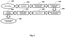
Fig. 3 illustrates a specific exemplary flowchart of a three-dimensional image reconstruction method 300 implemented based on the spiral CT device illustrated inFig. 1 . Of course, it should be understood that various steps inFig. 3 and an order of the steps are merely exemplary, and in other examples, other processing steps may be added or existing processing steps may be deleted, and the steps inFig. 3 may further be exchanged. - The exemplary three-dimensional image reconstruction flow illustrated in
Fig. 3 starts at data collection in step 310 and performspreliminary image reconstruction 330 through the interpolation 320 as described above. Next, the overlappingregion processing step 340 is performed as described above. It should be illustrated that although thepreliminary reconstruction 330 and theoverlapping region processing 340 are illustrated here as two separate steps, they may also be implemented as a single step, i.e., different processing is implemented for different portions (for example, like step S230 ofmethod 200 inFig. 2 ). - Then, the reconstruction flow further proceeds to image noise reduction and smoothing processing in step 350 to improve a signal to noise ratio.
- In
step 360, image correction is performed. The image correction comprises processes such as geometric correction, scatter correction, beam correction, detector gain correction, and metal artifact correction etc. In addition to the correction methods commonly used in X-ray inspection systems, the metal artifact correction is not negligible in inspection of containers. The most critical step in the metal artifact correction is to segment out a metal artifact region, that is, to determine a boundary of the metal artifact region, using the threshold method, clustering method, edge detection method, average method or region growth method etc. - In
step 370, the metal artifact region is reconstructed. Here, forward projection of the segmented region is performed to determine a position of a metal track in projection. Interpolation, for example, commonly-used linear interpolation, cubic spline interpolation, or fourth-order polynomial interpolation etc., is then performed to avoid, for example, striped artifacts, comet-like artifacts, etc. - In
step 380, a contrast enhancement process is performed on the preliminarily reconstructed image. - Finally, in step 390, a three-dimensional result is displayed in a form of a three-dimensional image or a two-dimensional cross-sectional view at a specific position etc.
- A typical example of inspection using the spiral CT device described in the present disclosure is given below:
- 1. Firstly, an inspection station is brought down to a certain height, an object to be inspected is placed on the inspection station, and then the inspection station is raised to a height for measurement, and is translated to a measurement region at a constant speed.
- 2. X-ray accelerators are used as ray sources to provide high-energy X-ray beams. After the accelerators are stabilized, X-rays are emitted by the accelerators at a certain frequency and are received by corresponding detectors. The accelerators and corresponding auxiliary devices are mounted on a slip ring or bracket and rotate synchronously with the detector apparatuses. In order to reduce a size of the system, multiple rows of accelerators which are closely disposed are used to increase a coverage space of the ray beams. In order to ensure that the system collects a sufficient amount of data and the inspection system is simplified to reduce a cost thereof, the accelerators should have a high beam emission frequency.
- 3. The detectors receive the X-ray beams passing through a container, and after a signal of the X-ray beams is converted, data of the signal is transmitted to a control center and data processing module. In the present disclosure, a structure of multiple rows of detectors is used, and image data in multiple slices may be obtained at the same time through exposure of the X-ray accelerators at a time, which may increase a detection area, reduce the collection time, and improve the inspection efficiency. Each of the X-ray accelerators corresponds to a group of multiple rows of detectors, and rotates around a rotational center at a constant speed on the slip ring. Numbers and sizes of detectors in various groups may be the same or different, and correspond to their respective data collection channels.
- 4. The control center controls operations of the X-ray emitting apparatuses, the detector apparatuses, the slip ring system, the inspection station and the data processing module, coordinates the entire inspection process through mechanical control, electrical control and security interlock control etc., and transmits the projection data to the data processing center for imaging. This part may be implemented using a single PC with a high performance, or a workstation or a cluster of machines.
- 5. The data processing center processes the projection data collected by the detectors and reconstructs a three-dimensional image of the object. This process comprises data interpolation preprocessing (for example, 180-degree or 360-degree linear interpolation), preliminary reconstruction of spiral CT images (using, for example, the FBP algorithm, ART algorithm or FBP-OSEM combined algorithm etc.), multi-source overlapping region processing, image correction, metal region reconstruction, image enhancement, etc.
- 6. Finally, a three-dimensional reconstruction image of the object in an air box to be inspected is displayed on a display. Three-dimensional rapid non-destructive inspection of the object to be inspected may be realized, which greatly improves the inspection efficiency to meet the needs of the airport for rapid inspection of a large number of cargoes.
Claims (9)
- A spiral Computed Tomography, CT, device for inspection of large cargos, comprising:an inspection station (110) operable to carry an object to be inspected on a carrying surface thereof, wherein an inspection space (150) is defined above the carrying surface, a normal direction for the carrying surface is a first direction, and the inspection station (110) is operable to move along a second direction perpendicular to the first direction to cause the object to be inspected to pass through the inspection space (150);a rotational supporting apparatus (120) disposed around the inspection space in a plane perpendicular to the second direction and operable to rotate around the inspection space (150); characterized in that the spiral CT device further comprisesa plurality of X-ray accelerators (130-1, 130-2) located on the rotational supporting apparatus (120) and configured to transmit X-rays to pass through the inspection space (150); anda plurality of X-ray receiving apparatuses (140-1, 140-2) in one-to-one correspondence to the plurality of X-ray accelerators, the plurality of X-ray receiving apparatuses (140-1, 140-2) being located on the rotational supporting apparatus (120) and opposing to the plurality of X-ray accelerators (130-1, 130-2) respectively, the plurality of X-ray receiving apparatuses (140-1, 140-2) being configured to collect the X-rays passing through the inspection space (150),wherein the plurality of X-ray accelerators (130-1, 130-2) and the plurality of X-ray receiving apparatuses (140-1, 140-2) are operable to rotate with the rotational supporting apparatus (120);wherein the plurality of X-ray accelerators (130-1, 130-2) are closely disposed on the rotational supporting apparatus (120), and fan-shaped X-ray beams provided by the plurality of X-ray accelerators (130-1, 130-2) cover the inspection space (150) with a minimum degree of overlapping.
- The spiral CT device according to claim 1, wherein the inspection station (110) is further movable along the first direction.
- The spiral CT device according to claim 2, wherein the first direction is a vertical direction.
- The spiral CT device according to claim 1, wherein the rotation supporting apparatus (120) is a slip ring, the plurality of X-ray accelerators (130-1, 130-2) and the plurality of X-ray receiving apparatuses (140-1, 140-2) are disposed on a circumference of the slip ring, and an X-ray accelerator (130) and a corresponding X-ray receiving apparatus (140) are disposed on opposite sides of the circumference with respect to a center of the circumference.
- The spiral CT device according to claim 4, wherein the center of the circumference of the slip ring coincides with a center of the inspection space (150) in the detection state.
- The spiral CT device according to claim 1, wherein the rotational supporting apparatus (120) is a bracket.
- The spiral CT device according to claim 1, wherein the X-ray receiving apparatuses (140-1, 140-2) each comprise a plurality of rows of detectors.
- The spiral CT device according to claim 1, further comprising: a processor connected to the plurality of X-ray receiving apparatuses (140-1, 140-2) and configured to process signals of the collected X-rays and reconstruct a three-dimensional image of the object to be inspected,
wherein the processor is configured to reconstruct the three-dimensional image using a linear interpolation method. - The spiral CT device according to claim 8, wherein when coverages of two adjacent X-ray receiving apparatuses of the plurality of X-ray receiving apparatuses (140-1, 140-2) have an overlapped region, signals in the overlapping region is processed using a compressive sensing technique.
Applications Claiming Priority (2)
| Application Number | Priority Date | Filing Date | Title |
|---|---|---|---|
| CN201611117356.9A CN106526686B (en) | 2016-12-07 | 2016-12-07 | Spiral CT equipment and three-dimensional image reconstruction method |
| PCT/CN2017/096017 WO2018103355A1 (en) | 2016-12-07 | 2017-08-04 | Spiral ct device and three-dimensional image reconstruction method |
Publications (3)
| Publication Number | Publication Date |
|---|---|
| EP3553569A1 EP3553569A1 (en) | 2019-10-16 |
| EP3553569A4 EP3553569A4 (en) | 2020-08-12 |
| EP3553569B1 true EP3553569B1 (en) | 2025-07-09 |
Family
ID=58341972
Family Applications (1)
| Application Number | Title | Priority Date | Filing Date |
|---|---|---|---|
| EP17879490.5A Active EP3553569B1 (en) | 2016-12-07 | 2017-08-04 | Spiral ct device and three-dimensional image reconstruction method |
Country Status (4)
| Country | Link |
|---|---|
| US (1) | US11346975B2 (en) |
| EP (1) | EP3553569B1 (en) |
| CN (1) | CN106526686B (en) |
| WO (1) | WO2018103355A1 (en) |
Families Citing this family (5)
| Publication number | Priority date | Publication date | Assignee | Title |
|---|---|---|---|---|
| CN106526686B (en) * | 2016-12-07 | 2019-05-07 | 同方威视技术股份有限公司 | Spiral CT equipment and three-dimensional image reconstruction method |
| DE102018201510A1 (en) | 2018-02-01 | 2019-08-01 | Robert Bosch Gmbh | Device for transmitting a signal by means of waveguides |
| CN112639532B (en) * | 2018-09-07 | 2024-09-06 | 深圳帧观德芯科技有限公司 | Image sensor with radiation detectors having different orientations |
| US11016042B2 (en) * | 2019-08-13 | 2021-05-25 | GE Sensing & Inspection Technologies, GmbH | Fast industrial computed tomography for large objects |
| JP7257924B2 (en) * | 2019-09-09 | 2023-04-14 | 株式会社ミツトヨ | Method for calibrating X-ray measuring device |
Family Cites Families (65)
| Publication number | Priority date | Publication date | Assignee | Title |
|---|---|---|---|---|
| US5805659A (en) * | 1996-09-30 | 1998-09-08 | Siemens Corporate Research, Inc. | Method and apparatus for spiral scan region of interest imaging |
| US6229870B1 (en) * | 1998-11-25 | 2001-05-08 | Picker International, Inc. | Multiple fan beam computed tomography system |
| DE60027930T2 (en) * | 2000-09-28 | 2007-01-25 | Koninklijke Philips Electronics N.V. | CT SCANNER WITH TIME COHERENT LARGE COVER |
| US6813374B1 (en) * | 2001-04-25 | 2004-11-02 | Analogic Corporation | Method and apparatus for automatic image quality assessment |
| US7103137B2 (en) * | 2002-07-24 | 2006-09-05 | Varian Medical Systems Technology, Inc. | Radiation scanning of objects for contraband |
| GB0309379D0 (en) * | 2003-04-25 | 2003-06-04 | Cxr Ltd | X-ray scanning |
| US8223919B2 (en) * | 2003-04-25 | 2012-07-17 | Rapiscan Systems, Inc. | X-ray tomographic inspection systems for the identification of specific target items |
| US8837669B2 (en) * | 2003-04-25 | 2014-09-16 | Rapiscan Systems, Inc. | X-ray scanning system |
| US7388941B2 (en) * | 2003-08-07 | 2008-06-17 | Xoran Technologies, Inc. | CT extremity scanner |
| US20050117700A1 (en) * | 2003-08-08 | 2005-06-02 | Peschmann Kristian R. | Methods and systems for the rapid detection of concealed objects |
| US7885375B2 (en) * | 2004-02-27 | 2011-02-08 | General Electric Company | Method and system for X-ray imaging |
| US7333587B2 (en) * | 2004-02-27 | 2008-02-19 | General Electric Company | Method and system for imaging using multiple offset X-ray emission points |
| WO2005119297A2 (en) * | 2004-05-27 | 2005-12-15 | L-3 Communications Security And Detection Systems, Inc. | Contraband detection systems using a large-angle cone beam ct system |
| CN101041989A (en) * | 2004-08-05 | 2007-09-26 | 邱则有 | Reinforced bar concrete solid load-carrying structural storied building cover |
| WO2006135837A1 (en) * | 2005-06-10 | 2006-12-21 | Xoran Technologies, Inc. | Multiple source ct scanner |
| CN100401983C (en) * | 2005-10-27 | 2008-07-16 | 上海交通大学 | Reconstruction method based on dual-source double-helix multi-slice helical CT |
| US7492860B2 (en) * | 2006-04-04 | 2009-02-17 | Ge Security, Inc. | Apparatus and method for controlling start and stop operations of a computed tomography imaging system |
| JP5214916B2 (en) * | 2006-07-19 | 2013-06-19 | 株式会社東芝 | X-ray CT apparatus and data processing method thereof |
| US20100183115A1 (en) * | 2006-08-11 | 2010-07-22 | Koninklijke Philips Electronics N.V. | System and method for acquiring image data |
| US7428292B2 (en) * | 2006-11-24 | 2008-09-23 | General Electric Company | Method and system for CT imaging using multi-spot emission sources |
| US7388940B1 (en) * | 2006-11-24 | 2008-06-17 | General Electric Company | Architectures for cardiac CT based on area x-ray sources |
| US7869561B2 (en) * | 2007-04-10 | 2011-01-11 | Arineta Ltd. | Cone-beam CT |
| CN100462051C (en) * | 2007-05-24 | 2009-02-18 | 上海交通大学 | Multi-source Helical CT Parallel Reconstruction System |
| CN101677796B (en) * | 2007-07-11 | 2011-06-08 | 株式会社岛津制作所 | Radiation image picking-up device |
| WO2009012453A1 (en) * | 2007-07-19 | 2009-01-22 | The University Of North Carolina At Chapel Hill | Stationary x-ray digital breast tomosynthesis systems and related methods |
| JP5179136B2 (en) * | 2007-10-02 | 2013-04-10 | ジーイー・メディカル・システムズ・グローバル・テクノロジー・カンパニー・エルエルシー | X-ray CT system |
| US8891726B2 (en) * | 2008-02-14 | 2014-11-18 | Koninklijke Philips N.V. | Multiple-source imaging system with flat-panel detector |
| JP5677301B2 (en) * | 2008-09-10 | 2015-02-25 | アナロジック コーポレーション | Computed tomography scanning system and method using multiple pixel x-ray sources |
| US8139709B2 (en) * | 2008-09-15 | 2012-03-20 | University Of Utah Research Foundation | Staggered circular scans for CT imaging |
| US8194821B2 (en) * | 2008-09-26 | 2012-06-05 | Varian Medical Systems, Inc. | Methods, systems, and computer-program products to correct degradation in tomographic images caused by extraneous radiation |
| US8862206B2 (en) * | 2009-11-12 | 2014-10-14 | Virginia Tech Intellectual Properties, Inc. | Extended interior methods and systems for spectral, optical, and photoacoustic imaging |
| DE102009057716A1 (en) * | 2009-12-10 | 2011-06-16 | Siemens Aktiengesellschaft | Method for reconstructing computer tomographic image data of patient, involves straightening projections under utilization of variable and/or weighting complementary projections under utilization of variable |
| US20110142201A1 (en) * | 2009-12-15 | 2011-06-16 | General Electric Company | Multi-view imaging system and method |
| US8270562B2 (en) * | 2009-12-21 | 2012-09-18 | General Electric Company | Multiple X-ray tube system and method of making same |
| JP5677738B2 (en) * | 2009-12-24 | 2015-02-25 | 株式会社東芝 | X-ray computed tomography system |
| CA2783485A1 (en) * | 2010-01-13 | 2011-07-21 | The Australian National University | A computed tomography imaging process and system |
| EP2537397B1 (en) * | 2010-02-16 | 2020-11-18 | Kristofer J. Roe | Adaptive modular cargo screening |
| US20130016805A1 (en) * | 2011-07-15 | 2013-01-17 | Toshiba Medical Systems Corporation | Method and system for acquiring sparse channel data and for image processing utilizing iterative reconstruction algorithms |
| KR101477543B1 (en) * | 2011-07-22 | 2014-12-31 | 삼성전자주식회사 | APPARATUS AND METHOD OF PHOTOGRAPHING USING X-ray |
| US9069092B2 (en) * | 2012-02-22 | 2015-06-30 | L-3 Communication Security and Detection Systems Corp. | X-ray imager with sparse detector array |
| DE102012204350B4 (en) * | 2012-03-20 | 2021-12-02 | Siemens Healthcare Gmbh | Method for energy calibration of quantum-counting X-ray detectors in a dual-source computer tomograph |
| WO2013184213A2 (en) * | 2012-05-14 | 2013-12-12 | The General Hospital Corporation | A distributed, field emission-based x-ray source for phase contrast imaging |
| CN102697517A (en) * | 2012-06-25 | 2012-10-03 | 苏州生物医学工程技术研究所 | Mobile computed tomography (CT) scanner and operation method thereof |
| US9417340B2 (en) * | 2012-07-06 | 2016-08-16 | Morpho Detection, Llc | Compact geometry CT system |
| CN102835971A (en) * | 2012-09-20 | 2012-12-26 | 苏州瑞派宁科技有限公司 | CT (computed tomography) scanning device, rotary CT system and examination method |
| CN103903303B (en) * | 2012-12-27 | 2018-01-30 | 清华大学 | Threedimensional model creation method and equipment |
| KR102090597B1 (en) * | 2012-12-28 | 2020-03-19 | 삼성전자주식회사 | X-ray imaging system and method for processing X-ray image |
| WO2014121039A1 (en) * | 2013-01-31 | 2014-08-07 | Duke University | System for improved compressive tomography and method therefor |
| US9778391B2 (en) * | 2013-03-15 | 2017-10-03 | Varex Imaging Corporation | Systems and methods for multi-view imaging and tomography |
| WO2015012850A1 (en) * | 2013-07-25 | 2015-01-29 | Analogic Corporation | Generation of diffraction signature of item within object |
| US10254436B2 (en) * | 2013-10-01 | 2019-04-09 | Voti Inc. | Scanning system, method, and corresponding bracket |
| CN104749197B (en) * | 2013-12-26 | 2017-08-11 | 清华大学 | CT system and its method |
| CN104374783B (en) * | 2013-12-26 | 2017-06-16 | 清华大学 | CT system and its method |
| CN104749648A (en) * | 2013-12-27 | 2015-07-01 | 清华大学 | Multi-energy spectrum static CT apparatus |
| DE102014200679A1 (en) * | 2014-01-16 | 2015-07-16 | Smiths Heimann Gmbh | Method and X-ray inspection system, in particular for nondestructive inspection of objects |
| US9865066B2 (en) * | 2014-05-06 | 2018-01-09 | Astrophysics Inc. | Computed tomography system for cargo and transported containers |
| CN105093342B (en) * | 2014-05-14 | 2017-11-17 | 同方威视技术股份有限公司 | Spiral ct system and method for reconstructing |
| US20160356915A1 (en) * | 2015-04-27 | 2016-12-08 | Christopher K. Green | Four plane x-ray inspection system |
| US10345479B2 (en) * | 2015-09-16 | 2019-07-09 | Rapiscan Systems, Inc. | Portable X-ray scanner |
| US10119923B2 (en) * | 2015-10-19 | 2018-11-06 | L3 Security & Detection Systems, Inc. | Systems and methods for image reconstruction at high computed tomography pitch |
| CN105784737B (en) * | 2016-03-29 | 2021-06-22 | 清华大学 | Container CT Inspection System |
| JP7097819B2 (en) * | 2016-05-13 | 2022-07-08 | コーニンクレッカ フィリップス エヌ ヴェ | Systems and methods for multi-beam X-ray exposure for 4D imaging |
| US20180038807A1 (en) * | 2016-08-08 | 2018-02-08 | Adaptix Ltd. | Method and system for reconstructing 3-dimensional images from spatially and temporally overlapping x-rays |
| CN206515487U (en) * | 2016-12-07 | 2017-09-22 | 同方威视技术股份有限公司 | Helical CT device |
| CN106526686B (en) * | 2016-12-07 | 2019-05-07 | 同方威视技术股份有限公司 | Spiral CT equipment and three-dimensional image reconstruction method |
-
2016
- 2016-12-07 CN CN201611117356.9A patent/CN106526686B/en active Active
-
2017
- 2017-08-04 WO PCT/CN2017/096017 patent/WO2018103355A1/en not_active Ceased
- 2017-08-04 US US16/467,140 patent/US11346975B2/en active Active
- 2017-08-04 EP EP17879490.5A patent/EP3553569B1/en active Active
Also Published As
| Publication number | Publication date |
|---|---|
| US11346975B2 (en) | 2022-05-31 |
| WO2018103355A1 (en) | 2018-06-14 |
| EP3553569A1 (en) | 2019-10-16 |
| CN106526686B (en) | 2019-05-07 |
| US20190317240A1 (en) | 2019-10-17 |
| EP3553569A4 (en) | 2020-08-12 |
| CN106526686A (en) | 2017-03-22 |
Similar Documents
| Publication | Publication Date | Title |
|---|---|---|
| EP2273257B1 (en) | Imaging system using a straight-line trajectory scan and method thereof | |
| EP3553569B1 (en) | Spiral ct device and three-dimensional image reconstruction method | |
| EP2942649B1 (en) | Computed tomography system for cargo and transported containers | |
| US7499522B2 (en) | Cargo security inspection system and method | |
| EP1953700B1 (en) | System and method for reconstructing an image by rectilinear trajectory scanning | |
| US7512213B2 (en) | Multiple-view-angle cargo security inspection method and system | |
| US8582857B2 (en) | Dual-energy material identification method and apparatus with undersampling | |
| US9466137B2 (en) | Spiral CT systems and reconstruction methods | |
| US20070116177A1 (en) | Imaging system | |
| CN101900694B (en) | System and method for dual-energy undersampling substance identification based on linear trajectory scanning | |
| CN105759319A (en) | Improved double-energy CT imaging method and apparatus | |
| US8456469B2 (en) | 3D reconstruction from oversampled 2D projections | |
| CN206515487U (en) | Helical CT device | |
| JP2026506443A (en) | CT scan imaging system and method with single linear scan tunnel | |
| US20090232277A1 (en) | System and method for inspection of items of interest in objects | |
| CN200956018Y (en) | Multi-vision aviation container safety inspection system | |
| CN121275808A (en) | Cone beam spiral CT system | |
| HK1115444B (en) | Multi-segment linear trace imaging cargo safety inspection system |
Legal Events
| Date | Code | Title | Description |
|---|---|---|---|
| STAA | Information on the status of an ep patent application or granted ep patent |
Free format text: STATUS: THE INTERNATIONAL PUBLICATION HAS BEEN MADE |
|
| PUAI | Public reference made under article 153(3) epc to a published international application that has entered the european phase |
Free format text: ORIGINAL CODE: 0009012 |
|
| STAA | Information on the status of an ep patent application or granted ep patent |
Free format text: STATUS: REQUEST FOR EXAMINATION WAS MADE |
|
| 17P | Request for examination filed |
Effective date: 20190614 |
|
| AK | Designated contracting states |
Kind code of ref document: A1 Designated state(s): AL AT BE BG CH CY CZ DE DK EE ES FI FR GB GR HR HU IE IS IT LI LT LU LV MC MK MT NL NO PL PT RO RS SE SI SK SM TR |
|
| AX | Request for extension of the european patent |
Extension state: BA ME |
|
| DAV | Request for validation of the european patent (deleted) | ||
| DAX | Request for extension of the european patent (deleted) | ||
| A4 | Supplementary search report drawn up and despatched |
Effective date: 20200709 |
|
| RIC1 | Information provided on ipc code assigned before grant |
Ipc: G01V 5/00 20060101AFI20200704BHEP Ipc: G01N 23/046 20180101ALI20200704BHEP |
|
| STAA | Information on the status of an ep patent application or granted ep patent |
Free format text: STATUS: EXAMINATION IS IN PROGRESS |
|
| 17Q | First examination report despatched |
Effective date: 20220330 |
|
| REG | Reference to a national code |
Ref legal event code: R079 Free format text: PREVIOUS MAIN CLASS: G01V0005000000 Ref country code: DE Ref document number: 602017090513 Country of ref document: DE Ipc: G01T0001290000 |
|
| GRAP | Despatch of communication of intention to grant a patent |
Free format text: ORIGINAL CODE: EPIDOSNIGR1 |
|
| STAA | Information on the status of an ep patent application or granted ep patent |
Free format text: STATUS: GRANT OF PATENT IS INTENDED |
|
| RIC1 | Information provided on ipc code assigned before grant |
Ipc: G01V 5/226 20240101ALI20250121BHEP Ipc: G01T 1/29 20060101AFI20250121BHEP |
|
| INTG | Intention to grant announced |
Effective date: 20250130 |
|
| GRAS | Grant fee paid |
Free format text: ORIGINAL CODE: EPIDOSNIGR3 |
|
| GRAA | (expected) grant |
Free format text: ORIGINAL CODE: 0009210 |
|
| STAA | Information on the status of an ep patent application or granted ep patent |
Free format text: STATUS: THE PATENT HAS BEEN GRANTED |
|
| AK | Designated contracting states |
Kind code of ref document: B1 Designated state(s): AL AT BE BG CH CY CZ DE DK EE ES FI FR GB GR HR HU IE IS IT LI LT LU LV MC MK MT NL NO PL PT RO RS SE SI SK SM TR |
|
| REG | Reference to a national code |
Ref country code: GB Ref legal event code: FG4D |
|
| REG | Reference to a national code |
Ref country code: CH Ref legal event code: EP |
|
| REG | Reference to a national code |
Ref country code: IE Ref legal event code: FG4D |
|
| REG | Reference to a national code |
Ref country code: DE Ref legal event code: R096 Ref document number: 602017090513 Country of ref document: DE |
|
| REG | Reference to a national code |
Ref country code: NL Ref legal event code: FP |
|
| PGFP | Annual fee paid to national office [announced via postgrant information from national office to epo] |
Ref country code: NL Payment date: 20250829 Year of fee payment: 9 |
|
| PGFP | Annual fee paid to national office [announced via postgrant information from national office to epo] |
Ref country code: DE Payment date: 20250916 Year of fee payment: 9 |
|
| PGFP | Annual fee paid to national office [announced via postgrant information from national office to epo] |
Ref country code: GB Payment date: 20250919 Year of fee payment: 9 |
|
| PG25 | Lapsed in a contracting state [announced via postgrant information from national office to epo] |
Ref country code: PT Free format text: LAPSE BECAUSE OF FAILURE TO SUBMIT A TRANSLATION OF THE DESCRIPTION OR TO PAY THE FEE WITHIN THE PRESCRIBED TIME-LIMIT Effective date: 20251110 |
|
| REG | Reference to a national code |
Ref country code: AT Ref legal event code: MK05 Ref document number: 1812323 Country of ref document: AT Kind code of ref document: T Effective date: 20250709 |
|
| PG25 | Lapsed in a contracting state [announced via postgrant information from national office to epo] |
Ref country code: IS Free format text: LAPSE BECAUSE OF FAILURE TO SUBMIT A TRANSLATION OF THE DESCRIPTION OR TO PAY THE FEE WITHIN THE PRESCRIBED TIME-LIMIT Effective date: 20251109 |
|
| PG25 | Lapsed in a contracting state [announced via postgrant information from national office to epo] |
Ref country code: NO Free format text: LAPSE BECAUSE OF FAILURE TO SUBMIT A TRANSLATION OF THE DESCRIPTION OR TO PAY THE FEE WITHIN THE PRESCRIBED TIME-LIMIT Effective date: 20251009 |
|
| REG | Reference to a national code |
Ref country code: LT Ref legal event code: MG9D |
|
| PG25 | Lapsed in a contracting state [announced via postgrant information from national office to epo] |
Ref country code: AT Free format text: LAPSE BECAUSE OF FAILURE TO SUBMIT A TRANSLATION OF THE DESCRIPTION OR TO PAY THE FEE WITHIN THE PRESCRIBED TIME-LIMIT Effective date: 20250709 |
|
| PG25 | Lapsed in a contracting state [announced via postgrant information from national office to epo] |
Ref country code: FI Free format text: LAPSE BECAUSE OF FAILURE TO SUBMIT A TRANSLATION OF THE DESCRIPTION OR TO PAY THE FEE WITHIN THE PRESCRIBED TIME-LIMIT Effective date: 20250709 |
|
| PG25 | Lapsed in a contracting state [announced via postgrant information from national office to epo] |
Ref country code: HR Free format text: LAPSE BECAUSE OF FAILURE TO SUBMIT A TRANSLATION OF THE DESCRIPTION OR TO PAY THE FEE WITHIN THE PRESCRIBED TIME-LIMIT Effective date: 20250709 |
|
| PG25 | Lapsed in a contracting state [announced via postgrant information from national office to epo] |
Ref country code: GR Free format text: LAPSE BECAUSE OF FAILURE TO SUBMIT A TRANSLATION OF THE DESCRIPTION OR TO PAY THE FEE WITHIN THE PRESCRIBED TIME-LIMIT Effective date: 20251010 |
|
| PG25 | Lapsed in a contracting state [announced via postgrant information from national office to epo] |
Ref country code: SE Free format text: LAPSE BECAUSE OF FAILURE TO SUBMIT A TRANSLATION OF THE DESCRIPTION OR TO PAY THE FEE WITHIN THE PRESCRIBED TIME-LIMIT Effective date: 20250709 |
|
| PG25 | Lapsed in a contracting state [announced via postgrant information from national office to epo] |
Ref country code: LV Free format text: LAPSE BECAUSE OF FAILURE TO SUBMIT A TRANSLATION OF THE DESCRIPTION OR TO PAY THE FEE WITHIN THE PRESCRIBED TIME-LIMIT Effective date: 20250709 |
|
| PG25 | Lapsed in a contracting state [announced via postgrant information from national office to epo] |
Ref country code: BG Free format text: LAPSE BECAUSE OF FAILURE TO SUBMIT A TRANSLATION OF THE DESCRIPTION OR TO PAY THE FEE WITHIN THE PRESCRIBED TIME-LIMIT Effective date: 20250709 Ref country code: PL Free format text: LAPSE BECAUSE OF FAILURE TO SUBMIT A TRANSLATION OF THE DESCRIPTION OR TO PAY THE FEE WITHIN THE PRESCRIBED TIME-LIMIT Effective date: 20250709 |
|
| PG25 | Lapsed in a contracting state [announced via postgrant information from national office to epo] |
Ref country code: RS Free format text: LAPSE BECAUSE OF FAILURE TO SUBMIT A TRANSLATION OF THE DESCRIPTION OR TO PAY THE FEE WITHIN THE PRESCRIBED TIME-LIMIT Effective date: 20251009 |
|
| PG25 | Lapsed in a contracting state [announced via postgrant information from national office to epo] |
Ref country code: ES Free format text: LAPSE BECAUSE OF FAILURE TO SUBMIT A TRANSLATION OF THE DESCRIPTION OR TO PAY THE FEE WITHIN THE PRESCRIBED TIME-LIMIT Effective date: 20250709 |
|
| PG25 | Lapsed in a contracting state [announced via postgrant information from national office to epo] |
Ref country code: RO Free format text: LAPSE BECAUSE OF FAILURE TO SUBMIT A TRANSLATION OF THE DESCRIPTION OR TO PAY THE FEE WITHIN THE PRESCRIBED TIME-LIMIT Effective date: 20250709 |