EP3553559A1 - Verfahren zur erkennung von objekten - Google Patents
Verfahren zur erkennung von objekten Download PDFInfo
- Publication number
- EP3553559A1 EP3553559A1 EP18166848.4A EP18166848A EP3553559A1 EP 3553559 A1 EP3553559 A1 EP 3553559A1 EP 18166848 A EP18166848 A EP 18166848A EP 3553559 A1 EP3553559 A1 EP 3553559A1
- Authority
- EP
- European Patent Office
- Prior art keywords
- doppler
- detections
- range
- axis
- accordance
- Prior art date
- Legal status (The legal status is an assumption and is not a legal conclusion. Google has not performed a legal analysis and makes no representation as to the accuracy of the status listed.)
- Granted
Links
Images


Classifications
-
- G—PHYSICS
- G01—MEASURING; TESTING
- G01S—RADIO DIRECTION-FINDING; RADIO NAVIGATION; DETERMINING DISTANCE OR VELOCITY BY USE OF RADIO WAVES; LOCATING OR PRESENCE-DETECTING BY USE OF THE REFLECTION OR RERADIATION OF RADIO WAVES; ANALOGOUS ARRANGEMENTS USING OTHER WAVES
- G01S13/00—Systems using the reflection or reradiation of radio waves, e.g. radar systems; Analogous systems using reflection or reradiation of waves whose nature or wavelength is irrelevant or unspecified
- G01S13/02—Systems using reflection of radio waves, e.g. primary radar systems; Analogous systems
- G01S13/50—Systems of measurement based on relative movement of target
- G01S13/58—Velocity or trajectory determination systems; Sense-of-movement determination systems
- G01S13/583—Velocity or trajectory determination systems; Sense-of-movement determination systems using transmission of continuous unmodulated waves, amplitude-, frequency-, or phase-modulated waves and based upon the Doppler effect resulting from movement of targets
- G01S13/584—Velocity or trajectory determination systems; Sense-of-movement determination systems using transmission of continuous unmodulated waves, amplitude-, frequency-, or phase-modulated waves and based upon the Doppler effect resulting from movement of targets adapted for simultaneous range and velocity measurements
-
- G—PHYSICS
- G01—MEASURING; TESTING
- G01S—RADIO DIRECTION-FINDING; RADIO NAVIGATION; DETERMINING DISTANCE OR VELOCITY BY USE OF RADIO WAVES; LOCATING OR PRESENCE-DETECTING BY USE OF THE REFLECTION OR RERADIATION OF RADIO WAVES; ANALOGOUS ARRANGEMENTS USING OTHER WAVES
- G01S13/00—Systems using the reflection or reradiation of radio waves, e.g. radar systems; Analogous systems using reflection or reradiation of waves whose nature or wavelength is irrelevant or unspecified
- G01S13/02—Systems using reflection of radio waves, e.g. primary radar systems; Analogous systems
- G01S13/50—Systems of measurement based on relative movement of target
- G01S13/505—Systems of measurement based on relative movement of target using Doppler effect for determining closest range to a target or corresponding time, e.g. miss-distance indicator
-
- G—PHYSICS
- G01—MEASURING; TESTING
- G01S—RADIO DIRECTION-FINDING; RADIO NAVIGATION; DETERMINING DISTANCE OR VELOCITY BY USE OF RADIO WAVES; LOCATING OR PRESENCE-DETECTING BY USE OF THE REFLECTION OR RERADIATION OF RADIO WAVES; ANALOGOUS ARRANGEMENTS USING OTHER WAVES
- G01S13/00—Systems using the reflection or reradiation of radio waves, e.g. radar systems; Analogous systems using reflection or reradiation of waves whose nature or wavelength is irrelevant or unspecified
- G01S13/66—Radar-tracking systems; Analogous systems
- G01S13/72—Radar-tracking systems; Analogous systems for two-dimensional [2D] tracking, e.g. combination of angle and range tracking, track-while-scan radar
- G01S13/723—Radar-tracking systems; Analogous systems for two-dimensional [2D] tracking, e.g. combination of angle and range tracking, track-while-scan radar by using numerical data
- G01S13/726—Multiple target tracking
-
- G—PHYSICS
- G01—MEASURING; TESTING
- G01S—RADIO DIRECTION-FINDING; RADIO NAVIGATION; DETERMINING DISTANCE OR VELOCITY BY USE OF RADIO WAVES; LOCATING OR PRESENCE-DETECTING BY USE OF THE REFLECTION OR RERADIATION OF RADIO WAVES; ANALOGOUS ARRANGEMENTS USING OTHER WAVES
- G01S13/00—Systems using the reflection or reradiation of radio waves, e.g. radar systems; Analogous systems using reflection or reradiation of waves whose nature or wavelength is irrelevant or unspecified
- G01S13/74—Systems using reradiation of radio waves, e.g. secondary radar systems; Analogous systems
-
- G—PHYSICS
- G01—MEASURING; TESTING
- G01S—RADIO DIRECTION-FINDING; RADIO NAVIGATION; DETERMINING DISTANCE OR VELOCITY BY USE OF RADIO WAVES; LOCATING OR PRESENCE-DETECTING BY USE OF THE REFLECTION OR RERADIATION OF RADIO WAVES; ANALOGOUS ARRANGEMENTS USING OTHER WAVES
- G01S13/00—Systems using the reflection or reradiation of radio waves, e.g. radar systems; Analogous systems using reflection or reradiation of waves whose nature or wavelength is irrelevant or unspecified
- G01S13/87—Combinations of radar systems, e.g. primary radar and secondary radar
- G01S13/872—Combinations of primary radar and secondary radar
-
- G—PHYSICS
- G01—MEASURING; TESTING
- G01S—RADIO DIRECTION-FINDING; RADIO NAVIGATION; DETERMINING DISTANCE OR VELOCITY BY USE OF RADIO WAVES; LOCATING OR PRESENCE-DETECTING BY USE OF THE REFLECTION OR RERADIATION OF RADIO WAVES; ANALOGOUS ARRANGEMENTS USING OTHER WAVES
- G01S13/00—Systems using the reflection or reradiation of radio waves, e.g. radar systems; Analogous systems using reflection or reradiation of waves whose nature or wavelength is irrelevant or unspecified
- G01S13/88—Radar or analogous systems specially adapted for specific applications
- G01S13/89—Radar or analogous systems specially adapted for specific applications for mapping or imaging
-
- G—PHYSICS
- G01—MEASURING; TESTING
- G01S—RADIO DIRECTION-FINDING; RADIO NAVIGATION; DETERMINING DISTANCE OR VELOCITY BY USE OF RADIO WAVES; LOCATING OR PRESENCE-DETECTING BY USE OF THE REFLECTION OR RERADIATION OF RADIO WAVES; ANALOGOUS ARRANGEMENTS USING OTHER WAVES
- G01S13/00—Systems using the reflection or reradiation of radio waves, e.g. radar systems; Analogous systems using reflection or reradiation of waves whose nature or wavelength is irrelevant or unspecified
- G01S13/88—Radar or analogous systems specially adapted for specific applications
- G01S13/93—Radar or analogous systems specially adapted for specific applications for anti-collision purposes
- G01S13/931—Radar or analogous systems specially adapted for specific applications for anti-collision purposes of land vehicles
- G01S2013/9327—Sensor installation details
- G01S2013/93271—Sensor installation details in the front of the vehicles
-
- G—PHYSICS
- G01—MEASURING; TESTING
- G01S—RADIO DIRECTION-FINDING; RADIO NAVIGATION; DETERMINING DISTANCE OR VELOCITY BY USE OF RADIO WAVES; LOCATING OR PRESENCE-DETECTING BY USE OF THE REFLECTION OR RERADIATION OF RADIO WAVES; ANALOGOUS ARRANGEMENTS USING OTHER WAVES
- G01S13/00—Systems using the reflection or reradiation of radio waves, e.g. radar systems; Analogous systems using reflection or reradiation of waves whose nature or wavelength is irrelevant or unspecified
- G01S13/88—Radar or analogous systems specially adapted for specific applications
- G01S13/93—Radar or analogous systems specially adapted for specific applications for anti-collision purposes
- G01S13/931—Radar or analogous systems specially adapted for specific applications for anti-collision purposes of land vehicles
- G01S2013/9327—Sensor installation details
- G01S2013/93274—Sensor installation details on the side of the vehicles
Definitions
- the present invention relates to a method for the recognition of objects in a traffic space by means of a radar sensor system arranged at or in a host vehicle, comprising the steps:
- ADAS advanced driver assistance systems
- lane departure warning systems such as lane departure warning systems, lane change assistance systems, active brake assist systems and the like.
- Such systems generally require a reliable identification of objects such as obstacles, other vehicles or pedestrians present in the environment of the host vehicle.
- the recognition of stationary objects is of particular importance. In many applications, it is desired to find the boundaries of stationary objects. Based on the boundaries, a map of the observed traffic space can be generated.
- Radar sensor systems often use the known Doppler effect to gather information relating to objects moving relative to the host vehicle.
- the Doppler effect or Doppler shift is a change in frequency observed when a wave source moves relative to the receiver.
- a Range-Doppler-map can be generated more quickly and easily than a X-Y-map showing the actual positions of detected objects.
- radar sensor systems output frames or scans.
- a plurality of single detections can be identified.
- single detections are spot-like portions of the Range-Doppler-map which fulfill a predefined detection criterion. For example, pixels having intensity values above a threshold or defining a local maximum may constitute single detections.
- the shapes of the real objects may be approximated based on the single detections - for example by creating a polyline connecting the detections on the ground plane.
- the range and the observation angle can be computed for each of the detections.
- the calculation of the observation angle or azimuth, for example by means of an angle-finding process is rather complicated.
- the computational effort is rather high.
- the division of the Range-Doppler-map into evaluation regions enables a considerable reduction of the computational effort necessary for the determination of the object boundary, because angle calculations and the like only have to be carried out for a limited number of detections. Simultaneously, it is ensured that there is least one selected detection for each evaluation region and thus for each portion of the range axis or the Doppler axis. This means that the selected detections are distributed over a large section of the range axis or the Doppler axis, respectively. The reliability of the subsequent boundary recognition is thus enhanced.
- the separation lines can be called “fences", since they define a border of an area. Specifically, separation lines extending parallel to the range axis can be called “Doppler fences", whereas separation lines extending parallel to the Doppler axis can be called “range fences”.
- the boundary of the at least one object can be determined exclusively based on the selected detections.
- the remaining, i. e. non-selected detections can be discarded, at least for the purpose of determining the object boundary.
- the number of calculations is kept low.
- the boundary of the at least one object can be determined based on a combination of the selected detections with detections fulfilling a separate detection criterion.
- an observation angle between a current line of sight and a fixed reference axis, in particular a driving direction or a longitudinal axis of the host vehicle, can be computed for each of the selected detections.
- the line of sight extends from the object surface spot associated with the respective detection to an active region of the radar sensor system. If both the range and the observation angle are known for a specific detection, the position of the respective object surface spot in Cartesian coordinates can be indicated.
- the separation lines extend parallel to the range axis, wherein in step (v) a selected detection is determined which has, among the detections present in the respective evaluation region, the lowest range value. According to this embodiment, it is checked in step (v) which of the detections present in the respective evaluation region has the lowest range value. This check requires only little computational effort. The selection of the "closest" detections over an angular range enables an efficient determination of that surface portion of the object that at least essentially faces the radar sensor system.
- the separation lines extend parallel to the Doppler axis, wherein in step (v) a selected detection is determined which has, among the detections present in the respective evaluation region, the highest or lowest Doppler value. According to this embodiment, it is checked in step (v) which of the detections present in the respective evaluation region has the highest or the lowest Doppler value, which requires only little computational effort and enables an efficient determination of surface portions of the object extending at least essentially in the direction of propagation of the primary radar signal.
- step (v) a first selected detection is determined which has, among the detections present in the respective evaluation region, the highest Doppler value and a second selected detection is determined which has, among the detections present in the respective evaluation region, the lowest Doppler value.
- step (v) is carried out for a first set of evaluation regions separated by Doppler separation lines extending parallel to the range axis and subsequently for a second set of evaluation regions separated by range separation lines extending parallel to the Doppler axis, or vice versa.
- the range selection and the Doppler selection as described above can be combined to refine the selection process.
- a spread is defined based on the selected detections, wherein step (v) is carried out for the second set of evaluation regions only considering detections being outside the spread.
- the selection is first carried out based on Doppler fences. Then it is checked which of the selected detections has the lowest Doppler value and which of the selected detections has the highest Doppler value. The range between the lowest Doppler value and the highest Doppler value is defined as the Doppler spread. Subsequently, a selection is carried out based on range fences. However, only such selected detections are considered for further calculations that are located outside the spread. This procedure avoids the selection of ghost detections which are "behind" a front surface of the object.
- the field of view of the radar sensor system can be divided into field-of-view-regions and the evaluation regions can be defined by transforming the field-of-view-regions into the Range-Doppler-map.
- the evaluation regions can be defined by transforming the field-of-view-regions into the Range-Doppler-map.
- This enables an adequate division of the real world space of interest.
- only a region of the Range-Doppler-map is divided into evaluation regions, in particular a region which corresponds to the field of view of the radar sensor system.
- the field of view is the effective sensing region of the radar sensor system in a Cartesian coordinate system, ranging from a minimum angle to a maximum angle and from a minimum radius to a maximum radius.
- the field-of-view-regions can have the shape of, preferably regular, circular sectors. This corresponds to an angular division of the field of view.
- the field-of-view-regions can have the shape of annular sectors. This corresponds to a radial division of the field of view.
- step (iv) less than 15 separation lines, preferably 2 to 10 separation lines and more preferably 3 to 7 separation lines are defined to divide at least a region of the Range-Doppler map into a plurality of adjacent evaluation regions. It has turned out that such a number of evaluation regions is sufficient for a reliable boundary recognition.
- the invention also relates to a system for the recognition of objects in a traffic space comprising a radar sensor system for transmitting a primary radar signal into a traffic space and for receiving a secondary radar signal reflected by at least one object and an electronic processing unit for processing the secondary radar signal.
- the electronic processing unit is configured for carrying out a method in accordance with any one of the preceding claims.
- the electronic processing device may be united with the radar sensor system or configured as a separate unit.
- the electronic processing unit may comprise a computer.
- the radar sensor system is configured to be mounted to a side portion or a corner portion of the host vehicle.
- the invention further relates to a computer program product including executable program code which, when executed, carries out a method as disclosed above.
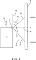
- a motor vehicle 11 also called a host vehicle
- a side-viewing radar sensor system 13 mounted to a front corner section of the motor vehicle 11.
- the radar sensor system 13 is preferably based on a millimeter wave radar sensor.
- a single channel radar sensor is preferred to minimize the production costs.
- a multiple channel radar sensor may be provided to enhance the detection performance.
- the radar sensor system 13 can be connected to an electronic processing device (not shown), for example an advanced emergency braking system, a pedestrian collision avoidance system or an autonomous driving system.
- the motor vehicle 11 is moving at a speed v in a driving direction 15.
- a stationary object 19 for example a wall, is located next to the motor vehicle 11.
- the stationary object 19 extends along the driving direction 15.
- Fig. 1 shows a situation where the motor vehicle 11 passes the stationary object 19.
- the radar sensor system 13 is configured for transmitting a primary radar signal into the traffic space 23 beside the motor vehicle 11 and for detecting stationary objects 19 present in the traffic space 23 on the basis of a secondary radar signal reflected by the stationary objects 19.
- a line 25 which extends from a specific spot of the stationary object 19 to the active region of the radar sensor system 13 is called a "line of sight".
- a Range-Doppler-map 30 as shown in Fig. 8 is generated.
- the Range-Doppler-map 30 has a range axis 31 representing the distance between the radar sensor system 13 and the respective surface spot and a Doppler axis 32 representing the relative Doppler shift of the secondary radar signal as reflected by the respective surface spot relative to the primary radar signal.
- the secondary radar signal is sampled in the time domain and then subjected to a Fast Fourier Transform (FFT).
- FFT Fast Fourier Transform
- the Range-Doppler-map 30 can refer to a single channel or the average, for example the average amplitude, of different channels.
- the Range-Doppler-map 30 can be a raw data output of a FFT with windowing or be based on an output which has been subjected to post-processing steps such as thresholding or other algorithms.
- Portions of the Range-Doppler-map 30 that fulfill a predefined detection criterion form single detections 35.
- a plurality of single detections 35 can be determined.
- detections 35 are shown which are determined by means of thresholding. It can be seen that most of the detections 35 are in the far range, while in the near range no detections are found.
- the field of view 37 of the radar sensor system 13 is divided into field-of-view-regions 39.
- the field-of-view-regions 39 are regular circular sectors.
- the borders separating the field-of-view-regions 39 are shown as dashed lines.
- the field-of-view-regions 39 are transformed into the Range-Doppler-space to generate evaluation regions 40 as shown in Fig. 3 .
- Doppler fences 41 Based on formulae (2) and (3), a series of vertical lines called Doppler fences 41 is generated.
- the evaluation regions 40 are separated by the Doppler fences 41.
- the first and the last evaluation region 40 are partly defined by a minimal Doppler value d min and a maximal Doppler value d max , respectively.
- each evaluation region 40 it is determined which of the detections 35 present in the respective evaluation region 40 has the lowest range value.
- This detection 35' shown as filled dot in Fig. 3 , is selected for further processing.
- a set 45 of selected detections 35' is generated. In this manner, the closest detections 35' corresponding to the closest boundary of the stationary object 19 are found.
- a common problem in radar sensor technology is the generation of ghost targets as a consequence of multi-path propagation.
- the closest detection 35' in a certain angle scope is likely to result from a reflection from the real object 19. Therefore, the selection of the closest detections 35' reduces or avoids the problem of ghost targets.
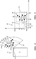
- Figs. 4 and 5 refer to an alternative embodiment of the invention.
- the borders separating the field-of-view-regions 39' are shown as dashed circular arcs.
- the field-of-view-regions 39' are transformed into the Range-Doppler-space to generate evaluation regions 40' as shown in Fig. 5 .
- range fences 51 Based on formula (4), a series of horizontal lines called range fences 51 is generated.
- the evaluation regions 40' are separated by the range fences 51.
- the first and the last evaluation region 40' are partly defined by a minimal range value r min and a maximal range value r max , respectively.
- each evaluation region 40' it is determined which of the detections 35 present in the respective evaluation region 40' has the lowest Doppler value and which of the detections 35 present in the respective evaluation region 40' has the highest Doppler value. These detections 35', shown as filled dots in Fig. 5 , are selected for further processing.
- the detections 35' having extremal Doppler values are related to the maximum and minimum observation angle ⁇ and thus to the contour of the stationary object 19.
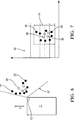
- the selection of detections 35' based on Doppler fences 41 according to Figs. 2 and 3 can be combined with a selection of detections 35' based on range fences 51 according to Figs. 4 and 5 to find more detections 35' related to the outer surface of the stationary object 19.
- the result of such a combined selection is shown in Figs. 6 and 7 .
- selected detections 35' are determined based on Doppler fences 41 as shown in Fig. 3 . Based on these detections, a Doppler spread ranging from d min to d max is defined. Then selected detections 35' are determined based on range fences 51 as shown in Fig. 5 . If the detections found in this step are outside the defined Doppler spread, they are used for further processing, otherwise they are removed from the list of selected detections 35'.
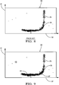
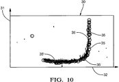
- Figs. 8-10 show Range-Doppler-maps 30 displaying the same secondary radar signal.
- detections 35 found by a conventional thresholding process are shown. In the low range region, no detections are present.
- detections 35' found by a method according to the invention using Doppler fences 41 as shown in Fig. 3 are indicated in addition to the detections 35 found by the conventional thresholding process. It can be seen that more detections 35, 35' in the near range are found.
- Fig. 10 detections 35' found by a method according to the invention using a combination of Doppler fences 41 as shown in Fig. 3 and range fences 51 as shown in Fig. 5 are indicated in addition to the detections 35 found by the conventional thresholding process. Compared to Fig. 9 , more detections 35, 35' in the far range are found.
- the boundary of the stationary object 19 in a vehicle coordinate system is determined.
- the observation angle ⁇ is computed for each of the selected detections 35', preferably by means of an angle-finding process.
- FIG. 11 detections 35 found by a conventional thresholding process are shown in a Cartesian coordinate system.
- the origin of the Cartesian coordinate system is located at the front bumper of the motor vehicle 11.
- Fig. 12 shows detections 35 found by the conventional thresholding process and in addition detections 35 found by a method in accordance with the invention.
- the boundary of the stationary object 19 is discernible more clearly, since more detections 35, 35' are present.
- the Doppler resolution can be intentionally reduced to get a signal having a higher level from the stationary object 19.
- An advantage of a method in accordance with the invention in comparison with a common contour extraction algorithm is a reduction of the number of detections 35 and thus a reduction of angle finding calculations.
- the Range-Doppler-map 30 does not present the actual physical shape of a stationary object 19, there can be an over-sampling or an under-sampling.
- the objects 19 on the sides of the motor vehicle 11 have a large Doppler spread even if they are positioned relatively close to the motor vehicle 11. This leads to an over-sampling of the Range-Doppler contour.
- the use of range fences 51 and/or Doppler fences 41 avoids such an undesired over-sampling.
- the invention thus enables a reliable recognition of stationary objects 19 by means of a radar sensor system 13 without the necessity to carry out a multitude of complex computations.
Landscapes
- Engineering & Computer Science (AREA)
- Remote Sensing (AREA)
- Radar, Positioning & Navigation (AREA)
- Physics & Mathematics (AREA)
- Computer Networks & Wireless Communication (AREA)
- General Physics & Mathematics (AREA)
- Electromagnetism (AREA)
- Radar Systems Or Details Thereof (AREA)
Priority Applications (3)
| Application Number | Priority Date | Filing Date | Title |
|---|---|---|---|
| EP18166848.4A EP3553559B1 (de) | 2018-04-11 | 2018-04-11 | Verfahren zur erkennung von objekten |
| US16/366,005 US11402486B2 (en) | 2018-04-11 | 2019-03-27 | Method for the recognition of objects |
| CN201910284838.0A CN110361740B (zh) | 2018-04-11 | 2019-04-10 | 识别对象的方法 |
Applications Claiming Priority (1)
| Application Number | Priority Date | Filing Date | Title |
|---|---|---|---|
| EP18166848.4A EP3553559B1 (de) | 2018-04-11 | 2018-04-11 | Verfahren zur erkennung von objekten |
Publications (2)
| Publication Number | Publication Date |
|---|---|
| EP3553559A1 true EP3553559A1 (de) | 2019-10-16 |
| EP3553559B1 EP3553559B1 (de) | 2022-06-01 |
Family
ID=61971972
Family Applications (1)
| Application Number | Title | Priority Date | Filing Date |
|---|---|---|---|
| EP18166848.4A Active EP3553559B1 (de) | 2018-04-11 | 2018-04-11 | Verfahren zur erkennung von objekten |
Country Status (3)
| Country | Link |
|---|---|
| US (1) | US11402486B2 (de) |
| EP (1) | EP3553559B1 (de) |
| CN (1) | CN110361740B (de) |
Cited By (1)
| Publication number | Priority date | Publication date | Assignee | Title |
|---|---|---|---|---|
| CN112073907A (zh) * | 2020-08-11 | 2020-12-11 | 陕西正马物流有限公司 | 粉煤灰运输车监控方法、装置、计算机设备及存储介质 |
Families Citing this family (5)
| Publication number | Priority date | Publication date | Assignee | Title |
|---|---|---|---|---|
| US11353578B2 (en) | 2019-02-28 | 2022-06-07 | Zoox, Inc. | Recognizing radar reflections using position information |
| US11255958B2 (en) * | 2019-02-28 | 2022-02-22 | Zoox, Inc. | Recognizing radar reflections using velocity information |
| KR102770456B1 (ko) * | 2019-12-16 | 2025-02-20 | 현대자동차주식회사 | 차량 센서 성능 평가 장치 및 그의 성능 평가 방법 |
| KR102332509B1 (ko) * | 2020-05-22 | 2021-11-29 | 현대모비스 주식회사 | 후방 교차 충돌 경고 방법 및 장치 |
| CN217945043U (zh) * | 2021-08-06 | 2022-12-02 | Aptiv技术有限公司 | 车辆和确定车辆周围的物体的设备 |
Citations (3)
| Publication number | Priority date | Publication date | Assignee | Title |
|---|---|---|---|---|
| DE102014218092A1 (de) * | 2014-09-10 | 2016-03-10 | Volkswagen Aktiengesellschaft | Erstellen eines Abbilds der Umgebung eines Kraftfahrzeugs und Bestimmen der relativen Geschwindigkeit zwischen dem Kraftfahrzeug und Objekten in der Umgebung |
| WO2017039862A1 (en) * | 2015-08-31 | 2017-03-09 | Autoliv Asp, Inc. | Apparatus and method for detecting blockage of an automotive radar sensor |
| US20170356991A1 (en) * | 2016-06-13 | 2017-12-14 | Panasonic Intellectual Property Management Co., Ltd. | Radar device and detection method |
Family Cites Families (48)
| Publication number | Priority date | Publication date | Assignee | Title |
|---|---|---|---|---|
| US4958638A (en) | 1988-06-30 | 1990-09-25 | Georgia Tech Research Corporation | Non-contact vital signs monitor |
| US5689268A (en) | 1996-08-02 | 1997-11-18 | Boeing North American, Inc. | Radar detection and classification of helicopters |
| US6653971B1 (en) | 1999-05-14 | 2003-11-25 | David L. Guice | Airborne biota monitoring and control system |
| US6121916A (en) | 1999-07-16 | 2000-09-19 | Eaton-Vorad Technologies, L.L.C. | Method and apparatus for recognizing stationary objects with a moving side-looking radar |
| US20020028003A1 (en) | 2000-03-27 | 2002-03-07 | Krebs David E. | Methods and systems for distinguishing individuals utilizing anatomy and gait parameters |
| US7016782B2 (en) | 2002-05-30 | 2006-03-21 | Delphi Technologies, Inc. | Collision detection system and method of estimating miss distance |
| US6674394B1 (en) | 2003-03-28 | 2004-01-06 | Visteon Global Technologies, Inc. | Method for determining object location from side-looking sensor data |
| JP4598653B2 (ja) * | 2005-05-13 | 2010-12-15 | 本田技研工業株式会社 | 衝突予知装置 |
| EP1887382A1 (de) * | 2005-05-19 | 2008-02-13 | Olympus Corporation | Distanzmessvorrichtung, distanzmessverfahren und distanzmessprogramm |
| US20100074379A1 (en) | 2008-04-01 | 2010-03-25 | Ming-Chiang Li | Tuning replica generation methods and apparatus for their most optimum performance in processing transient signals |
| CA2762762C (en) * | 2008-05-29 | 2017-11-28 | Cambridge Consultants Limited | Radar system and method |
| AT507035B1 (de) * | 2008-07-15 | 2020-07-15 | Airbus Defence & Space Gmbh | System und verfahren zur kollisionsvermeidung |
| US7791528B2 (en) * | 2008-11-24 | 2010-09-07 | Autoliv Asp, Inc. | Method and apparatus for radar signal processing |
| US20100286543A1 (en) | 2009-05-05 | 2010-11-11 | Siemens Medical Solutions Usa, Inc. | Automated Cardiac Status Determination System |
| US8529458B2 (en) | 2009-09-28 | 2013-09-10 | State Of Oregon By And Through The State Board Of Higher Education On Behalf Of Portland State University | Method and apparatus for assessment of fluid responsiveness |
| WO2011056730A2 (en) | 2009-11-03 | 2011-05-12 | Vawd Applied Science & Technology Corporation | Standoff range sense through obstruction radar system |
| DE112010005662T5 (de) | 2010-06-16 | 2013-03-21 | Toyota Jidosha Kabushiki Kaisha | Objektidentifikationsvorrichtung und Verfahren |
| DE102010062235A1 (de) | 2010-12-01 | 2012-06-06 | Robert Bosch Gmbh | Fahrerassistenzsystem zur Detektion eines Objekts in einer Fahrzeugumgebung |
| EP2589979A1 (de) | 2011-11-03 | 2013-05-08 | Thales Nederland B.V. | System zur Kennzeichnung der Bewegung eines Individuums, insbesondere eines menschlichen Individuums |
| US20200064444A1 (en) | 2015-07-17 | 2020-02-27 | Origin Wireless, Inc. | Method, apparatus, and system for human identification based on human radio biometric information |
| DE102012024999A1 (de) * | 2012-12-19 | 2014-06-26 | Valeo Schalter Und Sensoren Gmbh | Verfahren zum Einstellen einer Detektionsschwelle für ein Empfangssignal eines Frequenzmodulations-Dauerstrich-Radarsensors eines Kraftfahrzeugs abhängig vom Rauschpegel, Radarsensor und Kraftfahrzeug |
| GB2517710A (en) * | 2013-08-28 | 2015-03-04 | Aveillant Ltd | Radar system and associated apparatus and methods |
| US9255988B2 (en) * | 2014-01-16 | 2016-02-09 | GM Global Technology Operations LLC | Object fusion system of multiple radar imaging sensors |
| WO2015144741A1 (en) | 2014-03-27 | 2015-10-01 | Sony Corporation | Camera with radar system |
| US9746549B1 (en) * | 2014-07-11 | 2017-08-29 | Altera Corporation | Constant false alarm rate circuitry in adaptive target detection of radar systems |
| DE102014110667A1 (de) * | 2014-07-29 | 2016-02-04 | Valeo Schalter Und Sensoren Gmbh | Vefahren zum Klassifizieren eines Objektes in einem Umgebungsbereich eines Kraftfahrzeugs, Fahrerassistenzsystem und Kraftfahrzeug |
| US10809365B2 (en) | 2014-08-25 | 2020-10-20 | Texas Instruments Incorporated | Vibration parameters monitoring using FMCW radar |
| US10185030B2 (en) | 2014-09-05 | 2019-01-22 | GM Global Technology Operations LLC | Object boundary detection for automotive radar imaging |
| CN104360336B (zh) | 2014-11-24 | 2017-02-08 | 电子科技大学 | 一种自适应提取雷达目标微动周期的新方法 |
| US10481696B2 (en) | 2015-03-03 | 2019-11-19 | Nvidia Corporation | Radar based user interface |
| JP6392152B2 (ja) * | 2015-03-24 | 2018-09-19 | パナソニック株式会社 | レーダ装置および走行車両検知方法 |
| KR102423120B1 (ko) | 2015-04-30 | 2022-07-19 | 구글 엘엘씨 | 제스처 추적 및 인식을 위한 rf―기반 마이크로―모션 추적 |
| DE102015007040B4 (de) | 2015-05-30 | 2020-09-24 | Audi Ag | Verfahren zur Detektion und Klassifikation von Fußgängern in einer Umgebung eines Kraftfahrzeugs und Kraftfahrzeug |
| CN107810430A (zh) * | 2015-06-17 | 2018-03-16 | 纽威莱克公司 | 用于停车辅助的毫米波传感器系统 |
| US9604639B2 (en) | 2015-08-28 | 2017-03-28 | Delphi Technologies, Inc. | Pedestrian-intent-detection for automated vehicles |
| US10817065B1 (en) | 2015-10-06 | 2020-10-27 | Google Llc | Gesture recognition using multiple antenna |
| US10162046B2 (en) * | 2016-03-17 | 2018-12-25 | Valeo Radar Systems, Inc. | System and method for detecting blockage in an automotive radar |
| US10571562B2 (en) | 2016-03-25 | 2020-02-25 | Magna Electronics Inc. | Vehicle short range sensing system using RF sensors |
| JP2019517073A (ja) | 2016-05-18 | 2019-06-20 | オークランド ユニサービシズ リミテッドAuckland Uniservices Limited | 画像レジストレーション方法 |
| DE102016213007A1 (de) | 2016-07-15 | 2018-01-18 | Robert Bosch Gmbh | Verfahren und System zur Abtastung eines Objekts |
| DE102016213254B3 (de) | 2016-07-20 | 2017-07-13 | Volkswagen Aktiengesellschaft | Verfahren zum Erfassen einer Objektbewegung eines Objekts in einer Umgebung eines Kraftfahrzeugs, Steuervorrichtung und Kraftfahrzeugs |
| JP6778873B2 (ja) * | 2016-08-10 | 2020-11-04 | パナソニックIpマネジメント株式会社 | レーダ設置角度算出装置、レーダ装置およびレーダ設置角度算出方法 |
| DE102016215102A1 (de) | 2016-08-12 | 2017-12-07 | Conti Temic Microelectronic Gmbh | Fußgängererkennung mittels Radar |
| WO2019000047A1 (en) | 2017-06-29 | 2019-01-03 | Sensing Management Pty Limited | SYSTEM AND METHOD FOR DETECTING OBJECTS |
| US11295119B2 (en) | 2017-06-30 | 2022-04-05 | The Johns Hopkins University | Systems and method for action recognition using micro-doppler signatures and recurrent neural networks |
| DE102017211432A1 (de) | 2017-07-05 | 2019-01-10 | Robert Bosch Gmbh | System zum Detektieren eines bewegten Objekts |
| EP3553551B1 (de) | 2018-04-10 | 2022-06-01 | Aptiv Technologies Limited | Verfahren zur erkennung eines objekts |
| EP3553552B1 (de) | 2018-04-11 | 2022-05-25 | Aptiv Technologies Limited | Verfahren zur erkennung eines sich bewegenden fussgängers |
-
2018
- 2018-04-11 EP EP18166848.4A patent/EP3553559B1/de active Active
-
2019
- 2019-03-27 US US16/366,005 patent/US11402486B2/en active Active
- 2019-04-10 CN CN201910284838.0A patent/CN110361740B/zh active Active
Patent Citations (3)
| Publication number | Priority date | Publication date | Assignee | Title |
|---|---|---|---|---|
| DE102014218092A1 (de) * | 2014-09-10 | 2016-03-10 | Volkswagen Aktiengesellschaft | Erstellen eines Abbilds der Umgebung eines Kraftfahrzeugs und Bestimmen der relativen Geschwindigkeit zwischen dem Kraftfahrzeug und Objekten in der Umgebung |
| WO2017039862A1 (en) * | 2015-08-31 | 2017-03-09 | Autoliv Asp, Inc. | Apparatus and method for detecting blockage of an automotive radar sensor |
| US20170356991A1 (en) * | 2016-06-13 | 2017-12-14 | Panasonic Intellectual Property Management Co., Ltd. | Radar device and detection method |
Cited By (1)
| Publication number | Priority date | Publication date | Assignee | Title |
|---|---|---|---|---|
| CN112073907A (zh) * | 2020-08-11 | 2020-12-11 | 陕西正马物流有限公司 | 粉煤灰运输车监控方法、装置、计算机设备及存储介质 |
Also Published As
| Publication number | Publication date |
|---|---|
| CN110361740B (zh) | 2023-06-06 |
| CN110361740A (zh) | 2019-10-22 |
| US11402486B2 (en) | 2022-08-02 |
| US20190317204A1 (en) | 2019-10-17 |
| EP3553559B1 (de) | 2022-06-01 |
Similar Documents
| Publication | Publication Date | Title |
|---|---|---|
| EP3553559B1 (de) | Verfahren zur erkennung von objekten | |
| CN111352110B (zh) | 处理雷达数据的方法和装置 | |
| US10688988B2 (en) | Vehicle control apparatus and vehicle control method | |
| US10481244B2 (en) | Method for classifying an object in an area surrounding a motor vehicle, driver assistance system and motor vehicle | |
| US9102329B2 (en) | Tracking control apparatus | |
| US11312371B2 (en) | Apparatus and method for controlling vehicle | |
| JP7173735B2 (ja) | レーダ装置及び信号処理方法 | |
| JP2018200267A (ja) | 上方構造物判定装置及び運転支援システム | |
| US20180372866A1 (en) | Object detection apparatus and object detection method | |
| US12061285B2 (en) | Detecting a parking row with a vehicle radar system | |
| US7557907B2 (en) | Object-detection device for vehicle | |
| US11435442B2 (en) | Method for capturing a surrounding region of a motor vehicle with object classification, control device, driver assistance system and motor vehicle | |
| EP3546983B1 (de) | Verfahren zur objektidentifizierung in einem verkehrsraum | |
| JP5163084B2 (ja) | 物体検出装置 | |
| US12123942B2 (en) | Target detection apparatus | |
| JP5163087B2 (ja) | 物体検出装置 | |
| US12468031B2 (en) | Radar device for vehicle | |
| EP4390456A1 (de) | Strahlvektorfilterung und -disambiguierung unter verwendung eines geschwindigkeitsprofilmusters für ego-bewegung eines niedrigradars | |
| US12248092B2 (en) | Radar device | |
| CN116224242A (zh) | 多通道联合干扰缓解 | |
| JP7115402B2 (ja) | レーダ装置 |
Legal Events
| Date | Code | Title | Description |
|---|---|---|---|
| PUAI | Public reference made under article 153(3) epc to a published international application that has entered the european phase |
Free format text: ORIGINAL CODE: 0009012 |
|
| STAA | Information on the status of an ep patent application or granted ep patent |
Free format text: STATUS: THE APPLICATION HAS BEEN PUBLISHED |
|
| AK | Designated contracting states |
Kind code of ref document: A1 Designated state(s): AL AT BE BG CH CY CZ DE DK EE ES FI FR GB GR HR HU IE IS IT LI LT LU LV MC MK MT NL NO PL PT RO RS SE SI SK SM TR |
|
| AX | Request for extension of the european patent |
Extension state: BA ME |
|
| STAA | Information on the status of an ep patent application or granted ep patent |
Free format text: STATUS: REQUEST FOR EXAMINATION WAS MADE |
|
| 17P | Request for examination filed |
Effective date: 20200319 |
|
| RBV | Designated contracting states (corrected) |
Designated state(s): AL AT BE BG CH CY CZ DE DK EE ES FI FR GB GR HR HU IE IS IT LI LT LU LV MC MK MT NL NO PL PT RO RS SE SI SK SM TR |
|
| GRAP | Despatch of communication of intention to grant a patent |
Free format text: ORIGINAL CODE: EPIDOSNIGR1 |
|
| STAA | Information on the status of an ep patent application or granted ep patent |
Free format text: STATUS: GRANT OF PATENT IS INTENDED |
|
| INTG | Intention to grant announced |
Effective date: 20211222 |
|
| GRAA | (expected) grant |
Free format text: ORIGINAL CODE: 0009210 |
|
| GRAS | Grant fee paid |
Free format text: ORIGINAL CODE: EPIDOSNIGR3 |
|
| STAA | Information on the status of an ep patent application or granted ep patent |
Free format text: STATUS: THE PATENT HAS BEEN GRANTED |
|
| AK | Designated contracting states |
Kind code of ref document: B1 Designated state(s): AL AT BE BG CH CY CZ DE DK EE ES FI FR GB GR HR HU IE IS IT LI LT LU LV MC MK MT NL NO PL PT RO RS SE SI SK SM TR |
|
| REG | Reference to a national code |
Ref country code: GB Ref legal event code: FG4D |
|
| REG | Reference to a national code |
Ref country code: AT Ref legal event code: REF Ref document number: 1495764 Country of ref document: AT Kind code of ref document: T Effective date: 20220615 Ref country code: CH Ref legal event code: EP Ref country code: DE Ref legal event code: R096 Ref document number: 602018036099 Country of ref document: DE |
|
| REG | Reference to a national code |
Ref country code: IE Ref legal event code: FG4D |
|
| REG | Reference to a national code |
Ref country code: LT Ref legal event code: MG9D |
|
| REG | Reference to a national code |
Ref country code: NL Ref legal event code: MP Effective date: 20220601 |
|
| PG25 | Lapsed in a contracting state [announced via postgrant information from national office to epo] |
Ref country code: SE Free format text: LAPSE BECAUSE OF FAILURE TO SUBMIT A TRANSLATION OF THE DESCRIPTION OR TO PAY THE FEE WITHIN THE PRESCRIBED TIME-LIMIT Effective date: 20220601 Ref country code: NO Free format text: LAPSE BECAUSE OF FAILURE TO SUBMIT A TRANSLATION OF THE DESCRIPTION OR TO PAY THE FEE WITHIN THE PRESCRIBED TIME-LIMIT Effective date: 20220901 Ref country code: LT Free format text: LAPSE BECAUSE OF FAILURE TO SUBMIT A TRANSLATION OF THE DESCRIPTION OR TO PAY THE FEE WITHIN THE PRESCRIBED TIME-LIMIT Effective date: 20220601 Ref country code: HR Free format text: LAPSE BECAUSE OF FAILURE TO SUBMIT A TRANSLATION OF THE DESCRIPTION OR TO PAY THE FEE WITHIN THE PRESCRIBED TIME-LIMIT Effective date: 20220601 Ref country code: GR Free format text: LAPSE BECAUSE OF FAILURE TO SUBMIT A TRANSLATION OF THE DESCRIPTION OR TO PAY THE FEE WITHIN THE PRESCRIBED TIME-LIMIT Effective date: 20220902 Ref country code: FI Free format text: LAPSE BECAUSE OF FAILURE TO SUBMIT A TRANSLATION OF THE DESCRIPTION OR TO PAY THE FEE WITHIN THE PRESCRIBED TIME-LIMIT Effective date: 20220601 Ref country code: ES Free format text: LAPSE BECAUSE OF FAILURE TO SUBMIT A TRANSLATION OF THE DESCRIPTION OR TO PAY THE FEE WITHIN THE PRESCRIBED TIME-LIMIT Effective date: 20220601 Ref country code: BG Free format text: LAPSE BECAUSE OF FAILURE TO SUBMIT A TRANSLATION OF THE DESCRIPTION OR TO PAY THE FEE WITHIN THE PRESCRIBED TIME-LIMIT Effective date: 20220901 |
|
| REG | Reference to a national code |
Ref country code: AT Ref legal event code: MK05 Ref document number: 1495764 Country of ref document: AT Kind code of ref document: T Effective date: 20220601 |
|
| PG25 | Lapsed in a contracting state [announced via postgrant information from national office to epo] |
Ref country code: RS Free format text: LAPSE BECAUSE OF FAILURE TO SUBMIT A TRANSLATION OF THE DESCRIPTION OR TO PAY THE FEE WITHIN THE PRESCRIBED TIME-LIMIT Effective date: 20220601 Ref country code: PL Free format text: LAPSE BECAUSE OF FAILURE TO SUBMIT A TRANSLATION OF THE DESCRIPTION OR TO PAY THE FEE WITHIN THE PRESCRIBED TIME-LIMIT Effective date: 20220601 Ref country code: LV Free format text: LAPSE BECAUSE OF FAILURE TO SUBMIT A TRANSLATION OF THE DESCRIPTION OR TO PAY THE FEE WITHIN THE PRESCRIBED TIME-LIMIT Effective date: 20220601 |
|
| PG25 | Lapsed in a contracting state [announced via postgrant information from national office to epo] |
Ref country code: NL Free format text: LAPSE BECAUSE OF FAILURE TO SUBMIT A TRANSLATION OF THE DESCRIPTION OR TO PAY THE FEE WITHIN THE PRESCRIBED TIME-LIMIT Effective date: 20220601 |
|
| PG25 | Lapsed in a contracting state [announced via postgrant information from national office to epo] |
Ref country code: SM Free format text: LAPSE BECAUSE OF FAILURE TO SUBMIT A TRANSLATION OF THE DESCRIPTION OR TO PAY THE FEE WITHIN THE PRESCRIBED TIME-LIMIT Effective date: 20220601 Ref country code: SK Free format text: LAPSE BECAUSE OF FAILURE TO SUBMIT A TRANSLATION OF THE DESCRIPTION OR TO PAY THE FEE WITHIN THE PRESCRIBED TIME-LIMIT Effective date: 20220601 Ref country code: RO Free format text: LAPSE BECAUSE OF FAILURE TO SUBMIT A TRANSLATION OF THE DESCRIPTION OR TO PAY THE FEE WITHIN THE PRESCRIBED TIME-LIMIT Effective date: 20220601 Ref country code: PT Free format text: LAPSE BECAUSE OF FAILURE TO SUBMIT A TRANSLATION OF THE DESCRIPTION OR TO PAY THE FEE WITHIN THE PRESCRIBED TIME-LIMIT Effective date: 20221003 Ref country code: EE Free format text: LAPSE BECAUSE OF FAILURE TO SUBMIT A TRANSLATION OF THE DESCRIPTION OR TO PAY THE FEE WITHIN THE PRESCRIBED TIME-LIMIT Effective date: 20220601 Ref country code: CZ Free format text: LAPSE BECAUSE OF FAILURE TO SUBMIT A TRANSLATION OF THE DESCRIPTION OR TO PAY THE FEE WITHIN THE PRESCRIBED TIME-LIMIT Effective date: 20220601 Ref country code: AT Free format text: LAPSE BECAUSE OF FAILURE TO SUBMIT A TRANSLATION OF THE DESCRIPTION OR TO PAY THE FEE WITHIN THE PRESCRIBED TIME-LIMIT Effective date: 20220601 |
|
| PG25 | Lapsed in a contracting state [announced via postgrant information from national office to epo] |
Ref country code: IS Free format text: LAPSE BECAUSE OF FAILURE TO SUBMIT A TRANSLATION OF THE DESCRIPTION OR TO PAY THE FEE WITHIN THE PRESCRIBED TIME-LIMIT Effective date: 20221001 |
|
| REG | Reference to a national code |
Ref country code: DE Ref legal event code: R097 Ref document number: 602018036099 Country of ref document: DE |
|
| RAP4 | Party data changed (patent owner data changed or rights of a patent transferred) |
Owner name: APTIV TECHNOLOGIES LIMITED |
|
| PG25 | Lapsed in a contracting state [announced via postgrant information from national office to epo] |
Ref country code: AL Free format text: LAPSE BECAUSE OF FAILURE TO SUBMIT A TRANSLATION OF THE DESCRIPTION OR TO PAY THE FEE WITHIN THE PRESCRIBED TIME-LIMIT Effective date: 20220601 |
|
| PLBE | No opposition filed within time limit |
Free format text: ORIGINAL CODE: 0009261 |
|
| STAA | Information on the status of an ep patent application or granted ep patent |
Free format text: STATUS: NO OPPOSITION FILED WITHIN TIME LIMIT |
|
| PG25 | Lapsed in a contracting state [announced via postgrant information from national office to epo] |
Ref country code: DK Free format text: LAPSE BECAUSE OF FAILURE TO SUBMIT A TRANSLATION OF THE DESCRIPTION OR TO PAY THE FEE WITHIN THE PRESCRIBED TIME-LIMIT Effective date: 20220601 |
|
| 26N | No opposition filed |
Effective date: 20230302 |
|
| PG25 | Lapsed in a contracting state [announced via postgrant information from national office to epo] |
Ref country code: SI Free format text: LAPSE BECAUSE OF FAILURE TO SUBMIT A TRANSLATION OF THE DESCRIPTION OR TO PAY THE FEE WITHIN THE PRESCRIBED TIME-LIMIT Effective date: 20220601 |
|
| P01 | Opt-out of the competence of the unified patent court (upc) registered |
Effective date: 20230424 |
|
| REG | Reference to a national code |
Ref country code: CH Ref legal event code: PL |
|
| PG25 | Lapsed in a contracting state [announced via postgrant information from national office to epo] |
Ref country code: LU Free format text: LAPSE BECAUSE OF NON-PAYMENT OF DUE FEES Effective date: 20230411 |
|
| REG | Reference to a national code |
Ref country code: BE Ref legal event code: MM Effective date: 20230430 |
|
| PG25 | Lapsed in a contracting state [announced via postgrant information from national office to epo] |
Ref country code: MC Free format text: LAPSE BECAUSE OF FAILURE TO SUBMIT A TRANSLATION OF THE DESCRIPTION OR TO PAY THE FEE WITHIN THE PRESCRIBED TIME-LIMIT Effective date: 20220601 |
|
| PG25 | Lapsed in a contracting state [announced via postgrant information from national office to epo] |
Ref country code: MC Free format text: LAPSE BECAUSE OF FAILURE TO SUBMIT A TRANSLATION OF THE DESCRIPTION OR TO PAY THE FEE WITHIN THE PRESCRIBED TIME-LIMIT Effective date: 20220601 Ref country code: LI Free format text: LAPSE BECAUSE OF NON-PAYMENT OF DUE FEES Effective date: 20230430 Ref country code: IT Free format text: LAPSE BECAUSE OF FAILURE TO SUBMIT A TRANSLATION OF THE DESCRIPTION OR TO PAY THE FEE WITHIN THE PRESCRIBED TIME-LIMIT Effective date: 20220601 Ref country code: CH Free format text: LAPSE BECAUSE OF NON-PAYMENT OF DUE FEES Effective date: 20230430 |
|
| REG | Reference to a national code |
Ref country code: IE Ref legal event code: MM4A |
|
| PG25 | Lapsed in a contracting state [announced via postgrant information from national office to epo] |
Ref country code: BE Free format text: LAPSE BECAUSE OF NON-PAYMENT OF DUE FEES Effective date: 20230430 |
|
| PG25 | Lapsed in a contracting state [announced via postgrant information from national office to epo] |
Ref country code: IE Free format text: LAPSE BECAUSE OF NON-PAYMENT OF DUE FEES Effective date: 20230411 |
|
| PG25 | Lapsed in a contracting state [announced via postgrant information from national office to epo] |
Ref country code: IE Free format text: LAPSE BECAUSE OF NON-PAYMENT OF DUE FEES Effective date: 20230411 |
|
| PG25 | Lapsed in a contracting state [announced via postgrant information from national office to epo] |
Ref country code: BG Free format text: LAPSE BECAUSE OF FAILURE TO SUBMIT A TRANSLATION OF THE DESCRIPTION OR TO PAY THE FEE WITHIN THE PRESCRIBED TIME-LIMIT Effective date: 20220601 |
|
| PG25 | Lapsed in a contracting state [announced via postgrant information from national office to epo] |
Ref country code: BG Free format text: LAPSE BECAUSE OF FAILURE TO SUBMIT A TRANSLATION OF THE DESCRIPTION OR TO PAY THE FEE WITHIN THE PRESCRIBED TIME-LIMIT Effective date: 20220601 |
|
| PGFP | Annual fee paid to national office [announced via postgrant information from national office to epo] |
Ref country code: FR Payment date: 20250314 Year of fee payment: 8 |
|
| PGFP | Annual fee paid to national office [announced via postgrant information from national office to epo] |
Ref country code: GB Payment date: 20250313 Year of fee payment: 8 |
|
| REG | Reference to a national code |
Ref country code: DE Ref legal event code: R081 Ref document number: 602018036099 Country of ref document: DE Owner name: APTIV TECHNOLOGIES AG, CH Free format text: FORMER OWNER: APTIV TECHNOLOGIES LIMITED, ST. MICHAEL, BB |
|
| PGFP | Annual fee paid to national office [announced via postgrant information from national office to epo] |
Ref country code: DE Payment date: 20250313 Year of fee payment: 8 |
|
| PG25 | Lapsed in a contracting state [announced via postgrant information from national office to epo] |
Ref country code: CY Free format text: LAPSE BECAUSE OF FAILURE TO SUBMIT A TRANSLATION OF THE DESCRIPTION OR TO PAY THE FEE WITHIN THE PRESCRIBED TIME-LIMIT; INVALID AB INITIO Effective date: 20180411 |
|
| PG25 | Lapsed in a contracting state [announced via postgrant information from national office to epo] |
Ref country code: HU Free format text: LAPSE BECAUSE OF FAILURE TO SUBMIT A TRANSLATION OF THE DESCRIPTION OR TO PAY THE FEE WITHIN THE PRESCRIBED TIME-LIMIT; INVALID AB INITIO Effective date: 20180411 |
|
| PG25 | Lapsed in a contracting state [announced via postgrant information from national office to epo] |
Ref country code: TR Free format text: LAPSE BECAUSE OF FAILURE TO SUBMIT A TRANSLATION OF THE DESCRIPTION OR TO PAY THE FEE WITHIN THE PRESCRIBED TIME-LIMIT Effective date: 20220601 |