EP3553558A1 - Radarvorrichtung und antennenvorrichtung dafür - Google Patents
Radarvorrichtung und antennenvorrichtung dafür Download PDFInfo
- Publication number
- EP3553558A1 EP3553558A1 EP19168195.6A EP19168195A EP3553558A1 EP 3553558 A1 EP3553558 A1 EP 3553558A1 EP 19168195 A EP19168195 A EP 19168195A EP 3553558 A1 EP3553558 A1 EP 3553558A1
- Authority
- EP
- European Patent Office
- Prior art keywords
- antenna
- transmission
- receiving
- receiving antenna
- antennas
- Prior art date
- Legal status (The legal status is an assumption and is not a legal conclusion. Google has not performed a legal analysis and makes no representation as to the accuracy of the status listed.)
- Pending
Links
Images







Classifications
-
- G—PHYSICS
- G01—MEASURING; TESTING
- G01S—RADIO DIRECTION-FINDING; RADIO NAVIGATION; DETERMINING DISTANCE OR VELOCITY BY USE OF RADIO WAVES; LOCATING OR PRESENCE-DETECTING BY USE OF THE REFLECTION OR RERADIATION OF RADIO WAVES; ANALOGOUS ARRANGEMENTS USING OTHER WAVES
- G01S7/00—Details of systems according to groups G01S13/00, G01S15/00, G01S17/00
- G01S7/02—Details of systems according to groups G01S13/00, G01S15/00, G01S17/00 of systems according to group G01S13/00
-
- G—PHYSICS
- G01—MEASURING; TESTING
- G01S—RADIO DIRECTION-FINDING; RADIO NAVIGATION; DETERMINING DISTANCE OR VELOCITY BY USE OF RADIO WAVES; LOCATING OR PRESENCE-DETECTING BY USE OF THE REFLECTION OR RERADIATION OF RADIO WAVES; ANALOGOUS ARRANGEMENTS USING OTHER WAVES
- G01S13/00—Systems using the reflection or reradiation of radio waves, e.g. radar systems; Analogous systems using reflection or reradiation of waves whose nature or wavelength is irrelevant or unspecified
- G01S13/02—Systems using reflection of radio waves, e.g. primary radar systems; Analogous systems
- G01S13/0218—Very long range radars, e.g. surface wave radar, over-the-horizon or ionospheric propagation systems
-
- G—PHYSICS
- G01—MEASURING; TESTING
- G01S—RADIO DIRECTION-FINDING; RADIO NAVIGATION; DETERMINING DISTANCE OR VELOCITY BY USE OF RADIO WAVES; LOCATING OR PRESENCE-DETECTING BY USE OF THE REFLECTION OR RERADIATION OF RADIO WAVES; ANALOGOUS ARRANGEMENTS USING OTHER WAVES
- G01S13/00—Systems using the reflection or reradiation of radio waves, e.g. radar systems; Analogous systems using reflection or reradiation of waves whose nature or wavelength is irrelevant or unspecified
- G01S13/02—Systems using reflection of radio waves, e.g. primary radar systems; Analogous systems
- G01S13/06—Systems determining position data of a target
- G01S13/42—Simultaneous measurement of distance and other co-ordinates
-
- G—PHYSICS
- G01—MEASURING; TESTING
- G01S—RADIO DIRECTION-FINDING; RADIO NAVIGATION; DETERMINING DISTANCE OR VELOCITY BY USE OF RADIO WAVES; LOCATING OR PRESENCE-DETECTING BY USE OF THE REFLECTION OR RERADIATION OF RADIO WAVES; ANALOGOUS ARRANGEMENTS USING OTHER WAVES
- G01S13/00—Systems using the reflection or reradiation of radio waves, e.g. radar systems; Analogous systems using reflection or reradiation of waves whose nature or wavelength is irrelevant or unspecified
- G01S13/86—Combinations of radar systems with non-radar systems, e.g. sonar, direction finder
-
- G—PHYSICS
- G01—MEASURING; TESTING
- G01S—RADIO DIRECTION-FINDING; RADIO NAVIGATION; DETERMINING DISTANCE OR VELOCITY BY USE OF RADIO WAVES; LOCATING OR PRESENCE-DETECTING BY USE OF THE REFLECTION OR RERADIATION OF RADIO WAVES; ANALOGOUS ARRANGEMENTS USING OTHER WAVES
- G01S13/00—Systems using the reflection or reradiation of radio waves, e.g. radar systems; Analogous systems using reflection or reradiation of waves whose nature or wavelength is irrelevant or unspecified
- G01S13/88—Radar or analogous systems specially adapted for specific applications
- G01S13/93—Radar or analogous systems specially adapted for specific applications for anti-collision purposes
- G01S13/931—Radar or analogous systems specially adapted for specific applications for anti-collision purposes of land vehicles
-
- G—PHYSICS
- G01—MEASURING; TESTING
- G01S—RADIO DIRECTION-FINDING; RADIO NAVIGATION; DETERMINING DISTANCE OR VELOCITY BY USE OF RADIO WAVES; LOCATING OR PRESENCE-DETECTING BY USE OF THE REFLECTION OR RERADIATION OF RADIO WAVES; ANALOGOUS ARRANGEMENTS USING OTHER WAVES
- G01S7/00—Details of systems according to groups G01S13/00, G01S15/00, G01S17/00
- G01S7/02—Details of systems according to groups G01S13/00, G01S15/00, G01S17/00 of systems according to group G01S13/00
- G01S7/41—Details of systems according to groups G01S13/00, G01S15/00, G01S17/00 of systems according to group G01S13/00 using analysis of echo signal for target characterisation; Target signature; Target cross-section
-
- H—ELECTRICITY
- H01—ELECTRIC ELEMENTS
- H01Q—ANTENNAS, i.e. RADIO AERIALS
- H01Q1/00—Details of, or arrangements associated with, antennas
- H01Q1/27—Adaptation for use in or on movable bodies
- H01Q1/32—Adaptation for use in or on road or rail vehicles
- H01Q1/3208—Adaptation for use in or on road or rail vehicles characterised by the application wherein the antenna is used
- H01Q1/3233—Adaptation for use in or on road or rail vehicles characterised by the application wherein the antenna is used particular used as part of a sensor or in a security system, e.g. for automotive radar, navigation systems
-
- H—ELECTRICITY
- H01—ELECTRIC ELEMENTS
- H01Q—ANTENNAS, i.e. RADIO AERIALS
- H01Q21/00—Antenna arrays or systems
-
- H—ELECTRICITY
- H01—ELECTRIC ELEMENTS
- H01Q—ANTENNAS, i.e. RADIO AERIALS
- H01Q21/00—Antenna arrays or systems
- H01Q21/06—Arrays of individually energised antenna units similarly polarised and spaced apart
-
- H—ELECTRICITY
- H01—ELECTRIC ELEMENTS
- H01Q—ANTENNAS, i.e. RADIO AERIALS
- H01Q21/00—Antenna arrays or systems
- H01Q21/06—Arrays of individually energised antenna units similarly polarised and spaced apart
- H01Q21/061—Two dimensional planar arrays
-
- H—ELECTRICITY
- H01—ELECTRIC ELEMENTS
- H01Q—ANTENNAS, i.e. RADIO AERIALS
- H01Q21/00—Antenna arrays or systems
- H01Q21/06—Arrays of individually energised antenna units similarly polarised and spaced apart
- H01Q21/061—Two dimensional planar arrays
- H01Q21/065—Patch antenna array
-
- H—ELECTRICITY
- H01—ELECTRIC ELEMENTS
- H01Q—ANTENNAS, i.e. RADIO AERIALS
- H01Q21/00—Antenna arrays or systems
- H01Q21/06—Arrays of individually energised antenna units similarly polarised and spaced apart
- H01Q21/08—Arrays of individually energised antenna units similarly polarised and spaced apart the units being spaced along or adjacent to a rectilinear path
-
- G—PHYSICS
- G01—MEASURING; TESTING
- G01S—RADIO DIRECTION-FINDING; RADIO NAVIGATION; DETERMINING DISTANCE OR VELOCITY BY USE OF RADIO WAVES; LOCATING OR PRESENCE-DETECTING BY USE OF THE REFLECTION OR RERADIATION OF RADIO WAVES; ANALOGOUS ARRANGEMENTS USING OTHER WAVES
- G01S13/00—Systems using the reflection or reradiation of radio waves, e.g. radar systems; Analogous systems using reflection or reradiation of waves whose nature or wavelength is irrelevant or unspecified
- G01S13/02—Systems using reflection of radio waves, e.g. primary radar systems; Analogous systems
- G01S2013/0236—Special technical features
-
- G—PHYSICS
- G01—MEASURING; TESTING
- G01S—RADIO DIRECTION-FINDING; RADIO NAVIGATION; DETERMINING DISTANCE OR VELOCITY BY USE OF RADIO WAVES; LOCATING OR PRESENCE-DETECTING BY USE OF THE REFLECTION OR RERADIATION OF RADIO WAVES; ANALOGOUS ARRANGEMENTS USING OTHER WAVES
- G01S13/00—Systems using the reflection or reradiation of radio waves, e.g. radar systems; Analogous systems using reflection or reradiation of waves whose nature or wavelength is irrelevant or unspecified
- G01S13/88—Radar or analogous systems specially adapted for specific applications
- G01S13/93—Radar or analogous systems specially adapted for specific applications for anti-collision purposes
- G01S13/931—Radar or analogous systems specially adapted for specific applications for anti-collision purposes of land vehicles
- G01S2013/9327—Sensor installation details
-
- G—PHYSICS
- G01—MEASURING; TESTING
- G01S—RADIO DIRECTION-FINDING; RADIO NAVIGATION; DETERMINING DISTANCE OR VELOCITY BY USE OF RADIO WAVES; LOCATING OR PRESENCE-DETECTING BY USE OF THE REFLECTION OR RERADIATION OF RADIO WAVES; ANALOGOUS ARRANGEMENTS USING OTHER WAVES
- G01S7/00—Details of systems according to groups G01S13/00, G01S15/00, G01S17/00
- G01S7/02—Details of systems according to groups G01S13/00, G01S15/00, G01S17/00 of systems according to group G01S13/00
- G01S7/027—Constructional details of housings, e.g. form, type, material or ruggedness
- G01S7/028—Miniaturisation, e.g. surface mounted device [SMD] packaging or housings
Definitions
- the present disclosure relates to a radar apparatus and an antenna apparatus, more particularly, to a radar apparatus including a multi-input multi-output (hereafter, referred to as 'MIMO') antenna and obtaining azimuth information and elevation information of an object at a mid/long distance and a short distance by using the antenna.
- 'MIMO' multi-input multi-output
- a radar apparatus for vehicles should have high resolution and angular resolving power.
- automotive radars for preventing a front collision can determine interruption by extracting an angle in in-path cut-in and cut-out of a vehicle running ahead in adjacent lanes. That is, it is possible to secure safety for a driver by reducing mis-detecting of a target and estimating a collision situation in cut-in and cut-out using the high resolution and angular resolving power.
- automotive radars require a mid/long-range detection function for sensing objects at long distances in a relatively small angular range and a short-range detection function for sensing objects at short distances within a relatively large angle range, using one antenna system.
- a radar apparatuses generally include arrangement of a plurality of receiving antennas to obtain high angular resolving power. That is, radar apparatuses of the related art use a structure that increases angular resolving power by arranging receiving antennas in a plurality of channels.
- Radar apparatuses having a structure including arrangement of a plurality of receiving antennas in the related art are structurally large in size due to the antennas and require many elements related to a transceiver (that is, an RF circuit), so the size of the entire antenna system is increased.
- the portion of vehicles where a radar apparatus can be mounted is limited due to a plurality of the support structures such as an ultrasonic sensor in the bumper, the license plate and the fog lamps, so radar apparatuses are unavoidably limited in size.
- the MIMO radar has an effect of expanding an aperture of a receiving antenna by arranging transmission antennas with an appropriate gap, so it has been recently actively researched in order to reduce the number of RF chips and without reducing performance.
- the MIMO radars for a vehicle generally provide an efficient aperture expansion effect by usually arranging two transmitting channels and a several receiving channels, and this structure has been proposed for long-range radars or mid-range radars of automotive radars.
- automotive radars need to detect wide areas not only at a mid/long distance, but a short distance, so they require an additional sensor for short-range sensing, and accordingly, the costs and complication are increased.
- an object of the present disclosure is to provide a radar apparatus of which the performance can be maximized up to not only mid/long-range performance, but short-range performance by efficiently arranging a plurality of transmission antennas and a plurality of receiving antennas.
- Another object of the present disclosure is to provide an antenna that can perform multi-input multi-output (MIMO) by a plurality of transmission antennas and a plurality of receiving antennas, and a radar apparatus including the antenna.
- MIMO multi-input multi-output
- Another object of the present disclosure is to provide an antenna system in which two transmission antennas are arranged apart from each other by a predetermined vertical distance in a first direction perpendicular to the ground, a transmission signal is transmitted from two transmission antennas at the same time, a reflection signal reflected by the object is received and processed, so that can acquire the horizontal information and vertical information of a target object both in the mid/long range detection mode and the short range detection mode.
- Another object of the present disclosure is to provide an antenna structure of a radar device for obtaining horizontal information and vertical information for a target object in which two transmission antennas disposed on both sides among three transmission antennas are arranged apart from each other by a predetermined vertical distance in a first direction perpendicular to the ground, and four receiving antennas which are arranged apart from each other by a predetermined horizontal distance in a horizontal direction.
- Another object of the present disclosure is to provide a radar apparatus in which the shapes of the signal waveform and the frequency band of the transmission signal in the mid/long range detection mode and the short range detection mode are different from each other so that it is possible to improve the measurement resolution of the horizontal / vertical information of the object in both the long distance and the near distance while avoiding interference with other radar devices.
- a radar apparatus including: an antenna member configured to include a transmission antenna set including at least one first transmission antenna or a second transmission antenna spaced apart from the first transmission antenna by a first vertical distance in a first direction perpendicular to a ground and a receiving antenna set including at least one receiving antenna disposed at the same vertical position as the first transmission antenna or the second transmission antenna; a transceiver configured to transmit a transmission signal by using at least one of the transmission antenna in a first detection mode or a second detection mode and to receive a reflection signal by using all of the receiving antennas; and a processer configured to process the reflection signal received from the receiving antenna and to acquire at least one of a horizontal information or a vertical information of an object.
- an antenna member configured to include a transmission antenna set including at least one first transmission antenna or a second transmission antenna spaced apart from the first transmission antenna by a first vertical distance in a first direction perpendicular to a ground and a receiving antenna set including at least one receiving antenna disposed at the same vertical position as the first transmission antenna or the second transmission
- the receiving antenna set may include a first receiving antenna, a second receiving antenna, a third receiving antenna, a fourth receiving antenna which are sequentially spaced apart from each other in a second direction perpendicular to the first direction.
- the first receiving antenna and fourth receiving antennas are spaced apart from a midpoint between the second receiving antenna and the third receiving antenna by a first horizontal distance A respectively.
- the first transmission antenna may include a first-1 transmission antenna including 4 or 6 array antennas and a fisrt-2 transmission antenna including two array antennas
- the second transmission antenna may include 4 or 6 transmission array antennas
- the first-1 transmission antenna and the second transmission antenna may be spaced apart from each other by a second horizontal distance 2A corresponding to twice the first horizontal distance in a second direction.
- each of the first receiving antenna and the fourth receiving antennas may include two array antennas, and each of the second receiving antenna and the third receiving antenna may include one array antenna.
- the signals received from the second receiving antenna and the third receiving antenna may be combined and processed as one channel signal by the processor.
- the transceiver may transmit a code-divided transmission signal from the first-1 transmission antenna and the second transmission antenna in the first detection mode for a medium range detection, and may receive reflection signals at all of the receiving antennas.
- the transceiver may transmit a transmission signal from the first-2 transmission antenna in the second detection mode for short distance detection, and may receive reflection signals at all of the receiving antennas.
- the transceiver may transmit a code-divided transmission signal from the first-1 transmission antenna and the second transmission antenna, and may receive reflection signals at all of the receiving antennas.
- an antenna apparatus including: a transmission antenna set including at least one first transmission antenna and a second transmission antenna spaced apart from the first transmission antenna by a first vertical distance in a first direction perpendicular to a ground; and a receiving antenna set including four receiving antennas disposed at the same vertical position as the first transmission antenna or the second transmission antenna and spaced apart from each other by a predetermined horizontal distance in a horizontal direction perpendicular to the first direction.
- a radar device capable of maximizing a short distance detection performance as well as a medium / long range detection performance through an efficient arrangement of a plurality of transmission antennas and a plurality of receiving antennas.
- two transmission antennas are arranged apart from each other by a predetermined vertical distance in a first direction perpendicular to the ground, and transmission signals are simultaneously transmitted from two transmission antennas, and reflection signal reflected from the object is received and processed so that the radar apparatus can acquire the horizontal information and the vertical information with high resolution in the medium / long range detection mode and the short range detection mode.
- two antenna elements arranged on both sides among the three transmission antennas may be disposed apart from each other by a predetermined vertical distance in a first direction perpendicular to the ground, and the four receiving antennas may be disposed apart from each other by a predetermined horizontal distance, so that the vertical information and the horizontal information of the object can be easily obtained in the long range detection mode and the short range detection mode.
- the shapes of the frequency band and the signal waveform of the transmission signal may be different from each other in the long range detection mode and the short range detection mode, so that the measurement resolution of the horizontal / vertical information of the object may be improved in both long range detection mode and the short range detection mode, and an interference with other radar devices may be prevented.
- FIG. 1 shows an example of a radar apparatus having a general multi-antenna.
- a radar apparatus has an antenna system in which two transmission antennas TX0 and TX1 are disposed in the same direction at the upper portion and four receiving antennas RX0 ⁇ RX3 are disposed in the same direction at the lower portion.
- one transmission antenna is selected by a first switch SW1 and transmits a transmission signal.
- a reception signal reflected from an object is received by one receiving antenna switched by a second switch SW2.
- a signal processor DSP can measure the distance from the object and the relative speed of the object by measuring a phase change, a magnitude change, a frequency difference etc. by amplifying a received reflection signal and comparing the amplified signal with the transmission signal.
- the antennas are one-line array antennas.
- FIG. 1B shows an example of another multi-antennal radar apparatus, in which one transmission antenna TX0, a plurality of receiving antennas RX0 ⁇ RX2, and one transmitting-receiving antenna RX3/TX1 are arranged with gaps therebetween and the antennas are elongated in the same directions.
- one of the transmission antenna TX0 and the transmitting-receiving antenna RX3/TX1 is selected by a first switch SW1 and transmits a transmission signal.
- a reception signal reflected from an object is received by one of the receiving antennas RX0 ⁇ RX2 and the transmitting-receiving antenna RX3/TX1 selected by a second switch SW2.
- a signal processor DSP can measure the distance from the object and the relative speed of the object by measuring a phase change, a magnitude change, a frequency difference etc. by amplifying a received reflection signal and comparing the amplified signal with the transmission signal.
- the radar apparatus having the antenna system shown in FIG. 1 can perform mid/long-range sensing and short-range sensing, has difficulty in having sufficient resolution or angular resolving power in both of the mid/long-range sensing and short-range sensing.
- a plurality of transmission antennas is elongated in the same direction and a plurality of receiving antennas is also elongated in the same direction, and in FIG. 1B , all transmitting and receiving antennas are elongated in the same direction.
- the antenna system it is possible to exactly sense azimuth information, but it is difficult to precisely measure elevation information.
- any one or more of the receiving antennas RX0 to RX3 receive a reflection signal, but the receiving antennas have different horizontal arrangement characteristic from the transmission antenna TX0 or TX1, so there are differences in the reception signals received by the receiving antennas. Accordingly, azimuth information can be exactly measured by analyzing the differences.
- the receiving antennas have the same arrangement characteristic in the elevation direction as the transmission antenna TX0 or TX1, so there is no difference in the reception signals received by the receiving antennas, and thus, it is difficult to measure elevation information of an object.
- an antenna system in which one of the plurality of transmission antennas is spaced apart from the other transmission antennas by a predetermined vertical distance in the vertical direction (first direction perpendicular to the ground), and transmission signals are simultaneously transmitted from two transmission antennas spaced apart in the vertical direction, and the reflection signal received from the plurality of receiving antennas is processed, so that it is possible to obtain the horizontal information and the vertical information of the object with good resolution both in the long range detection mode and the short range detection mode.
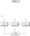
- FIG. 2 is a block diagram of a radar apparatus 100 according to an embodiment of the present disclosure.
- the radar apparatus 100 includes an antenna system 110 or an antenna member including a plurality of transmission antennas and a plurality of receiving antennas, a transceiver 120 transmitting transmission signals and receiving reception signals through the antenna system 110, and a processor 130 for processing the reception signal and calculating horizontal and/or vertical position information of the object.
- the radar apparatus is also called a radar sensor.
- the antenna system 110 may include a transmission antenna set including at least one first transmission antenna and a second transmission antenna spaced apart from the first transmission antenna by a first vertical distance B in a first direction perpendicular to a ground and a receiving antenna set including at least one receiving antenna disposed at the same vertical position as the first transmission antenna.
- the transmission antenna set may include three transmission antennas extending in a first direction perpendicular to the ground or in a vertical direction
- the receiving antenna set may include four receiving antennas extending in the first direction and disposed apart from the transmission antenna set by predetermined distance in a second direction perpendicular to the first direction.
- the radar apparatus has three transmission channels (transmission antennas) and four receiving channels (receiving antennas).
- the transmission antenna set may include a first transmission antenna including a first-1 transmission antenna TX0 and a first-2 transmission antenna TX1 having the same vertical position as the receiving antennas, a second transmission antenna TX2 spaced apart by a first vertical distance B from the first transmission antenna.
- the specific configuration of the antenna unit 110 will be described in more detail with reference to FIG. 3 below.
- the transceiver 120 includes: a transmitter that switches to one of the transmission antennas included in the antenna system 110 having a structure to be described with reference to FIG. 2 etc. and transmits a transmission signal through the switched transmission antenna or through a multi-transmitting channel assigned to the transmission antennas; and a receiver that switches to one of the receiving antennas and receives a reception signal that is a reflection signal of the transmission signal reflected from a target through the switched receiving antenna or through a multi-receiving channel assigned to the receiving antennas.
- the transceiver 120 may be controlled to transmit a code-divided transmission signal from the first-1 transmission antenna TX0 and the second transmission antenna TX2 in the first detection mode for a medium / long range detection, and may receive reflection signals at all of the receiving antennas.
- the transceiver may be controlled to transmit a transmission signal from the first-2 transmission antenna TX1 in the second detection mode for short distance detection, and may receive reflection signals at all of the receiving antennas.
- the processor 130 in the present embodiment may processes the transmission signal and the reception signal to calculate the position information of the object. More specifically, the processor 130 may calculate the position information of the object including the vertical information such as the elevation angle of the object and the mid/long range horizontal information such as the azimuth angle of the object exist in the mid/long distance by using the code-divided transmission signal transmitted from the first-1 transmission antenna TX0 and the second transmission antenna TX2 and the reception signal received at all of the receiving antennas
- the processor 130 may calculate the short range horizontal information such as the azimuth angle of the object exist in the short distance by using the transmission signal transmitted from the first-2 transmission antenna TX1 and the reception signal received at all of the receiving antennas
- the processor 130 may synthesize the signals received from the second receiving antenna RX1 and the third receiving antenna RX2 and may process it as one channel signal.
- the transmitter included in the transceiver 120 includes an oscillator that generates a transmission signal for one transmitting channel assigned to a switched transmission antenna or a multi-channel assigned to a plurality of transmission antennas.
- the oscillator for example, may include a voltage-controlled oscillator (VCO) and an oscillator.
- VCO voltage-controlled oscillator
- the receiver included in the transceiver 120 includes: a low-noise amplifier (LNA) that low-noise amplifies the reception signal received through one receiving channel assigned to a switched receiving antenna or through a multi-receiving channel assigned to a plurality of transmission antenna; a mixer that mixes the low-noise amplified reception signal; an amplifier that amplifies the mixed receiving signals; and an analog-to-digital converter (ADC) that generates reception data by digital-converting the amplified reception signal.
- LNA low-noise amplifier
- ADC analog-to-digital converter
- the radar apparatus 100 includes a processor 130 that controls a transmission signal and performs signal processing using reception data.
- the processor 130 allows for reducing costs and hardware size too by efficiently distributing signal processing, which requires a large amount of calculation, to a first processor and a second processor.
- the first processor included in the processor 130 is a pre-processor for the second processor and can obtain transmission data and reception data, control generation of a transmission signal by the oscillator based on the obtained transmission data, synchronize the transmission data and reception data, and changes frequencies of the transmission data and reception data.
- the second processor is a post-processor that actually performs processing using the processing result of the first processor and can perform CFAR (Constant False Alarm Rate) calculation, tracking, and target selection on the basis of the reception data with frequency changed by the first processor, and perform extract angular information, speed information, and distance information on a target.
- CFAR Constant False Alarm Rate
- the first processor can buffer the obtained transmission data and reception data into a sample size that can be processed for one cycle and change the frequency.
- the frequency change by the first processor may use Fourier transform such as FFT (Fast Fourier Transform).
- the second processor may perform second Fourier transform on the signals that has undergone first Fourier transform (FFT) by the first processor and the second Fourier transform, for example, may be Discrete Fourier Transform (hereafter, referred to as 'DFT'). Further, it may be chirp-DFT of DFT.
- FFT first Fourier transform
- 'DFT' Discrete Fourier Transform
- the second processor obtains frequency values corresponding to a second Fourier transform length (K) through the second Fourier transform, calculates a bit frequency having the largest power for each chirp period on the basis of the obtained frequency values, and obtain speed information and distance information of an object on the basis of the calculated bit frequency, whereby it can detect an object.
- K second Fourier transform length
- the radar apparatus may include the antenna systems shown in FIGS. 3 , and the transceiver 120 and the processor 130 may perform a predetermined signal transmitting/receiving manner and information calculation manner in order to acquire the vertical information and horizontal information of the object in both the mid/long range detection mode and the short range detection mode. These manners will be described in more detail below with reference to FIGs. 4 ⁇ 6 .
- the antenna system 110 included in the radar apparatus 100 may include a plurality of transmission antennas and a plurality of receiving antennas, and each of the transmission antennas and the receiving antennas may be array antennas of which a plurality of transmitting/receiving elements is connected in series by transmission wires, but they are not limited thereto.
- the antennas used in this embodiment are elongated in predetermined directions and the directions mean the directions in which the antennas are elongated with respect to a transmission port connected to a processor 130.
- FIG. 3 shows a first embodiment of arrangement of a plurality of transmission antennas and a plurality of receiving antennas included in an antenna system included in the radar apparatus according to an embodiment of the present disclosure.
- the up-direction of the vertical directions is defined as a first direction and the down-direction of the vertical directions is defined as a second direction herein.
- the receiving antenna set may include a total of four receiving antennas, and the first receiving antenna RX0, the second receiving antenna RX1, the third receiving antenna RX2, and the fourth receiving antenna RX3 are sequentially arranged spaced apart in the second direction perpendicular to the first direction.
- each of the first receiving antennas RX0 and the fourth receiving antennas RX3 may be disposed apart from a midpoint between the second receiving antenna RX1 and the third receiving antenna RX2 by a first horizontal distance A.
- Each of the first receiving antenna RX0 and the fourth receiving antenna RX3 may be configured as two array antennas and the second receiving antenna RX1, and each of the third receiving antenna RX2 may be configured as a single array antenna.
- the processor may synthesize the signals received from the second receiving antenna RX1 and the third receiving antenna RX2 to process as one channel signal.
- each receiving antenna may comprise a larger number of array antennas than one or two array antennas.
- the transmission antenna set may include a total of three transmission antennas.
- the first transmission antenna may include the first-1 transmission antenna TX0 including 4 or 6 array antennas, and the first-2 transmission antenna TX1 including two array antennas, and the second transmission antenna may include the second transmission antenna TX2 including 4 or 6 array antennas.
- the first-1 transmission antenna TX0 and the second transmission antenna TX2 may be disposed apart from each other by a second horizontal distance 2A corresponding to twice the first horizontal distance in the second direction.
- the second transmission antenna TX2 may be disposed apart from the first-1 transmission antenna TX0 and the first-2 transmission antenna TX1 by a first vertical distance B in the first direction.
- first-1 transmission antennas TX0 and second transmission antennas TX2 may be configured to include 4 or 6 array antennas which are connected to the same feed line to and simultaneously transmit a transmission signal.
- first-1 transmission antennas TX0 and second transmission antennas TX2 may be configured to include one or more array antennas depending on the required detection resolution.
- the transmission beam becomes sharp and the linearity of the transmission beam becomes higher. Therefore, it is possible to further improve the straightness of the transmission signal and the detecting distance by setting the number of array antennas of the first-1 transmission antenna TX0 and the second transmission antenna TX2 used in the long range detection mode to four or six.
- the first-2 transmission antenna TX1 is not necessarily composed of two array antennas, and may be composed of one or more array antennas.
- the each of the array antennas constituting the transmission antenna and the receiving antenna may include a plurality of elements or patches connected through a transmission line and a plurality of elements or patches may be extended to up-direction of the first direction from a start point that is a feeding port 320 connected to a chip 310 including a signal processor.
- the transmission antennas and the receiving antennas constituting the antenna apparatus may have a predetermined arrangement interval and will be described in detail below.
- the center point P between the second receiving antenna RX1 and the third receiving antenna RX2 is located apart from the center point of the two array antennas constituting the first receiving antenna RX0 by the first horizontal distance A in the horizontal direction (i.e. the second direction).
- the center point of the two array antennas constituting the fourth receiving antenna RX3 is spaced apart from the center point P between the second receiving antenna RX1 and the third receiving antenna RX2 by a first horizontal distance A.
- the second receiving antenna RX1 and the third receiving antenna RX2 may be arranged to be spaced apart from each other by a half (0.5 ⁇ ) of the wavelength of the transmission signal in the horizontal direction.
- an interval between the two array antennas constituting each of the first receiving antenna RX0 and the fourth receiving antenna RX3 may also be a half (0.5 ⁇ ) of the wavelength of the transmission signal.
- the interval between the two, four or six array antennas constituting each of the three transmission antennas may also be arranged to be spaced by a half (0.5 ⁇ ) of the wavelength of the transmission signal.
- the signals received from the second receiving antenna RX1 and the third receiving antenna RX2 are synthesized to be used as one channel signal, and the horizontal distance between the second receiving antenna RX1 and the third receiving antenna RX2 is set to a half (0.5 ⁇ ) of the wavelength of the transmission signal, so that the angle ambiguity due to the grating lobe may be eliminated.
- the grating lobe may occur because the interval between the receiving antennas is equal to or greater than a half (0.5 ⁇ ) of the wavelength of the transmission signal.
- the second receiving antenna RX1 and the third receiving antenna RX2 may be disposed so as the horizontal distance between the second receiving antenna RX1 and the third receiving antenna RX2 is 0.5 ⁇ and the angular information extracted from the two channels is compared and compensated, so that the angle uncertainty due to the grating lobe may be minimized.
- the vertical information of the object such as an elevation angle may be accurately measured by arranging at least two of the transmission antennas among the plurality of the transmission antennas constituting the transmission antenna being apart from each other by a predetermined vertical distance B in the vertical direction perpendicular to the ground.
- the vertical distance B may be determined in consideration of the frequency of the transmission signal and the measurement accuracy of vertical information of the object.
- the horizontal distance 2A between two transmission antennas may be a same distance as the horizontal distance 2A between the two receiving antennas disposed at the outermost of the four receiving antennas constituting the receiving antenna set, that is, the first receiving antenna RX0 and the fourth receiving antenna RX3.
- the entire aperture of the entire receiving antenna including the virtual receiving antenna formed in the receiving antenna set by the code division transmission and the real receiving antenna as the actual receiving antenna may be expanded, thereby the measurement resolution of the horizontal information in the mid / long range detection mode may be improved.
- the horizontal distance 2A between the first-1 transmission antenna TX0 and the second transmission antenna TX2 for simultaneously transmitting a transmission signal by code division is set to a same distance as the horizontal distance 2A between the first receiving antenna RX0 and the fourth receiving antenna RX3, so that the transmission beam may be kept sharp and thereby the detection performance of the radar may be improved.
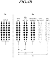
- FIG. 4 shows a case of detecting azimuth information using the radar apparatus according to the present disclosure, particularly, in which a timing diagram of signals in a mid/long-range detection mode ( FIG. 4A ) and an equivalent state diagram of transmitting and receiving antennas in this case ( FIG. 4B ) are provided.
- the transmission signal may be simultaneously transmitted by the first-1 transmission antenna TX0 and the second transmission antenna TX2 in the transmission mode in order to measure the horizontal information of the object at the medium or long distance by using the radar according to the present invention.
- the signals received from all the receiving antennas included in the receiving antenna set i.e., the receiving antennas RX0 through RX3 may be used to acquiring the horizontal information of the object at the medium or long distance.
- the signals received from the second receiving antenna RX1 and the third receiving antenna RX2 may be synthesized and used as one channel signal.
- each of a total of three transmission antennas TX0, TX1, and TX2 included in the transmission antenna set may be represented by the respective transmission channel, and each of a total of four receiving antennas RX1, RX2, RX3 and RX4 may be expressed as the respective receiving channel.
- the radar apparatus may utilize two transmission channels and three receiving channels for acquiring the horizontal information in the long range detection mode.
- the first-1 transmission antenna TX0 and the second transmission antenna TX2 of the two transmission channels may simultaneously transmitting the code-divided transmission signals in the transmission mode, and the receiving signal received from the three receiving channels (i.e., three channels of RX0, RX1 + RX2 and RX3) may be used in the reception mode.
- FIG. 4A is a timing diagram of the signal transmission and reception in the mid/long range detection mode.
- the first-1 transmission antenna TX0 and the second transmission antenna TX2 may be turned ON for a predetermined period of time in one predetermined detection period (0 ⁇ T) and may transmit one transmission signal having the first code A and the other transmission signal having the second code B at the same time.
- each of the four receiving antennas RX0 to RX3 may receive the reflection signal during the same detection period (0 ⁇ T).
- the processor 130 may analyze the receiving signals received from four receiving antennas and three channels (RX1 and RX2 are combined and used as one channel) and may obtain the horizontal information (width, etc.) of the object in the middle or long distance.
- Fig. 4B is an equivalent state diagram of transmission and receiving antennas in the mid/long range detection mode.
- the equivalent state diagram of FIG. 4B may illustrate the arrangement state of the receiving antennas when two transmission antennas transmitting the code-divided transmission signals are set to one transmission channel, and thereby the degree of aperture of the radar device may be confirmed.
- the position of the first-1 transmission antenna TX0 may be assumed as a reference position in FIG. 4B since the horizontal information of the object may be not affected by the vertical separation of the first transmission antenna and the second transmission antenna.
- the receiving antenna receiving the reflection signal reflected from the object may have the same effect as that the first code division receiving signal and the second code division receiving signal which have the same shape are shifted spatially in the horizontal direction by 2A.
- a receiving antenna which is virtually present due to the horizontal separation of transmission antennas may be expressed as "a virtual receiving antenna" in a concept distinguishable from actual receiving antennas.
- the first receiving antenna RX0, the second receiving antenna RX1, the third receiving antenna RX2 and the fourth receiving antenna RX3 may be real receiving antennas.
- FIG. 4 is for the case of obtaining horizontal direction information so that the vertical separation of the transmission and receiving antennas may not be considered. Therefore, for the sake of convenience, the vertical direction (first direction) separation is not shown in FIG. 4 .
- the second receiving antenna RX1 and the third receiving antenna RX2 may be synthesized as one signal in the receiving mode, they may be represented by one channel.
- three real receiving antennas including a first real receiving antenna RRXO, a second real receiving antenna RRX1 and a third real receiving antenna RRX2 may be formed in the receiving part.
- the second real receiving antennas antenna RRX2 arranged in the middle corresponds to a composite antenna of the second receiving antenna RX1 and the third receiving antenna RX2.
- the first-1 transmission antenna TX0 for transmitting the transmission signal with the first code is used as a reference and the second transmission antenna TX2 for simultaneously transmitting the transmission signal with the second code is spaced by 2A in the horizontal direction, thereby the receiving antenna that receives the signal transmitted from the second transmission antenna TX2 may have the same effect as that the position thereof may be shifted by 2A in the horizontal direction than the actual position.
- the receiving antenna formed at the shifted position may be expressed as a virtual receiving antenna VRX.
- the real receiving antennas that receive the transmission signals of the first-1 transmission antenna TX0 may be represented as RX0, RX1, RX2 and RX3, and virtual receiving antennas that receive the transmission signals of the second transmission antenna TX1 may be represented as RX0', RX1', RX2' and RX3' in order to distinguish them from the real receiving antennas.
- the real receiving antennas may be indicated by a solid line and the virtual receiving antennas may be indicated by a dotted line in FIG. 4B .
- three virtual receiving antennas including the first virtual receiving antenna VRXO, the second virtual receiving antenna VRX1 and the third virtual receiving antenna VRX2 having the same arrangement as the real receiving antennas may be formed at a position separated by 2A from the real receiving antenna.
- the first virtual receiving antenna VRX0 may correspond to the virtual receiving antenna RX0' of the first receiving antenna RX0
- the third virtual receiving antenna VRX2 may correspond to the virtual receiving antenna RX3' of the fourth receiving antenna RX3
- the second virtual receiving antenna VRX1 therebetween may correspond to the virtual receiving antenna RX1' + RX2' of the second and third receiving antenna which are synthesized into one signal.
- three real receiving antennas RRXO, RRX1, and RRX2 and three channels of virtual receiving antennas VRXO, VRX1 and VRX2 may be formed in the receiving part.
- the real receiving antennas and the corresponding virtual receiving antennas are also spaced apart by a horizontal distance 2A.
- the position of the first virtual receiving antenna VRX0 may be exactly overlapped with the position of the third real receiving antenna RRX2 (i.e., the fourth receiving antenna RX3).
- a first real receiving antenna RX0 or RRXO, a second real receiving antenna RRX1 or a composite antenna of RX1 + RX2, a third real receiving antenna RRX2 or RX3 and a first virtual receiving antenna VRX0 or RX0' overlapped therewith, a second virtual receiving antenna VRX1 or a composite antenna of RX1'+RX2', and a third virtual receiving antenna VRX2 or RX3' may be sequentially arranged with a horizontal distance A from the left side in the receiving part.
- the entire aperture of the receiving antenna set i.e., the horizontal distance between the first real receiving antenna RRX0 disposed at one end and the third virtual receiving antenna VRX2 disposed at the other end may be 4A.
- the entire aperture of the receiving antenna may be extended to 4A, thereby improving the resolution of the horizontal direction information in the long range detection mode.
- a radar apparatus performs an object detection function that detects the distance to an object and the speed and azimuth of the object using reception signals received through a plurality of receiving antennas, in which in order to increase precision of detection of an object (that is, increase resolution), it is preferable that the radar apparatus has an antenna system with an "expanded aperture structure" by increasing the gaps between the receiving antennas.
- the distance from an end to the other end of a receiving antenna is the aperture and it is a very important factor of the performance of a radar apparatus to provide an expanded aperture performance by increasing the aperture of the receiving antenna.
- the position where a grating lobe is generated at the receiving end is moved closer to the center position where the main beam is positioned.
- an "expanded aperture structure” or a “virtual antenna system” is provided for the radar apparatus according to an embodiment of the present disclosure in order to move the position where a grating lobe is generated away from the center position where the main beam is positioned, that is, to suppress grating lobe.
- the radar apparatus 100 may further include a virtual RX antenna creator 140 for creating a plurality of virtual RX antennas.
- the virtual RX antenna creator 140 can perform signal processing for generating signals having a predetermined phase difference that depends on the gap between receiving antennas on the basis of a signals received by actual receiving antennas.
- the virtual RX antenna creator 140 performs signal process for generating a virtual signal (a signal having a phase difference from the actually received signal) as if a signal has been received through a virtual RX antenna that virtually exists at a position where there is no actual receiving antenna.
- the "creating a virtual RX antenna” herein may have the same meaning as "a reception signal that has not been actually received is generated".
- the arrangement structure (gap, number etc.) of virtual RX antennas may have the same meaning as the structure (gap, number etc.) of reception signals that are not actually received.
- the virtual RX antenna creator 140 an antenna system in which not only a plurality of receiving antennas actually exist, but a plurality of virtual RX antennas virtually exist at the receiving end can be provided.
- the antenna system including a plurality of virtual RX antennas virtually existing at the receiving end may be expressed as an "antenna system having a virtual aperture structure”.
- the transceiver 120 of the radar apparatus in the mid/long-range detection mode, may simultaneously transmit the code-divided signals through the first-1 transmission antenna TX0 and the second transmission antenna TX2 which are spaced apart from each other by the horizontal distance 2A and the vertical distance B, and may receive and analyze the signals received from the first real receiving antenna, the second real receiving antenna, the third real receiving antenna (or the first virtual receiving antenna), the second virtual receiving antenna and the third virtual receiving antenna which are sequentially spaced apart by a horizontal distance A, thereby it is possible to measure the horizontal information (azimuth angle, etc.) of the target at a medium or longer distance with high resolution.
- the radar apparatus may provide the extended aperture performance and may be capable of precisely measuring the horizontal information of the medium or long distance object by using the antenna arrangement structure or the antenna system as shown in FIG. 3 and the signal transmission and receiving structure as shown in FIG. 4 .
- FIG. 5 shows a case of detecting azimuth information using the radar apparatus according to the present disclosure, in which a timing diagram of signals in a short range detection mode ( FIG. 5A ) and an equivalent state diagram of transmitting and receiving antennas in this case ( FIG. 5B ) are provided.
- the transceiver 120 of the radar apparatus may transmit transmission signals through the first-2 transmission antenna TX1 arranged in the center position among the three transmission antennas, and may receive a reflection signal through all of the four receiving antennas RX0 to RX3.
- the second receiving antenna RX1 and the third receiving antenna RX2 also may be combined and used as one receiving channel, so that a total of one transmission channel and three receiving channels may be used in the short range detection mode.
- the first-2 transmission antenna TX1 may be turned ON for a predetermined period of time in one detection period (0 ⁇ T) and may transmit the transmission signal, and all of the four receiving antennas RX0 to RX3 may receive the reflection signals. (all of the four receiving antennas are turned ON)
- the processor 130 may compare and analyze the transmission signal transmitted through the first-2 transmission antenna and the reception signal received through the four receiving antennas or three receiving channels, and may acquire the position information of the object in short distance.
- the aperture of the transmission part may be set to 0.5 ⁇ which is the interval between two array antennas constituting the first-2 transmission antenna TX1.
- the distance between the second receiving antenna RX1 and the third receiving antenna RX2 may be set to 0.5 ⁇ so that the angle information extracted from the signals received by the two receiving antennas are compared with each other, and the angle ambiguity due to the grating lobe may be eliminated.
- the radar apparatus 100 or the transceiver 120 and the processor 130 and the virtual RX antenna creator 140 included in the radar apparatus may be may be implemented as a radar control device that performs an object identification function by a radar or as a module of an ECU
- the radar control device or the ECU may include a processor, a storage such as and a memory and a computer program capable of performing a specific function.
- the transceiver 120, the processor 130, and the virtual RX antenna creator 140 may be implemented as software modules capable of performing their respective functions.
- the radar apparatus 100 may be implemented as a computer system connected to the antenna system.
- the computer system may include one or more element of a processors, a memory, a storage, a user interface input and a user interface output, which are capable of communicating with one another via a communication bus.
- the computer system may also include a network interface for connecting to a network.
- the processor may be a CPU or a semiconductor device that executes processing instructions stored in memory and/or in the storage.
- Memory and storage may include various types of volatile/non-volatile storage media.
- the memory may include ROM and RAM.
- a software or a program for performing the functions of the transceiver 120, the processor 130, and the virtual RX antenna creator 140 may be stored or installed in the memory or the storage unit, and may be executed by the processor.
- the computer system for performing the controlling of the radar apparatus 100 may execute software stored in a memory so as to transmit the transmission signal through the transmission antenna set and acquire the object information based on the reception signal received through the receiving antenna set as above.
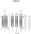
- FIG. 6 is an equivalent state diagram of a transmission antenna and receiving antenna for detecting vertical information or the elevation information by using an antenna according to an embodiment of the present disclosure.
- a code-divided signals may be simultaneously transmitted from the first-1 transmission antenna TX0 and a second transmission antenna TX2 which are two transmission antennas spaced apart from each other by a vertical distance B in the vertical direction, and the reflection signals may be received from the plurality of receiving antennas, thereby it is possible to acquire the vertical information of the target such as the elevation angle.
- the transceiver 120 may be operable to turn ON the first-1 transmission antenna TX0 and the second transmission antenna TX2 for a predetermined period of time in one detection period (0 ⁇ T) and may transmit one transmission signal having the first code A and the other transmission signal having the second code B at the same time.
- each of the four receiving antennas RX0 to RX3 may receive the reflection signal during the same detection period (0 ⁇ T).
- the processor 130 may analyze the receiving signals received from four receiving antennas and three channels (RX1 and RX2 are combined and used as one channel) and may obtain the vertical information (height, etc.) or he elevation information of the object.
- FIG. 6 is an equivalent state diagram of a transmission and receiving antenna for detecting vertical information.
- the position of a first-1 transmission antenna TX0 for transmitting a transmission signal with the first code may be used a reference position
- the horizontal position of the second transmission antenna TX2 for transmitting the transmission signal with the second code may be identically expressed as the horizontal position of the first-1 transmission antenna in order to illustrate only the vertical positional relationship.
- the second receiving antenna RX1 and the third receiving antenna RX2 may be combined and used as one receiving channel. Therefore, as shown in the right part of FIG. 6 , three real receiving antennas RRX0 ⁇ RRX2 and the three virtual receiving antennas VRX0 ⁇ VRX2 may be formed, and the third real receiving antenna RRX2 and the first virtual receiving antenna VRX0 may be exactly overlapped with each other in the horizontal direction but may be spaced apart from each other by the vertical distance B in the vertical direction.
- a first real receiving antenna RRX0 as the first receiving antenna RX0
- a second real receiving antenna RRX1 as the combined antenna of second receiving antenna RX1 and a third receiving antenna RX2
- a third real receiving antenna RRX2 as a third receiving antenna RX2 and a first virtual receiving antenna VRX0 or RX0' horizontally overlapped therewith
- a second virtual receiving antenna VRX1 or a combined antenna of RX1'+ RX2'
- a third virtual receiving antenna VRX2 or RX3' are sequentially arranged in the receiving part of the antenna system.
- the third real receiving antenna RRX2 and the first virtual receiving antenna VRX0 or RX0' horizontally overlapped therewith may be spaced apart from each other by the vertical distance B in the vertical direction.
- a phase difference or amplitude difference may occur between the receiving signals received by the respective reception channels or between the transmission signals and the corresponding receiving signals due to the vertical distance separation.
- the vertical information such as the height of the object or the elevation angle may be acquired by comparing the phase difference or amplitude difference of the signal for each receiving channel.
- the propagation paths (propagation distance) of signals received by two receiving channels (for example, a third real receiving antenna and a first virtual receiving antenna) spaced by a vertical distance B in the vertical direction may be different from each other, thereby the phase or the amplitude of the receiving signal at each receiving channel may also be different from each other.
- the processor 130 of the radar apparatus may analyze the difference of the phase or the amplitude of the receiving signal at each receiving channel and can acquire the vertical information such as the height of the object.
- the same transmission and reception method is used for obtaining horizontal information in the long range detection mode.
- phase compensation may be first performed based on the vertical separation of the signals received in each receiving channel of the equivalent antenna state as shown in FIG. 6 , and then the processing for obtaining horizontal information may be performed.
- the vertical information of the object may be acquired first as shown in FIG. 6 based on the reception signal received by using the manner as shown FIG. 4 , the compensation of the phase difference of the received signal due to the vertical spacing may be performed, and then the horizontal information of the long-distance object as described in Fig. 4B may be obtained.
- the vertical information and the horizontal information of the object may be obtained with high precision in both the long range detection mode and the short range detection mode by using the manner described above with reference to FIGS. 4 ⁇ 6 .
- the radar apparatus of the present embodiment since the vertical information and horizontal information of the long range and the short range can be precisely measured without any physical change of the radar device or an additional device, the utility as the radar sensor for the vehicle may be maximized.
- the radar apparatus may utilize a MIMO antenna system in order to achieve a high detection accuracy or resolution in vertical and horizontal directions.
- each transmission antenna may transmit a signal having an independent waveform different from each other in a MIMO system. That is, each transmission antenna transmits a signal of an independent waveform differentiating from that for the other transmission antennas, and each receiving antenna may determine the transmission antenna transmitting the transmission signal correspondent with the received signal reflected from the target due to the different waveforms of these signals.
- the radar apparatus may be configured to include a radar housing for accommodating a substrate and a circuit including the transmission antenna and the receiving antenna, and a radome forming the exterior of the radar housing.
- the radome may be made of a material capable of reducing the attenuation of the radar signal transmitted and received, and the radome may be constituted as a part of an outer surface of the vehicle component such as the front bumper, the rear bumper, the grill of the vehicle and the side body of the vehicle.
- the radome of the radar apparatus may be disposed inside a vehicle grill, a bumper, a vehicle body, and may be disposed as a part of the outer surface of a part of the vehicle body, as a result, it is possible to provide a convenience in mounting the radar sensor to the vehicle while improving the appearance of the vehicle.
- a radar apparatus or a radar system may include at least one of a front detection radar sensor mounted on the front of the vehicle, a rear detection radar sensor mounted on the rear of the vehicle, and a side detection radar sensor mounted on respective side of the vehicle.
- the radar apparatus or radar system may include an electronic control unit (ECU) or a processor for analyzing the transmission and reception signals and processing the data and thereby for acquiring information of the target.
- ECU electronice control unit
- a communication link including an appropriate vehicle network bus such as a CAN may be utilized for the data transmission or signal communication between the radar sensor device and the ECU.
- the horizontal information may be used with the same meaning as the azimuth information or azimuth angle
- the vertical information may be used with the same meaning as the elevation information or the elevation angle
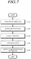
- FIG. 7 is a flowchart illustrating a signal processing method provided by the radar apparatus according to an embodiment of the present disclosure.
- FIG. 7 is a flowchart showing signal processing after signals are received by the signal transmission/reception method described above with reference to FIGS. 4 to 6 .
- the reception data obtained in step S710 may be data-buffered in a unit sample size being processable in one cycle (S720), and then frequency conversion (S730) is performed
- the method performs CFAR (Constant False Alarm Rate) calculation on the basis of the frequency-changed reception data (S740) and extract elevation/azimuth information, speed information, and distance information of a target (S750).
- the frequency change in step S730 may use Fourier transform such as FFT (Fast Fourier Transform).
- FIG. 8 shows differences in a signal waveform and a frequency band in a mid/long range detection mode and a short range detection mode in a radar apparatus according to an embodiment of the present disclosure.
- using the radar apparatus according to this embodiment makes it possible to precisely measure azimuth information of an object in both a mid/long-range detection mode and a short-range detection mode.
- the radar apparatus may improve sensing performance by using frequency bands and signal waveforms that are different in the mid/long-range detection mode and the short-range detection mode, which is described in detail hereafter.
- radar apparatus may have a wide frequency band for transmission signals, large output, and resolving power or signal sensing performance that is improved as the number of waveforms output in one sensing period is increased.
- the available frequency bands of automotive radars are limited to avoid interference with other vehicles or other electronic waves in a mid/long-range detection mode. That is, the automotive radars can use wide frequency band in a short-range detection mode because there is a low possibility of interference with other radar apparatuses, but available frequency bands are limited in many cases in a mid/long-range detection mode to avoid interference.
- a first transmission signal in the mid/long-range detection mode shown in FIG. 4 uses a first frequency band and have a first number signal waveforms (Chirp) that are relatively fewer in one sensing period T, and as second transmission signal in the short-range detection mode uses a second frequency band higher than the first frequency band and have a second number of signal waveforms larger than the first number in one sensing period.
- output of transmission signals can be larger in the mid/long-range detection mode than the short-range detection mode.
- so-called slow chirp transmission signals that are generated in the first frequency band of about 76 ⁇ 77GHz and have a large waveform width are used in the mid/long-range detection mode.
- fast chirp transmission signals that are generated in the second frequency band of about 76 ⁇ 81GHz higher than the first frequency band and have a small width of waveform are used in the short-range detection mode.
- the first number N1 of waveforms (Chirp) included in one sensing period T or cycle in the mid/long-range detection mode is smaller than the second number N1 of waveforms included in the one sensing period in the short-range detection mode.
- the first frequency band and the second frequency band may overlap each other or may be completely different frequency bands.
- the fast chirp type that outputs a plurality of waveforms for one sensing cycle has high sensing performance instead of an increase in data and particularly it can secure desired resolution from low output.
- the radar apparatus of this embodiment includes the antenna systems shown in FIGS. 3 , and in order to obtain azimuth/elevation information of an object, uses the signal transmission/reception methods shown in FIGS. 4 to 6 and makes frequency bands and signal waveforms of transmission signals different in a short-range detection mode and a mid/long-range detection mode, thereby being able to avoid interference with other radar apparatuses and measure azimuth/elevation information of an object with high resolution at both a mid/long distance and a short distance.
- two transmission antennas disposed on both sides of the transmission antenna set may be arranged apart from each other by a predetermined vertical distance in a first direction perpendicular to the ground, and the four receiving antennas may be disposed apart from each other by a predetermined horizontal distance, so that the vertical information and the horizontal information of the object can be easily obtained in the long range detection mode and the short range detection mode.
- the transmission antennas for transmitting the transmission signals is differently selected in the long range detection mode and the short range detection mode, thereby the vertical information and the horizontal information of the object can be obtained in the long range detection mode and the short range detection mode.
- the shapes of the frequency band and the signal waveform of the transmission signal may be different from each other in the long range detection mode and the short range detection mode, so that the measurement resolution of the horizontal / vertical information of the object may be improved in both long range detection mode and the short range detection mode, and an interference with other radar devices may be prevented.
- the frequency bands and waveforms of transmission signals are made different in the short-range detection mode and the mid/long-range detection mode, it is possible to avoid interference with other radar apparatuses and improve resolution in measuring azimuth/elevation information of an object at both of a mid/long distance and a short distance.
Landscapes
- Engineering & Computer Science (AREA)
- Radar, Positioning & Navigation (AREA)
- Remote Sensing (AREA)
- Physics & Mathematics (AREA)
- Computer Networks & Wireless Communication (AREA)
- General Physics & Mathematics (AREA)
- Electromagnetism (AREA)
- Computer Security & Cryptography (AREA)
- Radar Systems Or Details Thereof (AREA)
Applications Claiming Priority (1)
| Application Number | Priority Date | Filing Date | Title |
|---|---|---|---|
| KR1020180040831A KR102167084B1 (ko) | 2018-04-09 | 2018-04-09 | 레이더 장치 및 그를 위한 안테나 장치 |
Publications (1)
| Publication Number | Publication Date |
|---|---|
| EP3553558A1 true EP3553558A1 (de) | 2019-10-16 |
Family
ID=66102983
Family Applications (1)
| Application Number | Title | Priority Date | Filing Date |
|---|---|---|---|
| EP19168195.6A Pending EP3553558A1 (de) | 2018-04-09 | 2019-04-09 | Radarvorrichtung und antennenvorrichtung dafür |
Country Status (4)
| Country | Link |
|---|---|
| US (1) | US11874363B2 (de) |
| EP (1) | EP3553558A1 (de) |
| KR (1) | KR102167084B1 (de) |
| CN (1) | CN110361739A (de) |
Families Citing this family (30)
| Publication number | Priority date | Publication date | Assignee | Title |
|---|---|---|---|---|
| US20200241122A1 (en) * | 2019-01-28 | 2020-07-30 | Metawave Corporation | Radar system with three-dimensional beam scanning |
| JP7150068B2 (ja) * | 2019-01-31 | 2022-10-07 | 三菱電機株式会社 | アンテナ装置及びレーダ装置 |
| JP7276447B2 (ja) * | 2019-06-25 | 2023-05-18 | 株式会社村田製作所 | 受信装置、並びに、それを備えるレーダ装置、車両および通信システム |
| US11754669B2 (en) * | 2019-09-30 | 2023-09-12 | Qualcomm Incorporated | Radar coordination for multi-radar coexistence |
| CN112698296B (zh) * | 2019-10-22 | 2024-08-30 | 广州极飞科技股份有限公司 | 一种雷达天线、雷达、无人机和设备 |
| CN112698299B (zh) * | 2019-10-22 | 2024-08-30 | 广州极飞科技股份有限公司 | 一种雷达天线、雷达、无人机和设备 |
| CN112368590A (zh) * | 2019-10-31 | 2021-02-12 | 深圳市大疆创新科技有限公司 | 微波天线结构、微波旋转雷达及可移动平台 |
| KR102279302B1 (ko) * | 2019-11-07 | 2021-07-20 | 현대모비스 주식회사 | 차량용 레이더 장치 및 그 제어 방법 |
| CN112154571B (zh) * | 2019-11-19 | 2023-05-12 | 深圳市大疆创新科技有限公司 | 阵列天线及其信号处理方法、毫米波雷达 |
| EP3862773A1 (de) * | 2020-02-04 | 2021-08-11 | Aptiv Technologies Limited | Radarvorrichtung |
| CN111555015B (zh) * | 2020-06-12 | 2025-08-22 | 中国气象局气象探测中心 | 一种双偏振相控阵天气雷达 |
| DE102020119934A1 (de) * | 2020-07-29 | 2022-02-03 | Valeo Schalter Und Sensoren Gmbh | Verfahren zum Betreiben eines Radarsystems, Radarsystem und Fahrzeug mit wenigstens einem Radarsystem |
| US11815589B2 (en) * | 2020-08-28 | 2023-11-14 | Nxp B.V. | Multiple-mode radar with resolution of spatial ambiguity |
| KR102363729B1 (ko) * | 2020-09-10 | 2022-02-15 | 재단법인대구경북과학기술원 | 레이더 탐지장치 및 그 동작 방법 |
| US11693107B2 (en) * | 2020-09-29 | 2023-07-04 | Steradian Semiconductors Private Limited | System, device and method for efficient MIMO radar |
| EP3978951B1 (de) * | 2020-10-03 | 2025-01-22 | HENSOLDT Sensors GmbH | Mimo-radarsystem für ein luftfahrzeug |
| WO2022107912A1 (ko) * | 2020-11-18 | 2022-05-27 | 주식회사 에이티코디 | 비대칭 광각 레이다 모듈 |
| KR102483340B1 (ko) * | 2020-11-27 | 2022-12-30 | 한화시스템 주식회사 | 모의 표적 신호 생성 장치 및 이를 이용한 레이더 시스템의 시험 방법 |
| CN114690170A (zh) * | 2020-12-30 | 2022-07-01 | 杭州海康威视数字技术股份有限公司 | 一种目标探测方法、装置及电子设备 |
| US11860297B2 (en) * | 2021-03-08 | 2024-01-02 | GM Global Technology Operations LLC | High resolution unambiguous radar |
| CN112986918B (zh) * | 2021-03-10 | 2025-08-01 | 浙江大华技术股份有限公司 | 一种雷达天线系统及一种信号处理方法 |
| CN115275647A (zh) * | 2021-04-30 | 2022-11-01 | 华为技术有限公司 | 一种天线、探测装置和终端 |
| KR102812952B1 (ko) * | 2021-07-05 | 2025-05-28 | 주식회사 에이치엘클레무브 | 차량용 레이더 장치 및 제어방법 |
| KR20230018914A (ko) * | 2021-07-30 | 2023-02-07 | 엘지이노텍 주식회사 | 감지 장치, 차량용 감지 시스템 및 이의 동작 방법 |
| KR102858815B1 (ko) * | 2021-11-19 | 2025-09-12 | 주식회사 에이치엘클레무브 | 레이더 제어 장치 및 방법 |
| KR102666994B1 (ko) * | 2021-12-13 | 2024-05-17 | 한국과학기술원 | 낮은 측엽 레벨을 가지는 배열 안테나 |
| EP4515630A4 (de) * | 2022-04-29 | 2026-04-22 | John Mezzalingua Ass Llc | Massive mimo-strahlformungsantenne mit verbesserter verstärkung |
| US12578426B2 (en) * | 2022-05-31 | 2026-03-17 | Infineon Technologies Ag | Channel offset correction for radar data |
| KR20240087982A (ko) * | 2022-12-13 | 2024-06-20 | 삼성전자주식회사 | 레이더 신호 처리 방법 및 장치 |
| CN117411497B (zh) * | 2023-12-13 | 2024-02-13 | 中山大学 | 一种全双工相控阵列及其射频去耦网络 |
Citations (8)
| Publication number | Priority date | Publication date | Assignee | Title |
|---|---|---|---|---|
| US20080024353A1 (en) * | 2003-12-19 | 2008-01-31 | Robert Bosch Gmbh | Radar Sensor and Method for Its Operation |
| US20140104097A1 (en) * | 2010-12-29 | 2014-04-17 | Thomas Binzer | radar sensor for motor vehicles |
| DE102013216951A1 (de) * | 2013-08-26 | 2015-02-26 | Robert Bosch Gmbh | Radarsensor für Kraftfahrzeuge |
| US20150204972A1 (en) * | 2014-01-21 | 2015-07-23 | Robert Bosch Gmbh | Method for angle estimation and radar sensor for motor vehicles |
| EP3156817A1 (de) * | 2015-10-12 | 2017-04-19 | Delphi Technologies, Inc. | Mimo-antenne mit höhenwinkeldetektion |
| US20170293028A1 (en) * | 2014-10-06 | 2017-10-12 | Astyx Gmbh | Imaging Radar Sensor with Horizontal Digital Beam Forming and Vertical Object Measurement by Phase Comparison in Mutually Offset Transmitters |
| US20170307744A1 (en) * | 2014-09-23 | 2017-10-26 | Robert Bosch Gmbh | Mimo radar device for the decoupled determination of an elevation angle and an azimuth angle of an object and method for operating a mimo radar device |
| EP3413077A1 (de) * | 2017-06-09 | 2018-12-12 | Veoneer Sweden AB | Verbesserte vertikale objekterkennung für ein kraftfahrzeug-radarsystem |
Family Cites Families (13)
| Publication number | Priority date | Publication date | Assignee | Title |
|---|---|---|---|---|
| CA2468492A1 (en) * | 2001-11-29 | 2003-06-05 | Interdigital Technology Corporation | Efficient multiple input multiple output system for multi-path fading channels |
| KR101137088B1 (ko) * | 2010-01-06 | 2012-04-19 | 주식회사 만도 | 통합 레이더 장치 및 통합 안테나 장치 |
| JP5853489B2 (ja) * | 2011-08-23 | 2016-02-09 | 日本電気株式会社 | 目標運動推測システム及び方法 |
| DE102011113015A1 (de) * | 2011-09-09 | 2013-03-14 | Astyx Gmbh | Abbildender Radarsensor mit synthetischer Vergrößerung der Antennenaperatur und zweidimensionaler Strahlschwenkung |
| DE102011113018A1 (de) | 2011-09-09 | 2013-03-14 | Astyx Gmbh | Abbildender Radarsensor mit schmaler Antennenkeule und weitem Winkel-Detektionsbereich |
| US9568600B2 (en) * | 2014-03-05 | 2017-02-14 | Delphi Technologies, Inc. | MIMO antenna with elevation detection |
| US9541639B2 (en) * | 2014-03-05 | 2017-01-10 | Delphi Technologies, Inc. | MIMO antenna with elevation detection |
| CN106546983B (zh) * | 2015-09-17 | 2021-11-12 | 松下电器产业株式会社 | 雷达装置 |
| DE102015222884A1 (de) * | 2015-11-19 | 2017-05-24 | Conti Temic Microelectronic Gmbh | Radarsystem mit verschachtelt seriellem Senden und parallelem Empfangen |
| DE102016203160A1 (de) * | 2016-02-29 | 2017-08-31 | Robert Bosch Gmbh | Radarsystem, umfassend eine Antennenanordnung zum Senden und Empfangen elektromagnetischer Strahlung |
| JP6853642B2 (ja) * | 2016-09-26 | 2021-03-31 | パナソニック株式会社 | レーダ装置 |
| KR102662232B1 (ko) * | 2016-11-28 | 2024-05-02 | 주식회사 에이치엘클레무브 | 다중입력 다중출력 안테나부를 포함하는 레이더 장치 |
| DE102016224900A1 (de) * | 2016-12-14 | 2018-06-14 | Robert Bosch Gmbh | MIMO-Radarsensor für Kraftfahrzeuge |
-
2018
- 2018-04-09 KR KR1020180040831A patent/KR102167084B1/ko active Active
-
2019
- 2019-04-09 US US16/379,109 patent/US11874363B2/en active Active
- 2019-04-09 EP EP19168195.6A patent/EP3553558A1/de active Pending
- 2019-04-09 CN CN201910279558.0A patent/CN110361739A/zh active Pending
Patent Citations (8)
| Publication number | Priority date | Publication date | Assignee | Title |
|---|---|---|---|---|
| US20080024353A1 (en) * | 2003-12-19 | 2008-01-31 | Robert Bosch Gmbh | Radar Sensor and Method for Its Operation |
| US20140104097A1 (en) * | 2010-12-29 | 2014-04-17 | Thomas Binzer | radar sensor for motor vehicles |
| DE102013216951A1 (de) * | 2013-08-26 | 2015-02-26 | Robert Bosch Gmbh | Radarsensor für Kraftfahrzeuge |
| US20150204972A1 (en) * | 2014-01-21 | 2015-07-23 | Robert Bosch Gmbh | Method for angle estimation and radar sensor for motor vehicles |
| US20170307744A1 (en) * | 2014-09-23 | 2017-10-26 | Robert Bosch Gmbh | Mimo radar device for the decoupled determination of an elevation angle and an azimuth angle of an object and method for operating a mimo radar device |
| US20170293028A1 (en) * | 2014-10-06 | 2017-10-12 | Astyx Gmbh | Imaging Radar Sensor with Horizontal Digital Beam Forming and Vertical Object Measurement by Phase Comparison in Mutually Offset Transmitters |
| EP3156817A1 (de) * | 2015-10-12 | 2017-04-19 | Delphi Technologies, Inc. | Mimo-antenne mit höhenwinkeldetektion |
| EP3413077A1 (de) * | 2017-06-09 | 2018-12-12 | Veoneer Sweden AB | Verbesserte vertikale objekterkennung für ein kraftfahrzeug-radarsystem |
Also Published As
| Publication number | Publication date |
|---|---|
| KR20190117900A (ko) | 2019-10-17 |
| CN110361739A (zh) | 2019-10-22 |
| US11874363B2 (en) | 2024-01-16 |
| KR102167084B1 (ko) | 2020-10-16 |
| US20190310358A1 (en) | 2019-10-10 |
Similar Documents
| Publication | Publication Date | Title |
|---|---|---|
| US11874363B2 (en) | Radar apparatus and antenna apparatus therefor | |
| US11796662B2 (en) | Radar apparatus and antenna apparatus therefor | |
| CN108120958B (zh) | 具有多输入多输出天线的雷达装置 | |
| CN108120957B (zh) | 雷达装置及其天线装置 | |
| KR102662238B1 (ko) | 레이더 장치 및 그를 위한 안테나 장치 | |
| US10629998B2 (en) | Radar apparatus and error correction method thereof | |
| KR102746695B1 (ko) | 차량용 레이더 센서장치 및 물체 감지방법과 그를 위한 안테나 장치 | |
| KR102814886B1 (ko) | 레이더 장치, 레이더 장치용 안테나 장치 및 레이더 장치의 제어 방법 | |
| KR102651145B1 (ko) | 레이더 장치 및 그를 위한 안테나 장치 | |
| CN113625280B (zh) | 车辆用雷达装置、雷达装置的控制方法及车辆用雷达系统 | |
| KR20210109855A (ko) | 차량용 레이더의 송신신호 위상 보정 장치 및 방법과, 그를 포함하는 차량용 레이더 장치 | |
| CN111180905A (zh) | 阵列天线布阵和汽车 | |
| KR102689273B1 (ko) | 레이더 장치 | |
| JP7306891B2 (ja) | レーダ装置およびレーダ装置の対象物検出方法 | |
| KR20220089824A (ko) | 이동기기 장애물감지용 스마트센서장치 | |
| US12360238B2 (en) | Vehicle radar apparatus and method of controlling the same | |
| KR102689268B1 (ko) | 차량용 레이더 장치 및 제어방법 |
Legal Events
| Date | Code | Title | Description |
|---|---|---|---|
| PUAI | Public reference made under article 153(3) epc to a published international application that has entered the european phase |
Free format text: ORIGINAL CODE: 0009012 |
|
| STAA | Information on the status of an ep patent application or granted ep patent |
Free format text: STATUS: REQUEST FOR EXAMINATION WAS MADE |
|
| 17P | Request for examination filed |
Effective date: 20190409 |
|
| AK | Designated contracting states |
Kind code of ref document: A1 Designated state(s): AL AT BE BG CH CY CZ DE DK EE ES FI FR GB GR HR HU IE IS IT LI LT LU LV MC MK MT NL NO PL PT RO RS SE SI SK SM TR |
|
| AX | Request for extension of the european patent |
Extension state: BA ME |
|
| RBV | Designated contracting states (corrected) |
Designated state(s): AL AT BE BG CH CY CZ DE DK EE ES FI FR GB GR HR HU IE IS IT LI LT LU LV MC MK MT NL NO PL PT RO RS SE SI SK SM TR |
|
| STAA | Information on the status of an ep patent application or granted ep patent |
Free format text: STATUS: EXAMINATION IS IN PROGRESS |
|
| 17Q | First examination report despatched |
Effective date: 20210921 |
|
| RAP1 | Party data changed (applicant data changed or rights of an application transferred) |
Owner name: MANDO MOBILITY SOLUTIONS CORPORATION |
|
| RAP1 | Party data changed (applicant data changed or rights of an application transferred) |
Owner name: HL KLEMOVE CORP. |