EP3553501A1 - Measuring device, measurement abnormality detecting method, and program - Google Patents
Measuring device, measurement abnormality detecting method, and program Download PDFInfo
- Publication number
- EP3553501A1 EP3553501A1 EP17877866.8A EP17877866A EP3553501A1 EP 3553501 A1 EP3553501 A1 EP 3553501A1 EP 17877866 A EP17877866 A EP 17877866A EP 3553501 A1 EP3553501 A1 EP 3553501A1
- Authority
- EP
- European Patent Office
- Prior art keywords
- measurement
- light
- irradiation area
- abnormality
- target region
- Prior art date
- Legal status (The legal status is an assumption and is not a legal conclusion. Google has not performed a legal analysis and makes no representation as to the accuracy of the status listed.)
- Granted
Links
- 238000005259 measurement Methods 0.000 title claims abstract description 327
- 230000005856 abnormality Effects 0.000 title claims abstract description 76
- 238000000034 method Methods 0.000 title claims description 27
- 238000006243 chemical reaction Methods 0.000 claims description 49
- 239000000126 substance Substances 0.000 claims description 26
- 238000005562 fading Methods 0.000 claims description 16
- 238000001514 detection method Methods 0.000 claims description 11
- 230000006870 function Effects 0.000 claims description 8
- 230000005764 inhibitory process Effects 0.000 claims description 5
- 238000005842 biochemical reaction Methods 0.000 claims 2
- 230000000052 comparative effect Effects 0.000 abstract 1
- 230000005855 radiation Effects 0.000 abstract 1
- 239000000427 antigen Substances 0.000 description 11
- 102000036639 antigens Human genes 0.000 description 11
- 108091007433 antigens Proteins 0.000 description 11
- 230000005284 excitation Effects 0.000 description 11
- 239000002184 metal Substances 0.000 description 10
- 239000010409 thin film Substances 0.000 description 10
- 230000007423 decrease Effects 0.000 description 6
- 239000000243 solution Substances 0.000 description 6
- 239000012491 analyte Substances 0.000 description 5
- 238000012937 correction Methods 0.000 description 4
- 230000003287 optical effect Effects 0.000 description 4
- 239000012086 standard solution Substances 0.000 description 3
- 208000005422 Foreign-Body reaction Diseases 0.000 description 2
- 230000004520 agglutination Effects 0.000 description 2
- 238000010586 diagram Methods 0.000 description 2
- 230000000694 effects Effects 0.000 description 2
- 230000005684 electric field Effects 0.000 description 2
- 239000007788 liquid Substances 0.000 description 2
- TVZRAEYQIKYCPH-UHFFFAOYSA-N 3-(trimethylsilyl)propane-1-sulfonic acid Chemical compound C[Si](C)(C)CCCS(O)(=O)=O TVZRAEYQIKYCPH-UHFFFAOYSA-N 0.000 description 1
- 102000009123 Fibrin Human genes 0.000 description 1
- 108010073385 Fibrin Proteins 0.000 description 1
- BWGVNKXGVNDBDI-UHFFFAOYSA-N Fibrin monomer Chemical compound CNC(=O)CNC(=O)CN BWGVNKXGVNDBDI-UHFFFAOYSA-N 0.000 description 1
- 206010070245 Foreign body Diseases 0.000 description 1
- 230000002159 abnormal effect Effects 0.000 description 1
- QVGXLLKOCUKJST-UHFFFAOYSA-N atomic oxygen Chemical compound [O] QVGXLLKOCUKJST-UHFFFAOYSA-N 0.000 description 1
- 239000008280 blood Substances 0.000 description 1
- 210000004369 blood Anatomy 0.000 description 1
- 238000013500 data storage Methods 0.000 description 1
- 238000011161 development Methods 0.000 description 1
- 238000010494 dissociation reaction Methods 0.000 description 1
- 230000005593 dissociations Effects 0.000 description 1
- 239000000428 dust Substances 0.000 description 1
- 229950003499 fibrin Drugs 0.000 description 1
- 238000001506 fluorescence spectroscopy Methods 0.000 description 1
- 238000002372 labelling Methods 0.000 description 1
- 238000000691 measurement method Methods 0.000 description 1
- 238000012986 modification Methods 0.000 description 1
- 230000004048 modification Effects 0.000 description 1
- 238000012544 monitoring process Methods 0.000 description 1
- 229910052760 oxygen Inorganic materials 0.000 description 1
- 239000001301 oxygen Substances 0.000 description 1
- 238000001556 precipitation Methods 0.000 description 1
- 238000002360 preparation method Methods 0.000 description 1
- 102000004169 proteins and genes Human genes 0.000 description 1
- 108090000623 proteins and genes Proteins 0.000 description 1
- 238000000790 scattering method Methods 0.000 description 1
- 239000007787 solid Substances 0.000 description 1
Images


Classifications
-
- G—PHYSICS
- G01—MEASURING; TESTING
- G01N—INVESTIGATING OR ANALYSING MATERIALS BY DETERMINING THEIR CHEMICAL OR PHYSICAL PROPERTIES
- G01N21/00—Investigating or analysing materials by the use of optical means, i.e. using sub-millimetre waves, infrared, visible or ultraviolet light
- G01N21/84—Systems specially adapted for particular applications
- G01N21/88—Investigating the presence of flaws or contamination
- G01N21/89—Investigating the presence of flaws or contamination in moving material, e.g. running paper or textiles
- G01N21/892—Investigating the presence of flaws or contamination in moving material, e.g. running paper or textiles characterised by the flaw, defect or object feature examined
- G01N21/896—Optical defects in or on transparent materials, e.g. distortion, surface flaws in conveyed flat sheet or rod
-
- G—PHYSICS
- G01—MEASURING; TESTING
- G01N—INVESTIGATING OR ANALYSING MATERIALS BY DETERMINING THEIR CHEMICAL OR PHYSICAL PROPERTIES
- G01N21/00—Investigating or analysing materials by the use of optical means, i.e. using sub-millimetre waves, infrared, visible or ultraviolet light
- G01N21/17—Systems in which incident light is modified in accordance with the properties of the material investigated
-
- G—PHYSICS
- G01—MEASURING; TESTING
- G01N—INVESTIGATING OR ANALYSING MATERIALS BY DETERMINING THEIR CHEMICAL OR PHYSICAL PROPERTIES
- G01N21/00—Investigating or analysing materials by the use of optical means, i.e. using sub-millimetre waves, infrared, visible or ultraviolet light
- G01N21/62—Systems in which the material investigated is excited whereby it emits light or causes a change in wavelength of the incident light
- G01N21/63—Systems in which the material investigated is excited whereby it emits light or causes a change in wavelength of the incident light optically excited
- G01N21/64—Fluorescence; Phosphorescence
- G01N21/6428—Measuring fluorescence of fluorescent products of reactions or of fluorochrome labelled reactive substances, e.g. measuring quenching effects, using measuring "optrodes"
-
- G—PHYSICS
- G01—MEASURING; TESTING
- G01N—INVESTIGATING OR ANALYSING MATERIALS BY DETERMINING THEIR CHEMICAL OR PHYSICAL PROPERTIES
- G01N21/00—Investigating or analysing materials by the use of optical means, i.e. using sub-millimetre waves, infrared, visible or ultraviolet light
- G01N21/62—Systems in which the material investigated is excited whereby it emits light or causes a change in wavelength of the incident light
- G01N21/63—Systems in which the material investigated is excited whereby it emits light or causes a change in wavelength of the incident light optically excited
- G01N21/64—Fluorescence; Phosphorescence
- G01N21/645—Specially adapted constructive features of fluorimeters
- G01N21/648—Specially adapted constructive features of fluorimeters using evanescent coupling or surface plasmon coupling for the excitation of fluorescence
-
- G—PHYSICS
- G01—MEASURING; TESTING
- G01N—INVESTIGATING OR ANALYSING MATERIALS BY DETERMINING THEIR CHEMICAL OR PHYSICAL PROPERTIES
- G01N21/00—Investigating or analysing materials by the use of optical means, i.e. using sub-millimetre waves, infrared, visible or ultraviolet light
- G01N21/84—Systems specially adapted for particular applications
- G01N21/88—Investigating the presence of flaws or contamination
- G01N21/94—Investigating contamination, e.g. dust
-
- G—PHYSICS
- G01—MEASURING; TESTING
- G01N—INVESTIGATING OR ANALYSING MATERIALS BY DETERMINING THEIR CHEMICAL OR PHYSICAL PROPERTIES
- G01N21/00—Investigating or analysing materials by the use of optical means, i.e. using sub-millimetre waves, infrared, visible or ultraviolet light
- G01N21/62—Systems in which the material investigated is excited whereby it emits light or causes a change in wavelength of the incident light
- G01N21/63—Systems in which the material investigated is excited whereby it emits light or causes a change in wavelength of the incident light optically excited
- G01N21/64—Fluorescence; Phosphorescence
- G01N21/6428—Measuring fluorescence of fluorescent products of reactions or of fluorochrome labelled reactive substances, e.g. measuring quenching effects, using measuring "optrodes"
- G01N2021/6439—Measuring fluorescence of fluorescent products of reactions or of fluorochrome labelled reactive substances, e.g. measuring quenching effects, using measuring "optrodes" with indicators, stains, dyes, tags, labels, marks
Definitions
- the present invention relates to a measuring device, a measurement abnormality detecting method, and a program for determining measurement abnormality when measurement of a measurement target is inhibited by a bubble, a foreign body, or the like.
- a known example of these techniques is an electrolytic analyzer that determines bubble noise abnormality caused by a bubble entering a specimen channel at ion concentration measurement (refer to Patent Literature 1, for example). This electrolytic analyzer determines bubble noise abnormality when a difference in ion concentration of internal standard solution before and after specimen measurement exceeds a reference value.
- this electrolytic analyzer is based on the use of internal standard solution, it is difficult to measure the concentration of a substance having a wide concentration range that is not predictable, even though it would be possible to measure the concentration of a substance whose concentration range is known. In a case where it is difficult to use the internal standard solution in this manner, it is necessary to judge measurement abnormality using same samples.
- Patent Literature 2 a method using scattered light is known (for example, refer to Patent Literature 2). While this method using scattered light can measure reaction as a great change as compared with the method of measuring the transmitted light, this method has a disadvantage that it is easily influenced by foreign body reaction. Examples of the foreign body reaction include growth of a bubble on an optical path due to precipitation of dissolved oxygen, nonspecific agglutination reaction of foreign body contained in the blood, and nonspecific agglutination reaction of dirt contained in the reaction solution.
- the foreign body reaction include growth of a bubble on an optical path due to precipitation of dissolved oxygen, nonspecific agglutination reaction of foreign body contained in the blood, and nonspecific agglutination reaction of dirt contained in the reaction solution.
- this method using scattered light is a method applicable with the presence of a phenomenon peculiar to scattering, and thus, is not applicable in an apparatus that uses a measurement method other than the scattering method.
- a plurality of light receivers corresponding to angles are needed, increasing the load on the apparatus.
- a means capable of determining the measurement abnormality without using scattered light As a specific example of this means, there is also known a foreign body detector that observes inside of a channel with a camera and identifies a foreign body (for example, refer to Patent Literature 3). This foreign body detector determines whether a target object is a foreign object or a bubble on the basis of the shape of the target object observed in the channel.
- the foreign body detector described above leads to an increase in the burden in development of analysis software in addition to an increase in the load in hardware. Moreover, since the above-described foreign body detection means detects a moment of presence of a foreign body, it would be difficult to detect the foreign body during reaction merely by detection at measurement. In order to detect a foreign body during reaction, there is a need to keep monitoring constantly during the reaction, increasing the load. Furthermore, observation during reaction or measurement need preparation of a special arrangement relationship between the original reaction apparatus, measuring device and foreign body detector, or the like.
- An object of the present invention is to provide a measuring device, a measurement abnormality detecting method, and a program capable of easily detecting measurement abnormality without increasing load in hardware.
- a measuring device In order to achieve at least one of the above objects, a measuring device, a measurement abnormality detecting method, and a program reflecting one aspect of the present invention include the following items.
- a measuring device including: an emission means that emits light to a measurement target region; a light measurement means that measures light output from the measurement target region by emission with the emission means; a driving means that moves a position of at least one of the measurement target region and the emission means; and a determination means that compares measurement values of the light measured a plurality of times by the light measurement means while changing positions of the measurement target region by the driving means and thereby determines abnormality of a measurement result, in which the determination means determines measurement abnormality in a case where a reference measurement value being a measurement value obtained for a first time is lower than a comparison measurement value being a highest measurement value among measurement values obtained for second and subsequent times.
- a measurement abnormality detecting method including: a light measurement step of emitting light to a measurement target region and thereby measuring light output from the measurement target region; and a determination step of comparing measurement values of the light measured a plurality of times while changing positions of the measurement target region and thereby determining abnormality of a measurement result, in which the determination step determines measurement abnormality in a case where a reference measurement value being a measurement value obtained for a first time is lower than a comparison measurement value being a highest measurement value among measurement values obtained for second and subsequent times.
- the present invention it is possible to provide a measuring device, a measurement abnormality detecting method, and a program capable of easily detecting measurement abnormality without increasing load in hardware.
- Fig. 1 is a view illustrating a configuration of a measuring device 2 according to the present embodiment.
- the measuring device 2 includes a chip structure 12 having a metal thin film 6 provided on a surface of a prism 4 which is a dielectric member and having a reaction field 8 and a liquid port 10 provided on a surface of the metal thin film 6.
- the measuring device 2 further includes, on the prism 4 side of the chip structure 12: an emission means 14 that emits excitation light EL incident into the prism 4 to be directed toward the metal thin film 6; and a light receiving means 16 that receives reflected light RL, that is, light emitted from the emission means 14 and reflected by the metal thin film 6.
- a light measurement means 18 that measures light amount of fluorescence FL emitted from a fluorescent substance described below. Between the reaction field 8 and the light measurement means 18, a light collecting member 20 and a filter 22 are provided.
- the measuring device 2 further includes: a driving means 31 moves the position of the chip structure 12; and a control means 33 that integrally controls individual portions of the measuring device 2.
- the control means 33 determineation means performs determination of measurement abnormality of the fluorescence FL measured by the light measurement means 18 and control of the driving means 31, or the like.
- primary antibody solution containing primary antibody is supplied to a channel 24, the primary antibody is immobilized to the reaction field 8, and the primary antibody solution is recovered from the channel 24.
- a specimen solution containing an antigen such as protein is supplied to the channel 24, the antigen is bound to the primary antibody, and the specimen liquid is recovered from the channel 24.
- a secondary antibody solution containing a secondary antibody labeled with a fluorescent substance is supplied to the channel 24, and the secondary antibody is bound to the antigen.
- the excitation light EL When the measurement is performed, the excitation light EL is guided to be incident on the prism 4.
- the excitation light EL incident on the prism 4 is reflected at an interface between the metal thin film 6 and the prism 4, and exits from the prism 4 as the reflected light RL.
- the incident angle of the excitation light EL to the interface between the metal thin film 6 and the prism 4 is set to a resonance angle ⁇ 1.
- an evanescent wave leaks from the interface between the metal thin film 6 and the prism 4 to the metal thin film 6 side, allowing resonance between the evanescent wave and the plasmon on the surface of the metal thin film 6.
- This enhanced electric field acts on the fluorescent substance, and the fluorescence FL is emitted from the reaction field 8.
- the light amount of the fluorescence FL is measured by the light measurement means 18. Subsequently, the presence or absence of an antigen, a trapping amount of an antigen, or the like, are obtained from the light amount of the fluorescence FL.
- Fig. 2 is a top view of the chip structure 12.
- Fig. 3 is a view illustrating positions of irradiation areas in the reaction field 8 to which excitation light is emitted and a measurement result of fluorescence. Description of the present embodiment will use an exemplary case where the driving means 31 moves the chip structure 12 in the X direction and the light amount of the fluorescence FL is measured three times (light measurement step). First, as illustrated in Fig.
- the excitation light EL is emitted to a first irradiation area E1 located at a center in the X direction of the reaction field 8, and then, the light amount of the fluorescence FL emitted from the first irradiation area E1 and transmitted through the light collecting member 20 and the filter 22 is measured by the light measurement means 18 (first measurement).
- the position of the chip structure 12 is moved in the -X direction by the driving means 31.
- the excitation light EL is emitted to a second irradiation area E2 located at a bottom of the reaction field 8 in Fig. 3(a) (hereinafter referred to as the bottom), and then, the light amount of the fluorescence FL emitted from the second irradiation area E2 is measured by the light measurement means 18 (second measurement).
- the fluorescent substance that labels the antigen has a property that the color fades (fading property) every time the substance is irradiated with the excitation light EL. Therefore, as illustrated in the graph of Fig. 3(b) , when a measurement value of the light amount of the fluorescence FL obtained in the first measurement (hereinafter abbreviated as the measurement value) is 100%, the measurement value obtained at the second measurement is a little more than 80%. Note that as illustrated in Fig. 4 , when measurement is performed without overlapping irradiation areas, the fluorescent substance would not fade, and thus, all measurement values are the same value.
- the position of the chip structure 12 is moved in the +X direction by the driving means 31.
- the excitation light EL is emitted to a third irradiation area E3 located at a top of the reaction field 8 in Fig. 3(a) (hereinafter referred to as the top), and then, the light amount of the fluorescence FL emitted from the third irradiation area E3 is measured by the light measurement means 18 (third measurement).
- a movement amount of the chip structure 12 in the X direction at the second and third measurements is set in consideration of the size of the reaction field 8, the size of the irradiation area, and a position error between the reaction field 8 and the first irradiation area E1.
- the size of the reaction field 8 is not sufficient compared with the size of the irradiation area, being a case where the size of the reaction field 8 is less than three times the size of the irradiation area, for example.
- the movement amount of the chip structure 12 in the X direction is reduced to be smaller than the size of the first irradiation area E1 so as to allow the first irradiation area E1 and the second irradiation area E2 to partially overlap with each other as illustrated in Fig. 3(a) , for example.
- the size of the reaction field 8 is sufficient compared with the size of the irradiation area, being a case where the size of the reaction field 8 three times the size of the irradiation area, or more, for example.
- the movement amount of the chip structure 12 in the X direction is increased to be larger than the size of the first irradiation area E1 so as to suppress overlapping of the first irradiation area E1 and the second irradiation area E2 as illustrated in Fig. 4(a) , for example. This would eliminate the influence of fading of the fluorescent substance, making it possible to detect the measurement abnormality with higher accuracy.
- the movement amount of the chip structure 12 in the X direction be at least 0.5 times the size of the irradiation area.
- three areas that is, the first irradiation area E1, the second irradiation area E2, and the third irradiation area E3 might overlap with each other. Overlapping of the three irradiation areas might greatly increase an influence of fading of the fluorescent substance in the overlapping irradiation area, and this might degrade measurement abnormality detection accuracy.
- the control means 33 determines whether the light amount is measured normally (determination step). Specifically, first, the first measurement value is compared with a highest measurement value among the measurement values obtained for second and subsequent times.
- the first measurement value is a measurement value serving as a measurement reference, which is going to be a measurement value of this measurement.
- a reason for adopting the first measurement value as a result of this measurement is because the measurement values obtained in the second and subsequent times include influence of dissociation of the antigen antibody and fading of the fluorescent substance. Accordingly, in the following description, the first measurement value is defined as a reference measurement value A, and the highest measurement value among the measurement values obtained for the second and subsequent times is set as a comparison measurement value B.
- the measurement in the present embodiment is directed to a measurement value being a detection limit or above.
- the detection limit represents a minimum detectable amount and is also referred to as a lower detection limit. This means, in typical usage, the minimum concentration that can be separated from the blank measurement value including variation.
- the determination of the measurement abnormality is made mainly in a case where an inhibition factor that inhibits reaction or measurement, such as a bubble or foreign body, is located in the irradiation area and this lowers the light amount of the fluorescence FL to be measured.
- Fig. 5 is a graph comparing light amounts of the fluorescence FL varying with the bubble size.
- s1 illustrated in Fig. 5 is a light amount change rate in a case where the fluorescence FL is measured while the chip structure 12 (refer to Fig. 2 ) not including a bubble is moved in the +X direction.
- s2, s3 and s4 are light amount change rates in a case where the fluorescence FL is measured while three types of chip structure 12 are moved in the +X direction.
- s2 is a case using the chip structure 12 (refer to Fig.
- s3 is a case using the chip structure 12 (refer to Fig. 6(b) in which a bubble BU of ⁇ 1.5 mm is included in the channel 24; and s4 is a case using the chip structure 12 (refer to Fig. 6(c) in which a bubble BU of ⁇ 1.0 mm is included in the channel 24.
- the size of the irradiation area was ⁇ 1.5 mm.
- S2 ( ⁇ 1.8 mm) where the size of the bubble BU is greater than the size of the irradiation area
- S3 ( ⁇ 1.5 mm) where the size of the bubble BU is equivalent to the irradiation area
- Fig. 7 is a graph illustrating a relationship between the size of the bubble BU included in the irradiation area and the light amount of the fluorescence FL. As illustrated in Fig. 7 , it is observed that the size of the bubble BU and the decrease rate of the light amount of the fluorescence FL are substantially proportional and that the decrease rate is 100% when the size of the bubble BU is substantially equal to the size of the irradiation area.
- Examples include measurements performed for the second and third times in a state where the irradiation areas were shifted by 0.8 mm in the X direction after completion of the first main measurement.
- determination of the reference measurement value A is made without correcting the value by a coefficient to be described below.
- Fig. 8 is a view illustrating a position of the irradiation area and a fluorescence measurement result in a case where the measurement is performed by the same procedure as described with reference to Fig. 3 .
- inclusion of the bubble BU in the first irradiation area E1 as illustrated in Fig. 8(a) causes reduction of the light amount of the fluorescence FL measured in the first measurement.
- the reference measurement value A is lower than the comparison measurement value B (A ⁇ B), leading to a determination of measurement abnormality.
- Example 2 is a measurement example in which the first irradiation area E1 is shifted downward in the center of the reaction field 8 in the first measurement.
- the second irradiation area E2 and the third irradiation area E3 are also shifted downward.
- a substantial part of the second irradiation area E2 is located in a portion deviating from the reaction field 8 (portion where no fluorescent substance is present). Therefore, as illustrated in Fig. 9(b) , the value obtained by the second measurement is significantly lower than the measurement value obtained by the third measurement, and the measurement value obtained by the third measurement is to be the comparison measurement value B.
- the bubble BU is included in the first irradiation area E1 and this decreases the light amount of the fluorescence FL obtained in the first measurement. This results in the reference measurement value A lower than the comparison measurement value B (A ⁇ B), leading to determination of measurement abnormality.
- Example 3 is a measurement example in which the first irradiation area E1 is shifted upward from the center of the reaction field 8 in the first measurement, as opposed to the Example 2.
- the second irradiation area E2 and the third irradiation area E3 are also shifted upward.
- a substantial part of the third irradiation area E3 is located in a portion deviating from the reaction field 8. Therefore, as illustrated in Fig. 10(b) , the value obtained in the third measurement is significantly lower than the measurement value obtained in the second measurement, and the measurement value obtained in the second measurement is to be the comparison measurement value B.
- the reference measurement value A obtained by the measurement of the first irradiation area E1 including the bubble BU is lower than the comparison measurement value B (A ⁇ B), leading to determination of measurement abnormality.
- Example 4 is a measurement example in the case where the irradiation area of Example 1 is shifted leftward from the center of the reaction field 8, as illustrated in Fig. 11(a) .
- the second irradiation area E2 and the third irradiation area E3 deviates from the reaction field 8
- measurement values obtained in the second and third measurements are lower than the measurement values in a case where the second irradiation area E2 and the third irradiation area E3 are located within the reaction field 8.
- the bubble BU is included in the first irradiation area E1
- the first measurement value also decreases as compared with the case where the bubble BU is not included.
- Example 4 as illustrated in Fig. 11(b) , because the reference measurement value A is lower than the comparison measurement value B (A ⁇ B), leading to determination of measurement abnormality.
- Example 5 a measurement example in a case where the reference measurement value A is corrected by using a coefficient will be described.
- Fig. 13 is a view illustrating positions of the irradiation area on the chip structure 12 and the bubble BU at the light amount measurement of the fluorescence FL.
- a fluorescent substance having a fading rate higher than a predetermined fading rate that is, easy to fade is used for the labeling the antigen.
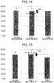
- the second measurement value is 5% lower than the first measurement value (reference measurement value A) because of the effect of fading due to overlapping irradiation areas, for example.
- the first measurement value (reference measurement value A) would also be 5% lower than a proper measurement value. Accordingly, as illustrated in Fig. 14 , there is substantially no difference between the first measurement value (reference measurement value A) and the second measurement value (comparison measurement value B). Therefore, when the first measurement value and the second and subsequent measurement values are the same, it might be determined to be a normal measurement.
- This case can be handled, for example, by calculating a coefficient of 95% on the basis of the fading rate of the fluorescent substance and on the basis of the area of the overlapping portion in the irradiation area, and then, as illustrated by the arrow in Fig. 14 so as to lower the reference measurement value A being 100% to 95%.
- the reference measurement value A becomes lower than the comparison measurement value B (A ⁇ B), leading to determination of abnormal measurement.
- this correction even in a case where the fluorescent substance easily fades, it is also possible to accurately perform measurement abnormality determination even with a relatively small foreign body included in the first irradiation area E1.
- Example 6 will be described as a case where there is unevenness in the amount of the primary antibody that traps an analyte in a plane of the reaction field 8 and where a fluorescent substance labeled to the antigen would not easily fade.
- the fading rate of the fluorescent substance is low, it is difficult to make a difference between the first measurement value and the second measurement value even when the first irradiation area E1 and the second irradiation area E2 partially overlap.
- the first measurement value and the second measurement value are substantially equal as illustrated in Fig. 15 .
- the first measurement value would become lower than the second measurement value even without the presence of the bubble BU, leading to false positive determination of measurement abnormality.
- the first measurement value will be multiplied by a coefficient calculated in consideration of the assumed amount of unevenness of the primary antibody amount, namely, a coefficient 110% exceeding 100%, for example, so as to perform correction for raising the reference measurement value A as illustrated by an arrow in Fig. 14 .
- a coefficient 110% exceeding 100% for example, so as to perform correction for raising the reference measurement value A as illustrated by an arrow in Fig. 14 .
- the present embodiment of the invention it is possible to detect the measurement abnormality on the basis of the measurement result obtained by the light measurement means 18. Therefore, it is necessary to mount a camera or other optical systems for detecting the measurement abnormality. This makes it possible to easily detect the measurement abnormality without increasing load in hardware.
- the determination of the measurement abnormality is made using the light amount of the fluorescence FL measured by the light measurement means 18 instead of grasping the position or the like of the bubble BU successively using a camera or the like.
- this method it is possible to determine even an abnormality during the reaction, such as hindrance of binding of the primary antibody and antigen due to the bubble BU when the bubble BU is not contained in the measurement area at the measurement.
- the present embodiment of the invention it is possible to provide a measuring device and a measurement abnormality detecting method capable of easily detecting a measurement abnormality occurring during measurement or reaction without increasing load in hardware.
- Fig. 16 is a view illustrating specific positions of the bubble BU in a case where no measurement abnormality is determined in the above embodiment.
- the measurement would not be influenced by the bubble BU.
- the position of the bubble BU is shifted rightward from the first irradiation area E1
- the measurement would not be influenced by the bubble BU.
- the position of the bubble BU is slightly overlapped with the first irradiation area E1, but this would not influence the measurement so much since it is displaced upward.
- Fig. 16(d) since the bubble BU is small and its position is shifted rightward from the first irradiation area E1, the measurement would not be influenced by the bubble BU.
- the measurement may be performed three or more times. For example, it is allowable to first move the chip structure 12 in the X direction and perform measurement of the light intensity of the fluorescence FL three times, and thereafter move the chip structure 12 in a Y direction (direction orthogonal to the X direction) across the first irradiation area E1, and in this state, it is possible to perform the measurement of the light amount of the fluorescence FL twice more so as to perform a total of five times of measurement. In this manner, it is allowable to perform the measurement two-dimensionally.
- the above-described embodiment is an example where the bubble BU is included in the first irradiation area E1 as the measurement inhibition factor.
- the measurement inhibition factor may be a foreign body such as fibrin or dust. Even when foreign body is present, the measurement value decreases in accordance with the size of foreign body like the bubble BU.
- the above-described embodiment is an exemplary case where the position of the chip structure 12 is moved by the driving means 31 to allow the measurement varied irradiation area positions.
- the driving means 31 to move the light emission means 14 to perform the measurement.
- measurement may be performed by moving both the chip structure 12 and the light emission means 14.
- the light measurement means 18 may also be moved to perform the measurement.
- the measuring device 2 for SPFS is described as an example.
- the measuring device and the measurement abnormality detecting method of the present invention are not limited to the SPFS.
- the present invention includes as an aspect; a program for causing a computer to execute the above-described measurement abnormality detection; and a computer-readable recording medium such as a magnetic tape (digital data storage (DSS)), a magnetic disk (hard disk drive (HDD), a flexible disk (FD), etc.), an optical disk (a compact disk (CD), a digital versatile disk (DVD), a Blu-ray disk (BD), etc.), a magneto optical disk (MO), a flash memory (Solid State Drive (SSD), a memory card, a USB memory, etc.).
- DSS digital data storage
- HDD hard disk drive
- FD flexible disk
- FD flexible disk
- an optical disk a compact disk (CD), a digital versatile disk (DVD), a Blu-ray disk (BD), etc.
- MO magneto optical disk
- SSD Solid State Drive
- memory card a USB memory, etc.
Landscapes
- Health & Medical Sciences (AREA)
- Chemical & Material Sciences (AREA)
- Immunology (AREA)
- Physics & Mathematics (AREA)
- General Health & Medical Sciences (AREA)
- Pathology (AREA)
- Analytical Chemistry (AREA)
- Biochemistry (AREA)
- Life Sciences & Earth Sciences (AREA)
- General Physics & Mathematics (AREA)
- Nuclear Medicine, Radiotherapy & Molecular Imaging (AREA)
- Engineering & Computer Science (AREA)
- Textile Engineering (AREA)
- Chemical Kinetics & Catalysis (AREA)
- Optics & Photonics (AREA)
- Investigating, Analyzing Materials By Fluorescence Or Luminescence (AREA)
- Optical Measuring Cells (AREA)
- Investigating Or Analysing Materials By Optical Means (AREA)
- Measurement Of Radiation (AREA)
Abstract
Description
- The present invention relates to a measuring device, a measurement abnormality detecting method, and a program for determining measurement abnormality when measurement of a measurement target is inhibited by a bubble, a foreign body, or the like.
- Conventionally, there are many techniques for detecting measurement abnormality. A known example of these techniques is an electrolytic analyzer that determines bubble noise abnormality caused by a bubble entering a specimen channel at ion concentration measurement (refer to
Patent Literature 1, for example). This electrolytic analyzer determines bubble noise abnormality when a difference in ion concentration of internal standard solution before and after specimen measurement exceeds a reference value. - However, since this electrolytic analyzer is based on the use of internal standard solution, it is difficult to measure the concentration of a substance having a wide concentration range that is not predictable, even though it would be possible to measure the concentration of a substance whose concentration range is known. In a case where it is difficult to use the internal standard solution in this manner, it is necessary to judge measurement abnormality using same samples.
- Here, as a conventional example in which measurement abnormality using the same sample is performed, a method using scattered light is known (for example, refer to Patent Literature 2). While this method using scattered light can measure reaction as a great change as compared with the method of measuring the transmitted light, this method has a disadvantage that it is easily influenced by foreign body reaction. Examples of the foreign body reaction include growth of a bubble on an optical path due to precipitation of dissolved oxygen, nonspecific agglutination reaction of foreign body contained in the blood, and nonspecific agglutination reaction of dirt contained in the reaction solution.
- Note that this method using scattered light is a method applicable with the presence of a phenomenon peculiar to scattering, and thus, is not applicable in an apparatus that uses a measurement method other than the scattering method. In addition, in order to utilize the characteristics of scattered light, a plurality of light receivers corresponding to angles are needed, increasing the load on the apparatus.
- For this reason, it is preferable to provide a means capable of determining the measurement abnormality without using scattered light. As a specific example of this means, there is also known a foreign body detector that observes inside of a channel with a camera and identifies a foreign body (for example, refer to Patent Literature 3). This foreign body detector determines whether a target object is a foreign object or a bubble on the basis of the shape of the target object observed in the channel.
-
- Patent Literature 1:
JP 2014-41060 A - Patent Literature 2:
JP 2014-21008 A - Patent Literature 3:
JP 2008-102027 A - The foreign body detector described above, however, leads to an increase in the burden in development of analysis software in addition to an increase in the load in hardware. Moreover, since the above-described foreign body detection means detects a moment of presence of a foreign body, it would be difficult to detect the foreign body during reaction merely by detection at measurement. In order to detect a foreign body during reaction, there is a need to keep monitoring constantly during the reaction, increasing the load. Furthermore, observation during reaction or measurement need preparation of a special arrangement relationship between the original reaction apparatus, measuring device and foreign body detector, or the like.
- An object of the present invention is to provide a measuring device, a measurement abnormality detecting method, and a program capable of easily detecting measurement abnormality without increasing load in hardware.
- In order to achieve at least one of the above objects, a measuring device, a measurement abnormality detecting method, and a program reflecting one aspect of the present invention include the following items.
- A measuring device including:
an emission means that emits light to a measurement target region; a light measurement means that measures light output from the measurement target region by emission with the emission means; a driving means that moves a position of at least one of the measurement target region and the emission means; and a determination means that compares measurement values of the light measured a plurality of times by the light measurement means while changing positions of the measurement target region by the driving means and thereby determines abnormality of a measurement result, in which the determination means determines measurement abnormality in a case where a reference measurement value being a measurement value obtained for a first time is lower than a comparison measurement value being a highest measurement value among measurement values obtained for second and subsequent times. - A measurement abnormality detecting method including:
a light measurement step of emitting light to a measurement target region and thereby measuring light output from the measurement target region; and a determination step of comparing measurement values of the light measured a plurality of times while changing positions of the measurement target region and thereby determining abnormality of a measurement result, in which the determination step determines measurement abnormality in a case where a reference measurement value being a measurement value obtained for a first time is lower than a comparison measurement value being a highest measurement value among measurement values obtained for second and subsequent times. - A program causing a computer to execute functions including:
a light measurement function of emitting light to a measurement target region and thereby measuring light output from the measurement target region; and a determination function of comparing measurement values of the light measured a plurality of times while changings position of the measurement target region and thereby determining abnormality of a measurement result, in which the determination function determines measurement abnormality in a case where a reference measurement value being a measurement value obtained for a first time is lower than a comparison measurement value being a highest measurement value among measurement values obtained for second and subsequent times. - According to the present invention, it is possible to provide a measuring device, a measurement abnormality detecting method, and a program capable of easily detecting measurement abnormality without increasing load in hardware.
-
-
Fig. 1 is a view illustrating a configuration of a measuring device according to an embodiment. -
Fig. 2 is a top view of a chip structure according to the embodiment. -
Fig. 3 is a view illustrating a position of an irradiation area and a measurement result of fluorescence according to the embodiment. -
Fig. 4 is a view illustrating a position of an irradiation area and a measurement result of fluorescence according to a modified example of the embodiment. -
Fig. 5 is a graph indicating comparison of the light amount of fluorescence varying depending on size of a bubble. -
Fig. 6 is a top view of a chip structure having a bubble included in a channel. -
Fig. 7 is a graph illustrating a relationship between size of a bubble included in the irradiation area and the light amount of fluorescence according to the embodiment. -
Fig. 8 is a view illustrating a position of an irradiation area and a measurement result of fluorescence in Example 1. -
Fig. 9 is a view illustrating a position of an irradiation area and a measurement result of fluorescence in Example 2. -
Fig. 10 is a view illustrating a position of an irradiation area and a measurement result of fluorescence in Example 3. -
Fig. 11 is a view illustrating a position of an irradiation area and a measurement result of fluorescence in Example 4. -
Fig. 12 is a view illustrating a position of an irradiation area and a measurement result of fluorescence in a modification of Example 4. -
Fig. 13 is a view illustrating a position of an irradiation area and a bubble in Example 5. -
Fig. 14 is a diagram illustrating a measurement result of Example 5. -
Fig. 15 is a diagram illustrating a measurement result of Example 6. -
Fig. 16 is a view illustrating a specific example of positions of a bubble in a case where no measurement abnormality determination is made in the measuring device according to the embodiment. - Hereinafter, a measuring device according to an embodiment of the present invention will be described with reference to the drawings using a measuring device for surface plasmon field-enhanced fluorescence spectroscopy (SPFS) as an example.
Fig. 1 is a view illustrating a configuration of ameasuring device 2 according to the present embodiment. As illustrated inFig. 1 , themeasuring device 2 includes achip structure 12 having a metalthin film 6 provided on a surface of a prism 4 which is a dielectric member and having areaction field 8 and aliquid port 10 provided on a surface of the metalthin film 6. - The
measuring device 2 further includes, on the prism 4 side of the chip structure 12: an emission means 14 that emits excitation light EL incident into the prism 4 to be directed toward the metalthin film 6; and alight receiving means 16 that receives reflected light RL, that is, light emitted from the emission means 14 and reflected by the metalthin film 6. - On the
reaction field 8 side of thechip structure 12, there is provided a light measurement means 18 that measures light amount of fluorescence FL emitted from a fluorescent substance described below. Between thereaction field 8 and the light measurement means 18, alight collecting member 20 and afilter 22 are provided. - The
measuring device 2 further includes: a driving means 31 moves the position of thechip structure 12; and a control means 33 that integrally controls individual portions of themeasuring device 2. The control means 33 (determination means) performs determination of measurement abnormality of the fluorescence FL measured by the light measurement means 18 and control of the driving means 31, or the like. - Here, before the measurement is performed, primary antibody solution containing primary antibody is supplied to a
channel 24, the primary antibody is immobilized to thereaction field 8, and the primary antibody solution is recovered from thechannel 24. Subsequently, a specimen solution containing an antigen such as protein is supplied to thechannel 24, the antigen is bound to the primary antibody, and the specimen liquid is recovered from thechannel 24. Next, a secondary antibody solution containing a secondary antibody labeled with a fluorescent substance is supplied to thechannel 24, and the secondary antibody is bound to the antigen. - When the measurement is performed, the excitation light EL is guided to be incident on the prism 4. The excitation light EL incident on the prism 4 is reflected at an interface between the metal
thin film 6 and the prism 4, and exits from the prism 4 as the reflected light RL. The incident angle of the excitation light EL to the interface between the metalthin film 6 and the prism 4 is set to a resonance angle θ1. - During emission of the excitation light EL to the prism 4, an evanescent wave leaks from the interface between the metal
thin film 6 and the prism 4 to the metalthin film 6 side, allowing resonance between the evanescent wave and the plasmon on the surface of the metalthin film 6. This enhances an electric field of the evanescent wave. This enhanced electric field acts on the fluorescent substance, and the fluorescence FL is emitted from thereaction field 8. The light amount of the fluorescence FL is measured by the light measurement means 18. Subsequently, the presence or absence of an antigen, a trapping amount of an antigen, or the like, are obtained from the light amount of the fluorescence FL. - Next, a measurement abnormality detecting method of determining measurement abnormality of the fluorescence FL using the
measuring device 2 according to the present embodiment will be described using an exemplary case where it is determined that a measurement result is accurate.Fig. 2 is a top view of thechip structure 12.Fig. 3 is a view illustrating positions of irradiation areas in thereaction field 8 to which excitation light is emitted and a measurement result of fluorescence. Description of the present embodiment will use an exemplary case where the driving means 31 moves thechip structure 12 in the X direction and the light amount of the fluorescence FL is measured three times (light measurement step). First, as illustrated inFig. 3(a) , at a first time, the excitation light EL is emitted to a first irradiation area E1 located at a center in the X direction of thereaction field 8, and then, the light amount of the fluorescence FL emitted from the first irradiation area E1 and transmitted through thelight collecting member 20 and thefilter 22 is measured by the light measurement means 18 (first measurement). - At a second time, the position of the
chip structure 12 is moved in the -X direction by the driving means 31. The excitation light EL is emitted to a second irradiation area E2 located at a bottom of thereaction field 8 inFig. 3(a) (hereinafter referred to as the bottom), and then, the light amount of the fluorescence FL emitted from the second irradiation area E2 is measured by the light measurement means 18 (second measurement). - Here, in the second measurement, measurement is performed so that the lower part of the second irradiation area E2 overlaps with the first irradiation area E1. Note that the fluorescent substance that labels the antigen has a property that the color fades (fading property) every time the substance is irradiated with the excitation light EL. Therefore, as illustrated in the graph of
Fig. 3(b) , when a measurement value of the light amount of the fluorescence FL obtained in the first measurement (hereinafter abbreviated as the measurement value) is 100%, the measurement value obtained at the second measurement is a little more than 80%. Note that as illustrated inFig. 4 , when measurement is performed without overlapping irradiation areas, the fluorescent substance would not fade, and thus, all measurement values are the same value. - At a third time, the position of the
chip structure 12 is moved in the +X direction by the driving means 31. The excitation light EL is emitted to a third irradiation area E3 located at a top of thereaction field 8 inFig. 3(a) (hereinafter referred to as the top), and then, the light amount of the fluorescence FL emitted from the third irradiation area E3 is measured by the light measurement means 18 (third measurement). - Note that, in the present embodiment, a movement amount of the
chip structure 12 in the X direction at the second and third measurements is set in consideration of the size of thereaction field 8, the size of the irradiation area, and a position error between thereaction field 8 and the first irradiation area E1. - For example, here is an exemplary case where the size of the
reaction field 8 is not sufficient compared with the size of the irradiation area, being a case where the size of thereaction field 8 is less than three times the size of the irradiation area, for example. In this case, the movement amount of thechip structure 12 in the X direction is reduced to be smaller than the size of the first irradiation area E1 so as to allow the first irradiation area E1 and the second irradiation area E2 to partially overlap with each other as illustrated inFig. 3(a) , for example. - With this arrangement, even when the first irradiation area E1 is slightly displaced from the center of the
reaction field 8, at least one of the second irradiation area E2 and the third irradiation area E3 is substantially included in thereaction field 8. This makes it possible to correctly obtain comparison measurement values described below, leading to achievement of detection of measurement abnormality with high accuracy. - In contrast, here is an exemplary case where the size of the
reaction field 8 is sufficient compared with the size of the irradiation area, being a case where the size of thereaction field 8 three times the size of the irradiation area, or more, for example. In this case, the movement amount of thechip structure 12 in the X direction is increased to be larger than the size of the first irradiation area E1 so as to suppress overlapping of the first irradiation area E1 and the second irradiation area E2 as illustrated inFig. 4(a) , for example. This would eliminate the influence of fading of the fluorescent substance, making it possible to detect the measurement abnormality with higher accuracy. - Furthermore, it is desirable that the movement amount of the
chip structure 12 in the X direction be at least 0.5 times the size of the irradiation area. With the setting of the movement amount of thechip structure 12 in the X direction to be less than 0.5 times the size of the irradiation area, three areas, that is, the first irradiation area E1, the second irradiation area E2, and the third irradiation area E3 might overlap with each other. Overlapping of the three irradiation areas might greatly increase an influence of fading of the fluorescent substance in the overlapping irradiation area, and this might degrade measurement abnormality detection accuracy. - After the third measurement, the control means 33 determines whether the light amount is measured normally (determination step). Specifically, first, the first measurement value is compared with a highest measurement value among the measurement values obtained for second and subsequent times. Here, the first measurement value is a measurement value serving as a measurement reference, which is going to be a measurement value of this measurement. A reason for adopting the first measurement value as a result of this measurement is because the measurement values obtained in the second and subsequent times include influence of dissociation of the antigen antibody and fading of the fluorescent substance. Accordingly, in the following description, the first measurement value is defined as a reference measurement value A, and the highest measurement value among the measurement values obtained for the second and subsequent times is set as a comparison measurement value B.
- In a case where the reference measurement value A is lower than the comparison measurement value B (A < B), determination of measurement abnormality is made. In a case where the reference measurement value A is not lower than the comparison measurement value B (A ≥ B), determination of normal measurement is made. In the case illustrated in
Fig. 3(a) , since the reference measurement value A is higher than the comparison measurement value B (A ≥ B), determination of normal measurement is made. Note that the measurement in the present embodiment is directed to a measurement value being a detection limit or above. The detection limit represents a minimum detectable amount and is also referred to as a lower detection limit. This means, in typical usage, the minimum concentration that can be separated from the blank measurement value including variation. - Next, a case where determination of measurement abnormality is made will be described. The determination of the measurement abnormality is made mainly in a case where an inhibition factor that inhibits reaction or measurement, such as a bubble or foreign body, is located in the irradiation area and this lowers the light amount of the fluorescence FL to be measured.
-
Fig. 5 is a graph comparing light amounts of the fluorescence FL varying with the bubble size. Here, s1 illustrated inFig. 5 is a light amount change rate in a case where the fluorescence FL is measured while the chip structure 12 (refer toFig. 2 ) not including a bubble is moved in the +X direction. In contrast, s2, s3 and s4 are light amount change rates in a case where the fluorescence FL is measured while three types ofchip structure 12 are moved in the +X direction. Specifically, s2 is a case using the chip structure 12 (refer toFig. 6(a) in which a bubble BU of ϕ 1.8 mm is included in thechannel 24; s3 is a case using the chip structure 12 (refer toFig. 6(b) in which a bubble BU of ϕ 1.5 mm is included in thechannel 24; and s4 is a case using the chip structure 12 (refer toFig. 6(c) in which a bubble BU of ϕ 1.0 mm is included in thechannel 24. The size of the irradiation area was ϕ 1.5 mm. - As illustrated in
Fig. 5 , the greater the size of the bubble BU, the lower the light amount of the fluorescence FL. Here, in S2 (ϕ 1.8 mm) where the size of the bubble BU is greater than the size of the irradiation area and in S3 (ϕ 1.5 mm) where the size of the bubble BU is equivalent to the irradiation area, it is observed that the light amount of the fluorescence FL decreases by 90% or more at the position where the bubble BU and the irradiation area substantially overlap each other. -
Fig. 7 is a graph illustrating a relationship between the size of the bubble BU included in the irradiation area and the light amount of the fluorescence FL. As illustrated inFig. 7 , it is observed that the size of the bubble BU and the decrease rate of the light amount of the fluorescence FL are substantially proportional and that the decrease rate is 100% when the size of the bubble BU is substantially equal to the size of the irradiation area. - The following is description of Examples in a case where determination of measurement abnormality is made because bubble BU is included in the first irradiation area E1. Note that Examples include measurements performed for the second and third times in a state where the irradiation areas were shifted by 0.8 mm in the X direction after completion of the first main measurement. In Examples 1 to 4, determination of the reference measurement value A is made without correcting the value by a coefficient to be described below.
-
Fig. 8 is a view illustrating a position of the irradiation area and a fluorescence measurement result in a case where the measurement is performed by the same procedure as described with reference toFig. 3 . In Example 1, inclusion of the bubble BU in the first irradiation area E1 as illustrated inFig. 8(a) causes reduction of the light amount of the fluorescence FL measured in the first measurement. For this reason, as illustrated inFig. 8(b) , the reference measurement value A is lower than the comparison measurement value B (A < B), leading to a determination of measurement abnormality. - As illustrated in
Fig. 9(a) , Example 2 is a measurement example in which the first irradiation area E1 is shifted downward in the center of thereaction field 8 in the first measurement. In this case, the second irradiation area E2 and the third irradiation area E3 are also shifted downward. A substantial part of the second irradiation area E2 is located in a portion deviating from the reaction field 8 (portion where no fluorescent substance is present). Therefore, as illustrated inFig. 9(b) , the value obtained by the second measurement is significantly lower than the measurement value obtained by the third measurement, and the measurement value obtained by the third measurement is to be the comparison measurement value B. Here, since the bubble BU is included in the first irradiation area E1 and this decreases the light amount of the fluorescence FL obtained in the first measurement. This results in the reference measurement value A lower than the comparison measurement value B (A < B), leading to determination of measurement abnormality. - As illustrated in
Fig. 10(a) , Example 3 is a measurement example in which the first irradiation area E1 is shifted upward from the center of thereaction field 8 in the first measurement, as opposed to the Example 2. In this case, the second irradiation area E2 and the third irradiation area E3 are also shifted upward. A substantial part of the third irradiation area E3 is located in a portion deviating from thereaction field 8. Therefore, as illustrated inFig. 10(b) , the value obtained in the third measurement is significantly lower than the measurement value obtained in the second measurement, and the measurement value obtained in the second measurement is to be the comparison measurement value B. Here, the reference measurement value A obtained by the measurement of the first irradiation area E1 including the bubble BU is lower than the comparison measurement value B (A < B), leading to determination of measurement abnormality. - Example 4 is a measurement example in the case where the irradiation area of Example 1 is shifted leftward from the center of the
reaction field 8, as illustrated inFig. 11(a) . In this case, since a part of each of the second irradiation area E2 and the third irradiation area E3 deviates from thereaction field 8, measurement values obtained in the second and third measurements are lower than the measurement values in a case where the second irradiation area E2 and the third irradiation area E3 are located within thereaction field 8. On the other hand, since the bubble BU is included in the first irradiation area E1, the first measurement value also decreases as compared with the case where the bubble BU is not included. In Example 4, as illustrated inFig. 11(b) , because the reference measurement value A is lower than the comparison measurement value B (A < B), leading to determination of measurement abnormality. - While the above describes exemplary cases in which determination of measurement abnormality is made using Examples 1 to 4 as specific examples, there may be a case where accurate determination is difficult even when measurement is performed as indicated in Examples 1 to 4. For example, in a case where the bubble BU of Example 4 is small as illustrated in
Fig. 12(a) , the reference measurement value A becomes slightly higher than the comparison measurement value B, leading to determination of normal measurement, as illustrated inFig. 12(b) . In such a case, correction is performed by multiplying the reference measurement value A by a coefficient so as to increase the accuracy in measurement abnormality determination. The coefficient is calculated from an area of a portion having mutually overlapping irradiation areas and from the degree of fading property of the fluorescent substance (hereinafter referred to as fading rate). The higher the fading rate of the fluorescent substance, the smaller the coefficient; the lower the fading rate of the fluorescent substance, the greater the coefficient. Moreover, the larger the area of an overlapping portion where the first irradiation area E1 being a measurement target and another irradiation area overlap with each other, the smaller the coefficient. The smaller the area of the overlapping portion, the greater the coefficient. - In Example 5, a measurement example in a case where the reference measurement value A is corrected by using a coefficient will be described. Here,
Fig. 13 is a view illustrating positions of the irradiation area on thechip structure 12 and the bubble BU at the light amount measurement of the fluorescence FL. In addition, in thereaction field 8 of Example 5, a fluorescent substance having a fading rate higher than a predetermined fading rate (that is, easy to fade) is used for the labeling the antigen. - Here is an exemplary case where determination of the measurement abnormality is made without performing correcting by a coefficient under a normal state in which no bubbles are included in the first irradiation area E1. In this situation, the second measurement value (comparison measurement value B) is 5% lower than the first measurement value (reference measurement value A) because of the effect of fading due to overlapping irradiation areas, for example.
- In this case, if measurements are performed in a state where a bubble is included in the first irradiation area E1, and in a case where the size of the bubble BU is relatively small and the degree of influence is about 5%, the first measurement value (reference measurement value A) would also be 5% lower than a proper measurement value. Accordingly, as illustrated in
Fig. 14 , there is substantially no difference between the first measurement value (reference measurement value A) and the second measurement value (comparison measurement value B). Therefore, when the first measurement value and the second and subsequent measurement values are the same, it might be determined to be a normal measurement. - This case can be handled, for example, by calculating a coefficient of 95% on the basis of the fading rate of the fluorescent substance and on the basis of the area of the overlapping portion in the irradiation area, and then, as illustrated by the arrow in
Fig. 14 so as to lower the reference measurement value A being 100% to 95%. With this operation, the reference measurement value A becomes lower than the comparison measurement value B (A < B), leading to determination of abnormal measurement. With this correction, even in a case where the fluorescent substance easily fades, it is also possible to accurately perform measurement abnormality determination even with a relatively small foreign body included in the first irradiation area E1. - Example 6 will be described as a case where there is unevenness in the amount of the primary antibody that traps an analyte in a plane of the
reaction field 8 and where a fluorescent substance labeled to the antigen would not easily fade. First, in a case where the fading rate of the fluorescent substance is low, it is difficult to make a difference between the first measurement value and the second measurement value even when the first irradiation area E1 and the second irradiation area E2 partially overlap. In an ideal state where there is no unevenness in the amount of the primary antibody that traps the analyte in the plane of thereaction field 8 in particular, the first measurement value and the second measurement value are substantially equal as illustrated inFig. 15 . However, in a case where there is unevenness in the concentration for trapping the analyte in the plane of thereaction field 8, and the second irradiation area E2 has trapped an analyte having a higher concentration than the first irradiation area E1, the first measurement value would become lower than the second measurement value even without the presence of the bubble BU, leading to false positive determination of measurement abnormality. - In order to handle this case, the first measurement value will be multiplied by a coefficient calculated in consideration of the assumed amount of unevenness of the primary antibody amount, namely, a coefficient 110% exceeding 100%, for example, so as to perform correction for raising the reference measurement value A as illustrated by an arrow in
Fig. 14 . With this correction, it is possible to accurately perform measurement abnormality determination even when there is unevenness in the amount of the primary antibody that traps the analyte in the plane of thereaction field 8 and when the fluorescent substance would not easily fade. - According to the present embodiment of the invention, it is possible to detect the measurement abnormality on the basis of the measurement result obtained by the light measurement means 18. Therefore, it is necessary to mount a camera or other optical systems for detecting the measurement abnormality. This makes it possible to easily detect the measurement abnormality without increasing load in hardware.
- In addition, with execution of determination by multiplying the reference measurement value A by a coefficient, it is possible to accurately determine measurement abnormality for a relatively small foreign body in a system with large amount of fading of a fluorescent substance or a system having uneven trapping concentration in a reaction field. For this reason, for example, it would be possible to appropriately prevent a situation in which negative judgment is erroneously made (false negative) by detection of a low measurement value even though the antigen should be positive, as a result of failure in performing normal reaction or measurement due to the presence of the bubble BU in the
reaction field 8. - Furthermore, the determination of the measurement abnormality is made using the light amount of the fluorescence FL measured by the light measurement means 18 instead of grasping the position or the like of the bubble BU successively using a camera or the like. With this method, it is possible to determine even an abnormality during the reaction, such as hindrance of binding of the primary antibody and antigen due to the bubble BU when the bubble BU is not contained in the measurement area at the measurement.
- That is, according to the present embodiment of the invention, it is possible to provide a measuring device and a measurement abnormality detecting method capable of easily detecting a measurement abnormality occurring during measurement or reaction without increasing load in hardware.
- Additionally,
Fig. 16 is a view illustrating specific positions of the bubble BU in a case where no measurement abnormality is determined in the above embodiment. InFig. 16(a) , since the position of the bubble BU is shifted upward from the first irradiation area E1, the measurement would not be influenced by the bubble BU. Furthermore, inFig. 16(b) , since the position of the bubble BU is shifted rightward from the first irradiation area E1, the measurement would not be influenced by the bubble BU. InFig. 16(c) , the position of the bubble BU is slightly overlapped with the first irradiation area E1, but this would not influence the measurement so much since it is displaced upward. InFig. 16(d) , since the bubble BU is small and its position is shifted rightward from the first irradiation area E1, the measurement would not be influenced by the bubble BU. - While the above-described embodiment moves the
chip structure 12 in the X direction to measure the light amount of the fluorescence FL three times, the measurement may be performed three or more times. For example, it is allowable to first move thechip structure 12 in the X direction and perform measurement of the light intensity of the fluorescence FL three times, and thereafter move thechip structure 12 in a Y direction (direction orthogonal to the X direction) across the first irradiation area E1, and in this state, it is possible to perform the measurement of the light amount of the fluorescence FL twice more so as to perform a total of five times of measurement. In this manner, it is allowable to perform the measurement two-dimensionally. With this configuration, for example, even in a case where bubbles are aligned in the X direction and it would difficult to determine the measurement abnormality by three measurements with the irradiation area shifted in the X direction, it is possible to define the measurement value obtained by shifting the irradiation area in the Y direction, namely, direction with no presence of the bubble as the comparison measurement value B. This makes it possible to accurately determine the measurement abnormality. - The above-described embodiment is an example where the bubble BU is included in the first irradiation area E1 as the measurement inhibition factor. However, the measurement inhibition factor may be a foreign body such as fibrin or dust. Even when foreign body is present, the measurement value decreases in accordance with the size of foreign body like the bubble BU.
- Furthermore, the above-described embodiment is an exemplary case where the position of the
chip structure 12 is moved by the driving means 31 to allow the measurement varied irradiation area positions. However, it is also allowable to use the driving means 31 to move the light emission means 14 to perform the measurement. Alternatively, measurement may be performed by moving both thechip structure 12 and the light emission means 14. Furthermore, in a case where the light measuring position would be shifted by moving the light emission means 14, the light measurement means 18 may also be moved to perform the measurement. - In the above-described embodiment, the measuring
device 2 for SPFS is described as an example. However, the measuring device and the measurement abnormality detecting method of the present invention are not limited to the SPFS. - Furthermore, the present invention includes as an aspect; a program for causing a computer to execute the above-described measurement abnormality detection; and a computer-readable recording medium such as a magnetic tape (digital data storage (DSS)), a magnetic disk (hard disk drive (HDD), a flexible disk (FD), etc.), an optical disk (a compact disk (CD), a digital versatile disk (DVD), a Blu-ray disk (BD), etc.), a magneto optical disk (MO), a flash memory (Solid State Drive (SSD), a memory card, a USB memory, etc.).
-
- 2
- Measuring device
- 4
- Prism
- 6
- Metal thin film
- 8
- Reaction field
- 12
- Chip structure
- 14
- Emission means
- 16
- Light receiving means
- 18
- Light measurement means
- 20
- Light collecting member
- 22
- Filter
- 24
- Channel
- 31
- Driving means
- 33
- Control means
- EL
- Excitation light
- FL
- Fluorescence
- RL
- Reflected light
Claims (18)
- A measuring device comprising:an emission means that emits light to a measurement target region;a light measurement means that measures light output from the measurement target region by emission with the emission means;a driving means that moves a position of at least one of the measurement target region and the emission means; anda determination means that compares measurement values of the light measured a plurality of times by the light measurement means while changing positions of the measurement target region by the driving means and thereby determines abnormality of a measurement result, whereinthe determination means determines measurement abnormality in a case where a reference measurement value being a measurement value obtained for a first time is lower than a comparison measurement value being a highest measurement value among measurement values obtained for second and subsequent times.
- The measuring device according to claim 1,
wherein a first irradiation area irradiated in a first measurement out of irradiation areas within the measurement target region irradiated by the emission means partially overlaps with another irradiation area irradiated in measurement of second and subsequent times. - The measuring device according to claim 1 or 2,
wherein irradiation by the emission means is performed three or more times across the first irradiation area. - The measuring device according to any one of claims 1 to 3,
wherein the determination means uses the reference measurement value corrected by using a predetermined coefficient at a time of determination of measurement abnormality. - The measuring device according to any one of claims 1 to 4,
wherein the measurement target region is a reaction field in which a biochemical reaction is performed, and
the measurement result is calculated from amount of light emitted from a fluorescent substance positioned in the reaction field. - The measuring device according to claim 5,
wherein the predetermined coefficient is calculated by using an area of a portion in which the first irradiation area overlaps with the other irradiation area and using a fading rate of the fluorescent substance. - The measuring device according to any one of claims 1 to 6,
wherein the measurement inhibition factor causing the measurement abnormality is one of a bubble or a foreign body. - The measuring device according to any one of claims 1 to 7,
wherein determination by the determination means is directed to a measurement value of the light amount, being a detection limit or above. - A measurement abnormality detecting method comprising:a light measurement step of emitting light to a measurement target region and thereby measuring light output from the measurement target region; anda determination step of comparing measurement values of the light measured a plurality of times while changing positions of the measurement target region and thereby determining abnormality of a measurement result, whereinthe determination step determines measurement abnormality in a case where a reference measurement value being a measurement value obtained for a first time is lower than a comparison measurement value being a highest measurement value among measurement values obtained for second and subsequent times.
- The measurement abnormality detecting method according to claim 9,
wherein a first irradiation area irradiated in a first measurement out of irradiation areas within the measurement target region partially overlaps with another irradiation area irradiated in measurement of second and subsequent times. - The measurement abnormality detecting method according to claim 9 or 10,
wherein irradiation of the measurement target region is performed three or more times across the first irradiation area. - The measurement abnormality detecting method according to any one of claims 9 to 11,
wherein the determination step uses the reference measurement value corrected by using a predetermined coefficient at a time of determination of measurement abnormality. - The measurement abnormality detecting method according to any one of claims 9 to 12,
wherein the measurement target region is a reaction field in which a biochemical reaction is performed, and
the measurement result is calculated from amount of light emitted from a fluorescent substance positioned in the reaction field. - The measurement abnormality detecting method according to claim 13,
wherein the predetermined coefficient is calculated by using an area of a portion in which the first irradiation area overlaps with the other irradiation area and using a fading rate of the fluorescent substance. - The measurement abnormality detecting method according to any one of claims 9 to 14,
wherein the measurement inhibition factor causing the measurement abnormality is one of a bubble or foreign body. - The measurement abnormality detecting method according to any one of claims 9 to 15,
wherein determination by the determination means is directed to a measurement value of the light amount, being a detection limit or above. - A program causing a computer to execute functions comprising:a light measurement function of emitting light to a measurement target region and thereby measuring light output from the measurement target region; anda determination function of comparing measurement values of the light measured a plurality of times while changings position of the measurement target region and thereby determining abnormality of a measurement result, whereinthe determination function determines measurement abnormality in a case where a reference measurement value being a measurement value obtained for a first time is lower than a comparison measurement value being a highest measurement value among measurement values obtained for second and subsequent times.
- A computer-readable recording medium on which the program according to claim 17 is recorded.
Applications Claiming Priority (2)
| Application Number | Priority Date | Filing Date | Title |
|---|---|---|---|
| JP2016239297 | 2016-12-09 | ||
| PCT/JP2017/043635 WO2018105607A1 (en) | 2016-12-09 | 2017-12-05 | Measuring device, measurement abnormality detecting method, and program |
Publications (3)
| Publication Number | Publication Date |
|---|---|
| EP3553501A1 true EP3553501A1 (en) | 2019-10-16 |
| EP3553501A4 EP3553501A4 (en) | 2019-12-11 |
| EP3553501B1 EP3553501B1 (en) | 2022-07-20 |
Family
ID=62491112
Family Applications (1)
| Application Number | Title | Priority Date | Filing Date |
|---|---|---|---|
| EP17877866.8A Active EP3553501B1 (en) | 2016-12-09 | 2017-12-05 | Measurement abnormality detecting method |
Country Status (5)
| Country | Link |
|---|---|
| US (1) | US11397150B2 (en) |
| EP (1) | EP3553501B1 (en) |
| JP (1) | JP7034087B2 (en) |
| ES (1) | ES2927479T3 (en) |
| WO (1) | WO2018105607A1 (en) |
Family Cites Families (21)
| Publication number | Priority date | Publication date | Assignee | Title |
|---|---|---|---|---|
| US5547849A (en) | 1993-02-17 | 1996-08-20 | Biometric Imaging, Inc. | Apparatus and method for volumetric capillary cytometry |
| JP2000516719A (en) * | 1996-08-16 | 2000-12-12 | ツェプトゼンス アクチエンゲゼルシャフト | Photodetector |
| JP4132046B2 (en) * | 2001-07-05 | 2008-08-13 | 日本板硝子株式会社 | Device for inspecting defects of sheet-like transparent body |
| EP1461602A4 (en) * | 2001-11-28 | 2011-09-14 | James W Overbeck | Scanning microscopy, fluorescence detection, and laser beam positioning |
| JP2004333333A (en) | 2003-05-08 | 2004-11-25 | Ryoichi Imanaka | Dna microarray substrate and reading device |
| KR101135138B1 (en) * | 2003-08-13 | 2012-04-16 | 루미넥스 코포레이션 | Methods for controlling one or more parameters of a flow cytometer type measurement system |
| JP2005291795A (en) | 2004-03-31 | 2005-10-20 | Fuji Photo Film Co Ltd | Fluorescence detection device and image processing system |
| JP4765890B2 (en) | 2006-10-19 | 2011-09-07 | 株式会社デンソー | Foreign object detection device |
| JP2008292283A (en) | 2007-05-24 | 2008-12-04 | Canon Inc | Imaging device |
| JP5219415B2 (en) * | 2007-06-29 | 2013-06-26 | キヤノン株式会社 | Fluorescence detection apparatus, biochemical reaction analyzer, and fluorescence detection method |
| JP2011247656A (en) | 2010-05-25 | 2011-12-08 | Yokogawa Electric Corp | Fluorescence detection device and fluorescence microscope |
| US9006686B2 (en) * | 2010-09-30 | 2015-04-14 | Konica Minolta Holdings, Inc. | Surface plasmon resonance fluorescence analysis device and surface plasmon resonance fluorescence analysis method |
| JP5949761B2 (en) * | 2011-06-17 | 2016-07-13 | コニカミノルタ株式会社 | Surface plasmon excitation enhanced fluorescence spectrometer and surface plasmon excitation enhanced fluorescence spectrometer |
| JP5948173B2 (en) | 2012-07-20 | 2016-07-06 | 株式会社日立ハイテクノロジーズ | Automatic analyzer and automatic analysis method |
| JP5965248B2 (en) | 2012-08-22 | 2016-08-03 | 株式会社日立ハイテクノロジーズ | Electrolyte analyzer |
| JP6292226B2 (en) | 2013-04-16 | 2018-03-14 | コニカミノルタ株式会社 | Measurement abnormality detection method and surface plasmon excitation enhanced fluorescence measurement apparatus |
| JP2016183860A (en) | 2013-07-29 | 2016-10-20 | 株式会社日立ハイテクノロジーズ | Measurement system and measurement method |
| DE112014003484B4 (en) | 2013-08-27 | 2023-03-02 | Hitachi High-Tech Corporation | Nucleic acid analyzer and nucleic acid diagnostic method |
| JP2015082088A (en) | 2013-10-24 | 2015-04-27 | ソニー株式会社 | Laser scanning microscope system and laser beam intensity setting method |
| JP6609954B2 (en) | 2015-03-26 | 2019-11-27 | 東洋製罐グループホールディングス株式会社 | DNA chip image spot effectiveness determination apparatus, DNA chip image spot effectiveness determination method, and DNA chip image spot effectiveness determination program |
| US11630071B2 (en) * | 2017-09-26 | 2023-04-18 | Otsuka Pharmaceutical Co., Ltd. | Analysis method and analysis device |
-
2017
- 2017-12-05 WO PCT/JP2017/043635 patent/WO2018105607A1/en unknown
- 2017-12-05 JP JP2018555012A patent/JP7034087B2/en active Active
- 2017-12-05 ES ES17877866T patent/ES2927479T3/en active Active
- 2017-12-05 EP EP17877866.8A patent/EP3553501B1/en active Active
- 2017-12-05 US US16/466,781 patent/US11397150B2/en active Active
Also Published As
| Publication number | Publication date |
|---|---|
| ES2927479T3 (en) | 2022-11-07 |
| WO2018105607A1 (en) | 2018-06-14 |
| EP3553501B1 (en) | 2022-07-20 |
| EP3553501A4 (en) | 2019-12-11 |
| JPWO2018105607A1 (en) | 2019-10-24 |
| US20210025821A1 (en) | 2021-01-28 |
| US11397150B2 (en) | 2022-07-26 |
| JP7034087B2 (en) | 2022-03-11 |
Similar Documents
| Publication | Publication Date | Title |
|---|---|---|
| CN109239360B (en) | Reaction curve abnormity detection method and device | |
| US20190033221A1 (en) | Coagulation analyzer and coagulation analysis method | |
| EP3182096B1 (en) | Calibration and/or error detection in an optical measurement device for biological samples | |
| US20210190806A1 (en) | Automatic analysis device and automatic analysis method | |
| US20160349237A1 (en) | Method and device for assigning a blood plasma sample | |
| EP2466292B1 (en) | System for performing scattering and absorbance assays | |
| CA2597295C (en) | Method for analyzing a sample on a test element and analysis system | |
| KR102241756B1 (en) | Optical measuring device | |
| CN112955742B (en) | Blood sample analysis method and coagulation analyzer | |
| EP3373004A1 (en) | Method of determining an analyte concentration | |
| EP3553501B1 (en) | Measurement abnormality detecting method | |
| JP2008026036A (en) | Inclusion measuring device | |
| JP7109166B2 (en) | Determining and correcting signal offsets | |
| JP4521339B2 (en) | Data processing method with check function in integral data operation method | |
| JP5953089B2 (en) | Method for detecting measurement data abnormality and measurement data abnormality detection device | |
| JP6422414B2 (en) | Method for performing nephelometric determination of a sample | |
| US20230096436A1 (en) | Adaptive light barrier processing | |
| US20230280338A1 (en) | Improvements in or relating to an apparatus for detection and analysis of a component | |
| US20190162722A1 (en) | Detection Apparatus and Detection Method | |
| US10222330B2 (en) | Device and a method for detecting a sample contained by a sample well | |
| JP5093380B2 (en) | Chromatographic quantitative measurement method | |
| JP5093379B2 (en) | Chromatography quantitative measurement method | |
| JP5274031B2 (en) | Analysis method and analyzer | |
| JP2011158484A (en) | Chromatography quantitative measuring method |
Legal Events
| Date | Code | Title | Description |
|---|---|---|---|
| STAA | Information on the status of an ep patent application or granted ep patent |
Free format text: STATUS: THE INTERNATIONAL PUBLICATION HAS BEEN MADE |
|
| PUAI | Public reference made under article 153(3) epc to a published international application that has entered the european phase |
Free format text: ORIGINAL CODE: 0009012 |
|
| STAA | Information on the status of an ep patent application or granted ep patent |
Free format text: STATUS: REQUEST FOR EXAMINATION WAS MADE |
|
| 17P | Request for examination filed |
Effective date: 20190604 |
|
| AK | Designated contracting states |
Kind code of ref document: A1 Designated state(s): AL AT BE BG CH CY CZ DE DK EE ES FI FR GB GR HR HU IE IS IT LI LT LU LV MC MK MT NL NO PL PT RO RS SE SI SK SM TR |
|
| AX | Request for extension of the european patent |
Extension state: BA ME |
|
| A4 | Supplementary search report drawn up and despatched |
Effective date: 20191108 |
|
| RIC1 | Information provided on ipc code assigned before grant |
Ipc: G01N 21/17 20060101ALI20191104BHEP Ipc: G01N 21/896 20060101ALI20191104BHEP Ipc: G01N 21/64 20060101AFI20191104BHEP |
|
| DAV | Request for validation of the european patent (deleted) | ||
| DAX | Request for extension of the european patent (deleted) | ||
| STAA | Information on the status of an ep patent application or granted ep patent |
Free format text: STATUS: EXAMINATION IS IN PROGRESS |
|
| 17Q | First examination report despatched |
Effective date: 20201015 |
|
| GRAP | Despatch of communication of intention to grant a patent |
Free format text: ORIGINAL CODE: EPIDOSNIGR1 |
|
| STAA | Information on the status of an ep patent application or granted ep patent |
Free format text: STATUS: GRANT OF PATENT IS INTENDED |
|
| INTG | Intention to grant announced |
Effective date: 20210818 |
|
| GRAJ | Information related to disapproval of communication of intention to grant by the applicant or resumption of examination proceedings by the epo deleted |
Free format text: ORIGINAL CODE: EPIDOSDIGR1 |
|
| STAA | Information on the status of an ep patent application or granted ep patent |
Free format text: STATUS: EXAMINATION IS IN PROGRESS |
|
| INTC | Intention to grant announced (deleted) | ||
| GRAP | Despatch of communication of intention to grant a patent |
Free format text: ORIGINAL CODE: EPIDOSNIGR1 |
|
| STAA | Information on the status of an ep patent application or granted ep patent |
Free format text: STATUS: GRANT OF PATENT IS INTENDED |
|
| INTG | Intention to grant announced |
Effective date: 20220225 |
|
| RAP1 | Party data changed (applicant data changed or rights of an application transferred) |
Owner name: OTSUKA PHARMACEUTICAL CO., LTD. |
|
| GRAS | Grant fee paid |
Free format text: ORIGINAL CODE: EPIDOSNIGR3 |
|
| GRAA | (expected) grant |
Free format text: ORIGINAL CODE: 0009210 |
|
| STAA | Information on the status of an ep patent application or granted ep patent |
Free format text: STATUS: THE PATENT HAS BEEN GRANTED |
|
| AK | Designated contracting states |
Kind code of ref document: B1 Designated state(s): AL AT BE BG CH CY CZ DE DK EE ES FI FR GB GR HR HU IE IS IT LI LT LU LV MC MK MT NL NO PL PT RO RS SE SI SK SM TR |
|
| RIN1 | Information on inventor provided before grant (corrected) |
Inventor name: NODA TETSUYA Inventor name: AOKI YOUICHI |
|
| REG | Reference to a national code |
Ref country code: CH Ref legal event code: EP |
|
| REG | Reference to a national code |
Ref country code: DE Ref legal event code: R096 Ref document number: 602017059755 Country of ref document: DE |
|
| REG | Reference to a national code |
Ref country code: AT Ref legal event code: REF Ref document number: 1505825 Country of ref document: AT Kind code of ref document: T Effective date: 20220815 |
|
| REG | Reference to a national code |
Ref country code: IE Ref legal event code: FG4D |
|
| REG | Reference to a national code |
Ref country code: ES Ref legal event code: FG2A Ref document number: 2927479 Country of ref document: ES Kind code of ref document: T3 Effective date: 20221107 |
|
| REG | Reference to a national code |
Ref country code: LT Ref legal event code: MG9D |
|
| REG | Reference to a national code |
Ref country code: NL Ref legal event code: MP Effective date: 20220720 |
|
| PG25 | Lapsed in a contracting state [announced via postgrant information from national office to epo] |
Ref country code: SE Free format text: LAPSE BECAUSE OF FAILURE TO SUBMIT A TRANSLATION OF THE DESCRIPTION OR TO PAY THE FEE WITHIN THE PRESCRIBED TIME-LIMIT Effective date: 20220720 Ref country code: RS Free format text: LAPSE BECAUSE OF FAILURE TO SUBMIT A TRANSLATION OF THE DESCRIPTION OR TO PAY THE FEE WITHIN THE PRESCRIBED TIME-LIMIT Effective date: 20220720 Ref country code: PT Free format text: LAPSE BECAUSE OF FAILURE TO SUBMIT A TRANSLATION OF THE DESCRIPTION OR TO PAY THE FEE WITHIN THE PRESCRIBED TIME-LIMIT Effective date: 20221121 Ref country code: NO Free format text: LAPSE BECAUSE OF FAILURE TO SUBMIT A TRANSLATION OF THE DESCRIPTION OR TO PAY THE FEE WITHIN THE PRESCRIBED TIME-LIMIT Effective date: 20221020 Ref country code: NL Free format text: LAPSE BECAUSE OF FAILURE TO SUBMIT A TRANSLATION OF THE DESCRIPTION OR TO PAY THE FEE WITHIN THE PRESCRIBED TIME-LIMIT Effective date: 20220720 Ref country code: LV Free format text: LAPSE BECAUSE OF FAILURE TO SUBMIT A TRANSLATION OF THE DESCRIPTION OR TO PAY THE FEE WITHIN THE PRESCRIBED TIME-LIMIT Effective date: 20220720 Ref country code: LT Free format text: LAPSE BECAUSE OF FAILURE TO SUBMIT A TRANSLATION OF THE DESCRIPTION OR TO PAY THE FEE WITHIN THE PRESCRIBED TIME-LIMIT Effective date: 20220720 Ref country code: FI Free format text: LAPSE BECAUSE OF FAILURE TO SUBMIT A TRANSLATION OF THE DESCRIPTION OR TO PAY THE FEE WITHIN THE PRESCRIBED TIME-LIMIT Effective date: 20220720 |
|
| REG | Reference to a national code |
Ref country code: AT Ref legal event code: MK05 Ref document number: 1505825 Country of ref document: AT Kind code of ref document: T Effective date: 20220720 |
|
| PG25 | Lapsed in a contracting state [announced via postgrant information from national office to epo] |
Ref country code: PL Free format text: LAPSE BECAUSE OF FAILURE TO SUBMIT A TRANSLATION OF THE DESCRIPTION OR TO PAY THE FEE WITHIN THE PRESCRIBED TIME-LIMIT Effective date: 20220720 Ref country code: IS Free format text: LAPSE BECAUSE OF FAILURE TO SUBMIT A TRANSLATION OF THE DESCRIPTION OR TO PAY THE FEE WITHIN THE PRESCRIBED TIME-LIMIT Effective date: 20221120 Ref country code: HR Free format text: LAPSE BECAUSE OF FAILURE TO SUBMIT A TRANSLATION OF THE DESCRIPTION OR TO PAY THE FEE WITHIN THE PRESCRIBED TIME-LIMIT Effective date: 20220720 Ref country code: GR Free format text: LAPSE BECAUSE OF FAILURE TO SUBMIT A TRANSLATION OF THE DESCRIPTION OR TO PAY THE FEE WITHIN THE PRESCRIBED TIME-LIMIT Effective date: 20221021 |
|
| REG | Reference to a national code |
Ref country code: DE Ref legal event code: R097 Ref document number: 602017059755 Country of ref document: DE |
|
| PG25 | Lapsed in a contracting state [announced via postgrant information from national office to epo] |
Ref country code: SM Free format text: LAPSE BECAUSE OF FAILURE TO SUBMIT A TRANSLATION OF THE DESCRIPTION OR TO PAY THE FEE WITHIN THE PRESCRIBED TIME-LIMIT Effective date: 20220720 Ref country code: RO Free format text: LAPSE BECAUSE OF FAILURE TO SUBMIT A TRANSLATION OF THE DESCRIPTION OR TO PAY THE FEE WITHIN THE PRESCRIBED TIME-LIMIT Effective date: 20220720 Ref country code: DK Free format text: LAPSE BECAUSE OF FAILURE TO SUBMIT A TRANSLATION OF THE DESCRIPTION OR TO PAY THE FEE WITHIN THE PRESCRIBED TIME-LIMIT Effective date: 20220720 Ref country code: CZ Free format text: LAPSE BECAUSE OF FAILURE TO SUBMIT A TRANSLATION OF THE DESCRIPTION OR TO PAY THE FEE WITHIN THE PRESCRIBED TIME-LIMIT Effective date: 20220720 Ref country code: AT Free format text: LAPSE BECAUSE OF FAILURE TO SUBMIT A TRANSLATION OF THE DESCRIPTION OR TO PAY THE FEE WITHIN THE PRESCRIBED TIME-LIMIT Effective date: 20220720 |
|
| PLBE | No opposition filed within time limit |
Free format text: ORIGINAL CODE: 0009261 |
|
| STAA | Information on the status of an ep patent application or granted ep patent |
Free format text: STATUS: NO OPPOSITION FILED WITHIN TIME LIMIT |
|
| PG25 | Lapsed in a contracting state [announced via postgrant information from national office to epo] |
Ref country code: SK Free format text: LAPSE BECAUSE OF FAILURE TO SUBMIT A TRANSLATION OF THE DESCRIPTION OR TO PAY THE FEE WITHIN THE PRESCRIBED TIME-LIMIT Effective date: 20220720 Ref country code: EE Free format text: LAPSE BECAUSE OF FAILURE TO SUBMIT A TRANSLATION OF THE DESCRIPTION OR TO PAY THE FEE WITHIN THE PRESCRIBED TIME-LIMIT Effective date: 20220720 |
|
| P01 | Opt-out of the competence of the unified patent court (upc) registered |
Effective date: 20230512 |
|
| 26N | No opposition filed |
Effective date: 20230421 |
|
| PG25 | Lapsed in a contracting state [announced via postgrant information from national office to epo] |
Ref country code: AL Free format text: LAPSE BECAUSE OF FAILURE TO SUBMIT A TRANSLATION OF THE DESCRIPTION OR TO PAY THE FEE WITHIN THE PRESCRIBED TIME-LIMIT Effective date: 20220720 |
|
| REG | Reference to a national code |
Ref country code: CH Ref legal event code: PL |
|
| REG | Reference to a national code |
Ref country code: BE Ref legal event code: MM Effective date: 20221231 |
|
| PG25 | Lapsed in a contracting state [announced via postgrant information from national office to epo] |
Ref country code: SI Free format text: LAPSE BECAUSE OF FAILURE TO SUBMIT A TRANSLATION OF THE DESCRIPTION OR TO PAY THE FEE WITHIN THE PRESCRIBED TIME-LIMIT Effective date: 20220720 Ref country code: LU Free format text: LAPSE BECAUSE OF NON-PAYMENT OF DUE FEES Effective date: 20221205 |
|
| PG25 | Lapsed in a contracting state [announced via postgrant information from national office to epo] |
Ref country code: LI Free format text: LAPSE BECAUSE OF NON-PAYMENT OF DUE FEES Effective date: 20221231 Ref country code: IE Free format text: LAPSE BECAUSE OF NON-PAYMENT OF DUE FEES Effective date: 20221205 Ref country code: CH Free format text: LAPSE BECAUSE OF NON-PAYMENT OF DUE FEES Effective date: 20221231 |
|
| PG25 | Lapsed in a contracting state [announced via postgrant information from national office to epo] |
Ref country code: BE Free format text: LAPSE BECAUSE OF NON-PAYMENT OF DUE FEES Effective date: 20221231 |
|
| PGFP | Annual fee paid to national office [announced via postgrant information from national office to epo] |
Ref country code: GB Payment date: 20231102 Year of fee payment: 7 |
|
| PGFP | Annual fee paid to national office [announced via postgrant information from national office to epo] |
Ref country code: IT Payment date: 20231110 Year of fee payment: 7 Ref country code: FR Payment date: 20231108 Year of fee payment: 7 Ref country code: DE Payment date: 20231031 Year of fee payment: 7 |
|
| PG25 | Lapsed in a contracting state [announced via postgrant information from national office to epo] |
Ref country code: HU Free format text: LAPSE BECAUSE OF FAILURE TO SUBMIT A TRANSLATION OF THE DESCRIPTION OR TO PAY THE FEE WITHIN THE PRESCRIBED TIME-LIMIT; INVALID AB INITIO Effective date: 20171205 |
|
| PGFP | Annual fee paid to national office [announced via postgrant information from national office to epo] |
Ref country code: ES Payment date: 20240110 Year of fee payment: 7 |
|
| PG25 | Lapsed in a contracting state [announced via postgrant information from national office to epo] |
Ref country code: CY Free format text: LAPSE BECAUSE OF FAILURE TO SUBMIT A TRANSLATION OF THE DESCRIPTION OR TO PAY THE FEE WITHIN THE PRESCRIBED TIME-LIMIT Effective date: 20220720 |
|
| PG25 | Lapsed in a contracting state [announced via postgrant information from national office to epo] |
Ref country code: MK Free format text: LAPSE BECAUSE OF FAILURE TO SUBMIT A TRANSLATION OF THE DESCRIPTION OR TO PAY THE FEE WITHIN THE PRESCRIBED TIME-LIMIT Effective date: 20220720 |
|
| PG25 | Lapsed in a contracting state [announced via postgrant information from national office to epo] |
Ref country code: MC Free format text: LAPSE BECAUSE OF FAILURE TO SUBMIT A TRANSLATION OF THE DESCRIPTION OR TO PAY THE FEE WITHIN THE PRESCRIBED TIME-LIMIT Effective date: 20220720 |
|
| PG25 | Lapsed in a contracting state [announced via postgrant information from national office to epo] |
Ref country code: TR Free format text: LAPSE BECAUSE OF FAILURE TO SUBMIT A TRANSLATION OF THE DESCRIPTION OR TO PAY THE FEE WITHIN THE PRESCRIBED TIME-LIMIT Effective date: 20220720 Ref country code: MC Free format text: LAPSE BECAUSE OF FAILURE TO SUBMIT A TRANSLATION OF THE DESCRIPTION OR TO PAY THE FEE WITHIN THE PRESCRIBED TIME-LIMIT Effective date: 20220720 |
|
| PG25 | Lapsed in a contracting state [announced via postgrant information from national office to epo] |
Ref country code: BG Free format text: LAPSE BECAUSE OF FAILURE TO SUBMIT A TRANSLATION OF THE DESCRIPTION OR TO PAY THE FEE WITHIN THE PRESCRIBED TIME-LIMIT Effective date: 20220720 |