EP3553499B1 - Analyseur de gaz et procédé de mesure des oxydes d'azote dans un gaz d'échappement - Google Patents
Analyseur de gaz et procédé de mesure des oxydes d'azote dans un gaz d'échappement Download PDFInfo
- Publication number
- EP3553499B1 EP3553499B1 EP18167338.5A EP18167338A EP3553499B1 EP 3553499 B1 EP3553499 B1 EP 3553499B1 EP 18167338 A EP18167338 A EP 18167338A EP 3553499 B1 EP3553499 B1 EP 3553499B1
- Authority
- EP
- European Patent Office
- Prior art keywords
- light
- emitting diode
- exhaust gas
- signal
- detector
- Prior art date
- Legal status (The legal status is an assumption and is not a legal conclusion. Google has not performed a legal analysis and makes no representation as to the accuracy of the status listed.)
- Active
Links
Images

Classifications
-
- G—PHYSICS
- G01—MEASURING; TESTING
- G01N—INVESTIGATING OR ANALYSING MATERIALS BY DETERMINING THEIR CHEMICAL OR PHYSICAL PROPERTIES
- G01N21/00—Investigating or analysing materials by the use of optical means, i.e. using sub-millimetre waves, infrared, visible or ultraviolet light
- G01N21/17—Systems in which incident light is modified in accordance with the properties of the material investigated
- G01N21/25—Colour; Spectral properties, i.e. comparison of effect of material on the light at two or more different wavelengths or wavelength bands
- G01N21/31—Investigating relative effect of material at wavelengths characteristic of specific elements or molecules, e.g. atomic absorption spectrometry
- G01N21/33—Investigating relative effect of material at wavelengths characteristic of specific elements or molecules, e.g. atomic absorption spectrometry using ultraviolet light
-
- G—PHYSICS
- G01—MEASURING; TESTING
- G01N—INVESTIGATING OR ANALYSING MATERIALS BY DETERMINING THEIR CHEMICAL OR PHYSICAL PROPERTIES
- G01N33/00—Investigating or analysing materials by specific methods not covered by groups G01N1/00 - G01N31/00
- G01N33/0004—Gaseous mixtures, e.g. polluted air
- G01N33/0009—General constructional details of gas analysers, e.g. portable test equipment
- G01N33/0027—General constructional details of gas analysers, e.g. portable test equipment concerning the detector
- G01N33/0036—General constructional details of gas analysers, e.g. portable test equipment concerning the detector specially adapted to detect a particular component
- G01N33/0037—NOx
-
- F—MECHANICAL ENGINEERING; LIGHTING; HEATING; WEAPONS; BLASTING
- F01—MACHINES OR ENGINES IN GENERAL; ENGINE PLANTS IN GENERAL; STEAM ENGINES
- F01N—GAS-FLOW SILENCERS OR EXHAUST APPARATUS FOR MACHINES OR ENGINES IN GENERAL; GAS-FLOW SILENCERS OR EXHAUST APPARATUS FOR INTERNAL-COMBUSTION ENGINES
- F01N11/00—Monitoring or diagnostic devices for exhaust-gas treatment apparatus
-
- G—PHYSICS
- G01—MEASURING; TESTING
- G01N—INVESTIGATING OR ANALYSING MATERIALS BY DETERMINING THEIR CHEMICAL OR PHYSICAL PROPERTIES
- G01N21/00—Investigating or analysing materials by the use of optical means, i.e. using sub-millimetre waves, infrared, visible or ultraviolet light
- G01N21/01—Arrangements or apparatus for facilitating the optical investigation
-
- G—PHYSICS
- G01—MEASURING; TESTING
- G01N—INVESTIGATING OR ANALYSING MATERIALS BY DETERMINING THEIR CHEMICAL OR PHYSICAL PROPERTIES
- G01N21/00—Investigating or analysing materials by the use of optical means, i.e. using sub-millimetre waves, infrared, visible or ultraviolet light
- G01N21/17—Systems in which incident light is modified in accordance with the properties of the material investigated
- G01N21/25—Colour; Spectral properties, i.e. comparison of effect of material on the light at two or more different wavelengths or wavelength bands
- G01N21/31—Investigating relative effect of material at wavelengths characteristic of specific elements or molecules, e.g. atomic absorption spectrometry
- G01N21/314—Investigating relative effect of material at wavelengths characteristic of specific elements or molecules, e.g. atomic absorption spectrometry with comparison of measurements at specific and non-specific wavelengths
- G01N21/3151—Investigating relative effect of material at wavelengths characteristic of specific elements or molecules, e.g. atomic absorption spectrometry with comparison of measurements at specific and non-specific wavelengths using two sources of radiation of different wavelengths
-
- G—PHYSICS
- G01—MEASURING; TESTING
- G01N—INVESTIGATING OR ANALYSING MATERIALS BY DETERMINING THEIR CHEMICAL OR PHYSICAL PROPERTIES
- G01N21/00—Investigating or analysing materials by the use of optical means, i.e. using sub-millimetre waves, infrared, visible or ultraviolet light
- G01N21/17—Systems in which incident light is modified in accordance with the properties of the material investigated
- G01N21/25—Colour; Spectral properties, i.e. comparison of effect of material on the light at two or more different wavelengths or wavelength bands
- G01N21/31—Investigating relative effect of material at wavelengths characteristic of specific elements or molecules, e.g. atomic absorption spectrometry
- G01N21/35—Investigating relative effect of material at wavelengths characteristic of specific elements or molecules, e.g. atomic absorption spectrometry using infrared light
- G01N21/3504—Investigating relative effect of material at wavelengths characteristic of specific elements or molecules, e.g. atomic absorption spectrometry using infrared light for analysing gases, e.g. multi-gas analysis
- G01N21/3518—Devices using gas filter correlation techniques; Devices using gas pressure modulation techniques
-
- G—PHYSICS
- G01—MEASURING; TESTING
- G01N—INVESTIGATING OR ANALYSING MATERIALS BY DETERMINING THEIR CHEMICAL OR PHYSICAL PROPERTIES
- G01N31/00—Investigating or analysing non-biological materials by the use of the chemical methods specified in the subgroup; Apparatus specially adapted for such methods
- G01N31/005—Investigating or analysing non-biological materials by the use of the chemical methods specified in the subgroup; Apparatus specially adapted for such methods investigating the presence of an element by oxidation
-
- G—PHYSICS
- G01—MEASURING; TESTING
- G01N—INVESTIGATING OR ANALYSING MATERIALS BY DETERMINING THEIR CHEMICAL OR PHYSICAL PROPERTIES
- G01N33/00—Investigating or analysing materials by specific methods not covered by groups G01N1/00 - G01N31/00
- G01N33/0004—Gaseous mixtures, e.g. polluted air
- G01N33/0009—General constructional details of gas analysers, e.g. portable test equipment
- G01N33/0011—Sample conditioning
- G01N33/0013—Sample conditioning by a chemical reaction
-
- B—PERFORMING OPERATIONS; TRANSPORTING
- B01—PHYSICAL OR CHEMICAL PROCESSES OR APPARATUS IN GENERAL
- B01D—SEPARATION
- B01D2251/00—Reactants
- B01D2251/10—Oxidants
- B01D2251/104—Ozone
-
- B—PERFORMING OPERATIONS; TRANSPORTING
- B01—PHYSICAL OR CHEMICAL PROCESSES OR APPARATUS IN GENERAL
- B01D—SEPARATION
- B01D53/00—Separation of gases or vapours; Recovering vapours of volatile solvents from gases; Chemical or biological purification of waste gases, e.g. engine exhaust gases, smoke, fumes, flue gases, aerosols
- B01D53/30—Controlling by gas-analysis apparatus
-
- B—PERFORMING OPERATIONS; TRANSPORTING
- B01—PHYSICAL OR CHEMICAL PROCESSES OR APPARATUS IN GENERAL
- B01D—SEPARATION
- B01D53/00—Separation of gases or vapours; Recovering vapours of volatile solvents from gases; Chemical or biological purification of waste gases, e.g. engine exhaust gases, smoke, fumes, flue gases, aerosols
- B01D53/34—Chemical or biological purification of waste gases
- B01D53/46—Removing components of defined structure
- B01D53/54—Nitrogen compounds
- B01D53/56—Nitrogen oxides
-
- F—MECHANICAL ENGINEERING; LIGHTING; HEATING; WEAPONS; BLASTING
- F01—MACHINES OR ENGINES IN GENERAL; ENGINE PLANTS IN GENERAL; STEAM ENGINES
- F01N—GAS-FLOW SILENCERS OR EXHAUST APPARATUS FOR MACHINES OR ENGINES IN GENERAL; GAS-FLOW SILENCERS OR EXHAUST APPARATUS FOR INTERNAL-COMBUSTION ENGINES
- F01N2560/00—Exhaust systems with means for detecting or measuring exhaust gas components or characteristics
- F01N2560/02—Exhaust systems with means for detecting or measuring exhaust gas components or characteristics the means being an exhaust gas sensor
- F01N2560/026—Exhaust systems with means for detecting or measuring exhaust gas components or characteristics the means being an exhaust gas sensor for measuring or detecting NOx
-
- F—MECHANICAL ENGINEERING; LIGHTING; HEATING; WEAPONS; BLASTING
- F01—MACHINES OR ENGINES IN GENERAL; ENGINE PLANTS IN GENERAL; STEAM ENGINES
- F01N—GAS-FLOW SILENCERS OR EXHAUST APPARATUS FOR MACHINES OR ENGINES IN GENERAL; GAS-FLOW SILENCERS OR EXHAUST APPARATUS FOR INTERNAL-COMBUSTION ENGINES
- F01N2560/00—Exhaust systems with means for detecting or measuring exhaust gas components or characteristics
- F01N2560/12—Other sensor principles, e.g. using electro conductivity of substrate or radio frequency
-
- G—PHYSICS
- G01—MEASURING; TESTING
- G01N—INVESTIGATING OR ANALYSING MATERIALS BY DETERMINING THEIR CHEMICAL OR PHYSICAL PROPERTIES
- G01N21/00—Investigating or analysing materials by the use of optical means, i.e. using sub-millimetre waves, infrared, visible or ultraviolet light
- G01N21/01—Arrangements or apparatus for facilitating the optical investigation
- G01N2021/0106—General arrangement of respective parts
-
- G—PHYSICS
- G01—MEASURING; TESTING
- G01N—INVESTIGATING OR ANALYSING MATERIALS BY DETERMINING THEIR CHEMICAL OR PHYSICAL PROPERTIES
- G01N2201/00—Features of devices classified in G01N21/00
- G01N2201/06—Illumination; Optics
- G01N2201/062—LED's
-
- Y—GENERAL TAGGING OF NEW TECHNOLOGICAL DEVELOPMENTS; GENERAL TAGGING OF CROSS-SECTIONAL TECHNOLOGIES SPANNING OVER SEVERAL SECTIONS OF THE IPC; TECHNICAL SUBJECTS COVERED BY FORMER USPC CROSS-REFERENCE ART COLLECTIONS [XRACs] AND DIGESTS
- Y02—TECHNOLOGIES OR APPLICATIONS FOR MITIGATION OR ADAPTATION AGAINST CLIMATE CHANGE
- Y02A—TECHNOLOGIES FOR ADAPTATION TO CLIMATE CHANGE
- Y02A50/00—TECHNOLOGIES FOR ADAPTATION TO CLIMATE CHANGE in human health protection, e.g. against extreme weather
- Y02A50/20—Air quality improvement or preservation, e.g. vehicle emission control or emission reduction by using catalytic converters
-
- Y—GENERAL TAGGING OF NEW TECHNOLOGICAL DEVELOPMENTS; GENERAL TAGGING OF CROSS-SECTIONAL TECHNOLOGIES SPANNING OVER SEVERAL SECTIONS OF THE IPC; TECHNICAL SUBJECTS COVERED BY FORMER USPC CROSS-REFERENCE ART COLLECTIONS [XRACs] AND DIGESTS
- Y02—TECHNOLOGIES OR APPLICATIONS FOR MITIGATION OR ADAPTATION AGAINST CLIMATE CHANGE
- Y02T—CLIMATE CHANGE MITIGATION TECHNOLOGIES RELATED TO TRANSPORTATION
- Y02T10/00—Road transport of goods or passengers
- Y02T10/10—Internal combustion engine [ICE] based vehicles
- Y02T10/40—Engine management systems
Definitions
- the ozone is generated from atmospheric oxygen by means of an electrical discharge and supplied to the exhaust gas.
- the exhaust gas is heated to approximately 300 ° C. in order to thermally decompose excess ozone and nitrous pentoxide (N2O5), which is produced by the reaction of nitrogen dioxide and ozone and cannot be measured by the gas analyzer, into nitrogen dioxide.
- N2O5 nitrous pentoxide
- the concentration of nitrogen dioxide determined by the gas analyzer is thus a measure of the concentration of nitrogen oxides in the exhaust gas.
- the ozone For a complete conversion of nitrogen monoxide in nitrogen dioxide, the ozone needs to have a certain Excess are generated. In the subsequent thermal decomposition of dinitrogen pentoxide, however, undesirable nitrogen monoxide can also arise in addition to nitrogen dioxide, which is why the exhaust gas should be heated in a controlled manner. The thermal decomposition of the excess ozone can also take place incompletely or due to disturbances.
- a light-emitting diode with an emission wavelength of 280 nm and a light-emitting diode with an emission wavelength of 400 nm are arranged close to one another in an LED array.
- a collimator lens its light is formed into a parallel light beam that shines through a measuring chamber through which the treated exhaust gas flows and is then focused on a detector. Part of the light is directed onto a monitor detector by means of a beam splitter between the collimator lens and the measuring chamber.
- the LEDs are switched on and off alternately in order to detect the sulfur dioxide contained in the exhaust gas at the absorption wavelength 280 nm and nitrogen dioxide at the absorption wavelength 400 nm.
- the detector signal is normalized with the signal of the monitor detector before it is evaluated to determine the sulfur dioxide and nitrogen dioxide or nitrogen oxide concentrations in the exhaust gas.
- the temperature of the light emitting diodes is regulated to a constant value by means of a Peltier element.
- the ozone for treating the exhaust gas from ambient air is generated by silent electrical discharge and mixed with the exhaust gas.
- the ozone generation or the ozone generator is switched on and off by the evaluation device of the gas analyzer.
- the nitrogen dioxide concentration of the treated exhaust gas is determined photometrically at a central wavelength between 350 nm and 500 nm and the ozone concentration at a central wavelength between 240 nm and 330 nm.
- the ozone generator is switched off, the nitrogen dioxide concentration of the untreated exhaust gas determined.
- the nitrogen monoxide concentration of the exhaust gas is calculated by means of the concentrations determined with both the ozone generator switched on and the ozone generator switched off, and using a value for the ozone generated which is either known or measured in the ozone generator by means of an ozone meter.
- the central wavelength between 240 nm and 330 nm, in particular at 280 nm, can be used to determine the sulfur dioxide concentration in the exhaust gas when the ozone generator is switched off.
- WO 2016/112943 A1 Also known is an arrangement for converting nitrogen monoxide, which cannot be measured directly by current means, into measurable nitrogen dioxide using ozone.
- the ozone is generated in an ozone generator from ambient air with the help of UV light, for example a mercury lamp at a wavelength of 184.9 nm, and then mixed in an oxidation unit with the sample gas (here: sample air) for the oxidation of the nitrogen monoxide contained in it.
- a silica gel filter is arranged downstream of the oxidation unit in order to filter out or absorb higher nitrogen oxides such as nitrogen dioxide, nitrogen trioxide (NO3) and nitrous oxide.
- a flow excimer lamp for treating fluids (gas or liquids) with UV radiation is known.
- a typical excimer radiator has a cylindrical, double-walled quartz tube, which in the annular space between the walls with an inert gas, for. B. Xenon is filled. Electrodes that are located on the outside of the inner and outer wall of the quartz tube are connected to a high-frequency generator (HF generator). Due to the high-frequency high voltage, electrodes induce micro-discharges in the discharge space, through which excimer molecules are formed. The excimer molecules disintegrate shortly after their generation, a 172 nm UV photon being emitted in the case of xenon.
- HF generator high-frequency generator
- the inner tube serves as a flow path for the fluid to be treated.
- the inner electrode is designed as a wire coil that is in contact with the fluid, while the outer electrode envelops the double-walled quartz tube and acts as a reflector for the UV radiation.
- the inner electrode can be designed as a static mixer for the fluid. Due to the mixing effect, segregation is prevented, so that air or oxygen bubbles can be carried along, for example, when treating contaminated water. Oxygenation in the water can significantly accelerate the degradation process of pollutants. Ozone formation caused by UV radiation can also be obtained.
- a gas analyzer for measuring ozone in a gas mixture e.g. B. air
- a gas mixture e.g. B. air
- a measuring chamber containing the gas mixture is irradiated with the light of a light-emitting diode at a central wavelength between 250 nm and 290 nm, in particular at 265 nm.
- the Light is then detected and evaluated to determine the ozone concentration.
- NDIR non-dispersive infrared
- a sample gas exhaust gas
- Oxygen contained in the exhaust gas is converted into ozone by silent electrical discharge or by means of UV light in the oxidation device, which in turn completely converts the nitrogen monoxide into nitrogen dioxide.
- the two receiver chambers are filled with nitrogen monoxide and are therefore only selective for this gas component, so that the two-beam gas analyzer measures the nitrogen monoxide concentration of the sample gas unaffected by other associated gases.
- the invention has for its object to enable a reliable continuous measurement of nitrogen oxides and in exhaust gases with little outlay on equipment.
- the regulation of the ozone generator or the generation of the ozone with the ozone concentration values measured in the treated exhaust gas ensures that only as much ozone is produced as is necessary for the conversion of nitrogen monoxide into nitrogen dioxide. As a result, no or only a little excess ozone is produced, the conversion of nitrogen monoxide to nitrogen dioxide is almost complete, as a result of which a linear measurement of the nitrogen monoxide is achieved using the inexpensive LED nitrogen dioxide gas analyzer.
- the first and second light-emitting diodes can be arranged close together in an LED array in a manner known per se, or their light can be combined by means of a beam splitter to form a light beam through the measuring chamber.
- the (or one) beam splitter is preferably designed to branch a part of the light of the two light-emitting diodes onto a reference detector, which generates a reference signal with first and second reference signal components resulting from the light of the first and second light-emitting diodes .
- the two signal components of the detector signal are then referenced in the evaluation device with the associated reference signal components, for example by forming the quotient.
- the light-emitting diodes can be driven one after the other in time-division multiplex or their Light can be modulated differently in the generation and z.
- the ozone generation in the oxidation device can take place in different ways.
- the in the publication by Ryoichi Higashi et al. The above-mentioned generation of ozone from atmospheric oxygen by means of electrical discharge (corona discharge) has the disadvantage, however, that nitrogen oxide compounds are formed which are undesirable for the nitrogen oxide measurement of the exhaust gas.
- the oxidation device of the gas analyzer according to the invention therefore preferably has an ozone generator with at least one ultraviolet light source which generates high-energy radiation with a wavelength of less than 240 nm (wavelength portions greater than 240 nm lead to destruction of the ozone to be formed).
- suitable ultraviolet light sources are low-pressure mercury discharge lamps or electrodeless excimer lamps.
- the ultraviolet light source preferably has at least one xenon excimer emitter which is distinguished by a long service life, low temperature dependence, simple dimmability and the complete absence of mercury.
- the ozone can advantageously be generated completely from the residual oxygen content of the exhaust gas.
- the ultraviolet light source is arranged in a closed reaction chamber through which the exhaust gas flows.
- the reaction chamber can e.g. B. in the form of an internally mirrored tube (z. B. aluminum tube) in which the, for example, cylindrical ultraviolet light source extends.
- z. B. aluminum tube z. B. aluminum tube
- several such tubes can be connected in parallel.
- at least one flow excimer lamp can be used, as is known per se from the above EP 0 697 374 A1 is known.
- atmospheric oxygen can also be added to the exhaust gas become. It is also possible to generate the ozone from the atmospheric oxygen and to add it to the exhaust gas to be treated.
- the gas analyzer can have a third light-emitting diode which shines with a central wavelength between 250 nm and 300 nm, the light of which likewise shines through the measuring chamber and is subsequently detected by the detector.
- the detector signal therefore contains a third signal component, from which the evaluation device determines the sulfur dioxide concentration of the exhaust gas.
- the first and second light-emitting diodes or all three light-emitting diodes can be arranged closely next to one another in an LED array, or their light can be combined into at least one beam splitter to form a light beam through the measuring chamber. Furthermore, part of the light from the three light-emitting diodes can also be branched off onto a reference detector for referencing the measurements.
- the cross sensitivity of the residual concentration of ozone in the treated exhaust gas to the measurement of the sulfur dioxide concentration in the above-mentioned wavelength range of 250 nm and 300 nm can be computationally compensated with the measured residual ozone concentration.
- the sulfur dioxide concentration in the untreated exhaust gas can be measured.
- the nitrogen dioxide concentration in the untreated exhaust gas can also be measured in an advantageous manner, so that the nitrogen monoxide concentration of the exhaust gas can be determined from the difference between the nitrogen dioxide concentrations determined in the treated exhaust gas and in the untreated exhaust gas.
- the additional oxygen for example atmospheric oxygen
- the exhaust gas is first passed through the first measuring chamber and measured there before it reaches the oxidation device.
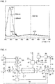
- Figure 1 shows a simplified schematic representation of a block diagram of a gas analyzer for measuring nitrogen oxides in an exhaust gas 1.
- a first light-emitting diode 2 is generated Light 3 in the wavelength range between 350 nm and 500 nm, for example with a central wavelength of 405 nm.
- a second light-emitting diode 4 generates light 5 in the wavelength range between 250 nm and 265 nm, for example with a central wavelength of 254 nm.
- Both LEDs 2, 4 are from controlled by a control device 6 which, in the exemplary embodiment shown here, contains a multiplexer 7 in order to switch the light-emitting diodes 2, 4 on and off alternately.
- the light 3, 5 emitted by the light-emitting diodes 2, 4 is shaped with the aid of collimator lenses 8, 9 into parallel light bundles (hereinafter referred to as light beams) and fed to a beam splitter 10, preferably a so-called polka-dot beam splitter, which has a constant Has reflection / transmission ratio over a large spectral range.
- the beam splitter 10 splits the light 3, 5 from the light-emitting diodes 2, 4 into a partial beam through a measuring chamber 11 to a detector 12 and a further partial beam to a reference detector 13.
- the respective partial beams are focused with the aid of lenses 14, 15 on the detectors 12, 13, which are photodiodes here.
- the exhaust gas 1 is first passed through an oxidation device 17 via an optional controllable three-way mixing valve 16 before it reaches the measuring chamber 11.
- the exhaust gas flow can be set to predetermined flow values and kept constant in a manner known per se by pressure or flow control. After flowing through the measuring chamber 11, the exhaust gas 1 is discharged from the latter.
- the oxidation device 17 has an ozone generator 18 in the form of an ultraviolet light source in a closed reaction chamber 19 through which the exhaust gas 1 flows. With its UV radiation at wavelengths less than 240 nm, the ultraviolet light source 18 generates ozone from the residual oxygen in the exhaust gas 1, with which the nitrogen monoxide contained in the exhaust gas 1 reacts in the reaction chamber 19 to form nitrogen dioxide and some higher nitrogen oxides, mainly nitrogen trioxide and nitrous oxide. However, the higher nitrogen oxides only arise if too much ozone is produced in the ozone generator 18. If, on the other hand, no or only a little excess ozone is produced, an almost complete conversion of nitrogen monoxide into nitrogen dioxide takes place.
- the controllable three-way mixing valve 16 serves to add atmospheric oxygen 20 to the exhaust gas 1 if the residual oxygen content of the exhaust gas 1 or the power of the ozone generator 18 are not sufficient to generate the amount of ozone required for the complete conversion of nitrogen monoxide into nitrogen dioxide.
- the ultraviolet light source 18 is dimmable and is supplied or controlled by an operating device 21.
- FIG 2 shows in a very simplified manner an embodiment of the oxidation device 17 with here an ultraviolet light source 18 in the form of a commercially available xenon excimer emitter 22.
- This has a cylindrical, double-walled quartz tube 23 in a known manner, which is filled with xenon in the annular space between the walls .
- Electrodes 24, 25 arranged on the inner and outer wall of the quartz tube 23 are connected to the operating device 21.
- the reaction chamber 19 is formed by an internally mirrored aluminum tube 26, in which the xenon excimer radiator 22 is arranged and through which the exhaust gas 1 flows.
- the xenon excimer emitter 22 generates UV radiation with a main wavelength of 172 nm, by means of which ozone is generated from the residual oxygen in the exhaust gas, with which the nitrogen monoxide contained in the exhaust gas 1 is converted into nitrogen dioxide. If the exhaust gas 1 has a comparatively low nitrogen monoxide concentration (for example ⁇ 5 ppm), it can be advantageous to reduce the intensity of the UV radiation emitted from the outset, which in the exemplary embodiment shown occurs because the outer electrode is 24 is formed by a wire which is wound on the quartz tube 23.
- the ultraviolet light source 18, instead of a xenon excimer emitter 22, can also have two or more such emitters in one or more parallel tubes, or at least one flow excimer lamp, as is inherently known from the already mentioned EP 0 697 374 A1 is known.
- Other lamp types such as e.g. B. mercury (Hg) low-pressure vapor lamps are used, which are operated with electronic ballast or electrodeless with high-frequency excitation (energy coupling with microwave generator).
- Hg mercury
- dielectric barrier discharge based on xenon excimers there is the advantage that it is ready for immediate use compared to other discharge lamps whose luminous gas only has to reach its operating pressure after the lamp has been ignited.
- Another advantage over mercury vapor lamps is their temperature independence.
- Figure 3 shows an example of the absorption spectra of nitrogen dioxide NO2, ozone O3 and sulfur dioxide SO2 as well as the emission spectra of the two light-emitting diodes 2, 4 represented here by the central wavelengths 405 nm and 254 nm for measuring the components nitrogen dioxide and ozone.
- the detector 3 which detects the light 3, 5 of the light-emitting diodes 2, 4, generates a detector signal 27 which, in accordance with the alternating activation of the light-emitting diodes 2, 4, contains two alternating signal components, one of which is a first signal component results from the light 3 of the first light-emitting diode 2 and a second signal component from the light of the second light-emitting diode 4.
- the reference detector 13 generates a reference signal 28 with reference signal components which result from the light 3, 5 of both light-emitting diodes 2, 4 and which alternate in succession.
- the detector signal 27 and the reference signal 28 are fed to an evaluation device 29 which contains a demultiplexer 30 for separating the different signal components.
- the synchronization of the multiplexer 7 and demultiplexer 30 takes place via a communication line 31 between the control device 6 and the evaluation device 29.
- the signals 27, 28 are determined in a computing device 32 from the first signal portion of the detector signal 27, the nitrogen dioxide concentration and from the second signal portion of the detector signal 27, the excess ozone concentration of the treated exhaust gas 1 in the measuring chamber 11.
- the two signal components of the detector signal 27 are referenced with the associated signal components of the reference signal 28, so that the concentrations determined depend on the brightness of the light-emitting diodes 2, 4 and thus, for. B. are independent of their age.
- the determined nitrogen dioxide concentration in the treated exhaust gas 1 is output as the nitrogen oxide concentration 33 of the exhaust gas 1.
- the determined excess ozone concentration 34 is supplied as an actual value to a control device 35 which controls the ozone generator 18, here the operating device 21 of the UV lamp, in order to bring the excess ozone concentration in the treated exhaust gas 1 to a predetermined target value 36 in the form of a regulate minimum residual ozone content. This ensures that only as much ozone is produced as is necessary for the conversion of nitrogen monoxide into nitrogen dioxide and that the conversion of nitrogen monoxide to nitrogen dioxide is therefore almost complete.
- atmospheric oxygen 20 can be added to the exhaust gas 1 via the three-way mixing valve 16.
- the admixture can take place manually or automatically as a function of the determined ozone concentration 34 in the treated exhaust gas 1, for example if the ozone concentration 34 falls below the target value 36 by a predetermined amount.
- the gas analyzer shown can easily be used for measuring other components of the exhaust gas 1, such as. B. carbon dioxide, carbon monoxide, sulfur, chlorine and iodine compounds are expanded.
- suitable light sources e.g. light-emitting diodes
- individual light-emitting diodes that are already present can be provided with a phosphor (phosphor) which partially converts the light generated by the light-emitting diode in question into a light with a longer wavelength.
- phosphor phosphor
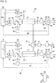
- Figure 4 shows a second embodiment of the gas analyzer according to the invention which differs from Figure 1 differs in that the two light-emitting diodes 2, 4 (and possibly further light-emitting diodes, not shown here) are arranged next to one another in an array 39.
- the light-emitting diodes 2, 4 are shown here one behind the other only for reasons of better representation. Instead of two collimator lenses for the two light-emitting diodes 2, 4, only the common collimator lens 9 is required here.
- a third light-emitting diode 40 is provided for measuring the sulfur dioxide concentration in the exhaust gas 1, which produces light 41 in the wavelength range between 250 nm and 300 nm, for example with a central wavelength of 285 nm.
- Figure 3 shows an example of the emission spectrum of the third light-emitting diode 40 represented by the central wavelength 285 nm.
- the light 41 of the third light-emitting diode 40 is formed into a parallel light bundle by means of the collimator lens 8 and by means of the beam splitter 10 together with the light 3, 5 of the first and second light-emitting diodes 2, 4 in a partial beam through the measuring chamber 11 onto the detector 12 and passed to reference detector 13 in a further partial beam.
- the detector signal 27 therefore contains a third signal component resulting from the light 41 of the third light-emitting diode 40, from which the evaluation device 29 determines the sulfur dioxide concentration 42 of the exhaust gas 1 in the measuring chamber 11.
- the LEDs 2, 4, 40 are not controlled in multiplex mode, but are modulated differently via signal generators 43, 44, 45, e.g. B. with different modulation frequencies, clock rates or pulse codes.
- the evaluation device 29 contains a demodulator 46, which is designed to demodulate or decode the signal components of the detector signal 27 and the reference signal 28 at the different modulation frequencies or clock rates in a phase-sensitive manner in order to separate the signal components for further processing and evaluation.
- the different arrangement of the light-emitting diodes 2, 4, 40 and their different control represent mutually independent measures which can accordingly be used individually or together.
- the ozone is generated exclusively from atmospheric oxygen 20 and then mixed with the exhaust gas 1 to be treated in a mixing chamber 47.
- the ozone can also be generated from the residual oxygen content of the exhaust gas 1, as shown in FIG Figure 1 is shown.
- Figure 5 shows a third embodiment of the gas analyzer according to the invention, which is also used to measure the nitrogen oxide concentration, sulfur dioxide concentration and ozone concentration in the exhaust gas 1.
- Two almost identical analyzer units 48 and 49 are used here, of which the analyzer unit 48 is shown in FIG Figure 1
- Gas analyzer shown with the first and second light emitting diodes 2, 3, the measuring chamber 11 and the oxidation device 17 for measuring the nitrogen oxide concentration and ozone concentration in the treated exhaust gas 1 corresponds.
- the second analyzer unit 49 has a third light-emitting diode 40, a fourth light-emitting diode 50 and a further measuring chamber 51 through which the untreated exhaust gas 1 flows.
- the exhaust gas 1 flows successively through the further measuring chamber 51 of the analyzer unit 49, the oxidizing device 17 and the measuring chamber 11 of the analyzer unit 48.
- the exhaust gas 1 can flow into a partial flow through the oxidizing device 17 and the measuring chamber 11 of the analyzer unit 48 and a further partial stream parallel to it can be divided by the further measuring chamber 51 of the analyzer unit 49.
- the third light-emitting diode 40 generates light 41 in the wavelength range between 250 nm and 300 nm, for example with a central wavelength of 285 nm.
- the fourth light-emitting diode 50 generates light 52 in the same wavelength range as the first light-emitting diode 2, ie between 350 nm and 500 nm, for example with a central wavelength of 405 nm.
- the third and fourth light emitting diodes 40, 50 are controlled by a control device 53 which, in the exemplary embodiment shown here, contains a multiplexer 54 in order to alternately switch the light emitting diodes 40, 50 on and off.
- the Light 41, 52 emitted by the light-emitting diodes 40, 50 is shaped into parallel light bundles with the aid of collimator lenses 55, 56 and by means of a polka-dot beam splitter 57 into a partial beam through the further measuring chamber 51 onto a (further) detector 58 and one another sub-beam divided into a (further) reference detector 59.
- the respective partial beams are focused on the detectors 58, 59 with the aid of lenses 60, 61.
- the further detector 58 generates a further detector signal 62 with a third signal component resulting from the light 41 of the third light-emitting diode 40 and a fourth signal component resulting from the light 52 of the fourth light-emitting diode 50.
- the further reference detector 59 generates a further reference signal 63 with third and fourth reference signal components resulting from the light 40, 52 of the third and fourth light emitting diodes 40, 51.
- the further detector signal 62 and reference signal 63 are fed to a further evaluation device 64, which contains a demultiplexer 65 for separating the different signal components.
- the multiplexer 54 and demultiplexer 65 are synchronized via a communication line 66 between the control device 53 and the evaluation device 64.
- a computing device 67 the sulfur dioxide concentration 42 is converted from the third signal component of the detector signal 62 and the nitrogen dioxide concentration from the fourth signal component of the detector signal 62.
- the two signal components of the detector signal 62 are referenced with the associated signal components of the reference signal 63.
- the first analyzer unit 48 thus determines the nitrogen dioxide concentration of the UV-treated exhaust gas, which corresponds to the nitrogen oxide concentration 33 when nitrogen monoxide is converted almost completely to nitrogen dioxide.
- the second analyzer unit 49 determines the nitrogen dioxide concentration 68 of the untreated exhaust gas 1, so that the nitrogen monoxide concentration 70 of the exhaust gas 1 can be determined and output in a device 69 by forming the difference between the nitrogen dioxide concentrations 33, 68 determined by the two evaluation devices 29, 64.
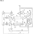
- Figure 6 finally shows a fourth exemplary embodiment of the gas analyzer according to the invention in which the first, second and third light-emitting diodes 2, 4, 40, the measuring chamber 11 through which the UV-treated exhaust gas 1 flows and the further measuring chamber 51 through which the untreated exhaust gas 1 flows are structurally in an analyzer. Unit are summarized. The example shown represents an extension of the in Figure 4 Embodiment shown around the further measuring chamber 51.
- a beam splitter arrangement 72 consisting here of the beam splitter 10 and a further beam splitter 71, a first part of the light 3 of the first light-emitting diode 2 is passed through the measuring chamber 11 through which the treated exhaust gas 1 flows and onto the detector 12 and a second part branches off to the further detector 58 through the further measurement chamber 51 through which the untreated exhaust gas 1 flows.
- Part of the light 5 of the second light-emitting diode 4 reaches the detector 12 through the measuring chamber 11 through which the treated exhaust gas 1 flows and part of the light 41 of the third light-emitting diode 40 passes through the further measuring chamber 51 through which the untreated exhaust gas 1 flows A remaining part of the light 3, 5, 41 of all light-emitting diodes 2, 4, 40 is directed to the reference detector 13.
- the light emitting diodes 2, 4, 40 are modulated differently by the signal generators 43, 44, 45 of the control device 6.
- the evaluation device is designed to process the further detector signal 62 of the further detector 58 in addition to the detector signal 29 of the detector 12 and contains a demodulator 46 which demodulates the signal components of the detector signals 27, 62 and the reference signal 28 and for further processing and evaluation separates in the computing device 32.
- the computing device 32 determines the nitrogen dioxide concentration of the treated exhaust gas 1 and thus the nitrogen oxide concentration 33 from the first signal portion of the detector signal 27 resulting from the light 3 of the first light-emitting diode 2.
- the ozone concentration 34 in the treated exhaust gas 1 is determined.
- the sulfur dioxide concentration 42 of the exhaust gas 1 is determined from the third signal component in the further detector signal 62 resulting from the light 41 of the third light-emitting diode 40.
- the nitrogen dioxide concentration 68 in the untreated exhaust gas 1 is determined from the fourth signal component of the detector signal 27 resulting from the light 3 of the first light-emitting diode 2 in the further detector signal 62.
- the nitrogen monoxide concentration 70 of the exhaust gas 1 is determined from the difference between the nitrogen dioxide concentrations 33, 68 measured in the treated and the untreated exhaust gas 1.
Landscapes
- Chemical & Material Sciences (AREA)
- Physics & Mathematics (AREA)
- Health & Medical Sciences (AREA)
- Life Sciences & Earth Sciences (AREA)
- Engineering & Computer Science (AREA)
- Pathology (AREA)
- Biochemistry (AREA)
- General Health & Medical Sciences (AREA)
- General Physics & Mathematics (AREA)
- Immunology (AREA)
- Analytical Chemistry (AREA)
- Spectroscopy & Molecular Physics (AREA)
- Combustion & Propulsion (AREA)
- Medicinal Chemistry (AREA)
- Food Science & Technology (AREA)
- Chemical Kinetics & Catalysis (AREA)
- Mechanical Engineering (AREA)
- General Engineering & Computer Science (AREA)
- Molecular Biology (AREA)
- Toxicology (AREA)
- Investigating Or Analysing Materials By Optical Means (AREA)
- Investigating Or Analysing Materials By The Use Of Chemical Reactions (AREA)
Claims (14)
- Analyseur de gaz pour la mesure d'oxydes d'azote dans un gaz (1) d'échappement, comprenant- un dispositif (17) d'oxydation, qui a un générateur (18) d'ozone pour la production d'ozone à partir d'oxygène et qui est constitué pour le traitement du gaz (1) d'échappement par l'ozone afin de transformer le monoxyde d'azote contenu dans le gaz (1) d'échappement en dioxyde d'azote,- une première diode (2) électroluminescente rayonnant à une longueur d'onde centrale comprise entre 350 nm et 500 nm,- une deuxième diode (4) électroluminescente rayonnant à une longueur d'onde centrale comprise entre 250 nm et 265 nm,- une chambre (11) de mesure dans laquelle passent le gaz (1) d'échappement à traiter et la lumière (3) de la première diode (2) électroluminescente et la lumière (5) de la deuxième diode (4) électroluminescente,- un détecteur (12) détectant la lumière (3) de la première diode (2) électroluminescente et la lumière (5) de la deuxième diode (4) électroluminescente après passage dans la chambre (11) de mesure et produisant un signal (27) de détecteur ayant une première partie de signal provenant de la lumière (3) de la première diode (2) électroluminescente et une deuxième partie de signal provenant de la lumière (5) de la deuxième diode (4) électroluminescente,- un dispositif (29) d'exploitation, qui, à partir de la première partie du signal, détermine la concentration en dioxyde d'azote du gaz (1) d'échappement traité dans la chambre (11) de mesure et la donne comme la concentration (33) en oxyde d'azote du gaz (1) d'échappement et qui, à partir de la deuxième partie de signal, détermine la concentration en ozone du gaz (1) d'échappement dans la chambre (11) de mesure,caractérisé- en ce que le générateur (18) d'ozone est réglable, et- en ce qu'il y a un dispositif (35) de réglage, qui commande le générateur (18) d'ozone et qui reçoit la concentration en ozone déterminée comme valeur (34) réelle pour la régler à une valeur (36) de consigne donnée à l'avance.
- Analyseur de gaz suivant la revendication 1, caractérisé en ce qu'il est prévu un diviseur (10) de faisceau, qui dérive une partie de la lumière (3, 5) des première et deuxième diodes (2, 4) électroluminescentes sur un détecteur (13) de référence, en ce que le détecteur (13) de référence produit un signal (28) de référence ayant des première et deuxième parties de signal de référence provenant de la lumière (3, 5) des première et deuxième diodes (2, 4) électroluminescentes et en ce que le dispositif (29) d'exploitation établit un rapport entre les parties du signal (27) du détecteur et les parties de signal de référence associées.
- Analyseur de gaz suivant la revendication 1 ou 2, caractérisé en ce que le générateur (18) d'ozone a une source de lumière ultraviolette.
- Analyseur de gaz suivant la revendication 3, caractérisé en ce que la source (18) de lumière ultraviolette a au moins un émetteur (22) à excimère de xénon.
- Analyseur de gaz suivant la revendication 3 ou 4, caractérisé en ce que la source (18) de lumière ultraviolette est disposée dans une chambre (19) de réaction fermée et dans laquelle passe le gaz (1) d'échappement et est constituée pour produire l'ozone à partir de la teneur résiduelle en oxygène du gaz (1) d'échappement.
- Analyseur de gaz suivant l'une des revendications précédentes, caractérisé- en ce qu'il y a une troisième diode (40) électroluminescente rayonnant à une longueur d'onde centrale comprise entre 250 nm et 300 nm, dont la lumière (41) passe également dans la chambre (11) de mesure et est détectée ensuite par le détecteur (12), de sorte que le signal (27) du détecteur contient une troisième partie de signal provenant de la lumière (41) de la troisième diode (40) électroluminescente, et- en ce que le dispositif (29) d'exploitation détermine, à partir de la troisième partie de signal, la concentration en dioxyde de soufre du gaz (1) d'échappement dans la chambre (11) de mesure.
- Analyseur de gaz suivant la revendication 6 en liaison avec la revendication 2, caractérisé en ce que le diviseur (10) de faisceau dérive une partie de la lumière (41) de la troisième diode (40) électroluminescente, de manière à ce que le signal (28) de référence contienne une troisième partie de signal de référence provenant de la lumière (41) de la troisième diode (40) électroluminescente, et en ce que le dispositif (29) d'exploitation établit un rapport entre la troisième partie du signal (27) du détecteur et la troisième partie de signal de référence.
- Analyseur de gaz suivant l'une des revendications 1 à 5, comprenant- une troisième diode (40) électroluminescente rayonnant à une longueur d'onde centrale comprise entre 250 nm et 300 nm,- une quatrième diode (50) électroluminescente rayonnant à une longueur d'onde centrale comprise entre 350 nm et 500 nm, de préférence à la même longueur d'onde centrale que la première diode (2) électroluminescente,- une autre chambre (51) de mesure dans laquelle passent le gaz (1) d'échappement non-traité et la lumière (41, 52) des troisième et quatrième diodes (40, 50) électroluminescentes,- un autre détecteur (58), qui détecte la lumière (41, 52) des troisième et quatrième diodes (40, 50) électroluminescentes, après traversée de l'autre chambre (51) de mesure, et qui produit un autre signal (62) de détecteur ayant une troisième partie de signal provenant de la lumière (41) de la troisième diode (40) électroluminescente et une quatrième partie de signal provenant de la lumière (52) de la quatrième diode (50) électroluminescente,- un autre dispositif (64) d'exploitation, qui, à partir de la troisième partie de signal, détermine la concentration en dioxyde de soufre et, à partir de la quatrième partie de signal, détermine la concentration (68) en dioxyde d'azote du gaz (1) d'échappement non-traité dans l'autre chambre (51) de mesure, et- un dispositif (69), qui donne la différence entre les concentrations (33, 68) en dioxyde d'azote déterminées par les deux dispositifs (29, 64) d'exploitation comme concentration (70) en monoxyde d'azote du gaz (1) d'échappement (figure 5).
- Analyseur de gaz suivant la revendication 8, caractérisé en ce qu'il est prévu un autre diviseur (57) de faisceau, qui dérive une partie de la lumière (41, 52) des troisième et quatrième diodes (40, 50) électroluminescentes sur un autre détecteur (59) de référence, en ce que l'autre détecteur (59) de référence produit un autre signal (63) de référence ayant des troisième et quatrième parties de signal de référence provenant de la lumière des troisième et quatrième diodes (40, 50) électroluminescentes et en ce que l'autre dispositif (64) d'exploitation établit un rapport entre les troisième et quatrième parties de l'autre signal (62) de détecteur et les parties de signal de référence associées.
- Analyseur de gaz suivant l'une des revendications 1 à 5, comprenant- une troisième diode (40) électroluminescente rayonnant à une longueur d'onde centrale comprise entre 250 nm et 300 nm,- une autre chambre (51) de mesure dans laquelle passent le gaz (1) d'échappement non-traité et la lumière (41) de la troisième diode (40) électroluminescente,- un agencement (72) de diviseur de faisceau, qui fait passer une partie de la lumière (3) de la première diode (2) électroluminescente dans l'autre chambre (51) de mesure,- un autre détecteur (58), qui détecte la lumière (3, 41) des première et troisième diodes (2, 40) électroluminescentes, après passage dans l'autre chambre (51) de mesure, et qui produit un autre signal (62) de détecteur ayant une troisième partie de signal provenant de la lumière (41) de la troisième diode (40) électroluminescente et une quatrième partie de signal provenant de la lumière (3) de la première diode (2) électroluminescente, et- en ce que le dispositif (29) d'exploitation détermine, en outre, à partir de la troisième partie de signal, la concentration en dioxyde de soufre et, à partir de la quatrième partie de signal, la concentration en dioxyde d'azote du gaz (1) d'échappement non-traité dans l'autre chambre (51) de mesure, et donne la différence des concentrations (33, 68) de dioxyde d'azote déterminées à partir des première et quatrième parties de signal comme concentration (70) en monoxyde d'azote du gaz (1) d'échappement (figure 6).
- Analyseur de gaz suivant la revendication 10, caractérisé en ce que l'agencement (72) de diviseur de faisceau est constitué pour dériver une partie de la lumière (3, 5, 41) des première, deuxième et troisième diodes (2,4, 40) électroluminescentes sur un détecteur (13) de référence, qui produit un signal (28) de référence ayant des parties de signal de référence provenant de la lumière (3, 5, 41) des diodes (2, 4, 40) électroluminescentes et en ce que le dispositif (29) d'exploitation établit un rapport entre les parties des signaux (27, 62) du détecteur et les parties de signal de référence associées.
- Procédé de mesure d'oxydes d'azote dans un gaz (1) d'échappement, dans lequel- on produit de l'ozone à partir de l'oxygène au moyen d'un générateur (18) d'ozone,- on traite le gaz (1) d'échappement par l'ozone produite, afin de transformer le monoxyde d'azote contenu dans le gaz (1) d'échappement en du dioxyde d'azote, et- on mesure la concentration en dioxyde d'azote du gaz (1) d'échappement traité, photométriquement en utilisant une première diode (2) électroluminescente rayonnant à une longueur d'onde centrale comprise entre 350 nm et 500 nm et on la donne comme la concentration (33) en oxyde d'azote du gaz (1) d'échappement, et- on mesure la concentration en ozone du gaz (1) d'échappement traité, photométriquement en utilisant une deuxième diode (4) électroluminescente rayonnant à une longueur d'onde centrale comprise entre 250 nm et 265 nm,- la lumière de la première diode (2) électroluminescente et de la deuxième diode (4) électroluminescente passant dans une chambre (11) de mesure, dans laquelle passe le gaz (1) d'échappement traité,caractérisé- en ce que le générateur (18) d'ozone est réglable et est commandé par un dispositif (35) de réglage, et- en ce que le dispositif (35) de réglage reçoit la concentration en ozone mesurée comme valeur réelle et la règle à une valeur de consigne donnée à l'avance.
- Procédé suivant la revendication 12, caractérisé en ce que l'on mesure la concentration en dioxyde de soufre du gaz (1) d'échappement traité ou non-traité, photométriquement en utilisant une troisième diode (40) électroluminescente rayonnant à une longueur d'onde centrale comprise entre 250 nm et 300 nm.
- Procédé suivant la revendication 12 ou 13, caractérisé en ce que l'on mesure la concentration en dioxyde d'azote du gaz (1) d'échappement non-traité, photométriquement en utilisant une quatrième diode (50) électroluminescente rayonnant à une longueur d'onde centrale comprise entre 350 nm et 500 nm, de préférence à la même longueur d'onde centrale que la première diode (2) électroluminescente, et on détermine, à partir de la différence des concentrations en dioxyde d'azote déterminées dans le gaz (1) d'échappement traité et dans le gaz (1) d'échappement non-traité, la concentration en monoxyde d'azote du gaz (1) d'échappement.
Priority Applications (3)
| Application Number | Priority Date | Filing Date | Title |
|---|---|---|---|
| EP18167338.5A EP3553499B1 (fr) | 2018-04-13 | 2018-04-13 | Analyseur de gaz et procédé de mesure des oxydes d'azote dans un gaz d'échappement |
| US16/383,034 US11226322B2 (en) | 2018-04-13 | 2019-04-12 | Optical gas analyzer and method for measuring nitrogen oxides in an exhaust gas |
| CN201910297199.1A CN110376152B (zh) | 2018-04-13 | 2019-04-12 | 用于测量废气中的氮氧化物的气体分析器和方法 |
Applications Claiming Priority (1)
| Application Number | Priority Date | Filing Date | Title |
|---|---|---|---|
| EP18167338.5A EP3553499B1 (fr) | 2018-04-13 | 2018-04-13 | Analyseur de gaz et procédé de mesure des oxydes d'azote dans un gaz d'échappement |
Publications (2)
| Publication Number | Publication Date |
|---|---|
| EP3553499A1 EP3553499A1 (fr) | 2019-10-16 |
| EP3553499B1 true EP3553499B1 (fr) | 2020-03-25 |
Family
ID=62002019
Family Applications (1)
| Application Number | Title | Priority Date | Filing Date |
|---|---|---|---|
| EP18167338.5A Active EP3553499B1 (fr) | 2018-04-13 | 2018-04-13 | Analyseur de gaz et procédé de mesure des oxydes d'azote dans un gaz d'échappement |
Country Status (3)
| Country | Link |
|---|---|
| US (1) | US11226322B2 (fr) |
| EP (1) | EP3553499B1 (fr) |
| CN (1) | CN110376152B (fr) |
Cited By (1)
| Publication number | Priority date | Publication date | Assignee | Title |
|---|---|---|---|---|
| DE202021104857U1 (de) | 2021-09-09 | 2022-12-20 | Sick Ag | Analysevorrichtung |
Families Citing this family (6)
| Publication number | Priority date | Publication date | Assignee | Title |
|---|---|---|---|---|
| DE102017213196A1 (de) * | 2017-07-31 | 2019-01-31 | Siemens Aktiengesellschaft | Gasanalysator zur Messung von Stickoxiden und Schwefeldioxid in Abgasen |
| DE102017213980A1 (de) * | 2017-08-10 | 2019-02-14 | Siemens Aktiengesellschaft | Gasanalysator zur Messung von Stickoxiden und mindestens einer weiteren Komponente eines Abgases |
| CN114636673A (zh) * | 2020-12-16 | 2022-06-17 | 北京博瑞赛科技有限责任公司 | 高浓度氮氧化物检测方法及检测系统 |
| EP4402456A1 (fr) | 2021-09-15 | 2024-07-24 | Thermo Environmental Instruments LLC | Analyseur de gaz |
| CN114345093B (zh) * | 2022-01-24 | 2022-10-11 | 广州科威环保工程有限公司 | 一种除臭效果好的泵站等离子除臭装置 |
| CN118169335A (zh) * | 2024-03-22 | 2024-06-11 | 山西泰瑞祥科技有限公司 | 一种氮氧监测系统 |
Family Cites Families (33)
| Publication number | Priority date | Publication date | Assignee | Title |
|---|---|---|---|---|
| US3652227A (en) * | 1969-12-15 | 1972-03-28 | Beckman Instruments Inc | Nitric oxide analysis |
| US3718429A (en) * | 1971-03-15 | 1973-02-27 | Du Pont | No-no2 analyzer |
| JPS5610582B2 (fr) * | 1972-02-04 | 1981-03-09 | ||
| JPS513289A (ja) * | 1974-06-26 | 1976-01-12 | Mitsubishi Heavy Ind Ltd | Chitsusosankabutsuno bunsekihoho |
| JPS52119988A (en) * | 1976-04-01 | 1977-10-07 | Isao Nishino | Measuring methode of nitrogen oxide concentration |
| US4078896A (en) * | 1977-01-21 | 1978-03-14 | International Telephone And Telegraph Corporation | Photometric analyzer |
| US4314344A (en) * | 1980-01-31 | 1982-02-02 | Dasibi Environmental Corporation | Method and apparatus for generating selected gas concentrations |
| JPS60119443A (ja) * | 1983-11-30 | 1985-06-26 | Shimadzu Corp | 光吸収式ガス分析計 |
| JPS62221422A (ja) * | 1986-03-20 | 1987-09-29 | Ishikawajima Harima Heavy Ind Co Ltd | 湿式脱硝におけるオゾン量制御方法 |
| DE4314510A1 (de) * | 1993-05-03 | 1994-11-10 | Abb Research Ltd | Verfahren zur Erzeugung von Ozon |
| EP0697374B1 (fr) | 1994-08-15 | 2000-03-22 | Sulzer Chemtech AG | Appareil pour traitement de fluides par rayonnement U.V. |
| US5739038A (en) * | 1996-07-26 | 1998-04-14 | Anarad, Inc. | Spectrometer gas analyzer system |
| JPH11211663A (ja) * | 1998-01-29 | 1999-08-06 | Shimadzu Corp | 化学発光式窒素酸化物計 |
| WO1999053297A1 (fr) * | 1998-04-14 | 1999-10-21 | Instrumentarium Corporation | Ensemble de detection et procede de mesure du dioxyde d'azote |
| DE10036948A1 (de) * | 2000-07-28 | 2002-02-21 | Abb Patent Gmbh | Verfahren zur MO¶x¶-Messung |
| EP1889035A2 (fr) | 2005-05-16 | 2008-02-20 | Dow Gloval Technologies Inc. | Commande d'excedant d'air de bruleurs de four de craqueur |
| WO2008085411A2 (fr) | 2006-12-27 | 2008-07-17 | Valencell, Inc. | Dispositifs optiques à longueurs d'onde multiples et leurs procédés d'utilisation |
| EP2118638B2 (fr) | 2007-02-26 | 2017-08-16 | Yokogawa Corporation of America | Analyse de gaz de combustion |
| US8500442B2 (en) | 2007-02-26 | 2013-08-06 | Yokogawa Corp. Of America | Combustion gas analysis |
| JP2010048582A (ja) | 2008-08-19 | 2010-03-04 | Mitsubishi Chemical Analytech Co Ltd | 硫黄の分析方法および分析装置 |
| GB0816445D0 (en) | 2008-09-09 | 2008-10-15 | Harley Phillip E | Instrument for determining ozone concentration |
| EP2256485A1 (fr) | 2009-05-29 | 2010-12-01 | Kjærulf Pedersen A/S | Système pour contrôler et détecter la concentration en éthylène dans une atmosphère contrôlée et un environnement de transport |
| JP2012026331A (ja) * | 2010-07-22 | 2012-02-09 | Toyota Industries Corp | 排ガス後処理システム |
| US20120170043A1 (en) * | 2010-09-09 | 2012-07-05 | Adelphi University | Sensitive and Compact Sensor Employing a Visible Diode Laser and A High Finesse Optical Cavity for Trace Gas Detection (NO2) |
| GB201209738D0 (en) * | 2012-05-31 | 2012-07-18 | Ge Healthcare Bio Sciences Ab | Methods and apparatus for measuring the concentration of a substance in a solution |
| JP6024856B2 (ja) | 2014-05-27 | 2016-11-16 | 富士電機株式会社 | ガス分析計 |
| DE102015000423A1 (de) | 2015-01-14 | 2016-07-14 | Universität Heidelberg | Ozongenerator, NO-zu-NO₂-Konverter, Verfahren zum Konvertieren von NO zu NO₂ und Verwendung |
| CN105424631B (zh) * | 2015-12-25 | 2018-12-07 | 中国科学院合肥物质科学研究院 | 一种基于紫外可见波段吸收光谱的超高灵敏度氮氧化物测量系统 |
| DE202017001743U1 (de) | 2017-03-31 | 2017-05-08 | Siemens Aktiengesellschaft | Gasanalysator |
| CN107158910B (zh) | 2017-06-28 | 2023-11-21 | 青岛国林科技集团股份有限公司 | 一种烟气脱硝用臭氧反应装置 |
| DE102017213196A1 (de) * | 2017-07-31 | 2019-01-31 | Siemens Aktiengesellschaft | Gasanalysator zur Messung von Stickoxiden und Schwefeldioxid in Abgasen |
| DE102017213980A1 (de) * | 2017-08-10 | 2019-02-14 | Siemens Aktiengesellschaft | Gasanalysator zur Messung von Stickoxiden und mindestens einer weiteren Komponente eines Abgases |
| CN107764774B (zh) | 2017-11-06 | 2023-05-23 | 浙江大学 | 一种同时测量烟气脱硝中一氧化氮和氨气的装置及方法 |
-
2018
- 2018-04-13 EP EP18167338.5A patent/EP3553499B1/fr active Active
-
2019
- 2019-04-12 CN CN201910297199.1A patent/CN110376152B/zh active Active
- 2019-04-12 US US16/383,034 patent/US11226322B2/en active Active
Non-Patent Citations (1)
| Title |
|---|
| None * |
Cited By (1)
| Publication number | Priority date | Publication date | Assignee | Title |
|---|---|---|---|---|
| DE202021104857U1 (de) | 2021-09-09 | 2022-12-20 | Sick Ag | Analysevorrichtung |
Also Published As
| Publication number | Publication date |
|---|---|
| US20190317067A1 (en) | 2019-10-17 |
| US11226322B2 (en) | 2022-01-18 |
| CN110376152A (zh) | 2019-10-25 |
| CN110376152B (zh) | 2023-01-31 |
| EP3553499A1 (fr) | 2019-10-16 |
Similar Documents
| Publication | Publication Date | Title |
|---|---|---|
| EP3553499B1 (fr) | Analyseur de gaz et procédé de mesure des oxydes d'azote dans un gaz d'échappement | |
| EP3662261B1 (fr) | Analyseur de gaz pour mesurer les oxydes d'azote et le dioxyde de soufre dans des gaz d'échappement | |
| EP3665477B1 (fr) | Analyseur de gaz pour mesurer les oxydes d'azote et au moins un autre constituant d'un gaz d'échappement | |
| DE2136968C3 (de) | Brandmeldeanlagen | |
| US20100118301A1 (en) | System for analyzing a sample or a sample component and method for making and using same | |
| WO2000073768A2 (fr) | Dispositif de capteur de gaz | |
| EP2382460A1 (fr) | Procédé et dispositif de détection de gaz ionisables | |
| DE2806208C3 (de) | Verfahren und Vorrichtung zum Nachweis von Schwefeldioxyd in einer Gasprobe | |
| EP2510572B1 (fr) | Procédé de contrôle et/ou de régulation de piles à combustible | |
| DE102016108267B4 (de) | Vorrichtung und Verfahren zum Ermitteln einer Konzentration von wenigstens einer Gaskomponente eines Gasgemischs | |
| DE19505104A1 (de) | Verfahren und Anordnung zur Bestimmung der Reinheit und/oder des Drucks von Gasen für elektrische Lampen | |
| DE2546565C3 (de) | Verfahren und Vorrichtung zur Bestimmung der Konzentration von Schwefeldioxid | |
| DE2246365C3 (de) | Verfahren und Vorrichtung zur Bestimmung der Stickoxidkonzentration in einem Gasgemisch | |
| WO1996018096A1 (fr) | Detection quantitative d'especes chimiques | |
| DE102005049522B3 (de) | Gassensoranordnung | |
| DE202021104857U1 (de) | Analysevorrichtung | |
| WO2012152621A1 (fr) | Procédé et système pour la détection d'un premier gaz dans un mélange gazeux comprenant au moins un autre gaz | |
| WO2011161137A1 (fr) | Analyseur de gaz non dispersif | |
| RU2022239C1 (ru) | Устройство для оптико-абсорбционного анализа газовой смеси | |
| DE102004035916B4 (de) | Verfahren zur isotopenselektiven Bestimmung von Stickstoffmonoxid-Konzentrationen | |
| DD237772A3 (de) | Messeinrichtung zur bestimmung von schwefeldioxid, stickstoffdioxid und des rauchanteils in gasgemischen | |
| DES0026719MA (fr) |
Legal Events
| Date | Code | Title | Description |
|---|---|---|---|
| PUAI | Public reference made under article 153(3) epc to a published international application that has entered the european phase |
Free format text: ORIGINAL CODE: 0009012 |
|
| STAA | Information on the status of an ep patent application or granted ep patent |
Free format text: STATUS: REQUEST FOR EXAMINATION WAS MADE |
|
| 17P | Request for examination filed |
Effective date: 20180705 |
|
| AK | Designated contracting states |
Kind code of ref document: A1 Designated state(s): AL AT BE BG CH CY CZ DE DK EE ES FI FR GB GR HR HU IE IS IT LI LT LU LV MC MK MT NL NO PL PT RO RS SE SI SK SM TR |
|
| AX | Request for extension of the european patent |
Extension state: BA ME |
|
| GRAP | Despatch of communication of intention to grant a patent |
Free format text: ORIGINAL CODE: EPIDOSNIGR1 |
|
| STAA | Information on the status of an ep patent application or granted ep patent |
Free format text: STATUS: GRANT OF PATENT IS INTENDED |
|
| RIC1 | Information provided on ipc code assigned before grant |
Ipc: G01N 33/00 20060101ALI20191108BHEP Ipc: F01N 11/00 20060101ALI20191108BHEP Ipc: B01D 53/00 20060101ALI20191108BHEP Ipc: F01N 3/00 20060101ALI20191108BHEP Ipc: B01D 53/30 20060101ALN20191108BHEP Ipc: G01N 21/33 20060101AFI20191108BHEP Ipc: G01N 31/00 20060101ALI20191108BHEP Ipc: B01D 53/56 20060101ALN20191108BHEP |
|
| INTG | Intention to grant announced |
Effective date: 20191218 |
|
| RIN1 | Information on inventor provided before grant (corrected) |
Inventor name: HEFFELS, CAMIEL Inventor name: ROSSFELD, DANIEL |
|
| GRAS | Grant fee paid |
Free format text: ORIGINAL CODE: EPIDOSNIGR3 |
|
| GRAA | (expected) grant |
Free format text: ORIGINAL CODE: 0009210 |
|
| STAA | Information on the status of an ep patent application or granted ep patent |
Free format text: STATUS: THE PATENT HAS BEEN GRANTED |
|
| AK | Designated contracting states |
Kind code of ref document: B1 Designated state(s): AL AT BE BG CH CY CZ DE DK EE ES FI FR GB GR HR HU IE IS IT LI LT LU LV MC MK MT NL NO PL PT RO RS SE SI SK SM TR |
|
| REG | Reference to a national code |
Ref country code: GB Ref legal event code: FG4D Free format text: NOT ENGLISH |
|
| REG | Reference to a national code |
Ref country code: AT Ref legal event code: REF Ref document number: 1249112 Country of ref document: AT Kind code of ref document: T Effective date: 20200415 Ref country code: IE Ref legal event code: FG4D Free format text: LANGUAGE OF EP DOCUMENT: GERMAN |
|
| REG | Reference to a national code |
Ref country code: DE Ref legal event code: R096 Ref document number: 502018001004 Country of ref document: DE |
|
| REG | Reference to a national code |
Ref country code: NL Ref legal event code: FP |
|
| PG25 | Lapsed in a contracting state [announced via postgrant information from national office to epo] |
Ref country code: NO Free format text: LAPSE BECAUSE OF FAILURE TO SUBMIT A TRANSLATION OF THE DESCRIPTION OR TO PAY THE FEE WITHIN THE PRESCRIBED TIME-LIMIT Effective date: 20200625 Ref country code: FI Free format text: LAPSE BECAUSE OF FAILURE TO SUBMIT A TRANSLATION OF THE DESCRIPTION OR TO PAY THE FEE WITHIN THE PRESCRIBED TIME-LIMIT Effective date: 20200325 Ref country code: RS Free format text: LAPSE BECAUSE OF FAILURE TO SUBMIT A TRANSLATION OF THE DESCRIPTION OR TO PAY THE FEE WITHIN THE PRESCRIBED TIME-LIMIT Effective date: 20200325 |
|
| PG25 | Lapsed in a contracting state [announced via postgrant information from national office to epo] |
Ref country code: HR Free format text: LAPSE BECAUSE OF FAILURE TO SUBMIT A TRANSLATION OF THE DESCRIPTION OR TO PAY THE FEE WITHIN THE PRESCRIBED TIME-LIMIT Effective date: 20200325 Ref country code: LV Free format text: LAPSE BECAUSE OF FAILURE TO SUBMIT A TRANSLATION OF THE DESCRIPTION OR TO PAY THE FEE WITHIN THE PRESCRIBED TIME-LIMIT Effective date: 20200325 Ref country code: SE Free format text: LAPSE BECAUSE OF FAILURE TO SUBMIT A TRANSLATION OF THE DESCRIPTION OR TO PAY THE FEE WITHIN THE PRESCRIBED TIME-LIMIT Effective date: 20200325 Ref country code: GR Free format text: LAPSE BECAUSE OF FAILURE TO SUBMIT A TRANSLATION OF THE DESCRIPTION OR TO PAY THE FEE WITHIN THE PRESCRIBED TIME-LIMIT Effective date: 20200626 Ref country code: BG Free format text: LAPSE BECAUSE OF FAILURE TO SUBMIT A TRANSLATION OF THE DESCRIPTION OR TO PAY THE FEE WITHIN THE PRESCRIBED TIME-LIMIT Effective date: 20200625 |
|
| REG | Reference to a national code |
Ref country code: LT Ref legal event code: MG4D |
|
| PG25 | Lapsed in a contracting state [announced via postgrant information from national office to epo] |
Ref country code: IS Free format text: LAPSE BECAUSE OF FAILURE TO SUBMIT A TRANSLATION OF THE DESCRIPTION OR TO PAY THE FEE WITHIN THE PRESCRIBED TIME-LIMIT Effective date: 20200725 Ref country code: LT Free format text: LAPSE BECAUSE OF FAILURE TO SUBMIT A TRANSLATION OF THE DESCRIPTION OR TO PAY THE FEE WITHIN THE PRESCRIBED TIME-LIMIT Effective date: 20200325 Ref country code: CZ Free format text: LAPSE BECAUSE OF FAILURE TO SUBMIT A TRANSLATION OF THE DESCRIPTION OR TO PAY THE FEE WITHIN THE PRESCRIBED TIME-LIMIT Effective date: 20200325 Ref country code: RO Free format text: LAPSE BECAUSE OF FAILURE TO SUBMIT A TRANSLATION OF THE DESCRIPTION OR TO PAY THE FEE WITHIN THE PRESCRIBED TIME-LIMIT Effective date: 20200325 Ref country code: PT Free format text: LAPSE BECAUSE OF FAILURE TO SUBMIT A TRANSLATION OF THE DESCRIPTION OR TO PAY THE FEE WITHIN THE PRESCRIBED TIME-LIMIT Effective date: 20200818 Ref country code: EE Free format text: LAPSE BECAUSE OF FAILURE TO SUBMIT A TRANSLATION OF THE DESCRIPTION OR TO PAY THE FEE WITHIN THE PRESCRIBED TIME-LIMIT Effective date: 20200325 Ref country code: SM Free format text: LAPSE BECAUSE OF FAILURE TO SUBMIT A TRANSLATION OF THE DESCRIPTION OR TO PAY THE FEE WITHIN THE PRESCRIBED TIME-LIMIT Effective date: 20200325 Ref country code: SK Free format text: LAPSE BECAUSE OF FAILURE TO SUBMIT A TRANSLATION OF THE DESCRIPTION OR TO PAY THE FEE WITHIN THE PRESCRIBED TIME-LIMIT Effective date: 20200325 |
|
| PG25 | Lapsed in a contracting state [announced via postgrant information from national office to epo] |
Ref country code: MC Free format text: LAPSE BECAUSE OF FAILURE TO SUBMIT A TRANSLATION OF THE DESCRIPTION OR TO PAY THE FEE WITHIN THE PRESCRIBED TIME-LIMIT Effective date: 20200325 |
|
| REG | Reference to a national code |
Ref country code: DE Ref legal event code: R097 Ref document number: 502018001004 Country of ref document: DE |
|
| PG25 | Lapsed in a contracting state [announced via postgrant information from national office to epo] |
Ref country code: DK Free format text: LAPSE BECAUSE OF FAILURE TO SUBMIT A TRANSLATION OF THE DESCRIPTION OR TO PAY THE FEE WITHIN THE PRESCRIBED TIME-LIMIT Effective date: 20200325 Ref country code: ES Free format text: LAPSE BECAUSE OF FAILURE TO SUBMIT A TRANSLATION OF THE DESCRIPTION OR TO PAY THE FEE WITHIN THE PRESCRIBED TIME-LIMIT Effective date: 20200325 Ref country code: IT Free format text: LAPSE BECAUSE OF FAILURE TO SUBMIT A TRANSLATION OF THE DESCRIPTION OR TO PAY THE FEE WITHIN THE PRESCRIBED TIME-LIMIT Effective date: 20200325 Ref country code: LU Free format text: LAPSE BECAUSE OF NON-PAYMENT OF DUE FEES Effective date: 20200413 |
|
| PLBE | No opposition filed within time limit |
Free format text: ORIGINAL CODE: 0009261 |
|
| STAA | Information on the status of an ep patent application or granted ep patent |
Free format text: STATUS: NO OPPOSITION FILED WITHIN TIME LIMIT |
|
| PG25 | Lapsed in a contracting state [announced via postgrant information from national office to epo] |
Ref country code: PL Free format text: LAPSE BECAUSE OF FAILURE TO SUBMIT A TRANSLATION OF THE DESCRIPTION OR TO PAY THE FEE WITHIN THE PRESCRIBED TIME-LIMIT Effective date: 20200325 |
|
| REG | Reference to a national code |
Ref country code: CH Ref legal event code: NV Representative=s name: SIEMENS SCHWEIZ AG, CH |
|
| 26N | No opposition filed |
Effective date: 20210112 |
|
| PG25 | Lapsed in a contracting state [announced via postgrant information from national office to epo] |
Ref country code: IE Free format text: LAPSE BECAUSE OF NON-PAYMENT OF DUE FEES Effective date: 20200413 |
|
| PG25 | Lapsed in a contracting state [announced via postgrant information from national office to epo] |
Ref country code: LI Free format text: LAPSE BECAUSE OF NON-PAYMENT OF DUE FEES Effective date: 20210430 Ref country code: CH Free format text: LAPSE BECAUSE OF NON-PAYMENT OF DUE FEES Effective date: 20210430 |
|
| PG25 | Lapsed in a contracting state [announced via postgrant information from national office to epo] |
Ref country code: TR Free format text: LAPSE BECAUSE OF FAILURE TO SUBMIT A TRANSLATION OF THE DESCRIPTION OR TO PAY THE FEE WITHIN THE PRESCRIBED TIME-LIMIT Effective date: 20200325 Ref country code: MT Free format text: LAPSE BECAUSE OF FAILURE TO SUBMIT A TRANSLATION OF THE DESCRIPTION OR TO PAY THE FEE WITHIN THE PRESCRIBED TIME-LIMIT Effective date: 20200325 Ref country code: CY Free format text: LAPSE BECAUSE OF FAILURE TO SUBMIT A TRANSLATION OF THE DESCRIPTION OR TO PAY THE FEE WITHIN THE PRESCRIBED TIME-LIMIT Effective date: 20200325 |
|
| PG25 | Lapsed in a contracting state [announced via postgrant information from national office to epo] |
Ref country code: MK Free format text: LAPSE BECAUSE OF FAILURE TO SUBMIT A TRANSLATION OF THE DESCRIPTION OR TO PAY THE FEE WITHIN THE PRESCRIBED TIME-LIMIT Effective date: 20200325 Ref country code: AL Free format text: LAPSE BECAUSE OF FAILURE TO SUBMIT A TRANSLATION OF THE DESCRIPTION OR TO PAY THE FEE WITHIN THE PRESCRIBED TIME-LIMIT Effective date: 20200325 |
|
| PG25 | Lapsed in a contracting state [announced via postgrant information from national office to epo] |
Ref country code: SI Free format text: LAPSE BECAUSE OF FAILURE TO SUBMIT A TRANSLATION OF THE DESCRIPTION OR TO PAY THE FEE WITHIN THE PRESCRIBED TIME-LIMIT Effective date: 20200325 |
|
| PGFP | Annual fee paid to national office [announced via postgrant information from national office to epo] |
Ref country code: NL Payment date: 20240409 Year of fee payment: 7 |
|
| REG | Reference to a national code |
Ref country code: AT Ref legal event code: MM01 Ref document number: 1249112 Country of ref document: AT Kind code of ref document: T Effective date: 20230413 |
|
| PGFP | Annual fee paid to national office [announced via postgrant information from national office to epo] |
Ref country code: GB Payment date: 20240507 Year of fee payment: 7 |
|
| PG25 | Lapsed in a contracting state [announced via postgrant information from national office to epo] |
Ref country code: AT Free format text: LAPSE BECAUSE OF NON-PAYMENT OF DUE FEES Effective date: 20230413 |
|
| PG25 | Lapsed in a contracting state [announced via postgrant information from national office to epo] |
Ref country code: AT Free format text: LAPSE BECAUSE OF NON-PAYMENT OF DUE FEES Effective date: 20230413 |
|
| PGFP | Annual fee paid to national office [announced via postgrant information from national office to epo] |
Ref country code: FR Payment date: 20240415 Year of fee payment: 7 |
|
| PGFP | Annual fee paid to national office [announced via postgrant information from national office to epo] |
Ref country code: BE Payment date: 20240418 Year of fee payment: 7 |
|
| PGFP | Annual fee paid to national office [announced via postgrant information from national office to epo] |
Ref country code: DE Payment date: 20250620 Year of fee payment: 8 |
|
| REG | Reference to a national code |
Ref country code: NL Ref legal event code: MM Effective date: 20250501 |
|
| GBPC | Gb: european patent ceased through non-payment of renewal fee |
Effective date: 20250413 |
|
| REG | Reference to a national code |
Ref country code: BE Ref legal event code: MM Effective date: 20250430 |
|
| PG25 | Lapsed in a contracting state [announced via postgrant information from national office to epo] |
Ref country code: GB Free format text: LAPSE BECAUSE OF NON-PAYMENT OF DUE FEES Effective date: 20250413 |
|
| PG25 | Lapsed in a contracting state [announced via postgrant information from national office to epo] |
Ref country code: NL Free format text: LAPSE BECAUSE OF NON-PAYMENT OF DUE FEES Effective date: 20250501 Ref country code: FR Free format text: LAPSE BECAUSE OF NON-PAYMENT OF DUE FEES Effective date: 20250430 |
|
| PG25 | Lapsed in a contracting state [announced via postgrant information from national office to epo] |
Ref country code: BE Free format text: LAPSE BECAUSE OF NON-PAYMENT OF DUE FEES Effective date: 20250430 |