EP3553434A1 - Method for driving a drawer in a refrigerator - Google Patents
Method for driving a drawer in a refrigerator Download PDFInfo
- Publication number
- EP3553434A1 EP3553434A1 EP19175585.9A EP19175585A EP3553434A1 EP 3553434 A1 EP3553434 A1 EP 3553434A1 EP 19175585 A EP19175585 A EP 19175585A EP 3553434 A1 EP3553434 A1 EP 3553434A1
- Authority
- EP
- European Patent Office
- Prior art keywords
- drawer
- drive motor
- storage box
- refrigerator
- external force
- Prior art date
- Legal status (The legal status is an assumption and is not a legal conclusion. Google has not performed a legal analysis and makes no representation as to the accuracy of the status listed.)
- Granted
Links
- 238000000034 method Methods 0.000 title claims abstract description 59
- 238000001514 detection method Methods 0.000 claims description 28
- 230000007257 malfunction Effects 0.000 claims description 3
- 238000003860 storage Methods 0.000 abstract description 120
- 230000009471 action Effects 0.000 abstract description 4
- 235000013305 food Nutrition 0.000 description 14
- 238000005057 refrigeration Methods 0.000 description 10
- 230000008569 process Effects 0.000 description 5
- 238000009826 distribution Methods 0.000 description 4
- 230000000694 effects Effects 0.000 description 4
- 230000006870 function Effects 0.000 description 3
- 238000003780 insertion Methods 0.000 description 3
- 230000037431 insertion Effects 0.000 description 3
- XLYOFNOQVPJJNP-UHFFFAOYSA-N water Substances O XLYOFNOQVPJJNP-UHFFFAOYSA-N 0.000 description 3
- 238000013461 design Methods 0.000 description 2
- 238000010586 diagram Methods 0.000 description 2
- 238000007429 general method Methods 0.000 description 2
- 230000010363 phase shift Effects 0.000 description 2
- 238000003825 pressing Methods 0.000 description 2
- 238000007789 sealing Methods 0.000 description 2
- 230000035939 shock Effects 0.000 description 2
- 238000012546 transfer Methods 0.000 description 2
- 230000001133 acceleration Effects 0.000 description 1
- 230000004888 barrier function Effects 0.000 description 1
- 230000007423 decrease Effects 0.000 description 1
- 238000009434 installation Methods 0.000 description 1
- 238000009413 insulation Methods 0.000 description 1
- 239000012212 insulator Substances 0.000 description 1
- 238000004806 packaging method and process Methods 0.000 description 1
- 230000002093 peripheral effect Effects 0.000 description 1
- 230000009467 reduction Effects 0.000 description 1
- 238000005096 rolling process Methods 0.000 description 1
- 238000010079 rubber tapping Methods 0.000 description 1
- 238000004804 winding Methods 0.000 description 1
Images


Classifications
-
- F—MECHANICAL ENGINEERING; LIGHTING; HEATING; WEAPONS; BLASTING
- F25—REFRIGERATION OR COOLING; COMBINED HEATING AND REFRIGERATION SYSTEMS; HEAT PUMP SYSTEMS; MANUFACTURE OR STORAGE OF ICE; LIQUEFACTION SOLIDIFICATION OF GASES
- F25D—REFRIGERATORS; COLD ROOMS; ICE-BOXES; COOLING OR FREEZING APPARATUS NOT OTHERWISE PROVIDED FOR
- F25D29/00—Arrangement or mounting of control or safety devices
-
- F—MECHANICAL ENGINEERING; LIGHTING; HEATING; WEAPONS; BLASTING
- F25—REFRIGERATION OR COOLING; COMBINED HEATING AND REFRIGERATION SYSTEMS; HEAT PUMP SYSTEMS; MANUFACTURE OR STORAGE OF ICE; LIQUEFACTION SOLIDIFICATION OF GASES
- F25D—REFRIGERATORS; COLD ROOMS; ICE-BOXES; COOLING OR FREEZING APPARATUS NOT OTHERWISE PROVIDED FOR
- F25D25/00—Charging, supporting, and discharging the articles to be cooled
- F25D25/02—Charging, supporting, and discharging the articles to be cooled by shelves
- F25D25/024—Slidable shelves
- F25D25/025—Drawers
-
- A—HUMAN NECESSITIES
- A47—FURNITURE; DOMESTIC ARTICLES OR APPLIANCES; COFFEE MILLS; SPICE MILLS; SUCTION CLEANERS IN GENERAL
- A47B—TABLES; DESKS; OFFICE FURNITURE; CABINETS; DRAWERS; GENERAL DETAILS OF FURNITURE
- A47B88/00—Drawers for tables, cabinets or like furniture; Guides for drawers
- A47B88/40—Sliding drawers; Slides or guides therefor
- A47B88/453—Actuated drawers
- A47B88/457—Actuated drawers operated by electrically-powered actuation means
-
- A—HUMAN NECESSITIES
- A47—FURNITURE; DOMESTIC ARTICLES OR APPLIANCES; COFFEE MILLS; SPICE MILLS; SUCTION CLEANERS IN GENERAL
- A47B—TABLES; DESKS; OFFICE FURNITURE; CABINETS; DRAWERS; GENERAL DETAILS OF FURNITURE
- A47B88/00—Drawers for tables, cabinets or like furniture; Guides for drawers
- A47B88/40—Sliding drawers; Slides or guides therefor
- A47B88/453—Actuated drawers
- A47B88/46—Actuated drawers operated by mechanically-stored energy, e.g. by springs
- A47B88/463—Actuated drawers operated by mechanically-stored energy, e.g. by springs self-opening
-
- F—MECHANICAL ENGINEERING; LIGHTING; HEATING; WEAPONS; BLASTING
- F25—REFRIGERATION OR COOLING; COMBINED HEATING AND REFRIGERATION SYSTEMS; HEAT PUMP SYSTEMS; MANUFACTURE OR STORAGE OF ICE; LIQUEFACTION SOLIDIFICATION OF GASES
- F25D—REFRIGERATORS; COLD ROOMS; ICE-BOXES; COOLING OR FREEZING APPARATUS NOT OTHERWISE PROVIDED FOR
- F25D25/00—Charging, supporting, and discharging the articles to be cooled
-
- A—HUMAN NECESSITIES
- A47—FURNITURE; DOMESTIC ARTICLES OR APPLIANCES; COFFEE MILLS; SPICE MILLS; SUCTION CLEANERS IN GENERAL
- A47B—TABLES; DESKS; OFFICE FURNITURE; CABINETS; DRAWERS; GENERAL DETAILS OF FURNITURE
- A47B2210/00—General construction of drawers, guides and guide devices
- A47B2210/0002—Guide construction for drawers
- A47B2210/0064—Guide sequencing or synchronisation
- A47B2210/0078—Drawers with parallel guidance or synchronization by pinion-shaft linkages
-
- E—FIXED CONSTRUCTIONS
- E05—LOCKS; KEYS; WINDOW OR DOOR FITTINGS; SAFES
- E05Y—INDEXING SCHEME RELATING TO HINGES OR OTHER SUSPENSION DEVICES FOR DOORS, WINDOWS OR WINGS AND DEVICES FOR MOVING WINGS INTO OPEN OR CLOSED POSITION, CHECKS FOR WINGS AND WING FITTINGS NOT OTHERWISE PROVIDED FOR, CONCERNED WITH THE FUNCTIONING OF THE WING
- E05Y2201/00—Constructional elements; Accessories therefore
- E05Y2201/60—Suspension or transmission members; Accessories therefore
- E05Y2201/622—Suspension or transmission members elements
- E05Y2201/71—Toothed gearing
- E05Y2201/722—Racks
-
- F—MECHANICAL ENGINEERING; LIGHTING; HEATING; WEAPONS; BLASTING
- F25—REFRIGERATION OR COOLING; COMBINED HEATING AND REFRIGERATION SYSTEMS; HEAT PUMP SYSTEMS; MANUFACTURE OR STORAGE OF ICE; LIQUEFACTION SOLIDIFICATION OF GASES
- F25D—REFRIGERATORS; COLD ROOMS; ICE-BOXES; COOLING OR FREEZING APPARATUS NOT OTHERWISE PROVIDED FOR
- F25D25/00—Charging, supporting, and discharging the articles to be cooled
- F25D25/04—Charging, supporting, and discharging the articles to be cooled by conveyors
-
- F—MECHANICAL ENGINEERING; LIGHTING; HEATING; WEAPONS; BLASTING
- F25—REFRIGERATION OR COOLING; COMBINED HEATING AND REFRIGERATION SYSTEMS; HEAT PUMP SYSTEMS; MANUFACTURE OR STORAGE OF ICE; LIQUEFACTION SOLIDIFICATION OF GASES
- F25D—REFRIGERATORS; COLD ROOMS; ICE-BOXES; COOLING OR FREEZING APPARATUS NOT OTHERWISE PROVIDED FOR
- F25D2700/00—Means for sensing or measuring; Sensors therefor
- F25D2700/02—Sensors detecting door opening
-
- F—MECHANICAL ENGINEERING; LIGHTING; HEATING; WEAPONS; BLASTING
- F25—REFRIGERATION OR COOLING; COMBINED HEATING AND REFRIGERATION SYSTEMS; HEAT PUMP SYSTEMS; MANUFACTURE OR STORAGE OF ICE; LIQUEFACTION SOLIDIFICATION OF GASES
- F25D—REFRIGERATORS; COLD ROOMS; ICE-BOXES; COOLING OR FREEZING APPARATUS NOT OTHERWISE PROVIDED FOR
- F25D2700/00—Means for sensing or measuring; Sensors therefor
- F25D2700/04—Sensors detecting the presence of a person
Abstract
Description
- The present disclosure relates to a system and method for driving a drawer of a refrigerator.
- In general, a refrigerator is a home appliance for storing food in refrigerated or frozen states.
- Specifically, refrigerators can be divided largely into top mount, bottom freezer, and side-by-side refrigerators, depending on the respective positions of the freezer and refrigeration compartments.
- The bottom freezer configuration has the freezer compartment provided below the refrigeration compartment. A door that opens and closes the refrigeration compartment is provided to be capable of pivoting about an edge of the main body, and a door that opens and closes the freezer compartment is provided in the configuration of a storage box door that moves forward and rearward.
- Because the freezer compartment is provided below the refrigeration compartment, a user must stoop to grasp and pull the door forward in order to open the freezer compartment. Accordingly, a user must exert a greater amount of force than pulling the door from an upright standing position, causing inconvenience when opening the freezer door.
- Configurations for obviating this inconvenience through facilitating the opening of a freezer compartment door have emerged.
- One example is an automatic opening configuration that determines when a user intends to open a freezer door by sensing the user performing the movement of grasping the door handle, upon which the freezer compartment door is moved a predetermined distance forward from the front surface of the main body.
- Another proposed method involves fixedly installing a motor on the floor of the freezer compartment, and pulling the freezer compartment door out by means of driving force from the motor. In detail, a motor is fixedly installed on the floor of the freezer compartment, and a rotating member such as a gear is connected to the shaft of the motor. The undersurface of the freezer compartment shelf is brought into contact with the rotating member, so that the freezer compartment shelf moves forward and rearward according to the rotation of the rotating member.
- However, the above related art storage box-type refrigerators have the following limitations.
- First, in the case of the related art configuration that automatically withdraws a storage box, a user must still grasp and exert force to pull a handle protruding from the front surface of the storage box. However, because a sealing member such as a gasket is attached to the rear surface of the refrigerator storage box to prevent cold air leakage, an adhering member such as a magnet is provided inside the sealing member. Thus, the storage box maintains a tight seal by means of magnetic force against the refrigerator main body when closed. In this state, in order to extrude the storage box, a user must grasp and pull the storage box by exerting a force greater than the magnetic force. In addition, when the storage box is provided at the bottom of the refrigerator, a user must stoop to pull it out, potentially straining the body. That is, opening a refrigerator storage box may be physically demanding for children, the elderly, and females.
- Also, to allow the storage box to be pulled, a handle protrudes from the front surface of the storage box, thereby increasing the dimensions for the packaging of the refrigerator. When the refrigerator is installed indoors, utility of the product decreases because more installation space is required to accommodate the projection of the handle.
- Moreover, because the handle is a protrusion projecting from the front surface of the refrigerator, it presents a hazard for users who can bump into it while walking and for running children.
- The following limitations accompany the above-described refrigerator provided with the withdrawing apparatus for a storage box that pushes the storage box a distance that separates the latter from the refrigerator main body.
- First, even in a refrigerator provided with an apparatus for separating the storage box from the main body, a handle is required. That is, because the apparatus is configured to only separate the storage box from the main body when a user grasps the handle to pull the storage box forward, the handle is a necessary element, which therefore involves the limitations described above.
- Second, compared to the time it takes for a user to grasp a handle and pull the storage box forward, the time it takes for a controller to sense this movement and drive the storage box withdrawing apparatus is excessive, thus reducing utility. That is, the reacting speed of the storage box withdrawing apparatus is slow when a movement is performed to withdraw the storage box, so that a user may not perceive any improvements in convenience.
- Third, because the storage box withdrawing apparatus simply pushes the storage box a distance adequate to separate it from the refrigerator main body, there is the limitation in that a user must directly grasp the handle and pull the storage box forward thereafter. In this case, when the weight of food stored in the storage box is considerable, withdrawing the storage box is not easy.
- A refrigerator provided with a storage box withdrawing structure with a motor fixedly installed on the floor of the refrigerator main body has the following limitations.
- First, in order to apply the above structure to a refrigerator, a drive motor and gear assembly must be installed on the floor of the refrigeration compartment or the freezer compartment, and thus, the storage space within the refrigerator is reduced by the volume consumed by the motor and gear assembly.
- Second, if the drive motor and gear assembly were to be installed inward into the inner case of the refrigerator, this could induce the limitation of insulative loss in the refrigerator main body. Put differently, a refrigerator main body is formed of an outer case, an inner case, and an insulating layer provided therebetween. In such a structure, if the inner case were to be recessed to mount a motor, the insulating layer would become that much thinner, presenting the limitation of reduced insulation between the inside of the refrigerator and the indoors.
- Third, in the case where a motor and gear assembly are fixedly installed on a floor within a refrigerator, a rack that engages to a gear must be elongatedly installed from front to rear along the floor of the storage box. Here, the maximum allowable length of the rack is the overall length of the floor of the storage box. A machine room housing a compressor and a condenser is provided at the lower rear of the refrigerator. Therefore, the rear surface of a freezer compartment storage box in a bottom freezer refrigerator is sloped forward. That is, the length of the lower portion of the freezer compartment storage box is less than the length of the upper portion thereof.
- If the above storage box withdrawing structure is provided on a freezer compartment storage box of a bottom freezer refrigerator, the rack must be provided on the floor of the freezer compartment storage box. In this case, when the freezer compartment is maximally withdrawn, the upper, rear portion of the freezer compartment storage box cannot be completely extruded from the freezer compartment.
- Fourth, when a plurality of storage boxes of the refrigerator is provided one on top of another, a separate motor and gear assembly must be provided to withdraw a storage box above, thereby necessitating the need to provide separate barriers for a storage box above and a storage box below.
- Fifth, in a related art refrigerator configured with a motor fixedly installed on the floor of the refrigerator main body to withdraw a storage box, there is no accompanying function to monitor and control the speed at which the storage box is withdrawn during the process of withdrawing the storage box. In other words, in a related art refrigerator, a lead switch is installed at the front and rear of the rack installed on the floor of the refrigerator, to simply sense whether or not the storage box has been fully withdrawn or closed. Accordingly, there are limitations in that it is not possible to sense whether or not the storage box is being withdrawn at a normal speed, whether or not the withdrawing of the storage box is impeded by obstacles, and whether or not the storage box is being withdrawn at a set speed regardless of the weight of food stored therein.
- To obviate and overcome the above-described limitations, it is an object of the present disclosure to provide a storage box type refrigerator that does not require a handle structure to withdraw a storage box.
- Another object of the present disclosure is to provide a refrigerator that allows for automatic withdrawal of a storage box according to a user's wishes, by means of an improved withdrawing structure for a refrigerator storage box.
- A further object of the present disclosure is to provide a refrigerator with a structure for fixedly installing a driving unit that withdraws and inserts a storage box of a refrigerator that is improved over the related art, to minimize reductions in interior storage volume and insulating effectiveness of the refrigerator.
- A still further object of the present disclosure is to provide a system and method for driving a drawer of a refrigerator that can always withdraw and insert a storage box at a preset speed regardless of the weight of food stored therein.
- A yet further object of the present disclosure is to provide a system and method for driving a drawer, which can automatically withdraw and insert a storage box in accordance with a user's intention in a state where the storage box is withdrawn by a predetermined distance and stops.
- To achieve the above objects in accordance with embodiments of the present disclosure, there is provided a drawer driving system of a refrigerator, including: a drive motor that rotates to withdraw a drawer to a predetermined distance; and a controller for controlling an operation of the drive motor, wherein the controller controls the operation of the drive motor such that the drawer moves in a direction in which an external force is applied to the drawer in a state where the drawer stops.
- Also, in order to achieve the above objects in accordance with embodiments of the present disclosure, there is provided a method for controlling driving of a drawer for a refrigerator, including: detecting external force applied to the drawer that is in a stationary state; transferring an external force detecting signal to a controller; determining an application direction of an external force; and moving the drawer in the application direction of the external force.
- The above-configured embodiments of a withdrawing structure for a storage box of a refrigerator according to the present disclosure have the following advantages and effects.
- First, when a user performs the action of simply pressing a storage box input button, the storage box is automatically withdrawn or inserted, thus having the effect of providing children or seniors with greater convenience of use. Moreover, because the storage box can be withdrawn automatically, the storage box can be conveniently withdrawn regardless of the weight of food stored in the storage box.
- Second, a separate handle is not required for withdrawing and inserting a storage box for a refrigerator. Specifically, because there is no need for a handle to withdraw and insert a storage box, the external design of the refrigerator can be cleanly finished. In addition, because a handle does not protrude from the refrigerator main body, utilization of the space in which the refrigerator is installed can be improved, and the likelihood of accidents occurring can be reduced.
- Third, a drive motor for automatically withdrawing a storage box is not fixedly installed on the refrigerator main body, but is movably provided together with the storage box, to thus negate the limitation of reduced storage space.
- Fourth, a drive motor for automatically withdrawing a storage box is not fixedly installed on the refrigerator main body, but is movably provided together with the storage box, to thus negate the limitation of reduced insulative effectiveness brought about by reducing the thickness of an insulating layer of the refrigerator main body.
- Fifth, because the drawer is always withdrawn or inserted at a preset speed regardless of the weight of food stored inside the storage box, reliability of the drawer driving system is increased.
- Sixth, since the storage box is automatically withdrawn or inserted in accordance with the user's intention or action in a state where the storage box is withdrawn by a predetermined distance and stops, the cool air loss can be reduced.
- For example, when there is a drawer withdrawing command, the storage box is withdrawn by the predetermined distance. In this state, if it is possible to load or take out goods (foods), there is no need to fully withdraw the drawer. Therefore, the cool air loss can be reduced. That is, the drawer is fully withdrawn in accordance with the user's selection only when there is a need to further withdraw the drawer. Therefore, the cool air loss can be minimized.
-
-
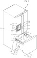
Fig. 1 is a perspective view of a refrigerator provided with a drawer withdrawing and inserting structure according to a first embodiment of the present disclosure. -
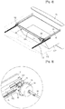
Fig. 2 is a perspective view showing a storage box assembly for a refrigerator provided with the drawer withdrawing and inserting structure in a withdrawn state. -
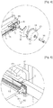
Fig. 3 is a perspective view of a drawer withdrawing apparatus according to an embodiment of the present disclosure. -
Fig. 4 is an exploded perspective view of the drawer withdrawing apparatus. -
Fig. 5 is a partial perspective view showing the configuration at the other end of a suspended portion according to the present disclosure. -
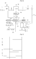
Fig. 6 is a block diagram of a driving system for a drawer of a refrigerator according to embodiments of the present disclosure. -
Fig. 7 is a waveform chart showing the shape of a pulse signal detected by a hall sensor according to forward/reverse rotation of a drive motor. -
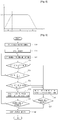
Fig. 8 is a graph showing the moving speed of a drawer of a refrigerator according to present embodiments during withdrawal of the drawer. -
Fig. 9 is a flowchart illustrating a method of driving a drawer of a refrigerator according to an embodiment of the present invention, i.e., a method for automatically withdrawing and inserting the drawer in accordance with a user's intention. -
Fig. 10 is a flowchart illustrating a general method of driving a drawer of a refrigerator according to a first embodiment of the present invention, i.e., a method for controlling movement of the drawer in accordance with a user's intention using a FG pulse signal generated by a motor controller. -
Fig. 11 is a flowchart illustrating a method of driving a drawer of a refrigerator according to a second embodiment of the present invention, i.e., a method for controlling movement of the drawer in accordance with a user's intention using a distance detection sensor. - Below, detailed descriptions of embodiments according to the present disclosure will be provided with reference to the drawings. However, it should be understood that the spirit and scope of the principles of this disclosure will not be limited to embodiments provided herein, and that alternate embodiments included in other retrogressive inventions or falling within the spirit and scope of the present disclosure can easily be derived through adding, altering, or deleting other elements.
-
Fig. 1 is a perspective view of a refrigerator provided with a drawer withdrawing and inserting structure according to a first embodiment of the present disclosure, andFig. 2 is a perspective view showing a storage box assembly for a refrigerator provided with the drawer withdrawing and inserting structure in a withdrawn state. - Referring to
Figs. 1 and2 , arefrigerator 10 according to an embodiment of the present disclosure includes a main body 11 provided with a refrigeration compartment (not shown) and afreezer compartment 111 therein, a refrigeration compartment door 12 rotatably installed on the front of the main body 11 to open and close the refrigeration compartment, and adrawer 13 provided below the refrigeration compartment to be capable of being inserted into and withdrawn from the inside of thefreezer compartment 111. - In detail, the
drawer 13 includes adoor 131 constituting the front exterior of the drawer and for opening and closing thefreezer compartment 111, and astorage box 132 provided behind thedoor 131 to store food in. - Also, the
refrigerator 10 includes aframe 15 extending rearward from the rear of thefreezer compartment door 131 to support thestorage box 132, and arail assembly 16 for allowing thestorage box 132 to be inserted into and withdrawn from thefreezer compartment 111. In detail, one end of therail assembly 16 is fixed to the inner periphery of thefreezer compartment 111, and the other end is fixed to theframe 15 allowing the rail assembly to be adjusted in length. - Also, the
refrigerator 10 further includes an anti-wobble apparatus for preventing wobbling when thestorage box 132 is being withdrawn or inserted, arail guide 17 provided at either side of thefreezer compartment 111 to hold therail assembly 16, and a withdrawing apparatus for automatically withdrawing and inserting thestorage box 132. In detail, the anti-wobble apparatus includes a suspendedportion 18 coupled to the rear of theframe 15 to prevent lateral wobbling when thestorage box 132 is being withdrawn or inserted, and a guide member provided on therail guide 17 to guide the movement of the suspendedportion 18. In further detail, arail mounting recess 171 is formed in therail guide 17 to receive therail assembly 16. Also, aguide rack 172 corresponding to the guide member is elongatedly formed from front to rear at the bottom of therail mounting recess 171. - The suspended
portion 18 includes ashaft 181 with either end connected to each of the pair offrames 15, respectively, and apinion 182 provided respectively at either end of theshaft 181. A plurality of gears is formed on the outer peripheral surface of thepinion 182, and gear teeth are formed on the upper surface of theguide 172 rack for thepinion 182 to engage with and move along. Accordingly, when thepinion 182 rotates in an engaged state with theguide rack 172, thedrawer 13 is not biased to the left or right, but is withdrawn in a straight path. Also, while thedrawer 13 is being withdrawn, it can be prevented from wobbling laterally. - Additionally, a drawer withdrawing apparatus is provided in the
refrigerator 10 to automatically withdraw thedrawer 13. - In detail, the drawer withdrawing apparatus includes a driving force generator provided on one or all of the pair of
pinions 182 to impart rotational force to thepinions 182, and a driving force transmitter for transmitting the driving force generated by the driving force generator to allow thestorage box 132 to be withdrawn. Here, the driving force generator may be adrive motor 20 that provides rotational force to thepinions 182. Also, the driving force transmitter may be an anti-wobble apparatus formed of the suspendedportion 18 and theguide rack 172. That is, the anti-wobble apparatus functions to prevent lateral wobbling of thedrawer 13, while also functioning as a driving force transmitter for automatically withdrawing thedrawer 13. The driving force generator moves integrally with thefreezer compartment door 131. Here, the driving force generator is not limited to thedrive motor 20, and may include any driving means capable of automatically withdrawing thedrawer 13, such as an actuator of the storage box employing a solenoid. - In addition, a
distance detection sensor 24 for detecting a withdrawal/insertion distance of thedrawer 13 may be mounted on an outer circumference of thedrive motor 20. In more detail, thedistance detection sensor 24 may be a sensor using infrared rays or ultrasonic waves. Other types of sensors may be used as thedistance detection sensor 24. Thedistance detection sensor 24 is mounted to detect a distance difference between the drawer and the rear wall of the freezer compartment in which the drawer is received. - If the
distance detection sensor 24 is the infrared sensor, thedistance detection sensor 24 includes a light emitting unit and a light reception unit. The infrared signal emitted from the light-emitting unit collides with the rear wall of the freezer compartment and is reflected to the light reception unit. The main controller determines the distance between thedrawer 13 and the rear wall of the inner case using a voltage value of the infrared signal detected by the light reception unit. If the distance detection sensor is the ultrasonic wave sensor, the distance is determined through the same process. Since the infrared and ultrasonic wave sensors are well known in the art, a detailed description of the distance detection method will be omitted herein. That is, it is a feature of the present invention that the withdrawal/insertion distance of the drawer is determined by the distance detection sensor. - Further, the
rail assembly 16 includes a fixedrail 161 fixed to therail mounting recess 171, a movingrail 162 fixed to theframe 15, and an extendingrail 163 connecting the fixedrail 161 and the movingrail 162. - In detail, the fixed
rail 161, the movingrail 162, and the extendingrail 163 are connected to be capable of withdrawing in stages. Depending on the front-to-rear length of thestorage box 132, the extendingrail 163 may be provided singularly or in plurality in therail assembly 16. Therail assembly 16 may be configured only with the fixedrail 161 and the movingrail 162. Also, theshaft 181 and thedrive motor 20 configuring the suspendedportion 18 may be fixed at the rear of theframe 15 or may be fixed to the rear of the movingrail 162, depending on the type of design. - The
storage box 132 is detachably coupled to theframe 15, allowing a user to periodically clean thestorage box 132. - A
dispenser 19 for dispensing water or ice may be provided at the front of the refrigeration compartment door 12. - In detail, a vessel receptacle 193 is recessed a predetermined depth into a portion of the front surface of the
dispenser 19. Anice chute 194 through which ice is dispensed and a dispensing tap (not shown) for dispensing water are provided at the ceiling of the vessel receptacle 193. A dispensinglever 195 for dispensing ice is provided to the rear of theice chute 194. Awater pan 196 is provided on the floor of the vessel receptacle 193. Also provided to one side of thedispenser 19 are adisplay 191 for displaying various data such as the operating state of the refrigerator and the temperature inside the refrigerator, and abutton panel 192 including an ice dispensing button orinput button 192a for inputting withdrawing and inserting commands for the storage box. - In further detail, the
input button 192a for entering a command to withdraw or insert the storage box may be provided in various formats such as a capacitive switch employing changes in electrostatic capacitance, a widely used tact switch, or a toggle switch. - Additionally, the
input button 192a may be provided at one side of thedisplay 19, or may alternatively be provided in a touch button configuration on the front or side surface of thefreezer compartment door 131. - Also, the
input button 192a may be provided at a side on the front surface of thefreezer compartment door 131, and may be a vibration sensor switch that operates by detecting vibrations transferred to thefreezer compartment door 131. That is, if a user is unable to use either hand and imparts a gentle shock with a foot to thefreezer compartment door 131, the vibration transferred from the shock may be sensed and thedrive motor 20 may be operated. -
Fig. 3 is a perspective view of a drawer withdrawing apparatus according to an embodiment of the present disclosure, andFig. 4 is an exploded perspective view of the drawer withdrawing apparatus. - Referring to
Figs. 3 and4 , a driving force generator forming a drawer withdrawing apparatus according to an embodiment of the present disclosure may be thedrive motor 20, and thedrive motor 20 is integrally coupled to the suspendedportion 18. - In detail, the anti-wobble apparatus may be formed of the suspended
portion 18 and theguide rack 172, and the suspendedportion 18 may be formed of ashaft 181 andpinion 182, as described above. Here, while theguide rack 172 and thepinion 182 form the anti-wobble apparatus according to the first embodiment, they may be designed to be structurally different, as long as they perform the anti-wobble function. For example, a roller enveloped with a friction member instead of thepinion 182 around its outer periphery may be applied, and a friction member contacting the roller instead of theguide rack 172 to generate friction may be applied. In other words, any configuration such as that of thepinion 182 and theguide rack 172 may be employed that enables the rolling member to rotate forward and rearward in contact with the guide member without any slippage. - The
drive motor 20 may be an inner rotor type motor, and thepinion 182 may be connected to amotor shaft 22 connected to the rotor. Thedrive motor 20 may be any motor capable of both forward and reverse rotation and variable speed operation. - In detail, a rotor and stator forming the
drive motor 20 are protected by ahousing 21. Afastening mount 31 extends from the rear of theframe 15 to fix thedrive motor 20 on, and thefastening mount 31 and thehousing 21 of thedrive motor 20 may be connected through abracket 30. Accordingly, the assembly of thedrive motor 20 and the suspended portion 28 is fixedly coupled to the rear of theframe 15, and thepinion 182 forms a structure that is coupled to themotor shaft 22 to be capable of rotation. - Here, various methods for fixing the
drive motor 20 to theframe 15 may be proposed, which will all fall within the spirit and scope of the present disclosure. Also, thedrive motor 20 may be fixed to the rear of the movingrail 162 instead of to theframe 15. In other words, thedrive motor 20 may be integrally formed with theframe 15, and the spirit and scope of the present disclosure include any structural assembly that moves forward and rearward together with thestorage box 132 and thefreezer compartment door 131. -
Fig. 5 is a partial perspective view showing the configuration at the other end of a suspended portion according to the present disclosure. - Referring to
Fig. 5 , in the present embodiment, thedrive motor 20 has been described as being provided only on an end of one side of the suspendedportion 18. However, the driving force generator, or thedrive motor 20 may be provided on each of a pair ofpinions 182, respectively. - In detail, the
pinion 182 is also rotatably coupled to the other end of the suspendedportion 18. If thedrive motor 20 is not connected, theshaft 181 may be made to pass through thepinion 182 and insert into theframe 15. In other words, thebracket 30 is provided at the rear of theframe 15, and theshaft 181 may be passed through thepinion 182 and inserted in thebracket 30. Thus, both ends of the suspendedportion 18 can be securely coupled to theframe 15, to prevent disengagement of one end of thestorage box 132 from theframe 15 or lateral wobbling of thestorage box 132 during withdrawal and insertion of thestorage box 132. - In this case, the
shaft 181 may, of course, be inserted in the rear of the movingrail 162, as described above. - Below a description will be given of the automatic withdrawing process of a
storage box 132 in a refrigerator provided with a storage box withdrawing apparatus configured as above. - First, in order to withdraw the
storage box 132 to store or remove food, a user presses theinput button 192a provided at one side of thedispenser 19 or therefrigerator 10. When theinput button 192a is pressed to input a storage box withdrawing command, the command is transmitted to the controller of therefrigerator 10. The controller of therefrigerator 10 transmits an operation signal to a drive motor controller that controls the operation of thedrive motor 20. In detail, the operation signal includes directional data for moving the storage box, and moving speed data for the storage box. That is, the directional data determines which direction the drive motor is rotated, and the speed data determines the revolutions per minute (RPM) of the drive motor. - In further detail, the drive motor is driven according to the operation signal, in order to withdraw the
freezer compartment door 131 forward. Thus, thestorage box 132 can be automatically withdrawn without a user's withdrawing movement, negating the need to attach a separate handle member on the front surface of thefreezer compartment door 131. That is, thefreezer compartment door 131 may be formed with an outer cover having a flush front surface without any protrusions, an inner cover coupled to the rear of the outer cover, and an insulator interposed between the outer cover and the inner cover. - The controller of the
refrigerator 10 receives RPM data of thedrive motor 20 in real time, and calculates the withdrawing speed (m/s) of thestorage box 132. For example, using the rotating speed of thedrive motor 20 and the circumferential value of thepinion 182, the moving speed of thestorage box 132 can be calculated per unit time. Using this data, thestorage box 132 may be withdrawn at a preset speed. Regardless of the weight of food stored in thestorage box 132, thestorage box 132 can be withdrawn at a preset speed. - The
storage box 132 can be made to be continuously or intermittently withdrawn or inserted according to how theinput button 192a is manipulated. - For example, the
storage box 132 may be made to be completely withdrawn if theinput button 192a is pressed once. Also, thestorage box 132 may be made to be withdrawn in stages if theinput button 192a is pressed repeatedly with a certain interval in between pressings. - In addition, the
storage box 132 may be controlled to be automatically stopped or reinserted if it encounters an obstacle while being withdrawn. - The
storage box 132 may be controlled to be stopped when it is withdrawn a predetermined distance, and may be controlled to be either reinserted or withdrawn completely according to the user's intentions. In other words, with thestorage box 132 stopped after being withdrawn a predetermined distance, thestorage box 132 may be completely withdrawn when it is sensed that a user pulls thefreezer compartment door 131, or thestorage box 132 may be inserted if it is sensed that a user pushes thefreezer compartment door 131. - If the
storage box 132 is not withdrawn or stops during withdrawal when a storage box withdrawal command is input through theinput button 192a, this may be sensed and an error signal may be generated. - The
storage box 132 of a refrigerator according to present embodiments is characterized in that it can not only be automatically withdrawn, but withdrawn manually as well. For example, in the event of a power outage where power cannot be supplied to thedrive motor 20 or when a user does not manipulate theinput button 192a but grasps and pulls thefreezer compartment door 131 by hand, thestorage box 132 is not subjected to resistance from thedrive motor 20 and can be smoothly withdrawn. In other words, even when thedrive motor 20 does not operate, withdrawing of the storage box is not impeded by thedrive motor 20. - The
storage box 132 may be controlled so that it is automatically closed when left in a withdrawn state exceeding a predetermined duration, in order to minimize cold air loss. - As an alternative to the
drive motor 20 being configured with signal wires connecting to the controller of therefrigerator 10 and electrical wires for supplying current, a charging apparatus may be provided at a side of thedrive motor 20, and a short range wireless transmitter-receiver system may be installed to enable omission of signal wires and electrical wires. -
Fig. 6 is a block diagram of a driving system for a drawer of a refrigerator according to embodiments of the present disclosure. - Referring to
Fig. 6 , adrawer driving system 800 according to the present disclosure includes amain controller 810 that controls the overall operation of therefrigerator 10, amotor controller 860 controlling the driving of thedrive motor 20, aninput unit 840 for inputting commands for withdrawing and inserting the drawer to themain controller 810, a display displaying the operating state of therefrigerator 10, awarning unit 830 that issues a warning when a system error occurs during operation of therefrigerator 10, amemory 850 that stores various data input through themotor controller 860 and theinput unit 840, a switched-mode power supply SMPS (880) that applies power to various electrical components to operate therefrigerator 10, and a rotatingdirection detecting unit 870 that outputs a LOW or HIGH signal according to whether thedrive motor 20 is rotating forward or in reverse. As described above, thedistance detection unit 890 may be the infrared sensor or the ultrasonic wave sensor. - In detail, the
drive motor 20 is formed of a stator and a rotor, and may be a 3-phase brushless direct current (BLDC) motor with 3 hall sensors (HU,HV,HW) 23 provided on the rotor. Themotor controller 860 includes an driver integrated circuit (IC) 862 that receives a motor driving signal input from themain controller 810 to control the operation of thedrive motor 20, and aninverter 861 that receives a DC voltage applied from theSMPS 880 and applies a 3-phase current to thedrive motor 20 according to a switching signal transmitted from thedriver IC 862. - Below, the operation of the driving system for the drawer will be described.
- First, the
SMPS 880 transforms and rectifieshousehold SMPS 880. Theinverter 861 switches the DC voltage applied by theSMPS 880 to generate a 3-phase AC voltage of a sine waveform. The 3-phase AC voltage output from theinverter 861 includes a U-phase, a V-phase, and a W-phase voltage. - As the
drive motor 20 is a BLDC motor provided withhall sensors 23, power is applied to thedrive motor 20 to rotate the rotor - i.e., a switching signal is transmitted from thedriver IC 862 to theinverter 861, and theinverter 861 applies a voltage respectively to three coil windings U, V, and W wound around the stator according to the switching signal having a 120
∘
phase shift. Further description hereof will not be provided, since it is well known to those skilled in the art. - Specifically, through a drawer withdrawal command input through the
input unit 840 by a user, themain controller 810 transmits a speed command signal VSP for thedrive motor 20 to themotor controller 860 and transmits a rotation direction command signal CW/CCW. The speed command and rotation direction command signals are transmitted to themotor controller 860 to rotate thedrive motor 20. - During the rotating of the
drive motor 20, thehall sensors 23 generate detecting sensors, or pulses, corresponding in number to the number of poles of the permanent magnets provided on the rotor. For example, if the number of poles of the permanent magnet provided on the rotor is 8, then 24 pulses are generated for every rotation of thedrive motor 20. - In detail, the pulse signals generated by the
hall sensors 23 are transmitted to thedriver IC 862 and the rotatingdirection detecting unit 870. The rotationdirection sensing unit 870 uses the pulse signals to detect the rotating direction of thedrive motor 20, and transmits the detected data to themain controller 810. - The
driver IC 862 uses the pulse signals to generate a frequency generator (FG) pulse signal. That is, in an FG circuit provided within thedriver IC 862, the pulse signals output from thehall sensors 23 are used to generate and output FG pulse signals corresponding to the number of rotations of thedrive motor 20. For example, assuming that there are A numbers of FG pulse signals for every rotation of thedrive motor 20, if B numbers of FG pulse signals have been generated during withdrawal of thedrawer 13, the number of rotations of the drive motor is B/A. Also, because the rotation direction of thedrive motor 20 can be sensed by the rotatingdirection detecting unit 870, the number of FG pulse signals can be counted as a positive value when the rotating direction of thedrive motor 20 is forward, and the number can be counted as a negative value for reverse rotation. Thus, the absolute position of thedrive motor 20 or thedrawer 13 can be determined, and it can easily be determined whether a consumer has pulled or pushed thedrawer 13. Here, thememory 850 of themain controller 810 stores data on the number of FG pulse signals according to the moved distance of thedrawer 13 as a table. - FG pulse signals that are output are transmitted to the
main controller 810. Themain controller 810 uses the transmitted FG pulse signals to calculate the rotating speed of thedrive motor 20. Also, by using the rotating speed and time of thedrive motor 20, the moved speed and distance of thedrive motor 20, or the moved speed and distance of the drawer can be calculated. -
Fig. 7 is a waveform chart showing the shape of a pulse signal detected by a hall sensor according to forward/reverse rotation of a drive motor. - Referring to
Fig. 7 , when the rotor of thedrive motor 20 rotates as shown, pulse signals are detected by therespective hall sensors 23, as shown inFig. 10 . That is, when thedrive motor 20 rotates in a forward direction, the pulse signals are detected in the sequence HU→HV→HW, and the pulse signals are detected in the sequence HU→HW →HV for reverse rotation. - Further, the rotating
direction detecting unit 870 compares a portion of the above signals sensed by the hall sensors to a zero-level reference value, and determines the rotating direction of thedrive motor 20. - In detail, the rotating
direction detecting unit 870 includes: afirst comparator 871 that compares a first signal output from thehall sensors 23 with a reference signal; asecond comparator 872 that compares a second signal output from thehall sensors 23 to a reference signal; a D-flip flop 874 that designates a signal output from thefirst comparator 871 as an input signal D, inverts a signal output from thesecond comparator 872 and performs logic-combining to yield a clock signal CK, and outputs corresponding signals as output signals; athird comparator 873 that compares and outputs two driving voltages Ec and Ecr that are variable according to kick, brake, and other controlling of thedrive motor 20; and an Andgate 875 that logic-combines an output of the D-flip flop 874 with an output of thethird comparator 873 to an And. - Through the thus-configured rotating
direction detecting unit 870, the Andgate 875 outputs a high signal when the drive motor rotates in reverse, and outputs a low signal when the drive motor rotates in a forward direction. The high signal or low signal is transmitted to themain controller 810, and themain controller 810 stores data on the current rotation direction of thedrive motor 20 in thememory 850. The FG pulse signal transmitted from thedriver IC 862 is also stored in thememory 850. -
Fig. 8 is a graph showing the moving speed of a drawer of a refrigerator according to present embodiments during withdrawal of the drawer. - Referring to
Fig. 8 , a drive motor for withdrawing a drawer according to present embodiments moves integrally with thedrawer 13, so that the moving speed and distance of the drawer denotes the moving speed and distance of the drive motor. - As shown, when a drawer withdrawal command is input, the drawer increases in speed as it moves at an acceleration (a) until it attains a preset speed (VSET). When it reaches the preset speed, it moves at a constant speed (b). A predetermined time before a reference point at which the drawer completely opens, the
drawer 13 reduces speed at a deceleration (c). This is to prevent thedrawer 13 from continuing to accelerate until it is completely open, thus preventing thedrawer 13 from generating a noisy "thunk" at the completion of its opening and damage to the drawer withdrawing apparatus. Here, the accelerating region occupies a relatively small portion of the overall drawer withdrawal. - Of course, the process of closing the
drawer 13 from a completely open state also involves the same speed distribution as in the opening process. - Due to the weight of food stored in the
drawer 13, withdrawing or inserting of thedrawer 13 may be unable to maintain a regular speed distribution. That is, when a predetermined voltage is applied to thedrive motor 20, the withdrawing speed may vary depending on the weight of thedrawer 13, so that reliability in consistency and speed cannot be ensured. - However, the present disclosure is characterized by providing a controlling method for withdrawing or inserting a
drawer 13 consistently at a preset speed distribution, regardless of the effects from varying weights of food stored in thedrawer 13. - Embodiments of the present disclosure provide a controlling method for withdrawing or inserting a drawer of a refrigerator consistently at a preset speed distribution, regardless of the weight of stored food, which is described below.
- First, a user presses an input button that inputs a drawer withdrawal command. The drawer withdrawal command is transmitted to the main controller. Then, the main controller transmits commands to the motor controller, namely, a command for the rotating speed and a command for the rotating direction of the motor to the driver IC.
- The speed and directional commands are transmitted from the driver IC of the motor controller to the inverter as a switching signal corresponding to the command transmitted from the main controller. Thus, current in the inverter is applied with respective phase shifts between three coils wound around the stator of the motor, in accordance to the input switching signal. Therefore, magnetic fields are generated at the stator coils by means of the current to rotate the rotor. The intensity of the magnetic fields formed at the rotor is detected by the hall sensors, and each switching device is sequentially turned ON/OFF according to the detected magnetic field intensities to continuously rotate the rotor and drive the drive motor.
- Data on the rotating speed and rotating direction of the rotor of the motor is transmitted to the main controller according to the driving of the drive motor. In detail, when the rotor of the drive motor rotates, pulse signals HU,HV, and HW are generated by 3 hall sensors, respectively, arranged a predetermined distance apart from one another on the stator. Also, the pulse signals are transmitted to the driver IC and the rotating direction detecting unit. The pulse signal transmitted to the driver IC generates an FG pulse signal by means of the FG generating circuit and is transmitted to the main controller. The pulse signal transmitted to the rotating direction detecting unit is detected in terms of the rotating direction of the rotor by a rotating direction detecting circuit, and is transmitted to the main controller.
- The rotating speed (rpm) of the drive motor is detected from the transmitted FG pulse signal by the main controller. The moving speed and moving distance of the drive motor is calculated from the detected rotating speed of the drive motor.
- In detail, the moving speed of the drive motor (or moving speed of the drawer) can be derived from the following equations.


- The moving distance of the drive motor can be derived from the moving speed of the drive motor over a set duration.
-
Fig. 9 is a flowchart illustrating a method of driving a drawer of a refrigerator according to an embodiment of the present invention, i.e., a method for automatically withdrawing and inserting the drawer in accordance with a user's intention. - Referring to
Fig. 9 , a control method that will be described hereinafter is performed in a state where the drawer is withdrawn by a predetermined distance and stops by a drawer withdrawal command. That is, in a state where the drawer is withdrawn by the predetermined distance, themain controller 181 determines a user's intention in accordance with a user's action to further withdraw or insert the drawer. - In more detail, when a drawer opening command is input by the user (S30), the
drawer 13 is withdrawn by a predetermined distance (S31). The predetermined distance is shorter than a distance when the drawer is fully withdrawn. - It is also determined if a drawer stop duration reaches a predetermined time (S33). When no external force is applied to the
drawer 13 until the drawer stop duration reaches the predetermined time, thedrive motor 20 rotates in a reverse direction to close the drawer 13 (S36). When the drawer is completely closed (S37), the drive motor stops operating (S40). - The
main controller 810 detects in real time if the external force is applied to thedrawer 13 until the drawer stop duration reaches the predetermined time (S34). - The external force indicates force applied by the user to the
drawer 13 to insert or further withdraw thedrawer 13. The external force may be applied and released in short time. That is, external force generated by the user tapping or lightly touching thedrawer 13. - When no external force is applied to the
drawer 13, thedrawer 13 maintains its stopping state and the stopping time is integrated. When the external force is applied to thedrawer 13, it is determined if the external force is applied in a drawer opening direction or a drawer closing direction (S35). The external force application direction is detected by thedistance detection sensor 24 or by the variation of the FG pulse signal. - When the external force is applied in the drawer opening direction, the drive motor rotates in the drawer opening direction (S38). When the external force is applied in the drawer closing direction, the drive motor rotates in the drawer closing direction (S36). In addition, it is determined if the drawer is fully closed or not (S37) or it is determined if the drawer if fully opened or not (S39). The drive motor stops rotating (S40) or keeps rotating depending on a detection result.
- Here, the detection of the full opening or full closing of the drawer may be realized by analyzing the FG pulse signal or using the
distance detection sensor 24. In addition, methods may be used to detect the full opening or full closing of the drawer. For example, a detection unit provided on a typical refrigerator may be used. That is, the full opening or full closing of the drawer may be detected by an on/off switch providing on a rear surface of the door and a front surface of the main body. -
Fig. 10 is a flowchart illustrating a general method of driving a drawer of a refrigerator according to a first embodiment of the present invention, i.e., a method for controlling movement of the drawer in accordance with a user's intention using a FG pulse signal generated by a motor controller. - Referring to
Fig. 10 , the drawer opening command is input by the user (S50) and the drawer is opened (S51). Information on the FG pulse signal and the drawing moving direction that is generated in the middle of moving thedrawer 13 are transferred to themain controller 810. When thedrawer 13 stops at the predetermined distance (S53), the information on the FG pulse signal and the motor rotational direction at the stop location is stored in the memory (S54). - When the drawer moves by the external force (S55), the
main controller 810 calculates a variation of the FG pulse signal in accordance with the movement of the drawer (S56). In more detail, when the drawer moves, thepinion 182 rotates and themotor shaft 22 connected to thepinion 182 rotates together. As themotor shaft 22 rotates, the pulse signal is generated through thehall sensor 23 and the driver IC generates the FG pulse signal using the pulse signal. - Meanwhile, the variation of the FG pulse signal is a positive value when the motor rotates a forward direction and is a negative value when the motor rotates a reverse direction.
- It is determined if the drawer moves in the opening direction or the closing direction depending on the variation of the FG pulse signal (S57). When it is determined that the drawer moves in the opening direction, the drive motor rotates in the drawer opening direction. When it is determined that the drawer moves in the closing direction, the drive motor rotates in the drawer closing direction (S58). It is determined if the drawer is fully opened or not (S61) or fully closed or not (S59), in accordance with a result of which, the drive motor stops operating (S62) or keeps rotating.
-
Fig. 11 is a flowchart illustrating a method of driving a drawer of a refrigerator according to a second embodiment of the present invention, i.e., a method for controlling movement of the drawer in accordance with a user's intention using a distance detection sensor. - Referring to
Fig. 11 , like the first embodiment, the drawer opening command is input (S70) and the drawer is opened depending on the input command (S71). - In more detail, the drawer moving distance is detected by the
distance detection sensor 24 in the middle of opening the drawer (S72). The drawer stops at the predetermined distance (S73). The drawer location information at a time point where the drawer stops is stored in the memory (S74). - Meanwhile, when the drawer moves by the external force (S75), the
distance detection sensor 24 detects a variation. That is, thedistance detection sensor 24 detects a location variation of the drawer. - In more detail, the
main controller 810 compares current location information with the location information that is lastly stored in the memory, through which themain controller 810 determines if the drawer moves in the opening direction or the closing direction (S77). - In more detail, when it is determined that the drawer moves in the opening direction, the
drive motor 20 rotates in the forward direction (S89) to fully open the drawer. When it is determined that the drawer moves in the closing direction, thedrive motor 20 rotates in the reverse direction (S78) to fully close the drawer. The drive motor stops rotating (S82 or keeps rotating depending on whether the drawer is fully opened (S81) or closed (S79). - In the above embodiments, although the drawer moves in accordance with the user's intention in a state where the drawer is withdrawn by a predetermined distance and stops, the present invention is not limited to the embodiments. That is, the method can be identically applied when the drawer is in a fully closed state or a fully opened state. In more detail, when the drawer is in the fully closed state and the user applies the external force in the drawer opening direction, the controller detects this to automatically open the drawer. When the drawer is in the fully opened state and the user applies the external force in the drawer closing direction, the controller detects this to automatically close the drawer.
- In more detail, when the drawer is fully closed, the FG pulse signal value becomes 0 when the drawer is fully closed and the rotational direction of the drive motor is detected from the pulse value of the hall sensor generated when the drawer starts being opened. The controller detects the drawer moving direction.
- When the drawer is fully closed, the pulse signal is calculated as the positive value and stored in the memory and the rotational direction of the drive motor is detected from the pulse value of the hose sensor when the drawer starts being closed. The controller detects the drawer moving direction and the FG pulse value will be integrated as the negative value in the middle of moving the drawer.
- In other embodiments, the user may input a full opening command or a full closing command through an input button. That is, in a state where the drawer is opened by a predetermined distance, the user loads the goods (food) and inputs the closing command through the input button. Then, the
drive motor 20 rotates in the reverse direction to close the drawer. When it is determined that there is a need to fully open the drawer for the loading of the goods, the user may input the full opening command through the input button. Then, thedrive motor 20 rotates in the forward direction to fully open the drawer. - By the above described system and method for driving the drawer of the refrigerator, the drawer can be automatically opened and closed in accordance with the user's intention in a state where the drawer is opened to a predetermined distance. It follows a list of examples:
- [1] A method of driving a drawer of a refrigerator, the method comprising: detecting external force applied to the drawer that is in a stationary state; transferring an external force detecting signal to a controller; and determining an application direction of an external force; moving the drawer in the application direction of the external force.
- [2] The method according to example 1, wherein the stationary state includes a stationary state where the drawer is fully closed, a stationary state where the drawer is opened to a predetermined distance, and a stationary state where the drawer is fully opened.
- [3] The method according to example 1, wherein the external force applied to the drawer is detected by a pulse signal that is output from a hall sensor of a drive motor when the drawer moves.
- [4] The method according to example 3, wherein the application direction of the external force to the drawer is determined by detecting a rotational direction of the drive motor using the pulse signal.
- [5] The method according to example 1, wherein a drawer moving velocity and distance are calculated by analyzing a FG pulse signal of the drive motor, which is generated depending on motion of the drawer.
- [6] The method according to example 5, wherein the application direction of the external force to the drawer and an absolute location of the drawer are determined by calculating a variation of the FG pulse signal.
- [7] The method according to example 5, wherein, when the drawer rotates in a first direction, the FG pulse signal is integrated as a positive value; and when the drawer rotates in a second direction, the FG pulse signal is integrated as a negative value.
- [8] The method according to example 1, wherein the external force applied to the drawer is detected by a distance detection sensor.
- [9] The method according to example 8, wherein the application direction of the external force to the drawer is determined from a detecting value transferred from the distance detection sensor.
- [10] The method according to example 1, wherein, when there is no external force in a pre-determined time after the drawer stops moving, the drawer is automatically closed.
- [11] The method according to example 1, wherein the drawer is automatically opened by a drawer opening command input through an input button or is manually opened by a user.
- [12] A drawer driving system of a refrigerator, comprising: a drive motor that rotates to withdraw a drawer to a predetermined distance; and a controller for controlling an operation of the drive motor, wherein the controller controls the operation of the drive motor such that the drawer moves in a direction in which an external force is applied to the drawer in a state where the drawer stops.
- [13] The drawer driving system according to example 12, wherein the drive motor is a BLCD motor.
- [14] The drawer driving system according to example 12, wherein the drive motor integrally moves together with the drawer.
- [15] The drawer driving system according to example 12, further comprising: a rotational direction detecting unit that is configured to detect a rotational direction of the drive motor and to transfer a detected signal to the controller; and an alarm unit that is connected to the controller to issue an alert of a malfunction of the drive motor to an outside.
- [16] The drawer driving system according to example 12, wherein the controller comprises a main control and a motor controller for receiving a driving command of the drive motor from the main controller and driving the drive motor in accordance with the driving command.
- [17] The drawer driving system according to example 16, wherein the motor controller comprises a driver IC that is designed to generate a switching signal in accordance with a driving condition of the drive motor; and an inverter that is designed to apply a current to a rotor of the drive motor in accordance with the switching signal from the driver IC.
- [18] The drawer driving system according to example 17, wherein the driving IC is designed to generate a FG pulse signal and transfer the FG pulse signal to the main controller.
- [19] The drawer driving system according to example 18, wherein the controller is designed to integrate the FG pulse signal from the driver IC as a positive or negative value.
- [20] The drawer driving system according to example 12, further comprising a distance detection unit that is provided on one of the drive motor, the drawer, and an inner case for receiving the drawer to detect a moving distance of the drawer.
- [21] The drawer driving system according to example 20, wherein the distance detection unit may be one of an infrared sensor and an ultrasonic waver sensor.
Claims (16)
- A method of driving a drawer of a refrigerator, the refrigerator comprising a drawer (13), a drive motor (20) configured to rotate for withdrawing the drawer (13) to a predetermined distance and a controller for controlling an operation of the drive motor (20), the method comprising:detecting (S34) external force applied to the drawer that is in a stationary state;transferring an external force detecting signal to a controller; anddetermining (S35) an application direction of an external force;moving (S36, S38) the drawer in the application direction of the external force.
- The method according to claim 1, wherein the stationary state includes a stationary state where the drawer is fully closed, a stationary state where the drawer is opened to a predetermined distance, and a stationary state where the drawer is fully opened.
- The method according to claim 1, wherein the external force applied to the drawer is detected by a pulse signal that is output from a hall sensor of a drive motor when the drawer moves.
- The method according to claim 3, wherein the application direction of the external force to the drawer is determined by detecting a rotational direction of the drive motor using the pulse signal.
- The method according to claim 1, wherein a drawer moving velocity and distance are calculated by analyzing a frequency generator, FG, pulse signal of the drive motor, which is generated depending on motion of the drawer.
- The method according to claim 5, wherein the application direction of the external force to the drawer and an absolute location of the drawer are determined by calculating a variation of the FG pulse signal (S56).
- The method according to claim 5, wherein, when the drawer rotates in a first direction, the FG pulse signal is integrated as a positive value; and when the drawer rotates in a second direction, the FG pulse signal is integrated as a negative value.
- The method according to claim 1, wherein the external force applied to the drawer is detected by a distance detection sensor (24, 890).
- The method according to claim 8, wherein the application direction of the external force to the drawer is determined from a detecting value transferred from the distance detection sensor.
- The method according to claim 1, wherein, when there is no external force in a predetermined time after the drawer stops moving, the drawer is automatically closed.
- The method according to claim 1, wherein the drawer is automatically opened by a drawer opening command (S30, S50, S70) input through an input button or is manually opened by a user.
- The method according to claim 1, wherein the drive motor integrally moves together with the drawer.
- The method according to claim 1, further comprising: detecting a rotational direction of the drive motor by a rotational direction detecting unit and transferring the detected signal to the controller; and outputting an alarm signal of a malfunction of the drive motor to an outside by an alarm unit, when the drive motor malfunctions.
- The method according to claim 12, wherein the controller comprises a main controller (810) and a motor controller (860), wherein a driving command of the drive motor is transferred to the motor controller from the main controller and the drive motor is driven in accordance with the driving command,
wherein the motor controller comprises a driver IC (862) and an inverter (861), wherein the driver IC is controlled to generate a switching signal in accordance with a driving condition of the drive motor and the inverter is controlled to apply a current to a rotor of the drive motor in accordance with the switching signal from the driver IC. - The method according to claim 8 or 9, wherein the distance detection sensor is provided on one of the drive motor, the drawer, and an inner case for receiving the drawer and comprises at least one of one of an infrared sensor and an ultrasonic waver sensor.
- The method according to claim 1, further comprising determining if the drawer is fully closed or not (S37) or if the drawer is fully opened or not (S39), wherein the drive motor stops rotating or keeps rotating depending on a detection result.
Priority Applications (2)
| Application Number | Priority Date | Filing Date | Title |
|---|---|---|---|
| EP19175585.9A EP3553434B1 (en) | 2008-03-26 | 2008-03-26 | Method for driving a drawer in a refrigerator |
| ES19175585T ES2888655T3 (en) | 2008-03-26 | 2008-03-26 | Procedure for activating a drawer in a refrigerator |
Applications Claiming Priority (3)
| Application Number | Priority Date | Filing Date | Title |
|---|---|---|---|
| EP19175585.9A EP3553434B1 (en) | 2008-03-26 | 2008-03-26 | Method for driving a drawer in a refrigerator |
| EP08723732.7A EP2283293B1 (en) | 2008-03-26 | 2008-03-26 | Method for driving a drawer in a refrigerator |
| PCT/KR2008/001696 WO2009119923A1 (en) | 2008-03-26 | 2008-03-26 | System and method for driving a drawer in a refrigerator |
Related Parent Applications (1)
| Application Number | Title | Priority Date | Filing Date |
|---|---|---|---|
| EP08723732.7A Division EP2283293B1 (en) | 2008-03-26 | 2008-03-26 | Method for driving a drawer in a refrigerator |
Publications (2)
| Publication Number | Publication Date |
|---|---|
| EP3553434A1 true EP3553434A1 (en) | 2019-10-16 |
| EP3553434B1 EP3553434B1 (en) | 2021-07-28 |
Family
ID=41114093
Family Applications (2)
| Application Number | Title | Priority Date | Filing Date |
|---|---|---|---|
| EP19175585.9A Active EP3553434B1 (en) | 2008-03-26 | 2008-03-26 | Method for driving a drawer in a refrigerator |
| EP08723732.7A Active EP2283293B1 (en) | 2008-03-26 | 2008-03-26 | Method for driving a drawer in a refrigerator |
Family Applications After (1)
| Application Number | Title | Priority Date | Filing Date |
|---|---|---|---|
| EP08723732.7A Active EP2283293B1 (en) | 2008-03-26 | 2008-03-26 | Method for driving a drawer in a refrigerator |
Country Status (6)
| Country | Link |
|---|---|
| US (1) | US8148932B2 (en) |
| EP (2) | EP3553434B1 (en) |
| KR (1) | KR101476859B1 (en) |
| CN (1) | CN101981397B (en) |
| ES (1) | ES2888655T3 (en) |
| WO (1) | WO2009119923A1 (en) |
Families Citing this family (41)
| Publication number | Priority date | Publication date | Assignee | Title |
|---|---|---|---|---|
| WO2009119924A1 (en) | 2008-03-26 | 2009-10-01 | Lg Electronics Inc. | Refrigerator, system and method for driving a drawer of the refrigerator |
| US8217613B2 (en) | 2008-03-26 | 2012-07-10 | Lg Electronics Inc. | System and method for driving a drawer of a refrigerator and refrigerator employing same |
| CN101981396A (en) * | 2008-03-26 | 2011-02-23 | Lg电子株式会社 | System and method for driving a drawer in a refrigerator |
| KR101380557B1 (en) | 2008-03-26 | 2014-04-01 | 엘지전자 주식회사 | System and method for driving a drawer in a refrigerator |
| EP2283290A4 (en) * | 2008-03-26 | 2014-01-15 | Lg Electronics Inc | Refrigerator |
| KR101476859B1 (en) | 2008-03-26 | 2014-12-24 | 엘지전자 주식회사 | System and method for driving a drawer in a refrigerator |
| KR101441133B1 (en) * | 2008-03-26 | 2014-09-17 | 엘지전자 주식회사 | Controlling method for driving drawer of refrigerator |
| KR101592575B1 (en) * | 2009-03-20 | 2016-02-05 | 엘지전자 주식회사 | Refrigerator |
| KR101592574B1 (en) * | 2009-03-20 | 2016-02-05 | 엘지전자 주식회사 | A refrigerator for controlling refrigerator |
| KR101592573B1 (en) * | 2009-03-20 | 2016-02-05 | 엘지전자 주식회사 | A refrigerator |
| KR101592571B1 (en) * | 2009-03-20 | 2016-02-05 | 엘지전자 주식회사 | A refrigerator for controlling refrigerator |
| KR101592572B1 (en) * | 2009-03-20 | 2016-02-05 | 엘지전자 주식회사 | A refrigerator for controlling refrigerator |
| AT507656B1 (en) * | 2009-05-13 | 2010-07-15 | Blum Gmbh Julius | ARRANGEMENT FOR LOCKING AND EJECTING A FURNITURE PART |
| KR101831614B1 (en) | 2010-01-28 | 2018-02-26 | 삼성전자주식회사 | Refrigerator |
| CN102564046B (en) * | 2012-02-15 | 2013-11-13 | 合肥美的电冰箱有限公司 | Refrigerator |
| CN102538372B (en) * | 2012-02-15 | 2014-03-26 | 合肥美的电冰箱有限公司 | Sliding rail mechanism for refrigerator and refrigerator with sliding rail mechanism |
| CN102564045B (en) * | 2012-02-15 | 2013-12-25 | 合肥美的电冰箱有限公司 | Supporting guide rail used for refrigerator |
| DE102013226910A1 (en) * | 2013-12-20 | 2015-06-25 | BSH Hausgeräte GmbH | Lifting device and water-conducting household appliance |
| DE102014115773A1 (en) * | 2014-10-30 | 2016-05-04 | Miele & Cie. Kg | Refrigerator such as fridge and / or freezer with door operating mechanism |
| WO2016084598A1 (en) * | 2014-11-28 | 2016-06-02 | 富士電機株式会社 | Product dispensing device |
| DE102015208830A1 (en) * | 2015-05-12 | 2016-11-17 | BSH Hausgeräte GmbH | Home appliance with a door control |
| CN107709910B (en) | 2015-11-04 | 2020-11-24 | Lg 电子株式会社 | Refrigerator with a door |
| CN106121448B (en) * | 2016-06-21 | 2018-01-23 | 南京创维家用电器有限公司 | It is a kind of to collect structure, refrigerator and the cupboard that side is opened the door and sliding door is integral |
| CN106642909B (en) * | 2016-11-11 | 2019-08-27 | 青岛海尔股份有限公司 | Refrigerator and article storing box in refrigerator |
| US10413064B1 (en) * | 2018-09-26 | 2019-09-17 | Dong Guan Song Wei Electric Technology Co., Ltd. | Electric drawer with gesture sensing |
| CN111578612A (en) * | 2019-02-15 | 2020-08-25 | 青岛海尔电冰箱有限公司 | Refrigerator drawer door control method and refrigerator |
| WO2020194659A1 (en) * | 2019-03-28 | 2020-10-01 | 三菱電機株式会社 | Refrigerator |
| KR20210007641A (en) | 2019-07-12 | 2021-01-20 | 엘지전자 주식회사 | Refrigerator having drawer type door |
| KR20210007642A (en) | 2019-07-12 | 2021-01-20 | 엘지전자 주식회사 | Refrigerator having drawer type door |
| KR20210007647A (en) | 2019-07-12 | 2021-01-20 | 엘지전자 주식회사 | refrigerator |
| KR20210007646A (en) | 2019-07-12 | 2021-01-20 | 엘지전자 주식회사 | refrigerator |
| KR20210007639A (en) | 2019-07-12 | 2021-01-20 | 엘지전자 주식회사 | Refrigerator |
| KR20210007638A (en) | 2019-07-12 | 2021-01-20 | 엘지전자 주식회사 | Refrigerator |
| KR20210007644A (en) | 2019-07-12 | 2021-01-20 | 엘지전자 주식회사 | refrigerator |
| KR20210008709A (en) | 2019-07-15 | 2021-01-25 | 엘지전자 주식회사 | Refrigerator and control method thereof |
| KR20210008707A (en) | 2019-07-15 | 2021-01-25 | 엘지전자 주식회사 | Refrigerator and control method thereof |
| CN110608572B (en) * | 2019-10-12 | 2023-10-27 | 无锡海达尔精密滑轨股份有限公司 | Single motor driving control system for electric slide rail of refrigerator drawer |
| JP7452248B2 (en) | 2020-05-25 | 2024-03-19 | Toto株式会社 | Opening aid |
| CN112696875A (en) * | 2020-12-31 | 2021-04-23 | 李丹 | Clean cooling device of energy-concerving and environment-protective of modularization |
| JP7422694B2 (en) | 2021-01-29 | 2024-01-26 | 日立グローバルライフソリューションズ株式会社 | storage room |
| CN115164485B (en) * | 2022-07-25 | 2023-12-22 | 海信冰箱有限公司 | Refrigerator and layer frame lifting control method thereof |
Citations (5)
| Publication number | Priority date | Publication date | Assignee | Title |
|---|---|---|---|---|
| JPH02103388A (en) * | 1988-10-12 | 1990-04-16 | Mitsubishi Electric Corp | Automatic case drawing device |
| JPH02136686A (en) * | 1988-11-18 | 1990-05-25 | Mitsubishi Electric Corp | Control device for drawer vessel for refrigerator |
| JPH1194455A (en) * | 1997-09-17 | 1999-04-09 | Sankyo Seiki Mfg Co Ltd | Casing and refrigerator having automatic drawer |
| EP1323363A1 (en) * | 2001-12-27 | 2003-07-02 | Julius Blum Gesellschaft m.b.H. | Device with a movable furniture part, including drive unit and control device |
| DE102005049488B3 (en) * | 2005-10-13 | 2006-11-09 | Küster Automotive Door Systems GmbH | Mechanism to open/close a sliding drawer, door or flap, has a sensor to register a manual movement and a timer to activate a drive after a given time span |
Family Cites Families (72)
| Publication number | Priority date | Publication date | Assignee | Title |
|---|---|---|---|---|
| JPH02106686A (en) | 1988-10-13 | 1990-04-18 | Mitsubishi Electric Corp | Automatic opening and closing device for draw case |
| JPH02146487A (en) | 1988-11-26 | 1990-06-05 | Mitsubishi Electric Corp | Automatic draw device for refrigerator |
| JPH0345820A (en) | 1989-07-11 | 1991-02-27 | Matsushita Electric Ind Co Ltd | Device for opening-closing door of cooker |
| US5038091A (en) * | 1989-08-11 | 1991-08-06 | Whirlpool Corporation | Electronic control for an appliance |
| US6130621A (en) * | 1992-07-09 | 2000-10-10 | Rsa Security Inc. | Method and apparatus for inhibiting unauthorized access to or utilization of a protected device |
| US5392951A (en) * | 1993-05-20 | 1995-02-28 | Lionville Systems, Inc. | Drawer operating system |
| JPH07174459A (en) | 1993-12-20 | 1995-07-14 | Hitachi Ltd | Drawer for refrigerator |
| DE29519963U1 (en) | 1995-12-16 | 1997-04-10 | Aeg Hausgeraete Gmbh | Refrigerator and / or freezer |
| US5899083A (en) * | 1997-03-12 | 1999-05-04 | Whirlpool Corporation | Multi-compartment refrigeration system |
| KR100219643B1 (en) | 1997-06-26 | 1999-09-01 | 윤종용 | Co-channel interference detector and driving method |
| DE19858387A1 (en) * | 1998-12-17 | 2000-06-21 | Bsh Bosch Siemens Hausgeraete | Refrigerator |
| EP1011184A1 (en) * | 1998-12-15 | 2000-06-21 | Talltec Technologies Holdings S.A. | Safety device for an electric motor-driven sliding panel and method for carrying out this arrangement |
| KR20010075919A (en) * | 2000-01-21 | 2001-08-11 | 구자홍 | Current limit circuit of inverter refrigerator |
| US6751909B2 (en) * | 2001-02-06 | 2004-06-22 | The Stanley Works | Automatic door control system |
| AT413185B (en) * | 2001-05-17 | 2005-12-15 | Blum Gmbh Julius | FURNITURE DRAWER |
| US6615121B2 (en) | 2001-10-19 | 2003-09-02 | Shih-Hsiung Li | Vehicle reversing sensor device |
| DE10256658A1 (en) * | 2001-12-10 | 2003-07-03 | Papst Motoren Gmbh & Co Kg | Producing alarm signal for motors for critical drive tasks, involves checking at intervals whether current revolution rate is in range outside that defined by desired and alarm switch-on rates |
| AT500362B1 (en) * | 2002-06-27 | 2007-01-15 | Blum Gmbh Julius | ARRANGEMENT WITH A MOVABLE FURNITURE AND WITH A DRIVE UNIT |
| KR200301747Y1 (en) * | 2002-10-18 | 2003-01-24 | 박윤식 | Auto guide equipment for drawer |
| CA2414195C (en) * | 2002-11-27 | 2008-12-02 | Knape & Vogt Manufacturing Co. | Interlock mechanism for lateral file cabinets |
| AU2003297585A1 (en) * | 2002-11-27 | 2004-06-23 | Knape And Vogt Manufacturing Co. | Interlock mechanism for lateral file cabinets |
| AT502574B1 (en) * | 2003-05-19 | 2007-08-15 | Blum Gmbh Julius | FURNITURE WITH A MOVABLE FURNITURE |
| AT503998B1 (en) * | 2003-05-19 | 2010-07-15 | Blum Gmbh Julius | METHOD FOR DRIVING A MOVABLE FURNITURE PART |
| KR200334077Y1 (en) * | 2003-09-01 | 2003-11-19 | 위니아만도 주식회사 | The opening apparatus of drawer room at kim-chi storage |
| WO2005073492A1 (en) * | 2004-01-30 | 2005-08-11 | Thk Co., Ltd | Movable body driving device and automatic drawing device |
| PL1586253T3 (en) * | 2004-04-13 | 2010-11-30 | Whirlpool Co | Drawer appliance |
| JP4143568B2 (en) | 2004-05-12 | 2008-09-03 | 日立アプライアンス株式会社 | Refrigerator door opening / closing device or door closing device |
| AU2005255337B2 (en) * | 2004-06-15 | 2010-10-07 | Lg Electronics Inc. | Refrigerator having air-cleaner |
| JP4891573B2 (en) * | 2004-06-25 | 2012-03-07 | エルジー エレクトロニクス インコーポレイティド | Refrigerator with air purifier |
| JP2006023039A (en) | 2004-07-09 | 2006-01-26 | Matsushita Electric Ind Co Ltd | Refrigerator |
| JP2006046748A (en) | 2004-08-03 | 2006-02-16 | Matsushita Electric Ind Co Ltd | Refrigerator |
| JP2006046741A (en) | 2004-08-03 | 2006-02-16 | Matsushita Electric Ind Co Ltd | Refrigerator |
| KR20060025806A (en) | 2004-09-17 | 2006-03-22 | 엘지전자 주식회사 | Refrigerator |
| US20060087208A1 (en) * | 2004-10-26 | 2006-04-27 | Lg Electronics Inc. | Refrigerator |
| US7784888B2 (en) * | 2004-10-26 | 2010-08-31 | Lg Electronics Inc. | Refrigerator |
| KR100619757B1 (en) * | 2004-11-09 | 2006-09-07 | 엘지전자 주식회사 | Refrigerator with basket rise and fall unit and moving control method of the basket rise and fall unit |
| US7587907B2 (en) * | 2004-11-12 | 2009-09-15 | Lg Electronics Inc. | Refrigerator having basket lift device |
| JP2006145055A (en) | 2004-11-16 | 2006-06-08 | Matsushita Electric Ind Co Ltd | Refrigerator |
| KR100700776B1 (en) * | 2005-03-02 | 2007-03-27 | 엘지전자 주식회사 | Refrigerating machine and door controlling apparatus and method of the same |
| KR100700777B1 (en) * | 2005-03-02 | 2007-03-27 | 엘지전자 주식회사 | Refrigerating machine and basket operating apparatus |
| JP2006250485A (en) | 2005-03-14 | 2006-09-21 | Matsushita Electric Ind Co Ltd | Refrigerator door device |
| KR100662405B1 (en) * | 2005-04-11 | 2007-01-02 | 엘지전자 주식회사 | Picking out device of drawer type |
| KR100662406B1 (en) * | 2005-04-19 | 2007-01-02 | 엘지전자 주식회사 | Refrigerator |
| EP1887297B1 (en) | 2005-05-26 | 2017-04-26 | Panasonic Corporation | Refrigerator |
| JP4254755B2 (en) | 2005-07-05 | 2009-04-15 | パナソニック株式会社 | refrigerator |
| KR101093900B1 (en) | 2005-07-12 | 2011-12-13 | 엘지전자 주식회사 | Rail assembly For Drawer Type Refrigerator |
| KR100634366B1 (en) | 2005-08-16 | 2006-10-16 | 엘지전자 주식회사 | Rail assembly for drawer-type refrigerator |
| DE202005011427U1 (en) | 2005-07-20 | 2006-11-23 | Liebherr-Hausgeräte Ochsenhausen GmbH | Fridge and / or freezer |
| JP2007132605A (en) | 2005-11-11 | 2007-05-31 | Hitachi Appliances Inc | Refrigerator and door closing device |
| US7407210B2 (en) * | 2005-12-23 | 2008-08-05 | Ford Global Technologies, Llc | Climate controlled vehicle console with window |
| AT503248B1 (en) * | 2006-03-03 | 2011-07-15 | Blum Gmbh Julius | ARRANGEMENT WITH ELECTRIC DRIVE UNITS FOR DRAWERS |
| JP5100105B2 (en) * | 2006-03-13 | 2012-12-19 | Dtエンジニアリング株式会社 | Door delay device with door closer, door closer with delay device and door with door closer equipped with delay device |
| DE202006005577U1 (en) * | 2006-04-04 | 2007-08-16 | Grass Gmbh | Device for moving a first furniture part relative to a second furniture part |
| CN101448432B (en) * | 2006-04-04 | 2011-03-02 | 格拉斯有限公司 | Method for adjusting a closing gap in a piece of furniture, device for moving a movable furniture part relative to a stationary furniture part, and piece of furniture |
| US20070256036A1 (en) | 2006-04-28 | 2007-11-01 | Johnson Eric S | User interface having integer and fraction display |
| JP2008008550A (en) * | 2006-06-29 | 2008-01-17 | Toshiba Corp | Door opening and closing device |
| US7628461B2 (en) * | 2006-07-20 | 2009-12-08 | Maytag Corporation | Bottom mount refrigerator having an elevating freezer basket |
| US7812554B2 (en) * | 2006-10-06 | 2010-10-12 | Omron Corporation | Control device for opening/closing member |
| US7753459B2 (en) * | 2006-11-16 | 2010-07-13 | General Electric Company | Closure assembly and method |
| KR20080064548A (en) * | 2007-01-05 | 2008-07-09 | 엘지전자 주식회사 | Ice maker for refrigerator |
| JP4127312B2 (en) | 2007-01-09 | 2008-07-30 | 株式会社日立製作所 | refrigerator |
| JP4384190B2 (en) | 2007-02-09 | 2009-12-16 | 日立アプライアンス株式会社 | Refrigerator and refrigerator door opening and closing device |
| JP4347349B2 (en) | 2007-02-09 | 2009-10-21 | 日立アプライアンス株式会社 | refrigerator |
| US8979621B2 (en) * | 2007-06-05 | 2015-03-17 | Electrolux Home Products, Inc. | Storage systems |
| JP4861926B2 (en) | 2007-08-02 | 2012-01-25 | 日立アプライアンス株式会社 | refrigerator |
| US7594707B2 (en) * | 2007-08-15 | 2009-09-29 | Whirlpool Corporation | Snap-in bearing rack and pinion system |
| US7802515B2 (en) * | 2007-11-29 | 2010-09-28 | Sharp Kabushiki Kaisha | Drawer-type heating cooker |
| US8061790B2 (en) * | 2007-12-20 | 2011-11-22 | General Electric Company | Powered drawer for an appliance |
| WO2009119924A1 (en) | 2008-03-26 | 2009-10-01 | Lg Electronics Inc. | Refrigerator, system and method for driving a drawer of the refrigerator |
| KR101476859B1 (en) | 2008-03-26 | 2014-12-24 | 엘지전자 주식회사 | System and method for driving a drawer in a refrigerator |
| KR101441133B1 (en) | 2008-03-26 | 2014-09-17 | 엘지전자 주식회사 | Controlling method for driving drawer of refrigerator |
| KR100918446B1 (en) | 2008-04-07 | 2009-09-24 | 엘지전자 주식회사 | Control method for refrigerator having dispenser |
-
2008
- 2008-03-26 KR KR1020097003331A patent/KR101476859B1/en active IP Right Grant
- 2008-03-26 ES ES19175585T patent/ES2888655T3/en active Active
- 2008-03-26 WO PCT/KR2008/001696 patent/WO2009119923A1/en active Application Filing
- 2008-03-26 CN CN2008801282972A patent/CN101981397B/en active Active
- 2008-03-26 EP EP19175585.9A patent/EP3553434B1/en active Active
- 2008-03-26 EP EP08723732.7A patent/EP2283293B1/en active Active
-
2009
- 2009-02-23 US US12/390,524 patent/US8148932B2/en active Active
Patent Citations (5)
| Publication number | Priority date | Publication date | Assignee | Title |
|---|---|---|---|---|
| JPH02103388A (en) * | 1988-10-12 | 1990-04-16 | Mitsubishi Electric Corp | Automatic case drawing device |
| JPH02136686A (en) * | 1988-11-18 | 1990-05-25 | Mitsubishi Electric Corp | Control device for drawer vessel for refrigerator |
| JPH1194455A (en) * | 1997-09-17 | 1999-04-09 | Sankyo Seiki Mfg Co Ltd | Casing and refrigerator having automatic drawer |
| EP1323363A1 (en) * | 2001-12-27 | 2003-07-02 | Julius Blum Gesellschaft m.b.H. | Device with a movable furniture part, including drive unit and control device |
| DE102005049488B3 (en) * | 2005-10-13 | 2006-11-09 | Küster Automotive Door Systems GmbH | Mechanism to open/close a sliding drawer, door or flap, has a sensor to register a manual movement and a timer to activate a drive after a given time span |
Also Published As
| Publication number | Publication date |
|---|---|
| WO2009119923A1 (en) | 2009-10-01 |
| KR101476859B1 (en) | 2014-12-24 |
| CN101981397A (en) | 2011-02-23 |
| CN101981397B (en) | 2013-08-21 |
| US20090248207A1 (en) | 2009-10-01 |
| ES2888655T3 (en) | 2022-01-05 |
| KR20100126169A (en) | 2010-12-01 |
| EP2283293B1 (en) | 2019-06-12 |
| EP2283293A4 (en) | 2015-06-10 |
| EP2283293A1 (en) | 2011-02-16 |
| US8148932B2 (en) | 2012-04-03 |
| EP3553434B1 (en) | 2021-07-28 |
Similar Documents
| Publication | Publication Date | Title |
|---|---|---|
| EP2283293B1 (en) | Method for driving a drawer in a refrigerator | |
| EP2283294B1 (en) | Method and system for driving a drawer of a refrigerator | |
| US8217613B2 (en) | System and method for driving a drawer of a refrigerator and refrigerator employing same | |
| US8169175B2 (en) | System and method for driving a drawer in a refrigerator | |
| US8305023B2 (en) | System and method for driving a drawer of a refrigerator | |
| USRE49754E1 (en) | Refrigerator | |
| US8169176B2 (en) | Controlling method for driving a drawer of a refrigerator | |
| KR101592571B1 (en) | A refrigerator for controlling refrigerator | |
| KR101592574B1 (en) | A refrigerator for controlling refrigerator | |
| KR101436640B1 (en) | Refrigerator | |
| KR20140072849A (en) | Controlling method for driving drawer of refrigerator |
Legal Events
| Date | Code | Title | Description |
|---|---|---|---|
| PUAI | Public reference made under article 153(3) epc to a published international application that has entered the european phase |
Free format text: ORIGINAL CODE: 0009012 |
|
| STAA | Information on the status of an ep patent application or granted ep patent |
Free format text: STATUS: REQUEST FOR EXAMINATION WAS MADE |
|
| 17P | Request for examination filed |
Effective date: 20190521 |
|
| AC | Divisional application: reference to earlier application |
Ref document number: 2283293 Country of ref document: EP Kind code of ref document: P |
|
| AK | Designated contracting states |
Kind code of ref document: A1 Designated state(s): AT BE BG CH CY CZ DE DK EE ES FI FR GB GR HR HU IE IS IT LI LT LU LV MC MT NL NO PL PT RO SE SI SK TR |
|
| GRAP | Despatch of communication of intention to grant a patent |
Free format text: ORIGINAL CODE: EPIDOSNIGR1 |
|
| STAA | Information on the status of an ep patent application or granted ep patent |
Free format text: STATUS: GRANT OF PATENT IS INTENDED |
|
| INTG | Intention to grant announced |
Effective date: 20210225 |
|
| GRAS | Grant fee paid |
Free format text: ORIGINAL CODE: EPIDOSNIGR3 |
|
| GRAA | (expected) grant |
Free format text: ORIGINAL CODE: 0009210 |
|
| STAA | Information on the status of an ep patent application or granted ep patent |
Free format text: STATUS: THE PATENT HAS BEEN GRANTED |
|
| AC | Divisional application: reference to earlier application |
Ref document number: 2283293 Country of ref document: EP Kind code of ref document: P |
|
| AK | Designated contracting states |
Kind code of ref document: B1 Designated state(s): AT BE BG CH CY CZ DE DK EE ES FI FR GB GR HR HU IE IS IT LI LT LU LV MC MT NL NO PL PT RO SE SI SK TR |
|
| REG | Reference to a national code |
Ref country code: GB Ref legal event code: FG4D |
|
| REG | Reference to a national code |
Ref country code: CH Ref legal event code: EP |
|
| REG | Reference to a national code |
Ref country code: AT Ref legal event code: REF Ref document number: 1415063 Country of ref document: AT Kind code of ref document: T Effective date: 20210815 |
|
| REG | Reference to a national code |
Ref country code: IE Ref legal event code: FG4D |
|
| REG | Reference to a national code |
Ref country code: DE Ref legal event code: R096 Ref document number: 602008064130 Country of ref document: DE |
|
| REG | Reference to a national code |
Ref country code: LT Ref legal event code: MG9D |
|
| REG | Reference to a national code |
Ref country code: NL Ref legal event code: MP Effective date: 20210728 |
|
| REG | Reference to a national code |
Ref country code: AT Ref legal event code: MK05 Ref document number: 1415063 Country of ref document: AT Kind code of ref document: T Effective date: 20210728 |
|
| REG | Reference to a national code |
Ref country code: ES Ref legal event code: FG2A Ref document number: 2888655 Country of ref document: ES Kind code of ref document: T3 Effective date: 20220105 |
|
| PG25 | Lapsed in a contracting state [announced via postgrant information from national office to epo] |
Ref country code: HR Free format text: LAPSE BECAUSE OF FAILURE TO SUBMIT A TRANSLATION OF THE DESCRIPTION OR TO PAY THE FEE WITHIN THE PRESCRIBED TIME-LIMIT Effective date: 20210728 Ref country code: NL Free format text: LAPSE BECAUSE OF FAILURE TO SUBMIT A TRANSLATION OF THE DESCRIPTION OR TO PAY THE FEE WITHIN THE PRESCRIBED TIME-LIMIT Effective date: 20210728 Ref country code: NO Free format text: LAPSE BECAUSE OF FAILURE TO SUBMIT A TRANSLATION OF THE DESCRIPTION OR TO PAY THE FEE WITHIN THE PRESCRIBED TIME-LIMIT Effective date: 20211028 Ref country code: PT Free format text: LAPSE BECAUSE OF FAILURE TO SUBMIT A TRANSLATION OF THE DESCRIPTION OR TO PAY THE FEE WITHIN THE PRESCRIBED TIME-LIMIT Effective date: 20211129 Ref country code: BG Free format text: LAPSE BECAUSE OF FAILURE TO SUBMIT A TRANSLATION OF THE DESCRIPTION OR TO PAY THE FEE WITHIN THE PRESCRIBED TIME-LIMIT Effective date: 20211028 Ref country code: AT Free format text: LAPSE BECAUSE OF FAILURE TO SUBMIT A TRANSLATION OF THE DESCRIPTION OR TO PAY THE FEE WITHIN THE PRESCRIBED TIME-LIMIT Effective date: 20210728 Ref country code: LT Free format text: LAPSE BECAUSE OF FAILURE TO SUBMIT A TRANSLATION OF THE DESCRIPTION OR TO PAY THE FEE WITHIN THE PRESCRIBED TIME-LIMIT Effective date: 20210728 Ref country code: SE Free format text: LAPSE BECAUSE OF FAILURE TO SUBMIT A TRANSLATION OF THE DESCRIPTION OR TO PAY THE FEE WITHIN THE PRESCRIBED TIME-LIMIT Effective date: 20210728 Ref country code: FI Free format text: LAPSE BECAUSE OF FAILURE TO SUBMIT A TRANSLATION OF THE DESCRIPTION OR TO PAY THE FEE WITHIN THE PRESCRIBED TIME-LIMIT Effective date: 20210728 |
|
| PG25 | Lapsed in a contracting state [announced via postgrant information from national office to epo] |
Ref country code: PL Free format text: LAPSE BECAUSE OF FAILURE TO SUBMIT A TRANSLATION OF THE DESCRIPTION OR TO PAY THE FEE WITHIN THE PRESCRIBED TIME-LIMIT Effective date: 20210728 Ref country code: LV Free format text: LAPSE BECAUSE OF FAILURE TO SUBMIT A TRANSLATION OF THE DESCRIPTION OR TO PAY THE FEE WITHIN THE PRESCRIBED TIME-LIMIT Effective date: 20210728 Ref country code: GR Free format text: LAPSE BECAUSE OF FAILURE TO SUBMIT A TRANSLATION OF THE DESCRIPTION OR TO PAY THE FEE WITHIN THE PRESCRIBED TIME-LIMIT Effective date: 20211029 |
|
| PG25 | Lapsed in a contracting state [announced via postgrant information from national office to epo] |
Ref country code: DK Free format text: LAPSE BECAUSE OF FAILURE TO SUBMIT A TRANSLATION OF THE DESCRIPTION OR TO PAY THE FEE WITHIN THE PRESCRIBED TIME-LIMIT Effective date: 20210728 |
|
| REG | Reference to a national code |
Ref country code: DE Ref legal event code: R097 Ref document number: 602008064130 Country of ref document: DE |
|
| PG25 | Lapsed in a contracting state [announced via postgrant information from national office to epo] |
Ref country code: SK Free format text: LAPSE BECAUSE OF FAILURE TO SUBMIT A TRANSLATION OF THE DESCRIPTION OR TO PAY THE FEE WITHIN THE PRESCRIBED TIME-LIMIT Effective date: 20210728 Ref country code: RO Free format text: LAPSE BECAUSE OF FAILURE TO SUBMIT A TRANSLATION OF THE DESCRIPTION OR TO PAY THE FEE WITHIN THE PRESCRIBED TIME-LIMIT Effective date: 20210728 Ref country code: EE Free format text: LAPSE BECAUSE OF FAILURE TO SUBMIT A TRANSLATION OF THE DESCRIPTION OR TO PAY THE FEE WITHIN THE PRESCRIBED TIME-LIMIT Effective date: 20210728 Ref country code: CZ Free format text: LAPSE BECAUSE OF FAILURE TO SUBMIT A TRANSLATION OF THE DESCRIPTION OR TO PAY THE FEE WITHIN THE PRESCRIBED TIME-LIMIT Effective date: 20210728 |
|
| PLBE | No opposition filed within time limit |
Free format text: ORIGINAL CODE: 0009261 |
|
| STAA | Information on the status of an ep patent application or granted ep patent |
Free format text: STATUS: NO OPPOSITION FILED WITHIN TIME LIMIT |
|
| 26N | No opposition filed |
Effective date: 20220429 |
|
| PG25 | Lapsed in a contracting state [announced via postgrant information from national office to epo] |
Ref country code: MC Free format text: LAPSE BECAUSE OF FAILURE TO SUBMIT A TRANSLATION OF THE DESCRIPTION OR TO PAY THE FEE WITHIN THE PRESCRIBED TIME-LIMIT Effective date: 20210728 |
|
| REG | Reference to a national code |
Ref country code: CH Ref legal event code: PL |
|
| REG | Reference to a national code |
Ref country code: BE Ref legal event code: MM Effective date: 20220331 |
|
| PG25 | Lapsed in a contracting state [announced via postgrant information from national office to epo] |
Ref country code: LU Free format text: LAPSE BECAUSE OF NON-PAYMENT OF DUE FEES Effective date: 20220326 Ref country code: LI Free format text: LAPSE BECAUSE OF NON-PAYMENT OF DUE FEES Effective date: 20220331 Ref country code: IE Free format text: LAPSE BECAUSE OF NON-PAYMENT OF DUE FEES Effective date: 20220326 Ref country code: CH Free format text: LAPSE BECAUSE OF NON-PAYMENT OF DUE FEES Effective date: 20220331 |
|
| PG25 | Lapsed in a contracting state [announced via postgrant information from national office to epo] |
Ref country code: BE Free format text: LAPSE BECAUSE OF NON-PAYMENT OF DUE FEES Effective date: 20220331 |
|
| PGFP | Annual fee paid to national office [announced via postgrant information from national office to epo] |
Ref country code: FR Payment date: 20230206 Year of fee payment: 16 |
|
| PGFP | Annual fee paid to national office [announced via postgrant information from national office to epo] |
Ref country code: IT Payment date: 20230208 Year of fee payment: 16 Ref country code: GB Payment date: 20230206 Year of fee payment: 16 Ref country code: DE Payment date: 20230206 Year of fee payment: 16 |
|
| P01 | Opt-out of the competence of the unified patent court (upc) registered |
Effective date: 20230527 |
|
| PGFP | Annual fee paid to national office [announced via postgrant information from national office to epo] |
Ref country code: ES Payment date: 20230412 Year of fee payment: 16 |
|
| PG25 | Lapsed in a contracting state [announced via postgrant information from national office to epo] |
Ref country code: CY Free format text: LAPSE BECAUSE OF FAILURE TO SUBMIT A TRANSLATION OF THE DESCRIPTION OR TO PAY THE FEE WITHIN THE PRESCRIBED TIME-LIMIT Effective date: 20210728 |