EP3553432B1 - Kühl- und gefriervorrichtung - Google Patents
Kühl- und gefriervorrichtung Download PDFInfo
- Publication number
- EP3553432B1 EP3553432B1 EP17878073.0A EP17878073A EP3553432B1 EP 3553432 B1 EP3553432 B1 EP 3553432B1 EP 17878073 A EP17878073 A EP 17878073A EP 3553432 B1 EP3553432 B1 EP 3553432B1
- Authority
- EP
- European Patent Office
- Prior art keywords
- air
- space
- conditioning
- disposed
- refrigerating
- Prior art date
- Legal status (The legal status is an assumption and is not a legal conclusion. Google has not performed a legal analysis and makes no representation as to the accuracy of the status listed.)
- Active
Links
Images
Classifications
-
- F—MECHANICAL ENGINEERING; LIGHTING; HEATING; WEAPONS; BLASTING
- F25—REFRIGERATION OR COOLING; COMBINED HEATING AND REFRIGERATION SYSTEMS; HEAT PUMP SYSTEMS; MANUFACTURE OR STORAGE OF ICE; LIQUEFACTION SOLIDIFICATION OF GASES
- F25D—REFRIGERATORS; COLD ROOMS; ICE-BOXES; COOLING OR FREEZING APPARATUS NOT OTHERWISE PROVIDED FOR
- F25D11/00—Self-contained movable devices, e.g. domestic refrigerators
- F25D11/02—Self-contained movable devices, e.g. domestic refrigerators with cooling compartments at different temperatures
-
- F—MECHANICAL ENGINEERING; LIGHTING; HEATING; WEAPONS; BLASTING
- F25—REFRIGERATION OR COOLING; COMBINED HEATING AND REFRIGERATION SYSTEMS; HEAT PUMP SYSTEMS; MANUFACTURE OR STORAGE OF ICE; LIQUEFACTION SOLIDIFICATION OF GASES
- F25D—REFRIGERATORS; COLD ROOMS; ICE-BOXES; COOLING OR FREEZING APPARATUS NOT OTHERWISE PROVIDED FOR
- F25D17/00—Arrangements for circulating cooling fluids; Arrangements for circulating gas, e.g. air, within refrigerated spaces
- F25D17/04—Arrangements for circulating cooling fluids; Arrangements for circulating gas, e.g. air, within refrigerated spaces for circulating air, e.g. by convection
- F25D17/042—Air treating means within refrigerated spaces
-
- A—HUMAN NECESSITIES
- A23—FOODS OR FOODSTUFFS; TREATMENT THEREOF, NOT COVERED BY OTHER CLASSES
- A23B—PRESERVATION OF FOODS, FOODSTUFFS OR NON-ALCOHOLIC BEVERAGES; CHEMICAL RIPENING OF FRUIT OR VEGETABLES
- A23B2/00—Preservation of foods or foodstuffs, in general
- A23B2/70—Preservation of foods or foodstuffs, in general by treatment with chemicals
- A23B2/704—Preservation of foods or foodstuffs, in general by treatment with chemicals in the form of gases, e.g. fumigation; Compositions or apparatus therefor
- A23B2/708—Preservation of foods or foodstuffs, in general by treatment with chemicals in the form of gases, e.g. fumigation; Compositions or apparatus therefor in a controlled atmosphere, e.g. partial vacuum, comprising only CO2, N2, O2 or H2O
-
- B—PERFORMING OPERATIONS; TRANSPORTING
- B01—PHYSICAL OR CHEMICAL PROCESSES OR APPARATUS IN GENERAL
- B01D—SEPARATION
- B01D53/00—Separation of gases or vapours; Recovering vapours of volatile solvents from gases; Chemical or biological purification of waste gases, e.g. engine exhaust gases, smoke, fumes, flue gases, aerosols
- B01D53/22—Separation of gases or vapours; Recovering vapours of volatile solvents from gases; Chemical or biological purification of waste gases, e.g. engine exhaust gases, smoke, fumes, flue gases, aerosols by diffusion
- B01D53/228—Separation of gases or vapours; Recovering vapours of volatile solvents from gases; Chemical or biological purification of waste gases, e.g. engine exhaust gases, smoke, fumes, flue gases, aerosols by diffusion characterised by specific membranes
-
- C—CHEMISTRY; METALLURGY
- C01—INORGANIC CHEMISTRY
- C01B—NON-METALLIC ELEMENTS; COMPOUNDS THEREOF; METALLOIDS OR COMPOUNDS THEREOF NOT COVERED BY SUBCLASS C01C
- C01B13/00—Oxygen; Ozone; Oxides or hydroxides in general
- C01B13/02—Preparation of oxygen
- C01B13/0229—Purification or separation processes
- C01B13/0248—Physical processing only
- C01B13/0251—Physical processing only by making use of membranes
-
- F—MECHANICAL ENGINEERING; LIGHTING; HEATING; WEAPONS; BLASTING
- F25—REFRIGERATION OR COOLING; COMBINED HEATING AND REFRIGERATION SYSTEMS; HEAT PUMP SYSTEMS; MANUFACTURE OR STORAGE OF ICE; LIQUEFACTION SOLIDIFICATION OF GASES
- F25D—REFRIGERATORS; COLD ROOMS; ICE-BOXES; COOLING OR FREEZING APPARATUS NOT OTHERWISE PROVIDED FOR
- F25D17/00—Arrangements for circulating cooling fluids; Arrangements for circulating gas, e.g. air, within refrigerated spaces
- F25D17/04—Arrangements for circulating cooling fluids; Arrangements for circulating gas, e.g. air, within refrigerated spaces for circulating air, e.g. by convection
- F25D17/06—Arrangements for circulating cooling fluids; Arrangements for circulating gas, e.g. air, within refrigerated spaces for circulating air, e.g. by convection by forced circulation
- F25D17/062—Arrangements for circulating cooling fluids; Arrangements for circulating gas, e.g. air, within refrigerated spaces for circulating air, e.g. by convection by forced circulation in household refrigerators
-
- F—MECHANICAL ENGINEERING; LIGHTING; HEATING; WEAPONS; BLASTING
- F25—REFRIGERATION OR COOLING; COMBINED HEATING AND REFRIGERATION SYSTEMS; HEAT PUMP SYSTEMS; MANUFACTURE OR STORAGE OF ICE; LIQUEFACTION SOLIDIFICATION OF GASES
- F25D—REFRIGERATORS; COLD ROOMS; ICE-BOXES; COOLING OR FREEZING APPARATUS NOT OTHERWISE PROVIDED FOR
- F25D25/00—Charging, supporting, and discharging the articles to be cooled
- F25D25/02—Charging, supporting, and discharging the articles to be cooled by shelves
- F25D25/024—Slidable shelves
- F25D25/025—Drawers
-
- A—HUMAN NECESSITIES
- A23—FOODS OR FOODSTUFFS; TREATMENT THEREOF, NOT COVERED BY OTHER CLASSES
- A23V—INDEXING SCHEME RELATING TO FOODS, FOODSTUFFS OR NON-ALCOHOLIC BEVERAGES AND LACTIC OR PROPIONIC ACID BACTERIA USED IN FOODSTUFFS OR FOOD PREPARATION
- A23V2002/00—Food compositions, function of food ingredients or processes for food or foodstuffs
-
- B—PERFORMING OPERATIONS; TRANSPORTING
- B01—PHYSICAL OR CHEMICAL PROCESSES OR APPARATUS IN GENERAL
- B01D—SEPARATION
- B01D2256/00—Main component in the product gas stream after treatment
- B01D2256/10—Nitrogen
-
- B—PERFORMING OPERATIONS; TRANSPORTING
- B01—PHYSICAL OR CHEMICAL PROCESSES OR APPARATUS IN GENERAL
- B01D—SEPARATION
- B01D2257/00—Components to be removed
- B01D2257/10—Single element gases other than halogens
- B01D2257/104—Oxygen
-
- B—PERFORMING OPERATIONS; TRANSPORTING
- B01—PHYSICAL OR CHEMICAL PROCESSES OR APPARATUS IN GENERAL
- B01D—SEPARATION
- B01D2259/00—Type of treatment
- B01D2259/45—Gas separation or purification devices adapted for specific applications
- B01D2259/4525—Gas separation or purification devices adapted for specific applications for storage and dispensing systems
-
- C—CHEMISTRY; METALLURGY
- C01—INORGANIC CHEMISTRY
- C01B—NON-METALLIC ELEMENTS; COMPOUNDS THEREOF; METALLOIDS OR COMPOUNDS THEREOF NOT COVERED BY SUBCLASS C01C
- C01B2210/00—Purification or separation of specific gases
- C01B2210/0001—Separation or purification processing
- C01B2210/0009—Physical processing
- C01B2210/001—Physical processing by making use of membranes
-
- F—MECHANICAL ENGINEERING; LIGHTING; HEATING; WEAPONS; BLASTING
- F25—REFRIGERATION OR COOLING; COMBINED HEATING AND REFRIGERATION SYSTEMS; HEAT PUMP SYSTEMS; MANUFACTURE OR STORAGE OF ICE; LIQUEFACTION SOLIDIFICATION OF GASES
- F25D—REFRIGERATORS; COLD ROOMS; ICE-BOXES; COOLING OR FREEZING APPARATUS NOT OTHERWISE PROVIDED FOR
- F25D2317/00—Details or arrangements for circulating cooling fluids; Details or arrangements for circulating gas, e.g. air, within refrigerated spaces, not provided for in other groups of this subclass
- F25D2317/04—Treating air flowing to refrigeration compartments
-
- F—MECHANICAL ENGINEERING; LIGHTING; HEATING; WEAPONS; BLASTING
- F25—REFRIGERATION OR COOLING; COMBINED HEATING AND REFRIGERATION SYSTEMS; HEAT PUMP SYSTEMS; MANUFACTURE OR STORAGE OF ICE; LIQUEFACTION SOLIDIFICATION OF GASES
- F25D—REFRIGERATORS; COLD ROOMS; ICE-BOXES; COOLING OR FREEZING APPARATUS NOT OTHERWISE PROVIDED FOR
- F25D2317/00—Details or arrangements for circulating cooling fluids; Details or arrangements for circulating gas, e.g. air, within refrigerated spaces, not provided for in other groups of this subclass
- F25D2317/06—Details or arrangements for circulating cooling fluids; Details or arrangements for circulating gas, e.g. air, within refrigerated spaces, not provided for in other groups of this subclass with forced air circulation
- F25D2317/061—Details or arrangements for circulating cooling fluids; Details or arrangements for circulating gas, e.g. air, within refrigerated spaces, not provided for in other groups of this subclass with forced air circulation through special compartments
Definitions
- the present invention relates to the technical field of article storage by a refrigerator, and more particularly, to a refrigerating and freezing device.
- the refrigerator is a refrigerating device that maintains a constant low temperature, and is also a civilian product that keeps food or other articles at a constant-low-temperature cold state.
- the refrigerator With the improvement of life quality, consumers demand more and more on freshness keeping of stored food, especially, the color, taste and the like of the food. Therefore, it should be ensured that the color, taste, freshness and the like of the stored food are unchanged as much as possible during storage.
- the vacuum freshness keeping manners often used are freshness keeping with a vacuum bag and freshness keeping with a vacuum storage compartment.
- the vacuum storage compartment is adopted for freshness keeping, since a refrigerator body and the like are of rigid structures, in order to maintain the vacuum state, the requirements on a vacuumizing system and the sealing performance of the refrigerator are very high. When an article is taken or placed every time, a large quantity of new air is poured in, and thus the consumption of energy is relatively high. Moreover, in a vacuum environment, it is relatively difficult for the food to receive cold, which is particularly unfavorable for food storage. In addition, due to the vacuum environment, it takes a lot of effort for the user to open a refrigerator door every time, thereby causing inconvenience to the user. Although the vacuum storage compartments of some refrigerators can be ventilated by vacuumizing systems, the user needs to wait for a longer time, resulting in poor timeliness.
- Patent document JP 2004 360948 A discloses a refrigerator comprising a suction pump for sucking air from a vegetable container through an oxygen enrichment membrane into the outside of the refrigerator, and a moisture conditioning member for absorbing excessive moisture from the vegetable container when the vegetable container is in a too much humid condition and for releasing the absorbed moisture into the vegetable container when the vegetable container is in a low humid condition.
- Patent CN 101 766 321 B discloses a refrigerator including an ultra-long-term freshness preserving system which can be installed in a refrigerating chamber of the refrigerator.
- the system comprises a freshness preserving box, an oxygen enriching membrane, a vacuum pump, a pressure sensor, a control plate and gas delivering pipes.
- the oxygen enriching membrane is fixed in the freshness preserving box and is connected with a gas sucking opening of the vacuum pump by a first gas delivering pipe penetrating through the wall of the freshness preserving box.
- An exhaust opening of the vacuum pump is led outside a box body for mounting the ultra-long-term freshness preserving system by a second gas delivering pipe.
- the pressure sensor is fixed to the first gas delivering pipe to sense the pressure in the freshness preserving box, and a signal line is connected with the control plate which controls the vacuum pump.
- Patent document KR 2014 0002472 A discloses a refrigerator comprising an oxygen reduction room and an oxygen reduction device for reducing oxygen of the oxygen reduction room.
- the oxygen reduction device comprises: a poly-electrolyte film within an insulation case; an anode layer which is installed on one side of the poly-electrolyte film; a cathode layer which is installed on the other side of the poly-electrolyte film and is connected to the oxygen reduction room; a first collector which applies an electric current to the anode layer; a second collector which applies an electric current to the cathode layer; and a feeder installed on the anode layer side.
- the inventors have found that since the conventional nitrogen-generating device for air-conditioning freshness keeping is larger in size and higher in cost, the technology is basically limited to various large-scale professional storehouses (the storage capacity is generally at least 30 tons). It can be said that what type of appropriate air-conditioning technology and corresponding device may be adopted to economically miniaturize and silence the air-conditioning system to make it suitable for families or individual users is the technical problem that the technicians in the field of air-conditioning freshness keeping have been eager to solve but has not successfully solved.
- the present invention aims to overcome at least one of the deficiencies of the existing refrigerators by providing a refrigerating and freezing device, which creatively discharges oxygen in air in an air-conditioning freshness-keeping space from the space to obtain a nitrogen-rich oxygen-poor atmosphere favorable for freshness keeping of food in the space.
- a refrigerating and freezing device which creatively discharges oxygen in air in an air-conditioning freshness-keeping space from the space to obtain a nitrogen-rich oxygen-poor atmosphere favorable for freshness keeping of food in the space.
- the oxygen content in the space where fruits and vegetables are preserved is reduced to reduce the intensity of aerobic respiration of the fruits and vegetables.
- a basic respiration function is ensured, thereby preventing anaerobic respiration of the fruits and vegetables, and further achieving the purpose of long-term freshness keeping of the fruits and vegetables.
- the present invention provides a refrigerating and freezing device according to claim 1.
- the shell comprises a back plate; and the air pump is disposed between the rear wall of the liner and the back plate, and is located behind the storage container
- the refrigerating and freezing device further comprises a sealing box, mounted between the liner and the shell; and a mounting frame, mounted in the sealing box via a plurality of damping cushion blocks, the air pump being mounted on the mounting frame.
- the fan is a centrifugal fan, and is located above the at least one first vent hole; an axis of rotation of the centrifugal fan is vertically downward; and an air inlet of the centrifugal fan faces the at least one first vent hole.
- the air-conditioning membrane assembly is disposed above the at least one second vent hole, such that each of the air-conditioning membranes of the air-conditioning membrane assembly is parallel to the top wall.
- the centrifugal fan is disposed at the front of the accommodating chamber; and the air-conditioning membrane assembly is disposed behind the centrifugal fan.
- the air-conditioning membrane assembly further comprises a support frame having a first surface and a second surface parallel to each other, wherein the support frame is provided with a plurality of airflow channels extending on the first surface and the second surface respectively and penetrating the support frame to communicate the first surface and the second surface, and the plurality of airflow channels forms the oxygen-rich gas collecting chamber together; and at least one air-conditioning membrane is two planar air-conditioning membranes which are paved on the first surface and the second surface of the support frame respectively.
- the storage space is a refrigerating space; the box body further defines a freezing space and a temperature-changing space; the freezing space is disposed below the storage space; and the temperature-changing space is disposed between the freezing space and the refrigerating space.
- the refrigerating and freezing device has the air-conditioning membrane assembly and the air pump, so that the nitrogen-rich oxygen-poor atmosphere favorable for food freshness keeping can be formed in the air-conditioning freshness-keeping space.
- the oxygen content in the space where the fruits and vegetables are preserved is reduced to reduce the intensity of the aerobic respiration of the fruits and vegetables.
- the basic respiration function is ensured, thereby preventing anaerobic respiration of the fruits and vegetables, and further achieving the purpose of long-term freshness keeping of the fruits and vegetables.
- the air pump is disposed in the thermal insulation layer between the liner and the shell, the noise during the operation of the air pump can be significantly reduced, thereby providing a better silence experience to the user.
- the air pump is located behind the storage container, and the air-conditioning membrane assembly is located at the rear part of the accommodating chamber, so that the pipeline can be shortened, thereby reducing the vacuum loss in air conditioning.
- the refrigerating and freezing device according to the present invention not only has a good freshness-keeping effect, but also has low requirements of rigidity and strength on the storage container and the like; and the implementing requirements and the cost are low. Besides, the refrigerating and freezing device according to the present invention solves the above technical problem that the technicians in the field of air-conditioning freshness keeping have been eager to solve but has not successfully solved.
- the refrigerating and freezing device according to the present invention is not only small in size but also low in noise, and thus, is especially suitable for families and individuals.
- the refrigerating and freezing device is preferably a refrigerator, for example, a household compression-type direct-cooling refrigerator and a household compression-type air-cooled refrigerator, and of course, may also be a semiconductor refrigerating refrigerator.
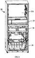
- FIG. 1 is a schematic partial structural view of a refrigerating and freezing apparatus according to an embodiment of the present invention.
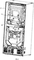
- FIG. 2 is a schematic partial structural view of the structure shown in FIG. 1 from another perspective.
- the embodiment of the present invention provides the refrigerating and freezing device, which may comprise a box body 20, a main door body, an air-conditioning membrane assembly 30, an air pump 41, and a refrigerating system.
- the box body 20 comprises a liner 21, a shell 27 disposed outside the liner 21, and a thermal insulation layer between the liner 21 and the shell 27.
- a storage space 211 is defined in the liner 21.
- the main door body can be formed by two opposite door bodies; and the two opposite door bodies can be rotatably mounted to the box body 20, and configured to open or close the storage space 211 defined by the box body 20.
- the main door body can also be one door body.
- a storage container is disposed in the storage space 211; and the storage container has an air-conditioning freshness-keeping space therein.
- the air-conditioning freshness-keeping space can be a closed space or an approximately closed space.
- the storage container is a drawer assembly.
- the storage container comprises a drawer cylinder 22 and a drawer body 23.
- the drawer cylinder 22 has forward opening and is disposed in the storage space 211, and can be disposed at the lower part of the storage space 211 specifically. As can be appreciated by those skilled in the art, the drawer cylinder 22 can also be disposed in the middle or upper part of the storage space 211.
- the drawer body 23 is slidably disposed in the drawer cylinder 22 to be operatively withdrawn from and inwardly inserted into the drawer cylinder 22 from the forward opening of the drawer cylinder 22.
- the drawer body 23 can have a drawer end cover which can cooperate with the opening of the drawer cylinder 22, so as to seal the air-conditioning freshness-keeping space.
- the storage container may comprise a cylinder and a small door body configured to open or close the cylinder.
- the refrigerating system is configured to provide cold to the storage space 211.
- the refrigerating system can be a refrigerating cycle system formed by a compressor, a condenser, a throttling device, an evaporator and the like.
- the evaporator is configured to provide the cold to the storage space 211 directly or indirectly.
- the refrigerating and freezing device is a household compression-type direct-cooling refrigerator; and the evaporator may be disposed outside or inside the rear wall surface of the liner 21.
- the box body 20 When the refrigerating and freezing device is a household compression-type air-cooled refrigerator, the box body 20 further has an evaporator chamber therein; and the evaporator chamber communicates with the storage space 211 by an air passage system.
- the evaporator is disposed in the evaporator chamber, and a fan is arranged at the outlet to perform cycle refrigeration on the storage space 211.
- the refrigerating system may also be a semiconductor refrigerating device.
- the air-conditioning membrane assembly 30 has at least one air-conditioning membrane 31 and an oxygen-rich gas collecting chamber.
- the surrounding space of the air-conditioning membrane assembly 30 communicates with the air-conditioning freshness-keeping space.
- the air-conditioning membrane assembly 30 is configured such that more oxygen in the airflow in the surrounding space of the air-conditioning membrane assembly 30 permeates through the air-conditioning membrane 31 to enter the oxygen-rich gas collecting chamber relative to the nitrogen in the airflow in the surrounding space of the air-conditioning membrane assembly 30.
- each air-conditioning membrane 31 faces the oxygen-rich gas collecting chamber, so that when the pressure of the oxygen-rich gas collecting chamber is lower than the pressure of the surrounding space of the air-conditioning membrane assembly 30, more oxygen in the air in the outer space of the air-conditioning membrane assembly 30 permeates through the at least one air-conditioning membrane 31 to enter the oxygen-rich gas collecting chamber relative to the nitrogen in the air.
- the air pump 41 may be disposed in the thermal insulation layer between the liner 21 and the shell 27, wherein the inlet end of the air pump 41 communicates with the oxygen-rich gas collecting chamber of the air-conditioning membrane assembly 30 via a pipeline to extract the gas permeating into the oxygen-rich gas collecting chamber to the outside of the storage container.
- the gas exhaust pipeline connected to the outlet of the air pump 41 may penetrate the thermal insulation layer to extend into an evaporating dish which may also be called a water receiving tray.
- the air pump 41 extracts the gas outwardly, so that the pressure of the oxygen-rich gas collecting chamber is lower than the pressure of the surrounding space of the air-conditioning membrane assembly 30. Further, the oxygen in the surrounding space of the air-conditioning membrane assembly 30 is enabled to enter the oxygen-rich gas collecting chamber. Since the air-conditioning freshness-keeping space communicates with the surrounding space of the air-conditioning membrane assembly 30, the air in the air-conditioning freshness-keeping space will enter the surrounding space of the air-conditioning membrane assembly 30. Therefore, the oxygen in the air in the air-conditioning freshness-keeping space is also enabled to enter the oxygen-rich gas collecting chamber, thereby obtaining the nitrogen-rich oxygen-poor atmosphere favorable for food freshness keeping in the air-conditioning freshness-keeping space.
- the nitrogen-rich oxygen-poor atmosphere favorable for food freshness keeping can be formed in the air-conditioning freshness-keeping space.
- the oxygen content in the space where the fruits and vegetables are preserved is reduced to reduce the intensity of aerobic respiration of the fruits and vegetables.
- a basic respiration function is ensured, thereby preventing anaerobic respiration of the fruits and vegetables, and further achieving the purpose of long-term freshness keeping of the fruits and vegetables.
- the atmosphere also has a large amount of gases such as nitrogen gas, so that the cooling efficiency of an article in the air-conditioning freshness-keeping space is not reduced, thereby effectively storing the fruits and vegetables.
- the refrigerating and freezing device according to the present invention solves the above technical problem that the technicians in the field of air-conditioning freshness keeping have been eager to solve but has not successfully solved.
- the refrigerating and freezing device according to the present invention is not only small in size but also low in noise, and is especially suitable for families and individuals.
- the air pump 41 is disposed in the thermal insulation layer to significantly reduce the noise during operation of the air pump, thereby providing a better silence experience to the user.
- a plurality of micropores may be formed in the drawer cylinder 22, and the storage space 211 communicates with the air-conditioning freshness-keeping space via the plurality of micropores which may be air pressure balancing holes.
- Each of the micropores may be a millimeter-level micropore.
- each of the micropores has a diameter of 0.1 mm to 3 mm, preferably 1 mm, 1.5 mm, or the like. With the plurality of micropores, the pressure in the air-conditioning freshness-keeping space is not too low.
- the nitrogen in the air-conditioning freshness-keeping space will not flow to the large storage space 211; even if the nitrogen flows, the flow is very small or even negligible, which will not adversely affect the freshness keeping of food in the air-conditioning freshness-keeping space.
- the micropores may not be disposed in the drawer cylinder 22. Even so, a large amount of gases such as nitrogen still exists in the air-conditioning freshness-keeping space. The user can open the drawer body 23 without too much effort, and a lot of effort will be saved compared to the existing vacuum storage room.
- the liner 21 may be a refrigerating chamber liner.
- the storage space 211 is a refrigerating space, and the storage temperature thereof ranges from 2 °C to 10 °C, preferably between 3 °C and 8 °C.
- the box body 20 may also define a freezing space 25 and a temperature-changing space 26. That is, the box body 20 may further comprise a freezing chamber liner and a temperature-changing chamber liner.
- the freezing space 25 is disposed below the storage space 211, and the temperature-changing space 26 is disposed between the freezing space and the refrigerating space.
- the temperature range in the freezing space is generally -14 °C to -22 °C.
- the temperature-changing space can be adjusted as needed to store appropriate food.
- the storage space 211 may also be the freezing space or the temperature-changing space. That is, the temperature range of the storage space 211 may be controlled at -14 °C to -22 °C or adjusted as needed. Further, the relative positions of the refrigerating space, the freezing space, and the temperature-changing space may be adjusted according to actual needs.
- the shell 27 may comprise a back plate.
- the air pump 41 is disposed between the back wall of the liner 21 and the back plate and is located behind the storage container, so as to reduce the length of the pipeline between the air pump 41 and the air-conditioning membrane assembly 30, thereby reducing the vacuum loss in air conditioning.
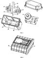
- FIG. 3 is a schematic exploded view of an air pump assembly 40 in a refrigerating and freezing device according to an embodiment of the present invention.
- the refrigerating and freezing device may further comprise a sealing box 43 and a mounting frame 44.
- the mounting frame 44 and the inner wall of the sealing box 43 are connected by a plurality of damping cushion blocks.
- the air pump 41 is fixed inside the mounting frame 44, so as to reduce the vibration and noise during operation of the air pump 41.
- the bottom of the mounting frame 44 is provided with two damping cushion blocks 45; and the damping cushion blocks 45 sleeve positioning posts 46 on the bottom surface of the sealing box 43.
- One circular damping cushion block 47 is disposed on each of the two opposite sides of the mounting frame 44, and is clamped in a corresponding clamping groove 48 of the sealing box 43.
- One damping cushion block 49 is fixed on each of the other two opposite sides of the mounting frame 44.
- the air pump 41 may be placed among the various damping cushion blocks in the sealing box 43 and fastened to the mounting frame by screws.
- the thermal insulation layer is further internally provided with a pump component mounting chamber partitioned by a partition plate, the rear wall of the liner 21 and the like; and the sealing box 43 may be disposed in the pump component mounting chamber by a damping component.
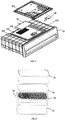
- the air-conditioning membrane assembly 30 may be disposed on the cylinder wall of the drawer cylinder 22. Further, the air-conditioning membrane assembly 30 may be in the form of a flat plate, and preferably disposed on the top wall of the drawer cylinder 22 horizontally. Specifically, an accommodating chamber 221 is disposed in the top wall of the drawer cylinder 22 to accommodate the air-conditioning membrane assembly 30. At least one first vent hole 222 and a second vent hole 223 are formed in a wall surface between the accommodating chamber of the top wall of the drawer cylinder 22 and the air-conditioning freshness-keeping space.
- the at least one first vent hole 222 is spaced apart from the at least one second vent hole 223, so as to communicate the accommodating chamber with the air-conditioning freshness-keeping space at different positions. There may be multiple first vent holes 222 and the second vent holes 223 which are small holes.
- the inner side of the top wall of the drawer cylinder 22 has a sunken groove.
- the air-conditioning membrane assembly 30 is disposed in the sunken groove of the top wall of the drawer cylinder 22.
- the refrigerating and freezing device may further comprise a fan 60, which may be disposed in the accommodating chamber.
- the fan is configured to promote the gas in the air-conditioning freshness-keeping space to enter the accommodating chamber 221 via the first vent hole 222, and cause the gas in the accommodating chamber 221 to enter the air-conditioning freshness-keeping space via the second vent hole 223. That is, the fan 60 can promote the gas in the air-conditioning freshness-keeping space to be returned to the air-conditioning freshness-keeping space via the at least one first vent hole 222, the accommodating chamber, and the at least one second vent hole 223 in sequence.
- the fan 60 is preferably a centrifugal fan and disposed at the first vent hole 222 of the accommodating chamber 221. That is, the centrifugal fan is located above the at least one first vent hole 222, and has an axis of rotation vertically downward and an air inlet opening directly facing the first vent hole 222. The air outlet of the centrifugal fan may face the air-conditioning membrane assembly 30.
- the air-conditioning membrane assembly 30 is disposed above the at least one second vent hole 223, such that each air-conditioning membrane of the air-conditioning membrane assembly 30 is parallel to the top wall of the drawer cylinder 22.
- the at least one first vent hole 222 is disposed in the front part of the top wall, and the at least one second vent hole 223 is disposed in the rear part of the top wall.
- the centrifugal fan is disposed at the front part of the accommodating chamber 221
- the air-conditioning membrane assembly 30 is disposed at the rear part of the accommodating chamber 221
- the air-conditioning membrane assembly 30 is disposed behind the centrifugal fan.
- the top wall of the drawer cylinder 22 comprises a main plate portion 224 and a cover plate portion 225.
- a sunken portion is formed in a local region of the main plate portion 224.
- the cover plate portion 26 is detachably disposed on the recessed portion in a covering manner, so as to form the accommodating chamber 221.
- the main plate portion 224 may be integrally formed with the side wall, the bottom wall, and the rear wall of the drawer cylinder 22.
- the air-conditioning membrane assembly 30 can be in the shape of a flat plate, the air-conditioning membrane assembly 30 can also comprise a support frame 32.
- the air-conditioning membrane 31 is an oxygen-enriching membrane preferably and two air-conditioning membranes 31 can be disposed and mounted on both sides of the support frame 32, so that the two air-conditioning membranes 31 and the support frame 32 define the oxygen-rich gas collecting chamber together.
- the support frame 32 may comprise a side frame; and structures such as rib plates and/or flat plates and other structures are disposed in the frame.
- Airflow channels may be formed between the rib plates and between the rib plates and the flat plates, and the surfaces of the rib plates and the surfaces of the flat plates may be provided with grooves for forming the airflow channels.
- the rib plates and/or the flat plates can increase the structural strength and the like of the air-conditioning membrane assembly 30. That is, the support frame 32 has a first surface and a second surface parallel to each other. The support frame 32 is provided with the plurality of airflow channels extending on the first surface and the second surface respectively, and penetrating the support frame 32 to communicate the first surface and the second surface. The plurality of airflow channels forms the oxygen-rich gas collecting chamber together.
- the at least one air-conditioning membrane 31 is two planar air-conditioning membranes which are paved on the first surface and the second surface of the support frame 32 respectively.
- the support frame 32 comprises an air extracting hole 33 communicating with the at least one airflow channel and disposed in the side frame, so that the oxygen in the oxygen-rich gas collecting chamber is allowed to be output.
- the air extracting hole 33 communicates with the air pump 41.
- the air extracting hole 33 may be disposed in the long side of the side frame or in the short side of the frame, which is determined according to the set orientation of the air-conditioning membrane assembly 30 or actual design requirements.
- the air extracting hole 33 may be disposed in the long side of the side frame.
- the air-conditioning membrane 31 is firstly mounted on the side frame by a double-sided tape 34, and then sealed by a sealant 35.
- the support frame 32 may comprise a side frame, a plurality of first rib plates, and a plurality of second rib plates.
- the above plurality of first rib plates is longitudinally disposed inside the side frame at an interval and transversely extends; and one side surfaces of the plurality of first rib plates form a first surface.
- the plurality of second rib plates is transversely disposed at an interval and longitudinally extends on the other side surface of the plurality of first rib plates, and one side surfaces of the above plurality of second rib plates away from the first rib plates form a second surface.
- the plurality of first rib plates longitudinally disposed at an interval and transversely extending and the plurality of second rib plates transversely disposed at an interval on one side surface of the plurality of first rib plates and longitudinally extending are disposed inside the frame, so that the continuity of the airflow channels is ensured on one hand, the size of the support frame 32 is greatly reduced on the other hand, and the strength of the support frame 32 is greatly enhanced.
- the above structure of the support frame 32 ensures that the air-conditioning membrane 31 can obtain sufficient support, and can maintain better flatness all the time even when the negative pressure inside the oxygen-rich gas collecting chamber is relatively higher. Thus, the long service life of the air-conditioning membrane assembly 30 is ensured.
- the plurality of first rib plates may comprise a plurality of first narrow rib plates and a plurality of first wide rib plates.
- the plurality of first wide rib plates is disposed at an interval, and the plurality of first narrow rib plates is disposed between every two adjacent first wide rib plates.
- the above plurality of second rib plates may comprise a plurality of second narrow rib plates and a plurality of second wide rib plates.
- the plurality of second wide rib plates is disposed at an interval, and the plurality of the second narrow rib plates is disposed between every two adjacent second wide rib plates.
- each first wide rib plate is sunk inwardly from a side surface thereof on which the first surface is formed to form a first trench.
- Each second wide rib plate is sunk inwardly from a side surface thereof on which the second surface is formed to form a second trench, thereby improving the communication of the internal grid structure under the premise of ensuring that the thickness of the support frame 32 is very small (or the size is very small).
- a partial surface of each first wide rib plate deviated away from the first surface extends toward the second rib plate to be flush with the second surface.
- the first wide rib plate is sunk inwardly from the partial surface which is flush with the second surface to form a third trench.
- the intersecting parts the third trench and the second trench are communicated to form a cross trench.
- a partial surface of the at least one of the plurality of second wide rib plates deviated away from the second surface extends toward the first rib plate to be flush with the first surface.
- At least one of the plurality of second wide rib plates is inwardly sunk from and the partial surface which is flush with the first surface to form a fourth trench.
- the intersecting parts of the fourth trench and the first trench are communicated to form a cross groove.
- the inner surface of the cover plate portion 225 may extend downwardly to form a plurality of air guiding rib plates, so as to guide the airflow from the fan 60 to flow through the outside surface of each air-conditioning membrane 31 of the air-conditioning membrane assembly 30 deviated away from the oxygen-rich gas collecting chamber in the accommodating chamber.
- the plurality of air guiding rib plates may be divided into two groups, comprising a first group of air guiding rib plates and a second group of air guiding rib plates which are symmetrically disposed with the first group of air guiding rib plates about a plane.
- Each group of air guiding rib plates comprises a first air guiding rib plate, at least one second air guiding rib plate, and at least one third air guiding rib plate.
- the first air guiding rib extends from the air outlet of the centrifugal fan to one side of the accommodating chamber and extends to a transverse outer side of the air-conditioning membrane assembly 30.
- Each second air guiding rib plate is disposed between the two first air guiding rib plates and between the air-conditioning membrane assembly 30 and the centrifugal fan.
- Each third air guiding rib plate is located on a transverse outer side of the air-conditioning membrane assembly 30.
- a locking device, a handle and a handle positioning device are disposed between the drawer body 23 and the drawer cylinder 22.
- the locking device comprises pivoting lock catches disposed on both sides of the end cover of the drawer, two buckling portions disposed on the drawer cylinder 22, and a fastening promoting device.
- Each buckling portion may be a protrusion.
- the fastening promoting device may be configured to promote the two pivoting lock catches to rotate in the directions (i.e., their respective first directions) to be engaged with their respective buckling portions.
- the handle extends horizontally and may be slidably mounted to the end cover of the drawer in a vertical direction.
- the position of the handle may be the initial position of the handle.
- the handle is configured such that both ends thereof are in contact with and abut against the two pivoting lock catches respectively when in the initial position, to prevent each pivoting lock catch from rotating in the other direction opposite to the corresponding first direction.
- the pivoting lock catches are engaged with the buckling portions to lock the drawer body 23 in the drawer cylinder 22.
- each pivoting lock catch is allowed to rotate in the direction opposite to the corresponding first direction when the handle is moved vertically to the locking releasing position, i.e., from the initial position to the locking releasing position.
- the pivoting lock catches are allowed to rotate to be disengaged from the corresponding buckling portions when the drawer body 23 is pulled outwardly, thereby opening the drawer body 23.
- the handle positioning device is configured to hold the handle in the predetermined position after the handle is moved to each predetermined position, primarily comprising the initial position and the locking releasing position.
- the handle positioning device holds the handle in such position, and then the user pulls the drawer body 23 outwardly.
- the user When the drawer body is required to be closed, the user firstly closes the drawer body 23 and then returns the handle to the initial position by moving it vertically, and the handle positioning device holds the handle in such position, thereby holding the drawer body 23 and the drawer cylinder 22 in a locked state.
- the two ends of the handle are respectively provided with a guiding rod and a sliding block; and the guiding rod extends in the vertical direction.
- the drawer body 23 further comprises two groups of slideways; and each group of the slideways at least has three chutes extending in the vertical direction, so that two chutes are located at the both sides of the guide bar respectively, and the sliding block moves on the remaining chute; or two chutes are located at the both sides of the sliding block respectively, and the guiding rod moves on the remaining chute.
- each group of the slideways may comprise four chutes, wherein two chutes are located at the front and rear sides of the guiding rod respectively, and two chutes are located at the transverse two sides (i.e., the left and right sides) of the sliding block respectively.
Landscapes
- Engineering & Computer Science (AREA)
- Chemical & Material Sciences (AREA)
- Combustion & Propulsion (AREA)
- Physics & Mathematics (AREA)
- Mechanical Engineering (AREA)
- Thermal Sciences (AREA)
- General Engineering & Computer Science (AREA)
- Analytical Chemistry (AREA)
- General Chemical & Material Sciences (AREA)
- Oil, Petroleum & Natural Gas (AREA)
- Chemical Kinetics & Catalysis (AREA)
- Organic Chemistry (AREA)
- Life Sciences & Earth Sciences (AREA)
- Inorganic Chemistry (AREA)
- Wood Science & Technology (AREA)
- Zoology (AREA)
- Food Science & Technology (AREA)
- Polymers & Plastics (AREA)
- Cold Air Circulating Systems And Constructional Details In Refrigerators (AREA)
Claims (7)
- Kühl- und Gefriervorrichtung, umfassend:einen Boxkörper (20), aufweisend eine Auskleidung (21), eine Hülle (27), die außerhalb der Auskleidung (21) angeordnet ist, und eine Wärmeisolierungsschicht, die sich zwischen der Auskleidung (21) und der Hülle (27) befindet, wobei ein Speicherraum (211) in der Auskleidung (21) definiert ist, ein Speicherbehälter im Speicherraum (211) angeordnet ist und der Speicherbehälter einen Klimaanlagen-Frischhalteraum darin aufweist;eine Klimaanlagen-Membrananordnung (30), aufweisend mindestens eine Klimaanlagen-Membran (31) und eine Kammer zum Ansammeln von sauerstoffreichem Gas, wobei ein Umgebungsraum der Klimaanlagen-Membrananordnung (30) mit dem Klimaanlagen-Frischhalteraum verbunden ist und die Klimaanlagen-Membrananordnung (30) derart konfiguriert ist, dass mehr Sauerstoff im Luftstrom im Umgebungsraum der Klimaanlagen-Membrananordnung (30) die Klimaanlagen-Membran (30) durchdringt, um in die Kammer zum Ansammeln von sauerstoffreichem Gas mit Bezug auf den Stickstoff im Luftstrom im Umgebungsraum der Klimaanlagen-Membrananordnung (30) einzudringen;eine Luftpumpe (41), die in der Wärmeisolierungsschicht zwischen der Auskleidung (21) und der Hülle (27) angeordnet ist, wobei das Einlassende der Luftpumpe (41) mit der Kammer zum Ansammeln von sauerstoffreichem Gas mit Hilfe einer Rohrleitung verbunden ist, um das Gas zu extrahieren, das in die Kammer zum Ansammeln von sauerstoffreichem Gas an die Außenseite der Speicherkammer dringt;dadurch gekennzeichnet, dassder Speicherbehälter eine Schiebeanordnung ist und Folgendes umfasst:einen Schiebezylinder (22), aufweisend eine nach vorne gerichtete Öffnung und angeordnet im Speicherraum (211); undeinen Schiebekörper (23), der gleitbar im Schiebezylinder (22) montiert ist, um in Betrieb von der nach vorne gerichteten Öffnung des Schiebezylinders (22) nach außen vom Schiebezylinder zurückgezogen und nach innen in den Schiebezylinder (22) eingeführt zu werden, wobei eine Aufnahmekammer (221), die mit dem Klimaanlagen-Frischhalteraum verbunden ist, in einer oberen Wand des Schiebezylinders (22) angeordnet ist, um die Klimaanlagen-Membrananordnung (30) aufzunehmen;wobeimindestens ein erstes Entlüftungsloch (222) und mindestens ein zweites Entlüftungsloch (223), das vom mindestens einen ersten Entlüftungsloch (222) beabstandet ist, in einer Wandfläche zwischen der Aufnahmekammer (221) der oberen Wand des Schiebezylinders (22) und dem Klimaanlagen-Frischhalteraum gebildet sind, um die Aufnahmekammer (221) mit dem Klimaanlagen-Frischhalteraum an verschiedenen Positionen zu verbinden, und wobei die Kühl- und Gefriervorrichtung weiter eine Gebläse (60) umfasst, das in der Aufnahmekammer (221) angeordnet ist, um zu veranlassen, dass das Gas im Klimaanlagen-Frischhalteraum an den Klimaanlagen-Frischhalteraum mit Hilfe des mindestens einen ersten Entlüftungslochs (222), der Aufnahmekammer (221) und dem mindestens zweiten Entlüftungsloch (223) in Aufeinanderfolge zurückgeführt wird.
- Kühl- und Gefriervorrichtung nach Anspruch 1, wobei die Hülle (27) eine hintere Platte umfasst und die Luftpumpe (41) zwischen der hinteren Wand der Auskleidung (21) und der hinteren Platte angeordnet ist und sich hinter dem Speicherbehälter befindet.
- Kühl- und Gefriervorrichtung nach Anspruch 1, weiter umfassend:eine Dichtbox (43), die zwischen der Auskleidung (21) und der Hülle (27) montiert ist; undeinen Montagerahmen (44), der in der Dichtbox (43) mit Hilfe einer Vielzahl von Dämpfungskissenblöcken (45) montiert ist, wobei die Luftpumpe (41) auf dem Montagerahmen (44) montiert ist.
- Kühl- und Gefriervorrichtung nach Anspruch 1, wobei das Gebläse (60) ein Radialgebläse (60) ist und sich über dem mindestens einen ersten Entlüftungsloch (222) befindet, eine Drehachse des Radialgebläses (60) vertikal nach unten zeigt und ein Lufteinlass des Radialgebläses (60) dem mindestens einen ersten Entlüftungsloch (222) gegenüber liegt; und die Klimaanlagen-Membrananordnung (30) über dem mindestens einen zweiten Entlüftungsloch (223) angeordnet ist, so dass jede der Klimaanlagen-Membrane (31) der Klimaanlagen-Membrananordnung (30) parallel zur oberen Wand ist.
- Kühl- und Gefriervorrichtung nach Anspruch 4, wobei das Radialgebläse (60) an der Vorderseite der Aufnahmekammer (221) angeordnet ist und die Klimaanlagen-Membrananordnung (30) hinter dem Radialgebläse (60) angeordnet ist.
- Kühl- und Gefriervorrichtung nach Anspruch 1, wobei die Klimaanlagen-Membrananordnung (30) weiter einen Stützrahmen (32) umfasst, aufweisend eine erste Fläche und eine zweite Fläche, die parallel zueinander sind, der Stützrahmen (32) mit einer Vielzahl von Luftströmungskanälen ausgestattet ist, die sich auf der ersten Fläche bzw. der zweiten Fläche erstrecken und in den Stützrahmen (32) eindringen, um die erste Fläche mit der zweiten Fläche zu verbinden, und die Vielzahl von Luftströmungskanälen zusammen die Kammer zum Ansammeln von sauerstoffreichem Gas bilden; und mindestens eine Klimaanlagen-Membran (31) zwei planare Klimaanlagen-Membrane (31) umfasst, die auf der ersten Fläche bzw. der zweiten Fläche des Stützrahmens (32) befestigt sind.
- Kühl- und Gefriervorrichtung nach Anspruch 1, wobei der Speicherraum (211) ein Kühlraum ist, und wobei der Boxkörper (20) weiter einen Kühlraum (25) und einen Temperatur-Änderungsraum (26) definiert, wobei der Kühlraum (25) unter dem Speicherraum (211) angeordnet ist und der Temperatur-Änderungsraum (26) zwischen dem Gefrierraum (25) und dem Kühlraum angeordnet ist.
Applications Claiming Priority (2)
| Application Number | Priority Date | Filing Date | Title |
|---|---|---|---|
| CN201611132067.6A CN106546053B (zh) | 2016-12-09 | 2016-12-09 | 冷藏冷冻装置 |
| PCT/CN2017/115124 WO2018103720A1 (zh) | 2016-12-09 | 2017-12-08 | 冷藏冷冻装置 |
Publications (3)
| Publication Number | Publication Date |
|---|---|
| EP3553432A1 EP3553432A1 (de) | 2019-10-16 |
| EP3553432A4 EP3553432A4 (de) | 2019-11-27 |
| EP3553432B1 true EP3553432B1 (de) | 2021-01-20 |
Family
ID=58396962
Family Applications (1)
| Application Number | Title | Priority Date | Filing Date |
|---|---|---|---|
| EP17878073.0A Active EP3553432B1 (de) | 2016-12-09 | 2017-12-08 | Kühl- und gefriervorrichtung |
Country Status (6)
| Country | Link |
|---|---|
| US (1) | US11280537B2 (de) |
| EP (1) | EP3553432B1 (de) |
| CN (1) | CN106546053B (de) |
| AU (1) | AU2017373235B2 (de) |
| RU (1) | RU2721246C1 (de) |
| WO (1) | WO2018103720A1 (de) |
Cited By (1)
| Publication number | Priority date | Publication date | Assignee | Title |
|---|---|---|---|---|
| US20210025638A1 (en) * | 2017-12-11 | 2021-01-28 | Qingdao Haier Co., Ltd. | Refrigerator |
Families Citing this family (8)
| Publication number | Priority date | Publication date | Assignee | Title |
|---|---|---|---|---|
| CN106546053B (zh) * | 2016-12-09 | 2019-12-06 | 青岛海尔股份有限公司 | 冷藏冷冻装置 |
| CN108302862A (zh) * | 2017-12-29 | 2018-07-20 | 青岛海尔股份有限公司 | 冷藏冷冻装置 |
| CN108759244A (zh) * | 2018-06-19 | 2018-11-06 | 青岛海尔股份有限公司 | 具有控氧保鲜功能的冰箱 |
| CN108759243A (zh) * | 2018-06-19 | 2018-11-06 | 青岛海尔股份有限公司 | 控氧保鲜冰箱 |
| CN111473565B (zh) * | 2019-01-23 | 2022-11-18 | 青岛海尔电冰箱有限公司 | 冷藏冷冻装置 |
| CN111473569B (zh) * | 2019-01-23 | 2025-02-18 | 青岛海尔电冰箱有限公司 | 冷藏冷冻装置 |
| CN112824788A (zh) * | 2019-11-21 | 2021-05-21 | 青岛海尔电冰箱有限公司 | 冰箱 |
| CN113639507B (zh) * | 2021-07-19 | 2022-11-22 | 重庆海尔制冷电器有限公司 | 冷藏冷冻设备 |
Family Cites Families (12)
| Publication number | Priority date | Publication date | Assignee | Title |
|---|---|---|---|---|
| JPH05227881A (ja) * | 1992-02-19 | 1993-09-07 | Matsushita Refrig Co Ltd | 保存庫 |
| JPH0618152A (ja) * | 1992-07-03 | 1994-01-25 | Toshiba Corp | 冷蔵庫 |
| JP2004093026A (ja) * | 2002-08-30 | 2004-03-25 | Toshiba Corp | 冷蔵庫 |
| JP2004360948A (ja) * | 2003-06-03 | 2004-12-24 | Sanyo Electric Co Ltd | 冷蔵庫 |
| CN2697545Y (zh) * | 2004-04-05 | 2005-05-04 | 声宝股份有限公司 | 改良的冰箱保鲜结构 |
| ITTO20040623A1 (it) * | 2004-09-16 | 2004-12-16 | Merloni Elettrodomestici Spa | Apparato di refrigerazione e per la creazione combinata del vuoto |
| CN201199115Y (zh) * | 2008-04-10 | 2009-02-25 | 河南新飞电器有限公司 | 一种降氧气调保鲜冰箱 |
| CN101766321B (zh) * | 2008-12-30 | 2012-10-24 | 苏州三星电子有限公司 | 超长期保鲜系统 |
| KR101572716B1 (ko) * | 2012-06-29 | 2015-11-27 | 가부시끼가이샤 도시바 | 냉장고 및 산소 저감 장치 |
| JP5971296B2 (ja) * | 2014-09-16 | 2016-08-17 | ダイキン工業株式会社 | コンテナ用冷凍装置 |
| CN206449966U (zh) * | 2016-12-09 | 2017-08-29 | 青岛海尔股份有限公司 | 冷藏冷冻装置 |
| CN106546053B (zh) * | 2016-12-09 | 2019-12-06 | 青岛海尔股份有限公司 | 冷藏冷冻装置 |
-
2016
- 2016-12-09 CN CN201611132067.6A patent/CN106546053B/zh active Active
-
2017
- 2017-12-08 WO PCT/CN2017/115124 patent/WO2018103720A1/zh not_active Ceased
- 2017-12-08 RU RU2019116974A patent/RU2721246C1/ru active
- 2017-12-08 AU AU2017373235A patent/AU2017373235B2/en active Active
- 2017-12-08 EP EP17878073.0A patent/EP3553432B1/de active Active
- 2017-12-08 US US16/468,278 patent/US11280537B2/en active Active
Non-Patent Citations (1)
| Title |
|---|
| None * |
Cited By (2)
| Publication number | Priority date | Publication date | Assignee | Title |
|---|---|---|---|---|
| US20210025638A1 (en) * | 2017-12-11 | 2021-01-28 | Qingdao Haier Co., Ltd. | Refrigerator |
| US11668510B2 (en) * | 2017-12-11 | 2023-06-06 | Qingdao Haier Co., Ltd. | Refrigerator |
Also Published As
| Publication number | Publication date |
|---|---|
| AU2017373235A1 (en) | 2019-06-13 |
| CN106546053B (zh) | 2019-12-06 |
| AU2017373235B2 (en) | 2020-04-09 |
| CN106546053A (zh) | 2017-03-29 |
| EP3553432A4 (de) | 2019-11-27 |
| NZ753843A (en) | 2020-12-18 |
| EP3553432A1 (de) | 2019-10-16 |
| RU2721246C1 (ru) | 2020-05-18 |
| US11280537B2 (en) | 2022-03-22 |
| US20200072529A1 (en) | 2020-03-05 |
| WO2018103720A1 (zh) | 2018-06-14 |
Similar Documents
| Publication | Publication Date | Title |
|---|---|---|
| EP3553432B1 (de) | Kühl- und gefriervorrichtung | |
| AU2017369118B2 (en) | Air-regulating freshness-preserving food storage device | |
| CN106839586B (zh) | 冷藏冷冻装置 | |
| US10982895B2 (en) | Refrigerating and freezing device | |
| WO2018103721A1 (zh) | 冷藏冷冻装置 | |
| EP3550228B1 (de) | Kühl- und gefriervorrichtung | |
| CN106546054B (zh) | 冷藏冷冻装置 | |
| CN106839584B (zh) | 风冷冰箱 | |
| CN106679278B (zh) | 冷藏冷冻装置 | |
| CN206449967U (zh) | 冷藏冷冻装置 | |
| CN106642916A (zh) | 冷藏冷冻装置 | |
| CN206449966U (zh) | 冷藏冷冻装置 | |
| CN206291612U (zh) | 抽屉组件及具有该抽屉组件的冷藏冷冻装置 | |
| NZ753843B2 (en) | Refrigerating and freezing device | |
| CN206291581U (zh) | 冷藏冷冻装置 | |
| CN206291582U (zh) | 冷藏冷冻装置 | |
| NZ753844B2 (en) | Refrigeration and freezing device | |
| CN106642918A (zh) | 冷藏冷冻装置 | |
| NZ753838B2 (en) | Air-regulating freshness-preserving food storage device |
Legal Events
| Date | Code | Title | Description |
|---|---|---|---|
| STAA | Information on the status of an ep patent application or granted ep patent |
Free format text: STATUS: THE INTERNATIONAL PUBLICATION HAS BEEN MADE |
|
| PUAI | Public reference made under article 153(3) epc to a published international application that has entered the european phase |
Free format text: ORIGINAL CODE: 0009012 |
|
| STAA | Information on the status of an ep patent application or granted ep patent |
Free format text: STATUS: REQUEST FOR EXAMINATION WAS MADE |
|
| 17P | Request for examination filed |
Effective date: 20190603 |
|
| AK | Designated contracting states |
Kind code of ref document: A1 Designated state(s): AL AT BE BG CH CY CZ DE DK EE ES FI FR GB GR HR HU IE IS IT LI LT LU LV MC MK MT NL NO PL PT RO RS SE SI SK SM TR |
|
| AX | Request for extension of the european patent |
Extension state: BA ME |
|
| A4 | Supplementary search report drawn up and despatched |
Effective date: 20191028 |
|
| RIC1 | Information provided on ipc code assigned before grant |
Ipc: F25D 25/02 20060101AFI20191022BHEP Ipc: F25D 17/06 20060101ALI20191022BHEP Ipc: C01B 13/02 20060101ALN20191022BHEP Ipc: F25D 11/02 20060101ALI20191022BHEP Ipc: B01D 53/22 20060101ALN20191022BHEP |
|
| DAV | Request for validation of the european patent (deleted) | ||
| DAX | Request for extension of the european patent (deleted) | ||
| RIC1 | Information provided on ipc code assigned before grant |
Ipc: F25D 11/02 20060101ALI20200825BHEP Ipc: F25D 25/02 20060101AFI20200825BHEP Ipc: C01B 13/02 20060101ALN20200825BHEP Ipc: F25D 17/06 20060101ALI20200825BHEP Ipc: B01D 53/22 20060101ALN20200825BHEP |
|
| GRAP | Despatch of communication of intention to grant a patent |
Free format text: ORIGINAL CODE: EPIDOSNIGR1 |
|
| STAA | Information on the status of an ep patent application or granted ep patent |
Free format text: STATUS: GRANT OF PATENT IS INTENDED |
|
| INTG | Intention to grant announced |
Effective date: 20201006 |
|
| GRAS | Grant fee paid |
Free format text: ORIGINAL CODE: EPIDOSNIGR3 |
|
| GRAA | (expected) grant |
Free format text: ORIGINAL CODE: 0009210 |
|
| STAA | Information on the status of an ep patent application or granted ep patent |
Free format text: STATUS: THE PATENT HAS BEEN GRANTED |
|
| AK | Designated contracting states |
Kind code of ref document: B1 Designated state(s): AL AT BE BG CH CY CZ DE DK EE ES FI FR GB GR HR HU IE IS IT LI LT LU LV MC MK MT NL NO PL PT RO RS SE SI SK SM TR |
|
| REG | Reference to a national code |
Ref country code: GB Ref legal event code: FG4D |
|
| REG | Reference to a national code |
Ref country code: CH Ref legal event code: EP |
|
| REG | Reference to a national code |
Ref country code: DE Ref legal event code: R096 Ref document number: 602017031891 Country of ref document: DE |
|
| REG | Reference to a national code |
Ref country code: AT Ref legal event code: REF Ref document number: 1356765 Country of ref document: AT Kind code of ref document: T Effective date: 20210215 |
|
| REG | Reference to a national code |
Ref country code: IE Ref legal event code: FG4D |
|
| REG | Reference to a national code |
Ref country code: NL Ref legal event code: MP Effective date: 20210120 |
|
| REG | Reference to a national code |
Ref country code: LT Ref legal event code: MG9D |
|
| REG | Reference to a national code |
Ref country code: AT Ref legal event code: MK05 Ref document number: 1356765 Country of ref document: AT Kind code of ref document: T Effective date: 20210120 |
|
| PG25 | Lapsed in a contracting state [announced via postgrant information from national office to epo] |
Ref country code: BG Free format text: LAPSE BECAUSE OF FAILURE TO SUBMIT A TRANSLATION OF THE DESCRIPTION OR TO PAY THE FEE WITHIN THE PRESCRIBED TIME-LIMIT Effective date: 20210420 Ref country code: LT Free format text: LAPSE BECAUSE OF FAILURE TO SUBMIT A TRANSLATION OF THE DESCRIPTION OR TO PAY THE FEE WITHIN THE PRESCRIBED TIME-LIMIT Effective date: 20210120 Ref country code: PT Free format text: LAPSE BECAUSE OF FAILURE TO SUBMIT A TRANSLATION OF THE DESCRIPTION OR TO PAY THE FEE WITHIN THE PRESCRIBED TIME-LIMIT Effective date: 20210520 Ref country code: NO Free format text: LAPSE BECAUSE OF FAILURE TO SUBMIT A TRANSLATION OF THE DESCRIPTION OR TO PAY THE FEE WITHIN THE PRESCRIBED TIME-LIMIT Effective date: 20210420 Ref country code: GR Free format text: LAPSE BECAUSE OF FAILURE TO SUBMIT A TRANSLATION OF THE DESCRIPTION OR TO PAY THE FEE WITHIN THE PRESCRIBED TIME-LIMIT Effective date: 20210421 Ref country code: HR Free format text: LAPSE BECAUSE OF FAILURE TO SUBMIT A TRANSLATION OF THE DESCRIPTION OR TO PAY THE FEE WITHIN THE PRESCRIBED TIME-LIMIT Effective date: 20210120 Ref country code: FI Free format text: LAPSE BECAUSE OF FAILURE TO SUBMIT A TRANSLATION OF THE DESCRIPTION OR TO PAY THE FEE WITHIN THE PRESCRIBED TIME-LIMIT Effective date: 20210120 |
|
| PG25 | Lapsed in a contracting state [announced via postgrant information from national office to epo] |
Ref country code: AT Free format text: LAPSE BECAUSE OF FAILURE TO SUBMIT A TRANSLATION OF THE DESCRIPTION OR TO PAY THE FEE WITHIN THE PRESCRIBED TIME-LIMIT Effective date: 20210120 Ref country code: LV Free format text: LAPSE BECAUSE OF FAILURE TO SUBMIT A TRANSLATION OF THE DESCRIPTION OR TO PAY THE FEE WITHIN THE PRESCRIBED TIME-LIMIT Effective date: 20210120 Ref country code: RS Free format text: LAPSE BECAUSE OF FAILURE TO SUBMIT A TRANSLATION OF THE DESCRIPTION OR TO PAY THE FEE WITHIN THE PRESCRIBED TIME-LIMIT Effective date: 20210120 Ref country code: PL Free format text: LAPSE BECAUSE OF FAILURE TO SUBMIT A TRANSLATION OF THE DESCRIPTION OR TO PAY THE FEE WITHIN THE PRESCRIBED TIME-LIMIT Effective date: 20210120 Ref country code: SE Free format text: LAPSE BECAUSE OF FAILURE TO SUBMIT A TRANSLATION OF THE DESCRIPTION OR TO PAY THE FEE WITHIN THE PRESCRIBED TIME-LIMIT Effective date: 20210120 |
|
| PG25 | Lapsed in a contracting state [announced via postgrant information from national office to epo] |
Ref country code: IS Free format text: LAPSE BECAUSE OF FAILURE TO SUBMIT A TRANSLATION OF THE DESCRIPTION OR TO PAY THE FEE WITHIN THE PRESCRIBED TIME-LIMIT Effective date: 20210520 |
|
| REG | Reference to a national code |
Ref country code: DE Ref legal event code: R097 Ref document number: 602017031891 Country of ref document: DE |
|
| PG25 | Lapsed in a contracting state [announced via postgrant information from national office to epo] |
Ref country code: EE Free format text: LAPSE BECAUSE OF FAILURE TO SUBMIT A TRANSLATION OF THE DESCRIPTION OR TO PAY THE FEE WITHIN THE PRESCRIBED TIME-LIMIT Effective date: 20210120 Ref country code: CZ Free format text: LAPSE BECAUSE OF FAILURE TO SUBMIT A TRANSLATION OF THE DESCRIPTION OR TO PAY THE FEE WITHIN THE PRESCRIBED TIME-LIMIT Effective date: 20210120 Ref country code: SM Free format text: LAPSE BECAUSE OF FAILURE TO SUBMIT A TRANSLATION OF THE DESCRIPTION OR TO PAY THE FEE WITHIN THE PRESCRIBED TIME-LIMIT Effective date: 20210120 |
|
| PLBE | No opposition filed within time limit |
Free format text: ORIGINAL CODE: 0009261 |
|
| STAA | Information on the status of an ep patent application or granted ep patent |
Free format text: STATUS: NO OPPOSITION FILED WITHIN TIME LIMIT |
|
| PG25 | Lapsed in a contracting state [announced via postgrant information from national office to epo] |
Ref country code: SK Free format text: LAPSE BECAUSE OF FAILURE TO SUBMIT A TRANSLATION OF THE DESCRIPTION OR TO PAY THE FEE WITHIN THE PRESCRIBED TIME-LIMIT Effective date: 20210120 Ref country code: DK Free format text: LAPSE BECAUSE OF FAILURE TO SUBMIT A TRANSLATION OF THE DESCRIPTION OR TO PAY THE FEE WITHIN THE PRESCRIBED TIME-LIMIT Effective date: 20210120 Ref country code: RO Free format text: LAPSE BECAUSE OF FAILURE TO SUBMIT A TRANSLATION OF THE DESCRIPTION OR TO PAY THE FEE WITHIN THE PRESCRIBED TIME-LIMIT Effective date: 20210120 |
|
| 26N | No opposition filed |
Effective date: 20211021 |
|
| PG25 | Lapsed in a contracting state [announced via postgrant information from national office to epo] |
Ref country code: ES Free format text: LAPSE BECAUSE OF FAILURE TO SUBMIT A TRANSLATION OF THE DESCRIPTION OR TO PAY THE FEE WITHIN THE PRESCRIBED TIME-LIMIT Effective date: 20210120 Ref country code: AL Free format text: LAPSE BECAUSE OF FAILURE TO SUBMIT A TRANSLATION OF THE DESCRIPTION OR TO PAY THE FEE WITHIN THE PRESCRIBED TIME-LIMIT Effective date: 20210120 |
|
| PG25 | Lapsed in a contracting state [announced via postgrant information from national office to epo] |
Ref country code: SI Free format text: LAPSE BECAUSE OF FAILURE TO SUBMIT A TRANSLATION OF THE DESCRIPTION OR TO PAY THE FEE WITHIN THE PRESCRIBED TIME-LIMIT Effective date: 20210120 |
|
| PG25 | Lapsed in a contracting state [announced via postgrant information from national office to epo] |
Ref country code: IT Free format text: LAPSE BECAUSE OF FAILURE TO SUBMIT A TRANSLATION OF THE DESCRIPTION OR TO PAY THE FEE WITHIN THE PRESCRIBED TIME-LIMIT Effective date: 20210120 |
|
| PG25 | Lapsed in a contracting state [announced via postgrant information from national office to epo] |
Ref country code: IS Free format text: LAPSE BECAUSE OF FAILURE TO SUBMIT A TRANSLATION OF THE DESCRIPTION OR TO PAY THE FEE WITHIN THE PRESCRIBED TIME-LIMIT Effective date: 20210520 |
|
| PG25 | Lapsed in a contracting state [announced via postgrant information from national office to epo] |
Ref country code: MC Free format text: LAPSE BECAUSE OF FAILURE TO SUBMIT A TRANSLATION OF THE DESCRIPTION OR TO PAY THE FEE WITHIN THE PRESCRIBED TIME-LIMIT Effective date: 20210120 |
|
| REG | Reference to a national code |
Ref country code: CH Ref legal event code: PL |
|
| REG | Reference to a national code |
Ref country code: BE Ref legal event code: MM Effective date: 20211231 |
|
| PG25 | Lapsed in a contracting state [announced via postgrant information from national office to epo] |
Ref country code: LU Free format text: LAPSE BECAUSE OF NON-PAYMENT OF DUE FEES Effective date: 20211208 Ref country code: IE Free format text: LAPSE BECAUSE OF NON-PAYMENT OF DUE FEES Effective date: 20211208 |
|
| PG25 | Lapsed in a contracting state [announced via postgrant information from national office to epo] |
Ref country code: BE Free format text: LAPSE BECAUSE OF NON-PAYMENT OF DUE FEES Effective date: 20211231 |
|
| PG25 | Lapsed in a contracting state [announced via postgrant information from national office to epo] |
Ref country code: LI Free format text: LAPSE BECAUSE OF NON-PAYMENT OF DUE FEES Effective date: 20211231 Ref country code: CH Free format text: LAPSE BECAUSE OF NON-PAYMENT OF DUE FEES Effective date: 20211231 |
|
| PG25 | Lapsed in a contracting state [announced via postgrant information from national office to epo] |
Ref country code: NL Free format text: LAPSE BECAUSE OF NON-PAYMENT OF DUE FEES Effective date: 20210120 Ref country code: CY Free format text: LAPSE BECAUSE OF FAILURE TO SUBMIT A TRANSLATION OF THE DESCRIPTION OR TO PAY THE FEE WITHIN THE PRESCRIBED TIME-LIMIT Effective date: 20210120 |
|
| PG25 | Lapsed in a contracting state [announced via postgrant information from national office to epo] |
Ref country code: HU Free format text: LAPSE BECAUSE OF FAILURE TO SUBMIT A TRANSLATION OF THE DESCRIPTION OR TO PAY THE FEE WITHIN THE PRESCRIBED TIME-LIMIT; INVALID AB INITIO Effective date: 20171208 |
|
| PG25 | Lapsed in a contracting state [announced via postgrant information from national office to epo] |
Ref country code: MK Free format text: LAPSE BECAUSE OF FAILURE TO SUBMIT A TRANSLATION OF THE DESCRIPTION OR TO PAY THE FEE WITHIN THE PRESCRIBED TIME-LIMIT Effective date: 20210120 |
|
| PG25 | Lapsed in a contracting state [announced via postgrant information from national office to epo] |
Ref country code: TR Free format text: LAPSE BECAUSE OF FAILURE TO SUBMIT A TRANSLATION OF THE DESCRIPTION OR TO PAY THE FEE WITHIN THE PRESCRIBED TIME-LIMIT Effective date: 20210120 |
|
| PG25 | Lapsed in a contracting state [announced via postgrant information from national office to epo] |
Ref country code: MT Free format text: LAPSE BECAUSE OF FAILURE TO SUBMIT A TRANSLATION OF THE DESCRIPTION OR TO PAY THE FEE WITHIN THE PRESCRIBED TIME-LIMIT Effective date: 20210120 |
|
| PGFP | Annual fee paid to national office [announced via postgrant information from national office to epo] |
Ref country code: DE Payment date: 20241211 Year of fee payment: 8 |
|
| PGFP | Annual fee paid to national office [announced via postgrant information from national office to epo] |
Ref country code: GB Payment date: 20251229 Year of fee payment: 9 |
|
| PGFP | Annual fee paid to national office [announced via postgrant information from national office to epo] |
Ref country code: FR Payment date: 20251230 Year of fee payment: 9 |