EP3553368A1 - Lighting device and lamp for automobile including same - Google Patents
Lighting device and lamp for automobile including same Download PDFInfo
- Publication number
- EP3553368A1 EP3553368A1 EP17877923.7A EP17877923A EP3553368A1 EP 3553368 A1 EP3553368 A1 EP 3553368A1 EP 17877923 A EP17877923 A EP 17877923A EP 3553368 A1 EP3553368 A1 EP 3553368A1
- Authority
- EP
- European Patent Office
- Prior art keywords
- light
- lighting device
- lens
- guide member
- light guide
- Prior art date
- Legal status (The legal status is an assumption and is not a legal conclusion. Google has not performed a legal analysis and makes no representation as to the accuracy of the status listed.)
- Granted
Links
Images



Classifications
-
- F—MECHANICAL ENGINEERING; LIGHTING; HEATING; WEAPONS; BLASTING
- F21—LIGHTING
- F21S—NON-PORTABLE LIGHTING DEVICES; SYSTEMS THEREOF; VEHICLE LIGHTING DEVICES SPECIALLY ADAPTED FOR VEHICLE EXTERIORS
- F21S41/00—Illuminating devices specially adapted for vehicle exteriors, e.g. headlamps
- F21S41/10—Illuminating devices specially adapted for vehicle exteriors, e.g. headlamps characterised by the light source
-
- F—MECHANICAL ENGINEERING; LIGHTING; HEATING; WEAPONS; BLASTING
- F21—LIGHTING
- F21S—NON-PORTABLE LIGHTING DEVICES; SYSTEMS THEREOF; VEHICLE LIGHTING DEVICES SPECIALLY ADAPTED FOR VEHICLE EXTERIORS
- F21S41/00—Illuminating devices specially adapted for vehicle exteriors, e.g. headlamps
- F21S41/20—Illuminating devices specially adapted for vehicle exteriors, e.g. headlamps characterised by refractors, transparent cover plates, light guides or filters
- F21S41/24—Light guides
-
- F—MECHANICAL ENGINEERING; LIGHTING; HEATING; WEAPONS; BLASTING
- F21—LIGHTING
- F21S—NON-PORTABLE LIGHTING DEVICES; SYSTEMS THEREOF; VEHICLE LIGHTING DEVICES SPECIALLY ADAPTED FOR VEHICLE EXTERIORS
- F21S10/00—Lighting devices or systems producing a varying lighting effect
- F21S10/005—Lighting devices or systems producing a varying lighting effect using light guides
-
- F—MECHANICAL ENGINEERING; LIGHTING; HEATING; WEAPONS; BLASTING
- F21—LIGHTING
- F21S—NON-PORTABLE LIGHTING DEVICES; SYSTEMS THEREOF; VEHICLE LIGHTING DEVICES SPECIALLY ADAPTED FOR VEHICLE EXTERIORS
- F21S4/00—Lighting devices or systems using a string or strip of light sources
- F21S4/20—Lighting devices or systems using a string or strip of light sources with light sources held by or within elongate supports
- F21S4/28—Lighting devices or systems using a string or strip of light sources with light sources held by or within elongate supports rigid, e.g. LED bars
-
- F—MECHANICAL ENGINEERING; LIGHTING; HEATING; WEAPONS; BLASTING
- F21—LIGHTING
- F21S—NON-PORTABLE LIGHTING DEVICES; SYSTEMS THEREOF; VEHICLE LIGHTING DEVICES SPECIALLY ADAPTED FOR VEHICLE EXTERIORS
- F21S43/00—Signalling devices specially adapted for vehicle exteriors, e.g. brake lamps, direction indicator lights or reversing lights
- F21S43/10—Signalling devices specially adapted for vehicle exteriors, e.g. brake lamps, direction indicator lights or reversing lights characterised by the light source
- F21S43/13—Signalling devices specially adapted for vehicle exteriors, e.g. brake lamps, direction indicator lights or reversing lights characterised by the light source characterised by the type of light source
- F21S43/14—Light emitting diodes [LED]
-
- F—MECHANICAL ENGINEERING; LIGHTING; HEATING; WEAPONS; BLASTING
- F21—LIGHTING
- F21S—NON-PORTABLE LIGHTING DEVICES; SYSTEMS THEREOF; VEHICLE LIGHTING DEVICES SPECIALLY ADAPTED FOR VEHICLE EXTERIORS
- F21S43/00—Signalling devices specially adapted for vehicle exteriors, e.g. brake lamps, direction indicator lights or reversing lights
- F21S43/20—Signalling devices specially adapted for vehicle exteriors, e.g. brake lamps, direction indicator lights or reversing lights characterised by refractors, transparent cover plates, light guides or filters
-
- F—MECHANICAL ENGINEERING; LIGHTING; HEATING; WEAPONS; BLASTING
- F21—LIGHTING
- F21S—NON-PORTABLE LIGHTING DEVICES; SYSTEMS THEREOF; VEHICLE LIGHTING DEVICES SPECIALLY ADAPTED FOR VEHICLE EXTERIORS
- F21S43/00—Signalling devices specially adapted for vehicle exteriors, e.g. brake lamps, direction indicator lights or reversing lights
- F21S43/20—Signalling devices specially adapted for vehicle exteriors, e.g. brake lamps, direction indicator lights or reversing lights characterised by refractors, transparent cover plates, light guides or filters
- F21S43/235—Light guides
- F21S43/236—Light guides characterised by the shape of the light guide
-
- F—MECHANICAL ENGINEERING; LIGHTING; HEATING; WEAPONS; BLASTING
- F21—LIGHTING
- F21S—NON-PORTABLE LIGHTING DEVICES; SYSTEMS THEREOF; VEHICLE LIGHTING DEVICES SPECIALLY ADAPTED FOR VEHICLE EXTERIORS
- F21S43/00—Signalling devices specially adapted for vehicle exteriors, e.g. brake lamps, direction indicator lights or reversing lights
- F21S43/20—Signalling devices specially adapted for vehicle exteriors, e.g. brake lamps, direction indicator lights or reversing lights characterised by refractors, transparent cover plates, light guides or filters
- F21S43/235—Light guides
- F21S43/236—Light guides characterised by the shape of the light guide
- F21S43/237—Light guides characterised by the shape of the light guide rod-shaped
-
- F—MECHANICAL ENGINEERING; LIGHTING; HEATING; WEAPONS; BLASTING
- F21—LIGHTING
- F21S—NON-PORTABLE LIGHTING DEVICES; SYSTEMS THEREOF; VEHICLE LIGHTING DEVICES SPECIALLY ADAPTED FOR VEHICLE EXTERIORS
- F21S43/00—Signalling devices specially adapted for vehicle exteriors, e.g. brake lamps, direction indicator lights or reversing lights
- F21S43/20—Signalling devices specially adapted for vehicle exteriors, e.g. brake lamps, direction indicator lights or reversing lights characterised by refractors, transparent cover plates, light guides or filters
- F21S43/235—Light guides
- F21S43/252—Two or more successive light guides
-
- F—MECHANICAL ENGINEERING; LIGHTING; HEATING; WEAPONS; BLASTING
- F21—LIGHTING
- F21S—NON-PORTABLE LIGHTING DEVICES; SYSTEMS THEREOF; VEHICLE LIGHTING DEVICES SPECIALLY ADAPTED FOR VEHICLE EXTERIORS
- F21S43/00—Signalling devices specially adapted for vehicle exteriors, e.g. brake lamps, direction indicator lights or reversing lights
- F21S43/20—Signalling devices specially adapted for vehicle exteriors, e.g. brake lamps, direction indicator lights or reversing lights characterised by refractors, transparent cover plates, light guides or filters
- F21S43/26—Refractors, transparent cover plates, light guides or filters not provided in groups F21S43/235 - F21S43/255
-
- F—MECHANICAL ENGINEERING; LIGHTING; HEATING; WEAPONS; BLASTING
- F21—LIGHTING
- F21S—NON-PORTABLE LIGHTING DEVICES; SYSTEMS THEREOF; VEHICLE LIGHTING DEVICES SPECIALLY ADAPTED FOR VEHICLE EXTERIORS
- F21S43/00—Signalling devices specially adapted for vehicle exteriors, e.g. brake lamps, direction indicator lights or reversing lights
- F21S43/20—Signalling devices specially adapted for vehicle exteriors, e.g. brake lamps, direction indicator lights or reversing lights characterised by refractors, transparent cover plates, light guides or filters
- F21S43/2605—Refractors
-
- F—MECHANICAL ENGINEERING; LIGHTING; HEATING; WEAPONS; BLASTING
- F21—LIGHTING
- F21S—NON-PORTABLE LIGHTING DEVICES; SYSTEMS THEREOF; VEHICLE LIGHTING DEVICES SPECIALLY ADAPTED FOR VEHICLE EXTERIORS
- F21S43/00—Signalling devices specially adapted for vehicle exteriors, e.g. brake lamps, direction indicator lights or reversing lights
- F21S43/30—Signalling devices specially adapted for vehicle exteriors, e.g. brake lamps, direction indicator lights or reversing lights characterised by reflectors
- F21S43/31—Optical layout thereof
-
- F—MECHANICAL ENGINEERING; LIGHTING; HEATING; WEAPONS; BLASTING
- F21—LIGHTING
- F21S—NON-PORTABLE LIGHTING DEVICES; SYSTEMS THEREOF; VEHICLE LIGHTING DEVICES SPECIALLY ADAPTED FOR VEHICLE EXTERIORS
- F21S43/00—Signalling devices specially adapted for vehicle exteriors, e.g. brake lamps, direction indicator lights or reversing lights
- F21S43/30—Signalling devices specially adapted for vehicle exteriors, e.g. brake lamps, direction indicator lights or reversing lights characterised by reflectors
- F21S43/33—Signalling devices specially adapted for vehicle exteriors, e.g. brake lamps, direction indicator lights or reversing lights characterised by reflectors characterised by their material, surface treatment or coatings
-
- G—PHYSICS
- G02—OPTICS
- G02B—OPTICAL ELEMENTS, SYSTEMS OR APPARATUS
- G02B6/00—Light guides; Structural details of arrangements comprising light guides and other optical elements, e.g. couplings
- G02B6/0001—Light guides; Structural details of arrangements comprising light guides and other optical elements, e.g. couplings specially adapted for lighting devices or systems
- G02B6/0011—Light guides; Structural details of arrangements comprising light guides and other optical elements, e.g. couplings specially adapted for lighting devices or systems the light guides being planar or of plate-like form
- G02B6/0013—Means for improving the coupling-in of light from the light source into the light guide
- G02B6/0023—Means for improving the coupling-in of light from the light source into the light guide provided by one optical element, or plurality thereof, placed between the light guide and the light source, or around the light source
- G02B6/0031—Reflecting element, sheet or layer
-
- F—MECHANICAL ENGINEERING; LIGHTING; HEATING; WEAPONS; BLASTING
- F21—LIGHTING
- F21V—FUNCTIONAL FEATURES OR DETAILS OF LIGHTING DEVICES OR SYSTEMS THEREOF; STRUCTURAL COMBINATIONS OF LIGHTING DEVICES WITH OTHER ARTICLES, NOT OTHERWISE PROVIDED FOR
- F21V2200/00—Use of light guides, e.g. fibre optic devices, in lighting devices or systems
- F21V2200/10—Use of light guides, e.g. fibre optic devices, in lighting devices or systems of light guides of the optical fibres type
- F21V2200/15—Use of light guides, e.g. fibre optic devices, in lighting devices or systems of light guides of the optical fibres type the light being emitted along at least a portion of the outer surface of the guide
-
- F—MECHANICAL ENGINEERING; LIGHTING; HEATING; WEAPONS; BLASTING
- F21—LIGHTING
- F21W—INDEXING SCHEME ASSOCIATED WITH SUBCLASSES F21K, F21L, F21S and F21V, RELATING TO USES OR APPLICATIONS OF LIGHTING DEVICES OR SYSTEMS
- F21W2107/00—Use or application of lighting devices on or in particular types of vehicles
- F21W2107/10—Use or application of lighting devices on or in particular types of vehicles for land vehicles
-
- F—MECHANICAL ENGINEERING; LIGHTING; HEATING; WEAPONS; BLASTING
- F21—LIGHTING
- F21Y—INDEXING SCHEME ASSOCIATED WITH SUBCLASSES F21K, F21L, F21S and F21V, RELATING TO THE FORM OR THE KIND OF THE LIGHT SOURCES OR OF THE COLOUR OF THE LIGHT EMITTED
- F21Y2103/00—Elongate light sources, e.g. fluorescent tubes
- F21Y2103/10—Elongate light sources, e.g. fluorescent tubes comprising a linear array of point-like light-generating elements
Definitions
- the present invention relates to a lighting device and a lamp for an automobile including the same.
- Lighting devices are devices which light dark places using various light sources.
- the lighting devices are used to emit light to specific objects or places and express atmospheres using desired shapes or colors.
- the lighting device of the conventional technology typically provides lighting with a desired shape using members such as a light guide plate and the like.
- a lighting device generally has a problem in that luminous intensity is decreased.
- the present invention is directed to providing a lighting device capable of increasing luminous intensity and a lamp for an automobile including the same.
- the present invention is directed to providing a lighting device capable of realizing various designs and a lamp for an automobile including the same.
- Objectives to be solved by embodiments are not limited to the above-described objectives and will include objectives and effects which can be identified by solutions for the objectives and the embodiments described below.
- One aspect of the present invention provides a lighting device including a light source module which extends in a first direction and a lens which is disposed on the light source module and extends in the first direction, wherein the light source module includes a light-emitting portion formed in the first direction, and the lens concentrates light emitted through the light-emitting portion.
- the lighting device may further include a housing including a first accommodation portion in which the light source module is disposed and a second accommodation portion in which the lens is disposed.
- the housing may include an opening which connects the first accommodation portion and the second accommodation portion, wherein the opening may have a tapered shape in which an area is increased in the direction from the first accommodation portion to the second accommodation portion.
- the lens may convert divergent light emitted through the light-emitting portion to parallel light.
- a width of the light-emitting portion may range from 1 mm to 10 mm.
- the light source module may include: a light guide member which extends in the first direction; a light-emitting element disposed at one side of the light guide member; and a reflection member which covers the light guide member, wherein the light-emitting portion may be disposed on the reflection member to expose the light guide member.
- the width of the light-emitting portion may be increased in a direction from the one side to the other side of the light guide member.
- a thickness of the light guide member may be decreased in the direction from the one side to the other side.
- the lighting device may further include a submember which is disposed under the light guide member and has a thickness which is increased in the direction from the one side to the other side.
- a first minimum distance from the one side to the lens may be equal to a second minimum distance from the other side to the lens.
- the light source module may include a circuit board, a plurality of light-emitting elements disposed on the circuit board, and a light guide plate including one surface which faces the light-emitting element and the other surface which faces the one surface, wherein light incident on the one surface of the light guide plate from the light-emitting element may be emitted through the other surface.
- the light source module may include a light-emitting element, a first lens disposed on the light-emitting element, and a second lens disposed on the first lens, wherein the first lens may serve a light concentration function and the second lens may serve a diffusion function.
- a linear light source with increased luminous intensity can be realized.
- a surface light source having various shapes can be realized.
- the surface light source can be realized with high uniformity.
- Embodiments of the present invention may be modified into different forms or the plurality of embodiments may be combined, and the scope of the present invention is not limited to the embodiments which will be described below.
- any one element in a case in which any one element is described as being formed on (or under) another element, such a description includes both a case in which the two elements are formed to be in direct contact with each other and a case in which the two elements are in indirect contact with each other such that one or more other elements are interposed between the two elements.
- such a description may include a case in which one element is formed at an upper side or a lower side with respect to the element.
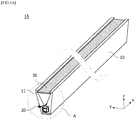
- FIG. 1A is a conceptual view illustrating a lighting device according to one embodiment of the present invention
- FIG. 1B is an enlarged view illustrating a portion A of FIG. 1A .
- the lighting device may include a housing 10, a light source module 20, and a lens 30.
- the housing 10 may include a first accommodation portion 12 in which the light source module 20 is disposed and a second accommodation portion 11 in which the lens 30 is disposed.
- the first accommodation portion 12 may extend in a first direction (X-axis direction) so that the light source module 20 may be inserted into the first accommodation portion 12.
- the second accommodation portion 11 may be a guide groove in which the lens 30 having a bar shape may be inserted into the guide groove.
- An opening 13 may connect the first accommodation portion 12 and the second accommodation portion 11.
- the opening 13 may have a tapered shape in which an area is increased in a direction from the first accommodation portion 12 to the second accommodation portion 11. Accordingly, the opening 13 may guide light emitted from the light source module 20 to the lens 30.
- an inner wall of the opening 13 may be coated with a reflective material.
- a molding member (not shown) may be disposed in at least one among the first accommodation portion 12, the second accommodation portion 11, and the opening 13 of the housing 10.
- the molding member may fix the light source module 20 and the lens 30 to the housing 10.
- the molding member is not specifically limited.
- a material of the molding member may also be the same as that of a light guide member 110.
- the light source module 20 may have a rod shape which extends in the first direction (X-axis direction). However, the light source module 20 is not necessarily limited thereto, and the light source module 20 may also have a bent shape. The shape of the light source module 20 is not specifically limited. A light-emitting portion 21 may be formed in a portion which faces the lens 30 in the light source module 20.
- the lens 30 extends in the first direction (X-axis direction) and concentrates light emitted through the light-emitting portion 21.
- the lens 30 may convert divergent light emitted from the light source module 20 to parallel light.
- the lens 30 may include a plurality of optical patterns (not shown) on one surface of the lens 30.
- the optical pattern may have a Fresnel shape and diffract light incident on the optical pattern.
- a height of the optical pattern may be changed in a continuous or discontinuous manner in a direction from a central portion to an edge of the lens 30.
- the height of the optical pattern may be designed to be decreased in the direction from the central portion to the edge or, conversely, may also be designed to be increased in the direction from the central portion to the edge.
- the lens 30 may be a Fresnel lens but is not necessarily limited thereto.
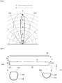
- FIG. 2 is an enlarged view illustrating a light source module
- FIG. 3 is a view illustrating a process in which light emitted from the light source module is concentrated
- FIG. 4 is a graph showing a light distribution curve of light emitted from the lighting device.
- the light source module 20 may include the light guide member 110 which extends in the first direction, a light-emitting element 100 disposed at one side of the light guide member 110, and a reflection member 120 which covers an outer circumferential surface of the light guide member 110.
- the light guide member 110 may be a light guide pipe having a predetermined length.
- the light guide member 110 may be freely bent to have various shapes.
- the light guide member 110 is illustrated to have a cylindrical shape, the light guide member 110 is not necessarily limited thereto and may also have a rectangular hexahedron shape or polygonal column shape instead of the cylindrical shape.
- an area of the light guide member 110 may be decreased or increased in the first direction (X-axis direction), and in a case in which the area is decreased in the first direction, light of the light-emitting element may be transmitted farther in the first direction (X-axis direction).
- the light-emitting element 100 may be a light-emitting diode (LED), a laser diode (LD), or an organic LED (OLED) but is not limited thereto.
- LED light-emitting diode
- LD laser diode
- OLED organic LED
- the light-emitting element 100 may be an LED.
- the LED may include an N-type conductive semiconductor layer, an active layer, and a P-type conductive semiconductor layer.
- Each of the N-type conductive semiconductor layer, the active layer, and the P-type conductive semiconductor layer of the LED may be formed of one or more semiconductor materials having a composition formula of Al x In y Ga (1-x-y) N (0 ⁇ x ⁇ 1, 0 ⁇ y ⁇ 1, 0 ⁇ x+y ⁇ 1), such as GaN, InAlGaN, AlGaAs, GaP, GaAs, GaAsP, and AlGaInP, but is not limited thereto.
- the light-emitting element 100 may also be a light-emitting element package in which a plurality of elements are packaged. For example, red, green, and blue (RGB) light-emitting elements may also be disposed in the light-emitting element 100 and selectively operated to realize a desired color.
- RGB red, green, and blue
- the light-emitting element 100 may also be an LD.
- the LD has advantages in that a divergent angle is easily adjusted and light is highly straight.
- the LD using even a single chip may provide sufficient optical power needed for a lamp due to high output power thereof. Accordingly, there may be an advantage in simplifying a drive circuit and an optical system.
- the reflection member 120 may cover the outer circumferential surface of the light guide member 110. As the reflection member 120 is formed of a material having high reflection efficiency, the reflection member 120 may serve to reduce optical loss. Since an opening of the reflection member 120 is formed in the first direction (X-axis direction), a part of the light guide member 110 may be exposed. Accordingly, the light guide member 110 may include the light-emitting portion 21 which extends in the first direction (X-axis direction).
- the reflection member 120 may be formed as a film type and may be formed of a synthetic resin containing a dispersed white pigment to realize a property of reflecting light and a property of facilitating light dispersion.
- titanium oxide, aluminum oxide, zinc oxide, lead carbonate, barium sulfate, calcium carbonate, or the like may be used for the white pigment
- polyethylene terephthalate, polyethylene naphthalate, acrylic resin, colicarbonate, polystyrene, polyolefin, cellulosic acid acetate, weather-resistant vinyl chloride, or the like may be used for the synthetic resin, but the present invention is not limited thereto.
- the light-emitting portion 21 may be disposed to face the lens 30 and may extend in the first direction.
- the light-emitting portion 21 may be a portion in which a part of the reflection member 120 is removed and the light guide member 110 is exposed through the part.
- the light-emitting portion 21 may have a predetermined width d1.
- the width d1 of the light-emitting portion 21 may be a distance in a second direction (Y-axis direction) perpendicular to the first direction.
- the light source module 20 While light emitted from the light-emitting element 100 is transmitted in the first direction, some light may be emitted through light-emitting portion 21. Accordingly, the light source module 20 emits linear light L1. That is, the linear light may be light emitted in the first direction (X-axis direction) and in a third direction (Z-axis direction) perpendicular to the second direction (Y-axis direction).
- the linear light L1 emitted from the light-emitting element 100 may be emitted toward the lens 30 and converted to parallel light L2 by the lens 30.
- the light-emitting portion 21 may be aligned with a central portion 31a having a dome shape.
- Heights of optical patterns 31a, 31b, and 31c may be changed in a continuous or discontinuous manner in the direction from the central portion to the edge of the lens 30.
- the heights of the optical patterns 31a, 31b, and 31c may be designed to be decreased in the direction from the central portion 31a having the dome shape to edges 31b and 31c, or, conversely, may also be designed to be increased in the direction from the central portion to the edges.
- An incident surface of the lens 30 may be a flat surface.
- the width d1 of the light-emitting portion 21 may range from 1 mm to 10 mm. In a case in which the width d1 of the light-emitting portion 21 is less than 1 mm, there is a problem in that an amount of light and a line width of the light are too small, and in a case in which the width is greater than 10 mm, an amount of light concentrated in the lens 30 becomes too small, and thus light loss may occur.
- a distance from the light source module 20 to the lens 30 needs to be maintained to have a focal length HI of the lens 30.
- the focal length may be properly adjusted according to a kind of the lens 30, a kind of a light source, and the like.
- the line width of the linear light emitted from the lighting device may be 10 mm or more. However, the line width is not necessarily limited thereto, and the line width of the linear light emitted from the lighting device may be adjusted by various adjusting factors.
- light emitted from the lighting device has a narrow view angle in the X-axis direction and a narrow view angle in the Y-axis direction and thus may have a narrow divergent angle.
- a full width at half maximum (FWHM) may be 40° or less but is not limited thereto.
- the width of the light-emitting portion and/or the distance from the light-emitting portion to the lens may be adjusted to realize light having narrow light distribution and high luminous intensity.
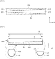
- FIG. 5 is a side view showing a state in which the light source module and a lens are spaced apart from each other
- FIG. 6 is a plan view illustrating the light source module
- FIG. 7 is a view showing a state in which a distance from the light source module to the lens is constant due to a submember.
- light emitted from the light-emitting element 100 is transmitted from the one side 111 to the other side 112 of the light guide member 110, and some of the light may be emitted toward the lens 30 through the light-emitting portion 21.
- the light guide member 110 may include beads (not shown). Such beads may serve to improve light reflection and diffusion properties.
- a density of the beads may be increased in the first direction, that is, away from the one side 111 of the light guide member 110. That is, less beads of the one side 111, in which an amount of light is relatively large, of the light guide member 110 are distributed, and more beads of the other side 112, in which an amount of light is relatively small, of the light guide member 110 are distributed so that uniformity can be improved.
- Contents of the beads may be properly adjusted to achieve a desired light diffusion effect and, more specifically, may be adjusted within a range from 0.01 to 0.3 wt% of a total resin.
- the beads may be formed of any one selected from among silicon, silica, glass bubble, Poly(methyl methacrylate) (PMMA), urethane, Zn, Zr, Al 2 O 3 , and acryl, and a particle diameter of the bead may range from 1 ⁇ m to 20 ⁇ m but is not limited thereto.
- PMMA Poly(methyl methacrylate)
- urethane Zn, Zr, Al 2 O 3 , and acryl
- a particle diameter of the bead may range from 1 ⁇ m to 20 ⁇ m but is not limited thereto.
- a method of improving light uniformity is not limited thereto, and various methods may be applied to improve the light uniformity.
- an amount of light may also be adjusted by increasing a density of reflective patterns in the first direction or corroding the light guide member 110 in the first direction.
- the width of the light-emitting portion 21 may be increased in the first direction (X-axis direction), that is, away from the one side 111 of the light guide member 110. That is, a width of a light-emitting portion 21a at one side may be smaller than a width of a light-emitting portion 21b at the other side.
- an amount of light of the one side 111 is relatively large, an amount of emitted light of the light-emitting portion may be decreased by decreasing the width of the one side 111.
- an amount of emitted light of the other side 112 may be increased by increasing the width of the light-emitting portion. Accordingly, an overall uniformity of linear light may be improved.
- a configuration to adjust the width of the light-emitting portion 21 is not specifically limited. For example, after an entirety of the light guide member 110 is coated with the reflection member 120, an etching depth thereof is adjusted in the first direction to increase an area of the light-emitting portion 21. Accordingly, a vertical distance from the light-emitting portion 21 to the lower end portion 22 of the light guide member 110 may be decreased in the first direction (X-axis direction).
- a width of the first accommodation portion 12 may be changed according to the width of the light-emitting portion 21.
- a length of the first accommodation portion 12 in the second direction y is less than a length of the light-emitting portion 21 in the second direction y
- light, which should be transmitted to the lens 30 may not be transmitted to the lens 30 by a step of the first accommodation portion 12 and may be reflected to the light guide member 110 or an interior of the first accommodation portion 12.
- the length of the first accommodation portion 12 in the second direction y may also be changed in the first direction x.
- a length of one side of the first accommodation portion 12 in the second direction y may be less than a length of the other side of the first accommodation portion 12 in the second direction y.
- the light source module 20 and the lens 30 may be spaced a predetermined distance from each other. Such a separation distance may be a focal length. Accordingly, an overall distance from the light source module 20 to the lens 30 may be maintained to be uniform in the first direction.
- the light source module 20 may be etched more in the first direction so that the thickness thereof may be decreased in the first direction. That is, since the thickness of the light source module 20 is decreased in the first direction, there is a problem in that a focal length of light emitted from the one side 111 of the light guide member 110 does not match a focal length of light emitted from the other side 112 (h2 ⁇ h3). Accordingly, light uniformity may be degraded.
- a submember 140 may be disposed under the light source module 20.
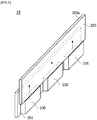
- FIG. 8 is a conceptual view illustrating a lighting device according to another embodiment of the present invention
- FIG. 9 is a conceptual view illustrating a lighting device according to still another embodiment of the present invention
- FIG. 10 is a view illustrating a lamp for an automobile according to an embodiment of the present invention.
- a light source module 20 may include a circuit board 201, a plurality of light-emitting elements 100 disposed on the circuit board 201, and a light guide plate 203 having one surface which faces the light-emitting elements 100 and the other surface 203a which faces one surface.
- the light-emitting element 100 may be a side surface LED but is not necessarily limited thereto.
- the light-emitting element 100 may also be a general top-type LED.
- the light guide plate 203 may have one surface which faces the light-emitting elements 100 and the other surface 203a which faces one surface.
- a thickness of the light guide plate 203 may range from 1 mm to 10 mm. That is, the other surface 203a of the light guide plate 203 may be a light-emitting portion.
- the light guide plate 203 is not necessarily limited thereto, and a structure having a reflective partition formed in an empty space may be substituted for the light guide plate.
- a housing may seal the remaining region except for the other surface 203a of the light guide plate, and a lens 30 may be disposed on the other surface 203a of the light guide plate.
- a light source module 20 may include a light-emitting element 100, a first lens 150 disposed on the light-emitting element 100, and a second lens 160 disposed on the first lens 150.
- the first lens 150 may serve a light concentration function
- the second lens 160 may serve a light diffusion function
- the first lens 150 may be a cylinder lens and the second lens 160 may be a diffusion plate, but the first lens 150 and the second lens 160 are not limited thereto.
- Light emitted from the light-emitting element 100 may be concentrated by the first lens 150, diffused by the second lens 160, and finally, converted to parallel light by a lens 30.
- the first lens 150 may be a convex lens having a cylindrical shape
- the second lens 160 may be a diffusion plate or diffusion member having a predetermined haze.
- FIG. 10 is a view illustrating a lamp for an automobile according to an embodiment of the present invention.
- the lighting device may include a lamp, a head lamp, a street light, or the like.
- the lighting device may further include a heat dissipation portion and a power supply which processes or converts an electric signal received from the outside to provide the processed or converted electric signal to a light source module.
- the lighting device may also be included in a head lamp 1 for an automobile.
- the head lamp 1 may include at least one among a high beam 1a, a lower beam 1b, a turn signal lamp 1c, and a daytime running lamp 1d.
- the lighting device may be realized as the daytime running lamp 1d.
- the lighting device is not necessarily limited thereto, and the lighting device according to the embodiment may also be used for a stop lamp of a tail lamp.
- the lighting device may also be installed in various lamps for an automobile in addition thereto.
Landscapes
- Engineering & Computer Science (AREA)
- General Engineering & Computer Science (AREA)
- Physics & Mathematics (AREA)
- Optics & Photonics (AREA)
- General Physics & Mathematics (AREA)
- Microelectronics & Electronic Packaging (AREA)
- Planar Illumination Modules (AREA)
- Non-Portable Lighting Devices Or Systems Thereof (AREA)
Abstract
Description
- The present invention relates to a lighting device and a lamp for an automobile including the same.
- Lighting devices are devices which light dark places using various light sources. The lighting devices are used to emit light to specific objects or places and express atmospheres using desired shapes or colors.
- In a case in which a lighting device of the conventional technology is used to express an atmosphere using a desired shape or color, there is a problem in that a configuration of the device is mechanically complex. Accordingly, a degree of design freedom is limited and it is difficult to install or operate the device.
- The lighting device of the conventional technology typically provides lighting with a desired shape using members such as a light guide plate and the like. However, such a lighting device generally has a problem in that luminous intensity is decreased.
- In addition, due to a limitation of the lighting device which should meet a predetermined standard and a configuration, there is a problem in forming the lighting device to be slim while ensuring desired light uniformity and luminous intensity in a limited place.
- The present invention is directed to providing a lighting device capable of increasing luminous intensity and a lamp for an automobile including the same.
- The present invention is directed to providing a lighting device capable of realizing various designs and a lamp for an automobile including the same.
- Objectives to be solved by embodiments are not limited to the above-described objectives and will include objectives and effects which can be identified by solutions for the objectives and the embodiments described below.
- One aspect of the present invention provides a lighting device including a light source module which extends in a first direction and a lens which is disposed on the light source module and extends in the first direction, wherein the light source module includes a light-emitting portion formed in the first direction, and the lens concentrates light emitted through the light-emitting portion.
- The lighting device may further include a housing including a first accommodation portion in which the light source module is disposed and a second accommodation portion in which the lens is disposed.
- The housing may include an opening which connects the first accommodation portion and the second accommodation portion, wherein the opening may have a tapered shape in which an area is increased in the direction from the first accommodation portion to the second accommodation portion.
- The lens may convert divergent light emitted through the light-emitting portion to parallel light.
- A width of the light-emitting portion may range from 1 mm to 10 mm.
- The light source module may include: a light guide member which extends in the first direction; a light-emitting element disposed at one side of the light guide member; and a reflection member which covers the light guide member, wherein the light-emitting portion may be disposed on the reflection member to expose the light guide member.
- The width of the light-emitting portion may be increased in a direction from the one side to the other side of the light guide member.
- A thickness of the light guide member may be decreased in the direction from the one side to the other side.
- The lighting device may further include a submember which is disposed under the light guide member and has a thickness which is increased in the direction from the one side to the other side.
- A first minimum distance from the one side to the lens may be equal to a second minimum distance from the other side to the lens.
- The light source module may include a circuit board, a plurality of light-emitting elements disposed on the circuit board, and a light guide plate including one surface which faces the light-emitting element and the other surface which faces the one surface, wherein light incident on the one surface of the light guide plate from the light-emitting element may be emitted through the other surface.
- The light source module may include a light-emitting element, a first lens disposed on the light-emitting element, and a second lens disposed on the first lens, wherein the first lens may serve a light concentration function and the second lens may serve a diffusion function.
- According to an embodiment, a linear light source with increased luminous intensity can be realized.
- A surface light source having various shapes can be realized. In addition, there are advantages in improving brightness uniformity and reducing a size and a weight thereof.
- In addition, the surface light source can be realized with high uniformity.
- Various useful advantages and effects of the present invention are not limited to the above-described advantages and may be understood in a process in which specific embodiments are described.
-
-
FIG. 1A is a conceptual view illustrating a lighting device according to one embodiment of the present invention. -
FIG. 1B is an enlarged view illustrating a portion A ofFIG. 1A . -
FIG. 2 is an enlarged view illustrating a light source module. -
FIG. 3 is a view illustrating a process in which light emitted from the light source module is concentrated. -
FIG. 4 is a graph showing a light distribution curve of light emitted from the lighting device. -
FIG. 5 is a side view showing a state in which the light source module and a lens are spaced apart from each other. -
FIG. 6 is a plan view illustrating the light source module. -
FIG. 7 is a view showing a state in which a distance from the light source module to the lens is constant due to a submember. -
FIG. 8 is a conceptual view illustrating a lighting device according to another embodiment of the present invention. -
FIG. 9 is a conceptual view illustrating a lighting device according to still another embodiment of the present invention. -
FIG. 10 is a view illustrating a lamp for an automobile according to an embodiment of the present invention. - Embodiments of the present invention may be modified into different forms or the plurality of embodiments may be combined, and the scope of the present invention is not limited to the embodiments which will be described below.
- Although a description given in a specific embodiment is not given in other embodiments, the description may be understood to be descriptions of other embodiments as long as there are no opposite or inconsistent descriptions given.
- For example, when a feature of an element A is described in a specific embodiment and a feature of an element B is described in another embodiment, the scope of the present invention includes an embodiment in which the elements A and B are combined even when the embodiment is not clearly described as long as there are no opposite or inconsistent descriptions given.
- In a description of the embodiment, in a case in which any one element is described as being formed on (or under) another element, such a description includes both a case in which the two elements are formed to be in direct contact with each other and a case in which the two elements are in indirect contact with each other such that one or more other elements are interposed between the two elements. In addition, in a case in which one element is described as being formed on (or under) an element, such a description may include a case in which one element is formed at an upper side or a lower side with respect to the element.
- Hereinafter, embodiments of the present invention will be described in detail with reference to the accompanying drawings so that those skilled in the art may easily perform the present invention.
-
FIG. 1A is a conceptual view illustrating a lighting device according to one embodiment of the present invention, andFIG. 1B is an enlarged view illustrating a portion A ofFIG. 1A . - Referring to
FIGS. 1A and1B , the lighting device according to the embodiment may include ahousing 10, alight source module 20, and alens 30. - The
housing 10 may include afirst accommodation portion 12 in which thelight source module 20 is disposed and asecond accommodation portion 11 in which thelens 30 is disposed. Thefirst accommodation portion 12 may extend in a first direction (X-axis direction) so that thelight source module 20 may be inserted into thefirst accommodation portion 12. Thesecond accommodation portion 11 may be a guide groove in which thelens 30 having a bar shape may be inserted into the guide groove. - An opening 13 may connect the
first accommodation portion 12 and thesecond accommodation portion 11. Theopening 13 may have a tapered shape in which an area is increased in a direction from thefirst accommodation portion 12 to thesecond accommodation portion 11. Accordingly, theopening 13 may guide light emitted from thelight source module 20 to thelens 30. In order to increase light extraction efficiency, an inner wall of theopening 13 may be coated with a reflective material. - A molding member (not shown) may be disposed in at least one among the
first accommodation portion 12, thesecond accommodation portion 11, and theopening 13 of thehousing 10. The molding member may fix thelight source module 20 and thelens 30 to thehousing 10. When the molding member is formed of a transparent material through which light emitted from a light-emittingelement 100 may pass, the molding member is not specifically limited. For example, a material of the molding member may also be the same as that of alight guide member 110. - The
light source module 20 may have a rod shape which extends in the first direction (X-axis direction). However, thelight source module 20 is not necessarily limited thereto, and thelight source module 20 may also have a bent shape. The shape of thelight source module 20 is not specifically limited. A light-emittingportion 21 may be formed in a portion which faces thelens 30 in thelight source module 20. - The
lens 30 extends in the first direction (X-axis direction) and concentrates light emitted through the light-emittingportion 21. Thelens 30 may convert divergent light emitted from thelight source module 20 to parallel light. - The
lens 30 may include a plurality of optical patterns (not shown) on one surface of thelens 30. The optical pattern may have a Fresnel shape and diffract light incident on the optical pattern. A height of the optical pattern may be changed in a continuous or discontinuous manner in a direction from a central portion to an edge of thelens 30. The height of the optical pattern may be designed to be decreased in the direction from the central portion to the edge or, conversely, may also be designed to be increased in the direction from the central portion to the edge. - The
lens 30 may be a Fresnel lens but is not necessarily limited thereto. -
FIG. 2 is an enlarged view illustrating a light source module,FIG. 3 is a view illustrating a process in which light emitted from the light source module is concentrated, andFIG. 4 is a graph showing a light distribution curve of light emitted from the lighting device. - Referring to
FIG. 2 , thelight source module 20 may include thelight guide member 110 which extends in the first direction, a light-emittingelement 100 disposed at one side of thelight guide member 110, and areflection member 120 which covers an outer circumferential surface of thelight guide member 110. - Various kinds of light guide members which may guide light in a longitudinal direction may be applied to the
light guide member 110. For example, thelight guide member 110 may be a light guide pipe having a predetermined length. Thelight guide member 110 may be freely bent to have various shapes. For example, although thelight guide member 110 is illustrated to have a cylindrical shape, thelight guide member 110 is not necessarily limited thereto and may also have a rectangular hexahedron shape or polygonal column shape instead of the cylindrical shape. In addition, an area of thelight guide member 110 may be decreased or increased in the first direction (X-axis direction), and in a case in which the area is decreased in the first direction, light of the light-emitting element may be transmitted farther in the first direction (X-axis direction). - Various elements capable of emitting light may be selected as the light-emitting
element 100. For example, the light-emittingelement 100 may be a light-emitting diode (LED), a laser diode (LD), or an organic LED (OLED) but is not limited thereto. - For example, the light-emitting
element 100 may be an LED. The LED may include an N-type conductive semiconductor layer, an active layer, and a P-type conductive semiconductor layer. Each of the N-type conductive semiconductor layer, the active layer, and the P-type conductive semiconductor layer of the LED may be formed of one or more semiconductor materials having a composition formula of AlxInyGa(1-x-y)N (0≤x≤1, 0≤y≤1, 0≤x+y≤1), such as GaN, InAlGaN, AlGaAs, GaP, GaAs, GaAsP, and AlGaInP, but is not limited thereto. - The light-emitting
element 100 may also be a light-emitting element package in which a plurality of elements are packaged. For example, red, green, and blue (RGB) light-emitting elements may also be disposed in the light-emittingelement 100 and selectively operated to realize a desired color. - The light-emitting
element 100 may also be an LD. The LD has advantages in that a divergent angle is easily adjusted and light is highly straight. The LD using even a single chip may provide sufficient optical power needed for a lamp due to high output power thereof. Accordingly, there may be an advantage in simplifying a drive circuit and an optical system. - The
reflection member 120 may cover the outer circumferential surface of thelight guide member 110. As thereflection member 120 is formed of a material having high reflection efficiency, thereflection member 120 may serve to reduce optical loss. Since an opening of thereflection member 120 is formed in the first direction (X-axis direction), a part of thelight guide member 110 may be exposed. Accordingly, thelight guide member 110 may include the light-emittingportion 21 which extends in the first direction (X-axis direction). - The
reflection member 120 may be formed as a film type and may be formed of a synthetic resin containing a dispersed white pigment to realize a property of reflecting light and a property of facilitating light dispersion. - For example, titanium oxide, aluminum oxide, zinc oxide, lead carbonate, barium sulfate, calcium carbonate, or the like may be used for the white pigment, and polyethylene terephthalate, polyethylene naphthalate, acrylic resin, colicarbonate, polystyrene, polyolefin, cellulosic acid acetate, weather-resistant vinyl chloride, or the like may be used for the synthetic resin, but the present invention is not limited thereto.
- The light-emitting
portion 21 may be disposed to face thelens 30 and may extend in the first direction. The light-emittingportion 21 may be a portion in which a part of thereflection member 120 is removed and thelight guide member 110 is exposed through the part. In order to realize linear light, the light-emittingportion 21 may have a predetermined width d1. The width d1 of the light-emittingportion 21 may be a distance in a second direction (Y-axis direction) perpendicular to the first direction. - While light emitted from the light-emitting
element 100 is transmitted in the first direction, some light may be emitted through light-emittingportion 21. Accordingly, thelight source module 20 emits linear light L1. That is, the linear light may be light emitted in the first direction (X-axis direction) and in a third direction (Z-axis direction) perpendicular to the second direction (Y-axis direction). - Referring to
FIG. 3 , the linear light L1 emitted from the light-emittingelement 100 may be emitted toward thelens 30 and converted to parallel light L2 by thelens 30. The light-emittingportion 21 may be aligned with acentral portion 31a having a dome shape. - Heights of
optical patterns lens 30. The heights of theoptical patterns central portion 31a having the dome shape toedges lens 30 may be a flat surface. - The width d1 of the light-emitting
portion 21 may range from 1 mm to 10 mm. In a case in which the width d1 of the light-emittingportion 21 is less than 1 mm, there is a problem in that an amount of light and a line width of the light are too small, and in a case in which the width is greater than 10 mm, an amount of light concentrated in thelens 30 becomes too small, and thus light loss may occur. - A distance from the
light source module 20 to thelens 30 needs to be maintained to have a focal length HI of thelens 30. The focal length may be properly adjusted according to a kind of thelens 30, a kind of a light source, and the like. The line width of the linear light emitted from the lighting device may be 10 mm or more. However, the line width is not necessarily limited thereto, and the line width of the linear light emitted from the lighting device may be adjusted by various adjusting factors. - Referring to
FIG. 4 , it may be seen that light emitted from the lighting device has a narrow view angle in the X-axis direction and a narrow view angle in the Y-axis direction and thus may have a narrow divergent angle. For example, a full width at half maximum (FWHM) may be 40° or less but is not limited thereto. According to the embodiment, the width of the light-emitting portion and/or the distance from the light-emitting portion to the lens, that is, the focal length of the lens, may be adjusted to realize light having narrow light distribution and high luminous intensity. -
FIG. 5 is a side view showing a state in which the light source module and a lens are spaced apart from each other,FIG. 6 is a plan view illustrating the light source module, andFIG. 7 is a view showing a state in which a distance from the light source module to the lens is constant due to a submember. - Referring to
FIGS. 5 and6 , light emitted from the light-emittingelement 100 is transmitted from the oneside 111 to theother side 112 of thelight guide member 110, and some of the light may be emitted toward thelens 30 through the light-emittingportion 21. - According to the embodiment, in order to maintain light uniformity in the first direction (X-axis direction), the
light guide member 110 may include beads (not shown). Such beads may serve to improve light reflection and diffusion properties. - A density of the beads may be increased in the first direction, that is, away from the one
side 111 of thelight guide member 110. That is, less beads of the oneside 111, in which an amount of light is relatively large, of thelight guide member 110 are distributed, and more beads of theother side 112, in which an amount of light is relatively small, of thelight guide member 110 are distributed so that uniformity can be improved. - As a result, an amount of emitted light is increased and uniformity is improved. Accordingly, a brightness of the lighting device can be increased.
- Contents of the beads may be properly adjusted to achieve a desired light diffusion effect and, more specifically, may be adjusted within a range from 0.01 to 0.3 wt% of a total resin.
- The beads may be formed of any one selected from among silicon, silica, glass bubble, Poly(methyl methacrylate) (PMMA), urethane, Zn, Zr, Al2O3, and acryl, and a particle diameter of the bead may range from 1 µm to 20 µm but is not limited thereto.
- A method of improving light uniformity is not limited thereto, and various methods may be applied to improve the light uniformity. For example, an amount of light may also be adjusted by increasing a density of reflective patterns in the first direction or corroding the
light guide member 110 in the first direction. - The width of the light-emitting
portion 21 may be increased in the first direction (X-axis direction), that is, away from the oneside 111 of thelight guide member 110. That is, a width of a light-emittingportion 21a at one side may be smaller than a width of a light-emittingportion 21b at the other side. - Since an amount of light of the one
side 111 is relatively large, an amount of emitted light of the light-emitting portion may be decreased by decreasing the width of the oneside 111. In addition, an amount of emitted light of theother side 112 may be increased by increasing the width of the light-emitting portion. Accordingly, an overall uniformity of linear light may be improved. - A configuration to adjust the width of the light-emitting
portion 21 is not specifically limited. For example, after an entirety of thelight guide member 110 is coated with thereflection member 120, an etching depth thereof is adjusted in the first direction to increase an area of the light-emittingportion 21. Accordingly, a vertical distance from the light-emittingportion 21 to thelower end portion 22 of thelight guide member 110 may be decreased in the first direction (X-axis direction). - A width of the first accommodation portion 12 (see
FIG. 1B ) may be changed according to the width of the light-emittingportion 21. For example, in a case in which a length of thefirst accommodation portion 12 in the second direction y is less than a length of the light-emittingportion 21 in the second direction y, light, which should be transmitted to thelens 30, may not be transmitted to thelens 30 by a step of thefirst accommodation portion 12 and may be reflected to thelight guide member 110 or an interior of thefirst accommodation portion 12. Accordingly, the length of thefirst accommodation portion 12 in the second direction y may also be changed in the first direction x. For example, a length of one side of thefirst accommodation portion 12 in the second direction y may be less than a length of the other side of thefirst accommodation portion 12 in the second direction y. - Referring to
FIG. 5 , thelight source module 20 and thelens 30 may be spaced a predetermined distance from each other. Such a separation distance may be a focal length. Accordingly, an overall distance from thelight source module 20 to thelens 30 may be maintained to be uniform in the first direction. - The
light source module 20 may be etched more in the first direction so that the thickness thereof may be decreased in the first direction. That is, since the thickness of thelight source module 20 is decreased in the first direction, there is a problem in that a focal length of light emitted from the oneside 111 of thelight guide member 110 does not match a focal length of light emitted from the other side 112 (h2<h3). Accordingly, light uniformity may be degraded. - Referring to
FIG. 7 , asubmember 140 may be disposed under thelight source module 20. Such asubmember 140 may have a shape in which a thickness thereof is increased in the first direction. Accordingly, when thelight source module 20 is mounted on thesubmember 140, the distance from thelight source module 20 to thelens 30 may be controlled to be constant in the first direction (h2=h3). Accordingly, uniformity can be improved. -
FIG. 8 is a conceptual view illustrating a lighting device according to another embodiment of the present invention,FIG. 9 is a conceptual view illustrating a lighting device according to still another embodiment of the present invention, andFIG. 10 is a view illustrating a lamp for an automobile according to an embodiment of the present invention. - Referring to
FIG. 8 , alight source module 20 may include acircuit board 201, a plurality of light-emittingelements 100 disposed on thecircuit board 201, and alight guide plate 203 having one surface which faces the light-emittingelements 100 and theother surface 203a which faces one surface. - The light-emitting
element 100 may be a side surface LED but is not necessarily limited thereto. For example, the light-emittingelement 100 may also be a general top-type LED. - The
light guide plate 203 may have one surface which faces the light-emittingelements 100 and theother surface 203a which faces one surface. Here, a thickness of thelight guide plate 203 may range from 1 mm to 10 mm. That is, theother surface 203a of thelight guide plate 203 may be a light-emitting portion. However, thelight guide plate 203 is not necessarily limited thereto, and a structure having a reflective partition formed in an empty space may be substituted for the light guide plate. - Although not illustrated in the drawing, a housing may seal the remaining region except for the
other surface 203a of the light guide plate, and alens 30 may be disposed on theother surface 203a of the light guide plate. - Referring to
FIG. 9 , alight source module 20 may include a light-emittingelement 100, afirst lens 150 disposed on the light-emittingelement 100, and asecond lens 160 disposed on thefirst lens 150. - Here, the
first lens 150 may serve a light concentration function, and thesecond lens 160 may serve a light diffusion function. For example, thefirst lens 150 may be a cylinder lens and thesecond lens 160 may be a diffusion plate, but thefirst lens 150 and thesecond lens 160 are not limited thereto. - Light emitted from the light-emitting
element 100 may be concentrated by thefirst lens 150, diffused by thesecond lens 160, and finally, converted to parallel light by alens 30. Thefirst lens 150 may be a convex lens having a cylindrical shape, and thesecond lens 160 may be a diffusion plate or diffusion member having a predetermined haze. -
FIG. 10 is a view illustrating a lamp for an automobile according to an embodiment of the present invention. - The lighting device according to the embodiment may include a lamp, a head lamp, a street light, or the like. In a case in which the lighting device is used as a general lighting, the lighting device may further include a heat dissipation portion and a power supply which processes or converts an electric signal received from the outside to provide the processed or converted electric signal to a light source module.
- In addition, the lighting device may also be included in a
head lamp 1 for an automobile. Thehead lamp 1 may include at least one among ahigh beam 1a, alower beam 1b, aturn signal lamp 1c, and adaytime running lamp 1d. According to the embodiment, the lighting device may be realized as thedaytime running lamp 1d. However, the lighting device is not necessarily limited thereto, and the lighting device according to the embodiment may also be used for a stop lamp of a tail lamp. However, the lighting device may also be installed in various lamps for an automobile in addition thereto.
Claims (10)
- A lighting device comprising:a light source module which extends in a first direction; anda lens which is disposed on the light source module and extends in the first direction,wherein the light source module includes a light guide member which extends in the first direction,a light-emitting element which is disposed at one side of the light guide member, anda reflection member which is disposed on an outer circumferential surface of the light guide member, andthe light guide member includes a light-emitting portion which extends in the first direction.
- The lighting device of claim 1, further comprising a housing including a first accommodation portion in which the light source module is disposed and a second accommodation portion in which the lens is disposed.
- The lighting device of claim 2, wherein the housing includes an opening which connects the first accommodation portion and the second accommodation portion,
wherein the opening has a tapered shape in which an area is increased in a direction from the first accommodation portion to the second accommodation portion. - The lighting device of claim 1, wherein the lens converts divergent light emitted through the light-emitting portion to parallel light.
- The lighting device of claim 1, wherein a width of the light-emitting portion ranges from 1 mm to 10 mm.
- The lighting device of claim 1, wherein a width of the light-emitting portion is increased in a direction from the one side to the other side of the light guide member.
- The lighting device of claim 1, wherein a thickness of the light guide member is decreased in a direction from the one side to the other side of the light guide member.
- The lighting device of claim 7, further comprising a submember which is disposed under the light guide member and has a thickness which is increased in the direction from the one side to the other side.
- The lighting device of claim 8, wherein a first minimum distance from the one side to the lens is equal to a second minimum distance from the other side to the lens.
- A lamp for an automobile, comprising the lighting device of claim 1.
Applications Claiming Priority (2)
| Application Number | Priority Date | Filing Date | Title |
|---|---|---|---|
| KR1020160166811A KR102693625B1 (en) | 2016-12-08 | 2016-12-08 | Light unit and Lamp unit for automobile of using the same |
| PCT/KR2017/014358 WO2018106052A1 (en) | 2016-12-08 | 2017-12-08 | Lighting device and lamp for automobile including same |
Publications (3)
| Publication Number | Publication Date |
|---|---|
| EP3553368A1 true EP3553368A1 (en) | 2019-10-16 |
| EP3553368A4 EP3553368A4 (en) | 2019-11-20 |
| EP3553368B1 EP3553368B1 (en) | 2021-05-19 |
Family
ID=62491205
Family Applications (1)
| Application Number | Title | Priority Date | Filing Date |
|---|---|---|---|
| EP17877923.7A Active EP3553368B1 (en) | 2016-12-08 | 2017-12-08 | Lighting device and lamp for automobile including same |
Country Status (5)
| Country | Link |
|---|---|
| US (1) | US10859226B2 (en) |
| EP (1) | EP3553368B1 (en) |
| KR (1) | KR102693625B1 (en) |
| CN (1) | CN110073138A (en) |
| WO (1) | WO2018106052A1 (en) |
Families Citing this family (10)
| Publication number | Priority date | Publication date | Assignee | Title |
|---|---|---|---|---|
| KR20220124433A (en) | 2021-03-03 | 2022-09-14 | 에스엘 주식회사 | car lamp |
| CN115480336B (en) * | 2021-06-15 | 2025-03-21 | 群光电能科技股份有限公司 | Light guide module |
| KR20230036667A (en) | 2021-09-08 | 2023-03-15 | 에스엘 주식회사 | Lamp for vehicle |
| CN116068776A (en) * | 2021-10-29 | 2023-05-05 | 华为技术有限公司 | A spectroscopic method and related equipment |
| KR20230098954A (en) | 2021-12-27 | 2023-07-04 | 에스엘 주식회사 | Lamp for vehicle |
| KR20230121318A (en) | 2022-02-11 | 2023-08-18 | 에스엘 주식회사 | Lamp for vehicle |
| KR20230122830A (en) | 2022-02-15 | 2023-08-22 | 에스엘 주식회사 | Lamp module and lamp for vehicle including the same |
| KR20230125567A (en) | 2022-02-21 | 2023-08-29 | 에스엘 주식회사 | Lamp module and lamp for vehicle including the same |
| KR20230129643A (en) | 2022-03-02 | 2023-09-11 | 에스엘 주식회사 | Lamp for vehicle |
| KR20240044027A (en) | 2022-09-28 | 2024-04-04 | 에스엘 주식회사 | Lamp module and lamp for vehicle including the same |
Family Cites Families (21)
| Publication number | Priority date | Publication date | Assignee | Title |
|---|---|---|---|---|
| CN1328746C (en) * | 2001-08-31 | 2007-07-25 | 库尔选项公司 | Thermally conductive lamp reflector |
| JP3961808B2 (en) * | 2001-10-23 | 2007-08-22 | 株式会社小糸製作所 | Vehicle lighting |
| US6641284B2 (en) * | 2002-02-21 | 2003-11-04 | Whelen Engineering Company, Inc. | LED light assembly |
| TW200409996A (en) * | 2002-12-12 | 2004-06-16 | Samsung Electronics Co Ltd | Light guide plate with stepped edge and display device having the same |
| JP5083205B2 (en) * | 2006-03-10 | 2012-11-28 | 日亜化学工業株式会社 | Light emitting device |
| JP2008244985A (en) * | 2007-03-28 | 2008-10-09 | Mitsubishi Electric Corp | Line illumination device and image input device using the same |
| CN101284506A (en) * | 2008-04-28 | 2008-10-15 | 甄磊 | Reflector for automobile lamps |
| JP5275776B2 (en) | 2008-12-17 | 2013-08-28 | 株式会社小糸製作所 | Vehicle lighting |
| CN202082812U (en) * | 2010-04-16 | 2011-12-21 | 吕大明 | Top-sharing non-coaxial multiple-tapered-tangential-plane deep opening LED reflecting shade |
| JP5463462B2 (en) * | 2010-06-08 | 2014-04-09 | 株式会社オプトデザイン | Planar light source device and illumination device |
| US20110140148A1 (en) * | 2010-07-15 | 2011-06-16 | Pinecone Energies, Inc. | Optical device for semiconductor based lamp |
| JP5903950B2 (en) * | 2012-03-14 | 2016-04-13 | 三菱電機株式会社 | Line light source for image reading |
| US20130272027A1 (en) | 2012-04-11 | 2013-10-17 | Shenzhen China Star Optoelectronics Technology Co., Ltd. | Method for Manufacturing LED Light Bar and LED Light Bar and Backlight Module |
| CN102661523B (en) * | 2012-04-11 | 2015-07-01 | 深圳市华星光电技术有限公司 | LED lamp strip, method for manufacturing same and backlight module |
| DE102012108855B4 (en) * | 2012-09-20 | 2025-10-09 | HELLA GmbH & Co. KGaA | Light guides for vehicles |
| JP6174329B2 (en) | 2013-02-07 | 2017-08-02 | 株式会社小糸製作所 | Vehicle lighting |
| US10545279B2 (en) * | 2013-07-18 | 2020-01-28 | Quarkstar Llc | Modular light guide luminaires |
| CN203868881U (en) * | 2014-03-26 | 2014-10-08 | 佛山市南海区艾依迪照明有限公司 | Automobile lamp device capable of switching high beam and low beam |
| CN110617458A (en) | 2014-05-28 | 2019-12-27 | 夸克星有限责任公司 | Lamp assembly |
| JP6520003B2 (en) * | 2014-07-25 | 2019-05-29 | 市光工業株式会社 | Vehicle lamp |
| JP6007280B1 (en) * | 2015-04-08 | 2016-10-12 | 古河電気工業株式会社 | Linear light guide, linear light guide structure, lighting device |
-
2016
- 2016-12-08 KR KR1020160166811A patent/KR102693625B1/en active Active
-
2017
- 2017-12-08 CN CN201780076220.4A patent/CN110073138A/en active Pending
- 2017-12-08 WO PCT/KR2017/014358 patent/WO2018106052A1/en not_active Ceased
- 2017-12-08 EP EP17877923.7A patent/EP3553368B1/en active Active
- 2017-12-08 US US16/467,236 patent/US10859226B2/en active Active
Also Published As
| Publication number | Publication date |
|---|---|
| EP3553368B1 (en) | 2021-05-19 |
| KR20180065661A (en) | 2018-06-18 |
| WO2018106052A1 (en) | 2018-06-14 |
| US10859226B2 (en) | 2020-12-08 |
| EP3553368A4 (en) | 2019-11-20 |
| US20200080697A1 (en) | 2020-03-12 |
| KR102693625B1 (en) | 2024-08-09 |
| CN110073138A (en) | 2019-07-30 |
Similar Documents
| Publication | Publication Date | Title |
|---|---|---|
| EP3553368B1 (en) | Lighting device and lamp for automobile including same | |
| KR102603695B1 (en) | Light emitting device and vehicle lamp comprising the same | |
| KR102594815B1 (en) | Lighting module and lighting apparatus | |
| JP2012195404A (en) | Light-emitting device and luminaire | |
| KR20190132124A (en) | Lighting module and lighting apparatus | |
| US11353193B2 (en) | Lighting module and lighting device comprising same | |
| US9746145B2 (en) | Light-emitting device with non-successive placement of light-emitting elements of one color, illumination light source having the same, and illumination device having the same | |
| KR20220137416A (en) | Lighting device | |
| US8203156B2 (en) | Light-emitting diode structure | |
| KR20240012590A (en) | Lighting module and lighting apparatus | |
| US10955113B2 (en) | Light-emitting module | |
| US20230135095A1 (en) | Lighting module and lighting device | |
| KR102640552B1 (en) | Lighting module and lighting apparatus having thereof | |
| KR102160775B1 (en) | A light emitting device package | |
| CN204201685U (en) | Ligthing paraphernalia | |
| KR20200126290A (en) | Lighting module and lighting apparatus | |
| KR102288768B1 (en) | Lighting module and lighting apparatus | |
| KR20210034398A (en) | Lighting module, lighting apparatus and lamp | |
| JP2005229083A (en) | Packaging of light-emitting diode | |
| KR102584543B1 (en) | Lighting module and lighting apparatus | |
| KR20120077252A (en) | Light-emitting package | |
| KR20210109124A (en) | Lighting Device | |
| US12410901B2 (en) | Lighting device | |
| KR102905089B1 (en) | Lighing apparatus and lamp including the same | |
| KR102730389B1 (en) | Lighting apparatus |
Legal Events
| Date | Code | Title | Description |
|---|---|---|---|
| STAA | Information on the status of an ep patent application or granted ep patent |
Free format text: STATUS: THE INTERNATIONAL PUBLICATION HAS BEEN MADE |
|
| PUAI | Public reference made under article 153(3) epc to a published international application that has entered the european phase |
Free format text: ORIGINAL CODE: 0009012 |
|
| STAA | Information on the status of an ep patent application or granted ep patent |
Free format text: STATUS: REQUEST FOR EXAMINATION WAS MADE |
|
| 17P | Request for examination filed |
Effective date: 20190704 |
|
| AK | Designated contracting states |
Kind code of ref document: A1 Designated state(s): AL AT BE BG CH CY CZ DE DK EE ES FI FR GB GR HR HU IE IS IT LI LT LU LV MC MK MT NL NO PL PT RO RS SE SI SK SM TR |
|
| AX | Request for extension of the european patent |
Extension state: BA ME |
|
| A4 | Supplementary search report drawn up and despatched |
Effective date: 20191022 |
|
| RIC1 | Information provided on ipc code assigned before grant |
Ipc: F21S 41/00 20180101AFI20191016BHEP Ipc: F21S 4/28 20160101ALI20191016BHEP Ipc: F21S 41/24 20180101ALI20191016BHEP Ipc: G02B 1/04 20060101ALI20191016BHEP Ipc: F21S 43/237 20180101ALI20191016BHEP Ipc: F21S 10/00 20060101ALI20191016BHEP |
|
| DAV | Request for validation of the european patent (deleted) | ||
| DAX | Request for extension of the european patent (deleted) | ||
| RIC1 | Information provided on ipc code assigned before grant |
Ipc: F21S 41/00 20180101AFI20201106BHEP Ipc: F21S 41/24 20180101ALI20201106BHEP Ipc: G02B 1/04 20060101ALI20201106BHEP Ipc: F21S 10/00 20060101ALI20201106BHEP Ipc: F21S 4/28 20160101ALI20201106BHEP Ipc: F21S 43/237 20180101ALI20201106BHEP |
|
| GRAP | Despatch of communication of intention to grant a patent |
Free format text: ORIGINAL CODE: EPIDOSNIGR1 |
|
| STAA | Information on the status of an ep patent application or granted ep patent |
Free format text: STATUS: GRANT OF PATENT IS INTENDED |
|
| INTG | Intention to grant announced |
Effective date: 20201218 |
|
| GRAS | Grant fee paid |
Free format text: ORIGINAL CODE: EPIDOSNIGR3 |
|
| GRAA | (expected) grant |
Free format text: ORIGINAL CODE: 0009210 |
|
| STAA | Information on the status of an ep patent application or granted ep patent |
Free format text: STATUS: THE PATENT HAS BEEN GRANTED |
|
| AK | Designated contracting states |
Kind code of ref document: B1 Designated state(s): AL AT BE BG CH CY CZ DE DK EE ES FI FR GB GR HR HU IE IS IT LI LT LU LV MC MK MT NL NO PL PT RO RS SE SI SK SM TR |
|
| REG | Reference to a national code |
Ref country code: GB Ref legal event code: FG4D |
|
| REG | Reference to a national code |
Ref country code: CH Ref legal event code: EP |
|
| REG | Reference to a national code |
Ref country code: DE Ref legal event code: R096 Ref document number: 602017039025 Country of ref document: DE |
|
| REG | Reference to a national code |
Ref country code: AT Ref legal event code: REF Ref document number: 1394305 Country of ref document: AT Kind code of ref document: T Effective date: 20210615 |
|
| REG | Reference to a national code |
Ref country code: IE Ref legal event code: FG4D |
|
| REG | Reference to a national code |
Ref country code: LT Ref legal event code: MG9D |
|
| REG | Reference to a national code |
Ref country code: AT Ref legal event code: MK05 Ref document number: 1394305 Country of ref document: AT Kind code of ref document: T Effective date: 20210519 |
|
| REG | Reference to a national code |
Ref country code: NL Ref legal event code: MP Effective date: 20210519 |
|
| PG25 | Lapsed in a contracting state [announced via postgrant information from national office to epo] |
Ref country code: BG Free format text: LAPSE BECAUSE OF FAILURE TO SUBMIT A TRANSLATION OF THE DESCRIPTION OR TO PAY THE FEE WITHIN THE PRESCRIBED TIME-LIMIT Effective date: 20210819 Ref country code: AT Free format text: LAPSE BECAUSE OF FAILURE TO SUBMIT A TRANSLATION OF THE DESCRIPTION OR TO PAY THE FEE WITHIN THE PRESCRIBED TIME-LIMIT Effective date: 20210519 Ref country code: HR Free format text: LAPSE BECAUSE OF FAILURE TO SUBMIT A TRANSLATION OF THE DESCRIPTION OR TO PAY THE FEE WITHIN THE PRESCRIBED TIME-LIMIT Effective date: 20210519 Ref country code: FI Free format text: LAPSE BECAUSE OF FAILURE TO SUBMIT A TRANSLATION OF THE DESCRIPTION OR TO PAY THE FEE WITHIN THE PRESCRIBED TIME-LIMIT Effective date: 20210519 Ref country code: LT Free format text: LAPSE BECAUSE OF FAILURE TO SUBMIT A TRANSLATION OF THE DESCRIPTION OR TO PAY THE FEE WITHIN THE PRESCRIBED TIME-LIMIT Effective date: 20210519 |
|
| PG25 | Lapsed in a contracting state [announced via postgrant information from national office to epo] |
Ref country code: PL Free format text: LAPSE BECAUSE OF FAILURE TO SUBMIT A TRANSLATION OF THE DESCRIPTION OR TO PAY THE FEE WITHIN THE PRESCRIBED TIME-LIMIT Effective date: 20210519 Ref country code: NO Free format text: LAPSE BECAUSE OF FAILURE TO SUBMIT A TRANSLATION OF THE DESCRIPTION OR TO PAY THE FEE WITHIN THE PRESCRIBED TIME-LIMIT Effective date: 20210819 Ref country code: PT Free format text: LAPSE BECAUSE OF FAILURE TO SUBMIT A TRANSLATION OF THE DESCRIPTION OR TO PAY THE FEE WITHIN THE PRESCRIBED TIME-LIMIT Effective date: 20210920 Ref country code: LV Free format text: LAPSE BECAUSE OF FAILURE TO SUBMIT A TRANSLATION OF THE DESCRIPTION OR TO PAY THE FEE WITHIN THE PRESCRIBED TIME-LIMIT Effective date: 20210519 Ref country code: SE Free format text: LAPSE BECAUSE OF FAILURE TO SUBMIT A TRANSLATION OF THE DESCRIPTION OR TO PAY THE FEE WITHIN THE PRESCRIBED TIME-LIMIT Effective date: 20210519 Ref country code: RS Free format text: LAPSE BECAUSE OF FAILURE TO SUBMIT A TRANSLATION OF THE DESCRIPTION OR TO PAY THE FEE WITHIN THE PRESCRIBED TIME-LIMIT Effective date: 20210519 Ref country code: GR Free format text: LAPSE BECAUSE OF FAILURE TO SUBMIT A TRANSLATION OF THE DESCRIPTION OR TO PAY THE FEE WITHIN THE PRESCRIBED TIME-LIMIT Effective date: 20210820 Ref country code: IS Free format text: LAPSE BECAUSE OF FAILURE TO SUBMIT A TRANSLATION OF THE DESCRIPTION OR TO PAY THE FEE WITHIN THE PRESCRIBED TIME-LIMIT Effective date: 20210919 |
|
| PG25 | Lapsed in a contracting state [announced via postgrant information from national office to epo] |
Ref country code: NL Free format text: LAPSE BECAUSE OF FAILURE TO SUBMIT A TRANSLATION OF THE DESCRIPTION OR TO PAY THE FEE WITHIN THE PRESCRIBED TIME-LIMIT Effective date: 20210519 |
|
| PG25 | Lapsed in a contracting state [announced via postgrant information from national office to epo] |
Ref country code: EE Free format text: LAPSE BECAUSE OF FAILURE TO SUBMIT A TRANSLATION OF THE DESCRIPTION OR TO PAY THE FEE WITHIN THE PRESCRIBED TIME-LIMIT Effective date: 20210519 Ref country code: ES Free format text: LAPSE BECAUSE OF FAILURE TO SUBMIT A TRANSLATION OF THE DESCRIPTION OR TO PAY THE FEE WITHIN THE PRESCRIBED TIME-LIMIT Effective date: 20210519 Ref country code: SM Free format text: LAPSE BECAUSE OF FAILURE TO SUBMIT A TRANSLATION OF THE DESCRIPTION OR TO PAY THE FEE WITHIN THE PRESCRIBED TIME-LIMIT Effective date: 20210519 Ref country code: SK Free format text: LAPSE BECAUSE OF FAILURE TO SUBMIT A TRANSLATION OF THE DESCRIPTION OR TO PAY THE FEE WITHIN THE PRESCRIBED TIME-LIMIT Effective date: 20210519 Ref country code: CZ Free format text: LAPSE BECAUSE OF FAILURE TO SUBMIT A TRANSLATION OF THE DESCRIPTION OR TO PAY THE FEE WITHIN THE PRESCRIBED TIME-LIMIT Effective date: 20210519 Ref country code: DK Free format text: LAPSE BECAUSE OF FAILURE TO SUBMIT A TRANSLATION OF THE DESCRIPTION OR TO PAY THE FEE WITHIN THE PRESCRIBED TIME-LIMIT Effective date: 20210519 Ref country code: RO Free format text: LAPSE BECAUSE OF FAILURE TO SUBMIT A TRANSLATION OF THE DESCRIPTION OR TO PAY THE FEE WITHIN THE PRESCRIBED TIME-LIMIT Effective date: 20210519 |
|
| REG | Reference to a national code |
Ref country code: DE Ref legal event code: R097 Ref document number: 602017039025 Country of ref document: DE |
|
| PLBE | No opposition filed within time limit |
Free format text: ORIGINAL CODE: 0009261 |
|
| STAA | Information on the status of an ep patent application or granted ep patent |
Free format text: STATUS: NO OPPOSITION FILED WITHIN TIME LIMIT |
|
| 26N | No opposition filed |
Effective date: 20220222 |
|
| PG25 | Lapsed in a contracting state [announced via postgrant information from national office to epo] |
Ref country code: IS Free format text: LAPSE BECAUSE OF FAILURE TO SUBMIT A TRANSLATION OF THE DESCRIPTION OR TO PAY THE FEE WITHIN THE PRESCRIBED TIME-LIMIT Effective date: 20210919 Ref country code: AL Free format text: LAPSE BECAUSE OF FAILURE TO SUBMIT A TRANSLATION OF THE DESCRIPTION OR TO PAY THE FEE WITHIN THE PRESCRIBED TIME-LIMIT Effective date: 20210519 |
|
| PG25 | Lapsed in a contracting state [announced via postgrant information from national office to epo] |
Ref country code: MC Free format text: LAPSE BECAUSE OF FAILURE TO SUBMIT A TRANSLATION OF THE DESCRIPTION OR TO PAY THE FEE WITHIN THE PRESCRIBED TIME-LIMIT Effective date: 20210519 Ref country code: IT Free format text: LAPSE BECAUSE OF FAILURE TO SUBMIT A TRANSLATION OF THE DESCRIPTION OR TO PAY THE FEE WITHIN THE PRESCRIBED TIME-LIMIT Effective date: 20210519 |
|
| REG | Reference to a national code |
Ref country code: CH Ref legal event code: PL |
|
| REG | Reference to a national code |
Ref country code: BE Ref legal event code: MM Effective date: 20211231 |
|
| PG25 | Lapsed in a contracting state [announced via postgrant information from national office to epo] |
Ref country code: LU Free format text: LAPSE BECAUSE OF NON-PAYMENT OF DUE FEES Effective date: 20211208 Ref country code: IE Free format text: LAPSE BECAUSE OF NON-PAYMENT OF DUE FEES Effective date: 20211208 |
|
| PG25 | Lapsed in a contracting state [announced via postgrant information from national office to epo] |
Ref country code: FR Free format text: LAPSE BECAUSE OF NON-PAYMENT OF DUE FEES Effective date: 20211231 Ref country code: BE Free format text: LAPSE BECAUSE OF NON-PAYMENT OF DUE FEES Effective date: 20211231 |
|
| PG25 | Lapsed in a contracting state [announced via postgrant information from national office to epo] |
Ref country code: LI Free format text: LAPSE BECAUSE OF NON-PAYMENT OF DUE FEES Effective date: 20211231 Ref country code: CH Free format text: LAPSE BECAUSE OF NON-PAYMENT OF DUE FEES Effective date: 20211231 |
|
| PG25 | Lapsed in a contracting state [announced via postgrant information from national office to epo] |
Ref country code: CY Free format text: LAPSE BECAUSE OF FAILURE TO SUBMIT A TRANSLATION OF THE DESCRIPTION OR TO PAY THE FEE WITHIN THE PRESCRIBED TIME-LIMIT Effective date: 20210519 |
|
| PG25 | Lapsed in a contracting state [announced via postgrant information from national office to epo] |
Ref country code: HU Free format text: LAPSE BECAUSE OF FAILURE TO SUBMIT A TRANSLATION OF THE DESCRIPTION OR TO PAY THE FEE WITHIN THE PRESCRIBED TIME-LIMIT; INVALID AB INITIO Effective date: 20171208 |
|
| PG25 | Lapsed in a contracting state [announced via postgrant information from national office to epo] |
Ref country code: MK Free format text: LAPSE BECAUSE OF FAILURE TO SUBMIT A TRANSLATION OF THE DESCRIPTION OR TO PAY THE FEE WITHIN THE PRESCRIBED TIME-LIMIT Effective date: 20210519 |
|
| PG25 | Lapsed in a contracting state [announced via postgrant information from national office to epo] |
Ref country code: MT Free format text: LAPSE BECAUSE OF FAILURE TO SUBMIT A TRANSLATION OF THE DESCRIPTION OR TO PAY THE FEE WITHIN THE PRESCRIBED TIME-LIMIT Effective date: 20210519 |
|
| PG25 | Lapsed in a contracting state [announced via postgrant information from national office to epo] |
Ref country code: TR Free format text: LAPSE BECAUSE OF FAILURE TO SUBMIT A TRANSLATION OF THE DESCRIPTION OR TO PAY THE FEE WITHIN THE PRESCRIBED TIME-LIMIT Effective date: 20210519 |
|
| PGFP | Annual fee paid to national office [announced via postgrant information from national office to epo] |
Ref country code: DE Payment date: 20251120 Year of fee payment: 9 |
|
| PGFP | Annual fee paid to national office [announced via postgrant information from national office to epo] |
Ref country code: GB Payment date: 20251120 Year of fee payment: 9 |