JP6520003B2 - Vehicle lamp - Google Patents
Vehicle lamp Download PDFInfo
- Publication number
- JP6520003B2 JP6520003B2 JP2014152044A JP2014152044A JP6520003B2 JP 6520003 B2 JP6520003 B2 JP 6520003B2 JP 2014152044 A JP2014152044 A JP 2014152044A JP 2014152044 A JP2014152044 A JP 2014152044A JP 6520003 B2 JP6520003 B2 JP 6520003B2
- Authority
- JP
- Japan
- Prior art keywords
- guide member
- light source
- vehicle lamp
- projection lens
- air
- Prior art date
- Legal status (The legal status is an assumption and is not a legal conclusion. Google has not performed a legal analysis and makes no representation as to the accuracy of the status listed.)
- Active
Links
Images


Description
この発明は、ファンを備える車両用灯具に関するものである。 The present invention relates to a vehicle lamp provided with a fan.
この種の車両用灯具は、従来からある(たとえば、特許文献1、特許文献2、特許文献3)。特許文献1の車両用灯具は、光源から発生する熱を放熱するヒートシンクと、ファンと、アウターレンズと、分流部と、を備えるものである。特許文献1の車両用灯具は、分流部により、ファンから送風された空気をアウターレンズ方向とヒートシンク方向とに分流させて、ヒートシンクを介して光源から発生する熱を放熱するものである。
There are conventional vehicle lamps of this type (for example,
特許文献2の車両用灯具は、灯具ボディおよび透孔カバーと、光学ユニットを支持する支持部材と、ファンと、を備えるものである。特許文献2の車両用灯具は、ファンから送風された空気を、支持部材の通風路内を灯具ボディから透孔カバーの方向に向けて流して、支持部材を介して光学ユニットで発生した熱を拡散させるものである。
The vehicle lamp of
特許文献3の車両用灯具は、発光素子を搭載した金属製支持部材と、可動型シェードと、冷却ファンと、を備えるものである。特許文献3の車両用灯具は、冷却ファンを回転させて上向きの風を発生させ、上向きの風を金属製支持部材の放熱フィン、可動型シェードの駆動源に流して、金属製支持部材を介して発光素子による熱を排出しかつ駆動源を冷却するものである。
The vehicle lamp of
ところが、特許文献1の車両用灯具は、分流部により、ファンから送風された空気がアウターレンズ側とヒートシンク側とに分流されてしまう。このために、ヒートシンク側には十分な空気が流れず、ヒートシンクによる十分な放熱効果が得られない場合がある。
However, in the vehicle lamp of
また、特許文献2の車両用灯具は、ファンから送風された空気が支持部材の通風路内を灯具ボディから透孔カバーの方向に向けてただ単に流れるものである。このために、空気が支持部材の通風路内から漏れてしまい、支持部材による十分な放熱効果が得られない場合がある。
Further, in the vehicle lamp of
さらに、特許文献3の車両用灯具は、上向きの風が金属製支持部材の放熱フィン、可動型シェードの駆動源にただ単に流れるものである。このために、風が金属製支持部材の放熱フィンから漏れてしまい、金属製支持部材による十分な放熱効果が得られない場合がある。
Furthermore, in the vehicle lamp of
この発明が解決しようとする課題は、従来の車両用灯具では、十分な放熱効果が得られない場合がある、という点にある。 The problem to be solved by the present invention is that, in the conventional vehicle lamp, a sufficient heat radiation effect may not be obtained.
この発明(請求項1にかかる発明)は、光源と、光源が取り付けられている取付部と、複数枚のフィン部と、から構成されているヒートシンク部材と、光源からの光を所定の配光パターンとして外部に照射する投影レンズを含む光学部材と、投影レンズを保持するホルダ部材と、複数枚のフィン部の間に空気を強制的に送るファンと、ファンから強制的に送られてくる空気が複数枚のフィン部の間を通るようにガイドするガイド部材と、を備え、ホルダ部材が、車両搭載状態における後端に開口部を有し、当該開口部の下部に後方に向けて延設された延設部分を有し、ガイド部材が、延設部分と一体構造をなし、複数枚のフィン部の開口端のうち前端から出てきた空気を投影レンズの入射面まで進むようにガイドする、ことを特徴とする。 According to the present invention (the invention according to claim 1), the light source, the mounting portion to which the light source is attached, the heat sink member including the plurality of fins, and the light distribution from the light source An optical member including a projection lens for irradiating the outside as a pattern, a holder member for holding the projection lens , a fan for forcibly sending air between a plurality of fins, and air forcibly sent from the fan rolled There example Preparations and guide members for guiding so as to pass between a plurality of fin portions, a holder member has an opening in the rear end of the vehicle-mounted state, towards the rear in the lower part of the opening The guide member has an extended portion, and the guide member is integral with the extended portion, and guides the air coming from the front end of the open ends of the plurality of fins to the incident surface of the projection lens. To be characterized.
この発明(請求項2にかかる発明)は、ガイド部材が、複数枚のフィン部の開口端のうち、空気が通る方向と平行もしくはほぼ平行な開口端を閉塞する、ことを特徴とする。 In the invention (the invention according to claim 2), the guide member closes the opening end parallel or substantially parallel to the air passing direction among the opening ends of the plurality of fins.
この発明(請求項3にかかる発明)は、ガイド部材が、複数枚のフィン部の空気が通る方向と平行もしくはほぼ平行な開口端のうち、少なくとも、光源と対応する開口端を閉塞する、ことを特徴とする。 According to this invention (the invention according to claim 3), the guide member closes at least the opening end corresponding to the light source among the opening ends parallel or substantially parallel to the air passing direction of the plurality of fins. It is characterized by
この発明は、ガイド部材が、複数枚のフィン部の間を通った空気が光学部材に送られるように、ヒートシンク部材と光学部材との間にも配置されている、ことを特徴とする。 The inventions, the guide member, such that air passing between the plurality of fin portions is sent to the optical member is also disposed between the heat sink member and the optical member, it is characterized.
この発明は、ガイド部材が、光学部材が保持されていて、かつ、ヒートシンク部材に取り付けられているホルダ部材と一体構造をなす、ことを特徴とする。 The inventions, the guide member, though the optical member is held, and forms a unitary structure with the holder member attached to the heat sink member, characterized in that.
この発明(請求項4にかかる発明)は、ガイド部材の一部分が、筒形状をなす、ことを特徴とする。 In the present invention (the invention according to claim 4 ), a part of the guide member has a tubular shape.
この発明の車両用灯具は、ガイド部材により、ファンから強制的に送られてくる空気が複数枚のフィン部の間を通るようにガイドされる。このために、ファンから強制的に送られてくる空気の大部分が複数枚のフィン部の間を通り、しかも、ファンから強制的に送られてくる空気が複数枚のフィン部の間から漏れてしまうのを防ぐことができる。この結果、ヒートシンク部材による十分な放熱効果が得られる。 According to the vehicle lamp of the present invention, the air forcibly sent from the fan is guided by the guide member to pass between the plurality of fins. For this reason, most of the air forcedly sent from the fan passes between the plurality of fins, and the air forcedly forced from the fan leaks from between the plurality of fins You can prevent it from As a result, a sufficient heat radiation effect can be obtained by the heat sink member.
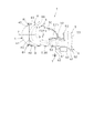
以下、この発明にかかる車両用灯具の実施形態(実施例)の2例を図面に基づいて詳細に説明する。なお、この実施形態によりこの発明が限定されるものではない。図1、図6において、破線矢印は、空気の流れを示すものである。また、図1、図6において、光源、投影レンズ、ファンのハッチングを省略してある。この明細書において、前、後、上、下、左、右とは、この発明にかかる車両用灯具を車両に装備した際の前、後、上、下、左、右である。 Hereinafter, two examples of the embodiment (example) of the vehicle lamp according to the present invention will be described in detail based on the drawings. The present invention is not limited by this embodiment. In FIG. 1 and FIG. 6, broken arrows indicate the flow of air. Further, hatching of the light source, the projection lens, and the fan is omitted in FIGS. 1 and 6. In this specification, front, back, top, bottom, left and right are front, back, top, bottom, left and right when the vehicle lamp according to the present invention is mounted on a vehicle.
(実施形態1の構成の説明)
図1〜図5は、この発明にかかる車両用灯具の実施形態1を示す。以下、この実施形態1における車両用灯具の構成について説明する。この例は、たとえば、自動車用前照灯のヘッドランプについて説明する。
(Description of Configuration of Embodiment 1)
1 to 5 show a first embodiment of a vehicular lamp according to the present invention. Hereinafter, the configuration of the vehicle lamp in the first embodiment will be described. This example describes, for example, a headlamp of a motor vehicle headlamp.
(車両用灯具1の説明)
図において、符号1は、この実施形態1における車両用灯具である。前記車両用灯具1は、車両(図示せず)の前部の左右両側にそれぞれ搭載されている。前記車両用灯具1は、ランプハウジング(図示せず)と、ランプレンズ(図示せず)と、光源2と、リフレクタ3と、投影レンズ4と、ヒートシンク部材5と、ファン6と、ガイド部材7と、ホルダ部材8と、シェード9と、を備える。前記光源2および前記リフレクタ3および前記投影レンズ4および前記ファン6および前記ガイド部材7および前記ホルダ部材8および前記シェード9は、取付部材と兼用の前記ヒートシンク部材5にそれぞれ取り付けられている。
(Description of the vehicle lamp 1)
In the figure, the code |
前記ランプハウジングおよび前記ランプレンズ(たとえば、素通しのアウターレンズなど)は、灯室(図示せず)を画成する。前記光源2および前記リフレクタ3および前記投影レンズ4および前記ヒートシンク部材5および前記ファン6および前記ガイド部材7および前記ホルダ部材8および前記シェード9は、プロジェクタタイプのランプユニットを構成する。前記ランプユニット2、3、4、5、6、7、8、9は、ロービーム配光パターン(図示せず)を前記車両の前方に照射するランプユニットである。
The lamp housing and the lamp lens (e.g., a transparent outer lens, etc.) define a lamp chamber (not shown). The
前記ランプユニット2、3、4、5、6、7、8、9は、前記灯室内に配置されていて、かつ、上下方向用光軸調整機構(図示せず)および左右方向用光軸調整機構(図示せず)を介して前記ランプハウジングに取り付けられている。なお、前記灯室内には、図示されていないが、ハイビーム照射ランプユニット、ADB照射ランプユニット、フォグランプ、コーナリングランプ、クリアランスランプ、ターンシグナルランプ、オーバーヘッドサインランプ、デイタイムランニングランプなどの他のランプユニットが配置されている場合がある。
The
(光源2の説明)
前記光源2は、この例では、半導体型光源であって、LED、OELまたはOLED(有機EL)などの自発光半導体型光源を使用する。前記光源2は、光を放射する発光面を有する発光部と、基板部と、から構成されている。たとえば、前記光源2は、前記発光部としての発光チップ(LEDチップ)を封止樹脂部材で封止したパッケージ(LEDパッケージ)から構成されている。前記パッケージは、前記基板に実装されている。前記基板に取り付けられているコネクタ(図示せず)を介して前記発光チップには、電源(バッテリー)からの電流が供給される。
(Description of light source 2)
The
(リフレクタ3の説明)
前記リフレクタ3は、たとえば、樹脂部材や金属製ダイカスト(アルミダイカスト)などの耐熱性が高くかつ光不透過性の材料からなる。前記リフレクタ3は、前側部分および下側部分が開口し、かつ、後側部分および上側部分および左右両側部分が閉塞した中空形状をなす。前記リフレクタ3の閉塞部分の凹内面には、回転楕円面(楕円)を基本(基調)とした自由曲面からなる反射面30が設けられている。
(Description of reflector 3)
The
前記反射面30は、自由曲面から構成されている。前記反射面30は、第1焦点F1および第2焦点(もしくは第2焦線)F2と、前記第1焦点F1と前記第2焦点F2とを結ぶ光軸(図示せず)と、を有する。前記第1焦点F1は、前記第2焦点F2よりも下位に位置する。このために、前記光軸は、前記光源2から前記投影レンズ4にかけて上方向に傾斜している。前記反射面30は、前記光源2からの光を反射光として前記投影レンズ4側に反射させるものである。
The reflecting
(投影レンズ4の説明)
前記投影レンズ4は、たとえば、PC材、PMMA材、PCO材などの樹脂製のレンズからなるものである。すなわち、前記光源2から放射される光は、高い熱を持たないので、前記投影レンズ4として樹脂製のレンズを使用することができる。
(Description of the projection lens 4)
The
前記投影レンズ4は、前記リフレクタ3および前記シェード9と共に、前記光源2からの光を所定の配光パターンこの例では前記ロービーム配光パターンとして、外部すなわち車両の前方に照射(投影)する光学部材を構成するものである。前記投影レンズ4は、後面の平面の入射面40と、前面の非球面の出射面41と、フランジ部42と、から構成されている。
The
前記投影レンズ4の後側焦点(物空間側の焦点面であるメリジオナル像面)F3は、前記反射面30の前記第2焦点F2に一致もしくはほぼ一致する。前記投影レンズ4の光軸(レンズ軸)Zは、水平もしくはほぼ水平をなす。このために、前記投影レンズ4の前記光軸Zは、前記反射面30の前記光軸と、前記後側焦点F3、前記第2焦点もしくはその近傍において交差する。
A back focal point (meridional image plane which is a focal plane on the object space side) F3 of the
(ヒートシンク部材5の説明)
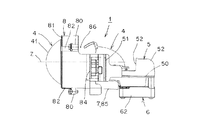
前記ヒートシンク部材5は、熱伝達(熱伝導)が良い部材(熱抵抗が小さい部材)から構成されている。前記ヒートシンク部材5は、水平取付板部50と、垂直取付板部51と、垂直板部52と、複数枚のフィン部53と、から一体に構成されている。
(Description of the heat sink member 5)
The
前記水平取付板部50の一端(後端)と前記垂直板部52の一端(下端)とが、一体に接続されている。前記水平取付板部50の一面(下面)と前記垂直板部52の一面(後面)とには、複数枚の前記フィン部53が一体に接続されている。この結果、複数枚の前記フィン部53は、前記水平取付板部50より下方に位置する前端と、前記垂直板部52より後方に位置する上端と、下端と、後端と、がそれぞれ開口している。
One end (rear end) of the horizontal
複数枚の前記フィン部53は、左右方向に等間隔もしくはほぼ等間隔に配置されていて、かつ、前後方向(前記光軸Z方向)に延設されている。複数枚の前記フィン部53は、前記水平取付板部50に対応する水平部と、前記垂直板部52に対応する垂直部と、からなる側面視L字形状をなす。
The plurality of
前記水平取付板部50の他面(上面)には、前記光源2と前記リフレクタ3とが取り付けられている。前記水平取付板部50の一面には、前記ファン6が取り付けられている。前記垂直取付板部51の一面(前面)には、前記投影レンズ4が前記ホルダ部材8を介して前記ガイド部材7と共に取り付けられている。前記水平取付板部50もしくは前記垂直取付板部51のうち少なくともいずれか一方には、前記シェード9が取り付けられている。
The
(ファン6の説明)
前記ファン6は、空気(図1中の破線矢印を参照)を軸方向の一方(下方)から吸い込んで軸方向の他方(上方)に吐き出す軸流タイプのファンである。前記ファン6は、モータ(図示せず)と、前記モータにより回転させられる羽根車60と、前記羽根車60に設けられているブレード61と、前記モータおよび前記羽根車60および前記ブレード61を覆うケーシング62と、から構成されている。
(Description of fan 6)
The
前記ファン6は、空気の排出側(吹き出し側)が複数枚の前記フィン部53の開口下端に対向していて、空気を下側から上側に複数枚の前記フィン部53の前記開口下端に向けて強制的に送る。また、前記ファン6は、前記光源2よりも後側(前記投影レンズ4と反対側)に位置する。
The
(ガイド部材7の説明)
前記ガイド部材7は、前記ファン6から強制的に送られてくる空気が複数枚の前記フィン部53の間を通るようにガイドするものである。前記ガイド部材7は、複数枚の前記フィン部53の開口端のうち、空気が通る方向と平行もしくはほぼ平行な開口端、この例では、前記開口下端を閉塞するものである。この例の前記ガイド部材7は、複数枚の前記フィン部53の空気が通る方向と平行もしくはほぼ平行な前記開口下端のうち、少なくとも、前記光源2と対応する前記開口下端を閉塞する。すなわち、前記ガイド部材7は、少なくとも、前記光源2の真下もしくはほぼ真下まで位置する。
(Description of the guide member 7)
The guide member 7 guides air forcedly sent from the
前記ガイド部材7の一端(後端)と前記ファン6の前記ケーシング62との間の寸法Tは、複数枚の前記フィン部53の間の寸法よりも小さい。前記ガイド部材7は、複数枚の前記フィン部53の間を通った空気が前記光学部材としての前記投影レンズ4側に送られるように、前記ヒートシンク部材5と前記投影レンズ4との間にも配置されている。すなわち、この例の前記ガイド部材7は、前記投影レンズ4が保持されていて、かつ、前記ヒートシンク部材5に取り付けられている前記ホルダ部材8と一体構造をなすものである。
The dimension T between one end (rear end) of the guide member 7 and the
(ホルダ部材8の説明)
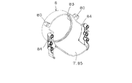
前記ホルダ部材8は、円筒形状をなす。前記ホルダ部材8の一端開口部(後端開口部)の外周面には、複数個この例では3個のボス部80が一体に設けられている。前記ボス部80には、リム81の複数本この例では3本の脚部82がスクリューにより取り付けられている。前記リム81は、円環形状をなし、3本の前記脚部82が一体に設けられている。
(Description of holder member 8)
The
前記ホルダ部材8の他端開口部(前端開口部)の内周面には、凸部83が一体に設けられている。前記凸部83と前記リム81との間には、前記投影レンズ4の前記フランジ部42が挟み込まれている。これにより、前記投影レンズ4は、前記ホルダ部材8に取り付けられて保持されている。
A
前記ホルダ部材8の一端開口部(後端開口部)の外周面の左右両側には、垂直取付部84が一体に設けられている。前記垂直取付部84は、前記ヒートシンク部材5の前記垂直取付部51に取り付けられている。この結果、前記光学部材としての前記投影レンズ4は、前記ホルダ部材8を介して、前記ヒートシンク部材5に取り付けられることとなる。
前記ホルダ部材8の一端開口部(後端開口部)の下部85が後方に延設されている。前記下部85は、前記ガイド部材7と一体構造をなすものである。この結果、前記ガイド部材7は、前記光源2と対応する前記ヒートシンク部材5の前記開口下端から前記投影レンズ4までの間に配置されていることとなる。すなわち、前記ガイド部材7は、少なくとも、前記光源2の真下もしくはほぼ真下まで位置する。
A lower portion 85 of one end opening (rear end opening) of the
前記ホルダ部材8の一端開口部(後端開口部)の上部と前記リフレクタ3の前端部との間には、開口部86が形成されている。
An
(シェード9の説明)
前記シェード9は、前記反射面30からの反射光の一部をカットオフして前記ロービーム配光パターンを形成するものである。前記シェード9には、前記ロービーム配光パターンのカットオフライン(図示せず)を形成するエッジが設けられている。前記エッジは、前記第2焦点F2、前記後側焦点F3もしくはその近傍に位置する。
(Description of shade 9)
The
(実施形態1の作用の説明)
この実施形態1における車両用灯具1は、以上のごとき構成からなり、以下、その作用について説明する。
(Description of the operation of the first embodiment)
The
光源2を点灯発光させる。すると、光源2から放射された光は、リフレクタ3の反射面30で投影レンズ4側に反射する。その反射光の一部は、シェード9によりカットオフされる。シェード9によりカットオフされなかった反射光の残りは、投影レンズ4の入射面40から投影レンズ4中に入射する。その入射光は、投影レンズ4の出射面41から、ロービーム配光パターンとして、外部すなわち車両の前方に照射される。
The
ここで、光源2において発生する熱の大部分は、ヒートシンク部材5の水平取付板部50および垂直板部52を介して複数枚のフィン部53に伝わる。一方、ファン6のモータを駆動させると、羽根車60とブレード61とが回転する。これにより、空気が、強制的に、ファン6の下側から吸い込まれて上側、すなわち、ヒートシンク部材5の複数枚のフィン部53の開口下端側に吐き出される。
Here, most of the heat generated in the
ファン6から強制的に突出されて送られてきた空気は、複数枚のフィン部53の開口下端から複数枚のフィン部53の間に下側から上側に進む。その空気の一部は、ヒートシンク部材5の水平取付板部50の下面に当たって前方と後方とに分かれて流れる。
The air forcedly protruded and sent from the
前方に分かれた空気は、水平取付板部50と共にダクトと同様な作用をするガイド部材7により、複数枚のフィン部53の間を後側から前側に水平に通り、しかも、複数枚のフィン部53の間から漏れてしまうのを防がれている。
The air divided forward travels horizontally between the plurality of
複数枚のフィン部53の間を後側から前側に水平に通って複数枚のフィン部53の開口前端から出てきた空気は、ガイド部材7と一体構造のホルダ部材8の下部85のガイド作用により、投影レンズ4の入射面40側まで進む。
The air passing horizontally from the rear side to the front side between the plurality of
投影レンズ4の入射面40側まで進んだ空気は、リフレクタ3および投影レンズ4およびガイド部材7およびホルダ部材8により囲まれた空間内を下側から上側に進み、リフレクタ3とホルダ部材8との間の開口部86から、プロジェクタタイプのランプユニット2、3、4、5、6、7、8、9の空間外(灯室内)に排出する。
The air having traveled to the
一方、後方に分かれた空気は、水平取付板部50に沿って、複数枚のフィン部53の間を前側から後側に水平に通る。その空気は、複数枚のフィン部53の開口下端から複数枚のフィン部53の間に下側から上側に進む空気と合流する。その合流した空気は、垂直板部52に沿って、複数枚のフィン部53の間に下側から上側に進んで、複数枚のフィン部53の開口上端から灯室内に排出する。
On the other hand, the air divided rearward passes horizontally along the horizontal
これにより、光源2において発生する熱は、ヒートシンク部材5およびファン6およびガイド部材7の作用により、効率良く灯室内側に排出される。また、リフレクタ3および投影レンズ4およびガイド部材7およびホルダ部材8により囲まれた空間内にこもる熱は、ファン6およびガイド部材7の作用により、開口部86から灯室内側に効率良く排出される。
Thereby, the heat generated in the
(実施形態1の効果の説明)
この実施形態1における車両用灯具1は、以上のごとき構成および作用からなり、以下、その効果について説明する。
(Description of the effect of Embodiment 1)
The
この実施形態1における車両用灯具1は、ガイド部材7により、ファン6から強制的に送られてくる空気がヒートシンク部材5の複数枚のフィン部53の間を通るようにガイドされる。このために、ファン6から強制的に送られてくる空気の大部分が複数枚のフィン部53の間を通り、しかも、ファン6から強制的に送られてくる空気が複数枚のフィン部53の間から漏れてしまうのを防ぐことができる。この結果、ヒートシンク部材5による十分な放熱効果が得られる。
The
この実施形態1における車両用灯具1は、ガイド部材7が、複数枚のフィン部53の開口端のうち、空気が通る方向と平行もしくはほぼ平行な開口端、この例では、開口下端を閉塞するものである。このために、ファン6から強制的に送られてくる空気が複数枚のフィン部53の間から開口下端を経て外部に漏れてしまうのを確実に防ぐことができる。この結果、ヒートシンク部材5によるさらなる十分な放熱効果が得られる。
In the
この実施形態1における車両用灯具1は、ガイド部材7が、複数枚のフィン部53の空気が通る方向と平行もしくはほぼ平行な開口下端のうち、少なくとも、光源2と対応する開口下端を閉塞する。すなわち、ガイド部材7は、少なくとも、光源2の真下もしくはほぼ真下まで位置する。このために、光源2において発生する熱を水平取付板部50を経て複数枚のフィン部53により外部に確実に排出することができる。この結果、ヒートシンク部材5による十分な放熱効果が得られる。
In the
この実施形態1における車両用灯具1は、ガイド部材7が、複数枚のフィン部53の間を通った空気が光学部材としての投影レンズ4側に送られるように、ヒートシンク部材5と投影レンズ4との間にも配置されている。このために、リフレクタ3および投影レンズ4およびガイド部材7およびホルダ部材8により囲まれた空間内にこもる熱を、ファン6およびガイド部材7の作用により、開口部86から灯室内側に効率良く排出することができる。この結果、光源2において発生する熱の放熱効果が得られる。
In the
この実施形態1における車両用灯具1は、ガイド部材7とホルダ部材8とが一体構造をなすものである。このために、部品点数や組付工程数などを軽減することができ、その分、製造コストを安価にすることができる。
In the
この実施形態1における車両用灯具1は、ガイド部材7の一端(後端)とファン6のケーシング62との間の寸法Tが、複数枚のフィン部53の間の寸法よりも小さい。このために、ガイド部材7が十分なガイド作用をする。この結果、光源2において発生する熱の放熱効果が得られる。
In the
(実施形態2の構成、作用、効果の説明)
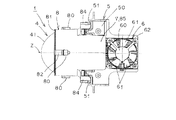
図6は、この発明にかかる車両用灯具の実施形態2を示す。以下、この実施形態2にかかる車両用灯具について説明する。
(Description of the configuration, operation, and effects of the second embodiment)
FIG. 6 shows a second embodiment of the vehicle lamp according to the present invention. Hereinafter, the vehicle lamp according to the second embodiment will be described.
前記の実施形態1の車両用灯具1は、図1に示すように、ファン6を、ヒートシンク部材5の複数枚のフィン部53の開口下端に向けて、かつ、光源2よりも後側(投影レンズ4と反対側)に位置させ、風を下側から上側に強制的に送るものである。
In the
これに対して、この実施形態2にかかる車両用灯具100は、ファン6を、ヒートシンク部材5の複数枚のフィン部53の開口後端に向けて位置させて、風を後側から前側に強制的に送るものである。
On the other hand, in the
この実施形態2にかかる車両用灯具100は、上記のごとき構成からなるので、前記の実施形態1の車両用灯具1とほぼ同様の作用、効果を達成することができる。なお、図6中の二点鎖線にて示すように、前記の実施形態1の車両用灯具1のファン6が位置していたヒートシンク部材5の複数枚のフィン部53の開口下端に、前記の実施形態1のガイド部材7を後方に延長したガイド部材70を設けても良い。
The
(変形例の説明)
以下、この発明にかかる車両用灯具の変形例について説明する。この変形例にかかる車両用灯具は、前記の実施形態1、2にかかる車両用灯具1、100のガイド部材7の一部分が円筒形状をなすものである。すなわち、前記の実施形態1、2にかかる車両用灯具1、100の円筒形状をなすホルダ部材8を、ガイド部材7の一部分の円筒形状の部分とするものである。
(Description of modification)
Hereinafter, modifications of the vehicle lamp according to the present invention will be described. In the vehicle lamp according to this modification, a part of the guide member 7 of the
この変形例にかかる車両用灯具は、ガイド部材7の一部分(ホルダ部材8)が円筒形状をなすものであるから、空気を円筒形状に沿って上方に導き易い。これにより、放熱効果が向上される。なお、実施形態1、2にかかる車両用灯具1、100、変形例にかかる車両用灯具においては、正面視円形の投影レンズ4を使用するので、ガイド部材7の一部分を円筒形状とするものである。ところが、レンズの正面視形状が円形以外の形状であれば、ガイド部材7の一部分の筒形状の形状も変わる。たとえば、レンズの正面視形状が矩形形状であれば、ガイド部材7の一部分は、矩形筒形状をなすものである。
In the vehicle lamp according to this modification, since a part of the guide member 7 (holder member 8) has a cylindrical shape, air can be easily guided upward along the cylindrical shape. Thereby, the heat dissipation effect is improved. In the
(実施形態1、2以外の例の説明)
なお、この実施形態1、2においては、プロジェクタタイプのランプユニット2、3、4、5、6、7、8、9について説明するものである。ところが、この発明においては、プロジェクタタイプのランプユニット2、3、4、5、6、7、8、9以外のランプユニット、たとえば、レンズ直射タイプのランプユニット、リフレクタタイプのランプユニットであっても良い。
(Description of Examples Other than
In the first and second embodiments, projector-
また、この実施形態1、2においては、シェード9として固定シェードを使用するものである。ところが、この発明においては、シェード9として可動シェードを使用しても良い。この場合、配光パターンは、ロービーム配光パターンとハイビーム配光パターンとが得られる。
In the first and second embodiments, a fixed shade is used as the
1、100 車両用灯具
2 光源
3 リフレクタ
30 反射面
4 投影レンズ
40 入射面
41 出射面
42 フランジ部
5 ヒートシンク部材
50 水平取付板部
51 垂直取付板部
52 垂直板部
53 フィン部
6 ファン
60 羽根車
61 ブレード
62 ケーシング
7、70 ガイド部材
8 ホルダ部材
80 ボス部
81 リム
82 脚部
83 凸部
84 垂直取付部
85 下部
86 開口部
9 シェード
F1 第1焦点
F2 第2焦点
F3 後側焦点
Z 光軸
DESCRIPTION OF
Claims (4)
前記光源が取り付けられている取付部と、複数枚のフィン部と、から構成されているヒートシンク部材と、
前記光源からの光を所定の配光パターンとして外部に照射する投影レンズを含む光学部材と、
前記投影レンズを保持するホルダ部材と、
複数枚の前記フィン部の間に空気を強制的に送るファンと、
前記ファンから強制的に送られてくる空気が複数枚の前記フィン部の間を通るようにガイドするガイド部材と、
を備え、
前記ホルダ部材は、車両搭載状態における後端に開口部を有し、当該開口部の下部に後方に向けて延設された延設部分を有し、
前記ガイド部材は、前記延設部分と一体構造をなし、複数枚の前記フィン部の開口端のうち前端から出てきた空気が前記投影レンズの入射面まで進むようにガイドする、
ことを特徴とする車両用灯具。 Light source,
A heat sink member including an attachment portion to which the light source is attached, and a plurality of fin portions;
An optical member including a projection lens for emitting light from the light source to the outside as a predetermined light distribution pattern;
A holder member for holding the projection lens;
A fan forcibly sending air between the plurality of fins;
A guide member for guiding air forcedly sent from the fan to pass between the plurality of fin portions;
Bei to give a,
The holder member has an opening at a rear end in a vehicle mounted state, and has an extending portion extending rearward at a lower portion of the opening.
The guide member has an integral structure with the extended portion, and guides air coming from the front end of the open ends of the plurality of fins to be directed to the incident surface of the projection lens.
A vehicle lamp characterized in that.
ことを特徴とする請求項1に記載の車両用灯具。 The guide member closes an open end parallel to or substantially parallel to a direction in which air passes, among the open ends of the plurality of fins.
The vehicle lamp according to claim 1, characterized in that:
ことを特徴とする請求項2に記載の車両用灯具。 The guide member closes at least the open end corresponding to the light source among the open ends parallel or substantially parallel to the air passing direction of the plurality of fins.
The vehicle lamp according to claim 2, characterized in that:
ことを特徴とする請求項1〜3のいずれか1項に記載の車両用灯具。 A portion of the guide member has a tubular shape,
The vehicle lamp according to any one of claims 1 to 3 , characterized in that.
Priority Applications (1)
| Application Number | Priority Date | Filing Date | Title |
|---|---|---|---|
| JP2014152044A JP6520003B2 (en) | 2014-07-25 | 2014-07-25 | Vehicle lamp |
Applications Claiming Priority (1)
| Application Number | Priority Date | Filing Date | Title |
|---|---|---|---|
| JP2014152044A JP6520003B2 (en) | 2014-07-25 | 2014-07-25 | Vehicle lamp |
Publications (2)
| Publication Number | Publication Date |
|---|---|
| JP2016031777A JP2016031777A (en) | 2016-03-07 |
| JP6520003B2 true JP6520003B2 (en) | 2019-05-29 |
Family
ID=55442071
Family Applications (1)
| Application Number | Title | Priority Date | Filing Date |
|---|---|---|---|
| JP2014152044A Active JP6520003B2 (en) | 2014-07-25 | 2014-07-25 | Vehicle lamp |
Country Status (1)
| Country | Link |
|---|---|
| JP (1) | JP6520003B2 (en) |
Families Citing this family (12)
| Publication number | Priority date | Publication date | Assignee | Title |
|---|---|---|---|---|
| JP6741467B2 (en) * | 2016-05-12 | 2020-08-19 | 株式会社小糸製作所 | Vehicle lighting |
| JP6674851B2 (en) * | 2016-06-30 | 2020-04-01 | スタンレー電気株式会社 | Vehicle lighting |
| JP2018014285A (en) * | 2016-07-22 | 2018-01-25 | スタンレー電気株式会社 | Vehicular lighting fixture |
| KR20180065661A (en) * | 2016-12-08 | 2018-06-18 | 엘지이노텍 주식회사 | Light unit and Lamp unit for automobile of using the same |
| DE102016124763A1 (en) * | 2016-12-19 | 2018-06-21 | HELLA GmbH & Co. KGaA | Lighting device for vehicles |
| JP6985801B2 (en) * | 2017-02-23 | 2021-12-22 | スタンレー電気株式会社 | Lighting equipment |
| JP6938958B2 (en) * | 2017-02-27 | 2021-09-22 | 市光工業株式会社 | Vehicle headlights |
| CN108662551B (en) * | 2018-05-14 | 2020-03-13 | 安徽卡澜特车灯科技有限公司 | Projection type double-light lens |
| JPWO2019221007A1 (en) * | 2018-05-18 | 2021-07-01 | 株式会社小糸製作所 | Imaging device and lamp device |
| JP7321701B2 (en) * | 2018-12-07 | 2023-08-07 | 株式会社小糸製作所 | lighting unit |
| CN211551488U (en) * | 2019-12-30 | 2020-09-22 | 深圳市绎立锐光科技开发有限公司 | Lighting device and vehicle lamp |
| JP7459643B2 (en) | 2020-04-30 | 2024-04-02 | 市光工業株式会社 | Vehicle lighting fixtures |
Family Cites Families (5)
| Publication number | Priority date | Publication date | Assignee | Title |
|---|---|---|---|---|
| US7329033B2 (en) * | 2005-10-25 | 2008-02-12 | Visteon Global Technologies, Inc. | Convectively cooled headlamp assembly |
| JP4458067B2 (en) * | 2006-05-17 | 2010-04-28 | 市光工業株式会社 | Vehicle lighting |
| JP5160992B2 (en) * | 2008-07-24 | 2013-03-13 | 株式会社小糸製作所 | Vehicle lighting |
| KR101796115B1 (en) * | 2010-10-13 | 2017-11-13 | 삼성전자 주식회사 | Head lamp assembly and vehicle having the same |
| JP2014120344A (en) * | 2012-12-17 | 2014-06-30 | Ichikoh Ind Ltd | Vehicle lighting tool |
-
2014
- 2014-07-25 JP JP2014152044A patent/JP6520003B2/en active Active
Also Published As
| Publication number | Publication date |
|---|---|
| JP2016031777A (en) | 2016-03-07 |
Similar Documents
| Publication | Publication Date | Title |
|---|---|---|
| JP6520003B2 (en) | Vehicle lamp | |
| JP6061638B2 (en) | Vehicle lighting | |
| US7824088B2 (en) | Vehicle lighting apparatus | |
| JP6028487B2 (en) | Vehicle lighting | |
| CN109958962B (en) | Lamp unit | |
| JP4752626B2 (en) | Vehicle lighting | |
| JP2008041558A (en) | Headlamp for vehicle | |
| CN108243618B (en) | Vehicle headlamp | |
| TWM536321U (en) | Illumination structure | |
| JP2013243068A (en) | Vehicle headlight | |
| JP2013152852A (en) | Vehicular lamp | |
| CN116157626A (en) | Lamp for vehicle | |
| JP6252110B2 (en) | Vehicle lighting | |
| JP2017208208A (en) | Lamp | |
| JP6078276B2 (en) | Lamp unit | |
| JP2017120736A (en) | Headlight and movable body | |
| JP6439341B2 (en) | Vehicle lighting | |
| JP2011198702A (en) | Vehicular headlight | |
| TWI642568B (en) | Illumination structure and light distribution method thereof | |
| JP5110578B2 (en) | Vehicle lighting | |
| JP6171172B2 (en) | Vehicle lighting | |
| JP6435903B2 (en) | Vehicle headlamp | |
| JP2020095876A (en) | Vehicular lighting fixture | |
| JP6455004B2 (en) | Vehicle lighting | |
| JP6464678B2 (en) | Vehicle headlamp |
Legal Events
| Date | Code | Title | Description |
|---|---|---|---|
| A621 | Written request for application examination |
Free format text: JAPANESE INTERMEDIATE CODE: A621 Effective date: 20170724 |
|
| A131 | Notification of reasons for refusal |
Free format text: JAPANESE INTERMEDIATE CODE: A131 Effective date: 20180814 |
|
| A977 | Report on retrieval |
Free format text: JAPANESE INTERMEDIATE CODE: A971007 Effective date: 20180815 |
|
| A521 | Request for written amendment filed |
Free format text: JAPANESE INTERMEDIATE CODE: A523 Effective date: 20181011 |
|
| TRDD | Decision of grant or rejection written | ||
| A01 | Written decision to grant a patent or to grant a registration (utility model) |
Free format text: JAPANESE INTERMEDIATE CODE: A01 Effective date: 20190402 |
|
| A61 | First payment of annual fees (during grant procedure) |
Free format text: JAPANESE INTERMEDIATE CODE: A61 Effective date: 20190415 |
|
| R150 | Certificate of patent or registration of utility model |
Ref document number: 6520003 Country of ref document: JP Free format text: JAPANESE INTERMEDIATE CODE: R150 |
|
| R250 | Receipt of annual fees |
Free format text: JAPANESE INTERMEDIATE CODE: R250 |
|
| R250 | Receipt of annual fees |
Free format text: JAPANESE INTERMEDIATE CODE: R250 |