EP3553331A1 - Verbindungsvorrichtung, die zwischen mindestens zwei teilen schwenkbar ist, luftfahrzeug, das eine abdeckung umfasst, die mit dieser schwenkbaren verbindungsvorrichtung ausgestattet ist - Google Patents
Verbindungsvorrichtung, die zwischen mindestens zwei teilen schwenkbar ist, luftfahrzeug, das eine abdeckung umfasst, die mit dieser schwenkbaren verbindungsvorrichtung ausgestattet ist Download PDFInfo
- Publication number
- EP3553331A1 EP3553331A1 EP19163514.3A EP19163514A EP3553331A1 EP 3553331 A1 EP3553331 A1 EP 3553331A1 EP 19163514 A EP19163514 A EP 19163514A EP 3553331 A1 EP3553331 A1 EP 3553331A1
- Authority
- EP
- European Patent Office
- Prior art keywords
- extension
- guide ring
- leg
- cylindrical axis
- locking
- Prior art date
- Legal status (The legal status is an assumption and is not a legal conclusion. Google has not performed a legal analysis and makes no representation as to the accuracy of the status listed.)
- Granted
Links
Images
Classifications
-
- F—MECHANICAL ENGINEERING; LIGHTING; HEATING; WEAPONS; BLASTING
- F16—ENGINEERING ELEMENTS AND UNITS; GENERAL MEASURES FOR PRODUCING AND MAINTAINING EFFECTIVE FUNCTIONING OF MACHINES OR INSTALLATIONS; THERMAL INSULATION IN GENERAL
- F16C—SHAFTS; FLEXIBLE SHAFTS; ELEMENTS OR CRANKSHAFT MECHANISMS; ROTARY BODIES OTHER THAN GEARING ELEMENTS; BEARINGS
- F16C11/00—Pivots; Pivotal connections
- F16C11/04—Pivotal connections
-
- B—PERFORMING OPERATIONS; TRANSPORTING
- B64—AIRCRAFT; AVIATION; COSMONAUTICS
- B64D—EQUIPMENT FOR FITTING IN OR TO AIRCRAFT; FLIGHT SUITS; PARACHUTES; ARRANGEMENT OR MOUNTING OF POWER PLANTS OR PROPULSION TRANSMISSIONS IN AIRCRAFT
- B64D29/00—Power-plant nacelles, fairings or cowlings
- B64D29/06—Attaching of nacelles, fairings or cowlings
-
- B—PERFORMING OPERATIONS; TRANSPORTING
- B64—AIRCRAFT; AVIATION; COSMONAUTICS
- B64D—EQUIPMENT FOR FITTING IN OR TO AIRCRAFT; FLIGHT SUITS; PARACHUTES; ARRANGEMENT OR MOUNTING OF POWER PLANTS OR PROPULSION TRANSMISSIONS IN AIRCRAFT
- B64D29/00—Power-plant nacelles, fairings or cowlings
- B64D29/08—Inspection panels for power plants
-
- F—MECHANICAL ENGINEERING; LIGHTING; HEATING; WEAPONS; BLASTING
- F16—ENGINEERING ELEMENTS AND UNITS; GENERAL MEASURES FOR PRODUCING AND MAINTAINING EFFECTIVE FUNCTIONING OF MACHINES OR INSTALLATIONS; THERMAL INSULATION IN GENERAL
- F16C—SHAFTS; FLEXIBLE SHAFTS; ELEMENTS OR CRANKSHAFT MECHANISMS; ROTARY BODIES OTHER THAN GEARING ELEMENTS; BEARINGS
- F16C11/00—Pivots; Pivotal connections
- F16C11/04—Pivotal connections
- F16C11/10—Arrangements for locking
-
- E—FIXED CONSTRUCTIONS
- E05—LOCKS; KEYS; WINDOW OR DOOR FITTINGS; SAFES
- E05D—HINGES OR SUSPENSION DEVICES FOR DOORS, WINDOWS OR WINGS
- E05D5/00—Construction of single parts, e.g. the parts for attachment
- E05D5/10—Pins, sockets or sleeves; Removable pins
- E05D5/12—Securing pins in sockets, movably or not
-
- F—MECHANICAL ENGINEERING; LIGHTING; HEATING; WEAPONS; BLASTING
- F16—ENGINEERING ELEMENTS AND UNITS; GENERAL MEASURES FOR PRODUCING AND MAINTAINING EFFECTIVE FUNCTIONING OF MACHINES OR INSTALLATIONS; THERMAL INSULATION IN GENERAL
- F16C—SHAFTS; FLEXIBLE SHAFTS; ELEMENTS OR CRANKSHAFT MECHANISMS; ROTARY BODIES OTHER THAN GEARING ELEMENTS; BEARINGS
- F16C2326/00—Articles relating to transporting
- F16C2326/43—Aeroplanes; Helicopters
Definitions
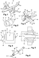
- an aircraft 10 comprises several power units 12 which are positioned under the wing 14 of the aircraft 10.
- An engine assembly 12 comprises a motor 16, a nacelle 18 positioned around the engine 16 and a mast 20 which provides the connection between the engine 16 and the rest of the aircraft 10, in particular the wing 14.
- the nacelle 18 comprises at least one cover 22 connected to the rest of the nacelle 18 by a hinge 24 allowing the cover 22 to pivot about a pivot axis A24 between an open position (visible on the figure 2 ) and a closed position (visible on the figure 1 ).
- the hinge 24 has several pivoting connection devices 26 distributed along the pivot axis A24.
- Guide rings may be interposed between the cylindrical axis 32 and the legs 28.1, 28.2 of the yoke 28 and between the cylindrical axis 32 and the arm 30.
- the pivoting connection device 26 also comprises first and second stops 34, 36, positioned on either side of the legs 28.1, 28.2 of the yoke 28, for immobilizing in translation the cylindrical axis 32 relative to the branches 28.1, 28.2 in a direction parallel to the pivot axis A24.
- the cylindrical axis 32 has at a first end a head 38 which forms the first stop 34 and which is configured to bear against the outer face F28.1 of the first leg 28.1 of the yoke 28.
- the second stop 36 is in the form of a cotter pin 40 which passes through the cylindrical axis 32 and which is configured to bear against the outer face F28.2 of the second leg 28.2 of the yoke 28.
- This first embodiment requires that both sides of the yoke 28 are accessible to assemble the pivotal connecting device, the cylindrical axis 32 being introduced from a first side of the yoke 28, the cotter pin being put in place since a second side of the coping 28.
- Screwing or unscrewing the screw 46 causes the insert 44 and the head 46.1 of the screw 46 to move towards or away from each other.
- the second end of the tubular body 42 is not expanded radially.
- the second end of the tubular body 42 is expanded radially.
- the insert 44 and the head 46.1 of the screw 46 being in the separated state, the connecting system is inserted into the bores of the branches 28.1, 28.2 of the yoke 28 and the arm 30 for a second time. first side of the yoke 28.
- the connecting system is inserted, the head 46.1 of the screw 46 and the insert 44 are brought together by screwing the screw 46, from the first side of the yoke 28, so as to provoke the expansion of the second end of the tubular body 42.
- the flange 42.1 of the tubular body 42 forms a first stop for immobilizing the tubular body 42 in a first direction.
- Expansion of the second end of the tubular body forms a second stop for immobilizing the tubular body 42 in a second direction, opposite to the first direction.
- the friction between the tubular body 42 and the second leg 28.2 of the yoke 28, due to the radial expansion of the second end of the tubular body also contribute to the immobilization of the tubular body 42 relative to the second leg 28.2.
- This second embodiment makes it possible to assemble the pivoting connecting device from a single side of the yoke 28.
- this second embodiment induces significant radial loads at the bore of one of the two branches 28.2 of the yoke 28 due to the expansion of the second end of the tubular body 42.
- the present invention aims to overcome the disadvantages of the prior art.
- the invention relates to a pivoting connecting device connecting at least two parts as claimed in claim 1.
- the pivoting connecting device can be assembled from one side of the yoke.
- the pivoting connection device does not induce any radial load in the bore of one of the branches, unlike the second embodiment of the prior art.
- none of the other parts of the pivotal connection device is subjected to constraints in the locked state.
- a pivoting connecting device 50 connecting at least first and second parts 52 and 54.
- the first part 52 is a hood of an aircraft nacelle and the second part 54 is a nacelle of aircraft.
- a longitudinal direction is a direction parallel to the pivot axis A64.
- a radial direction is perpendicular to the pivot axis A64.
- a longitudinal plane is a plane that passes through the pivot axis A64.
- a transverse plane is a plane perpendicular to the pivot axis A64.
- each leg 58 (or 60) includes an inner face FI58 (or FI60), facing the other leg 60 (or 58), and an outer face FE58 (or FE60) opposite the inner face FI58 (or F60).
- the inner faces FI58, FI60 and the outer faces FE58, FE60 are parallel to each other and positioned in transverse planes.
- Each leg 58 (or 60) comprises a bore 66 (or 68) which opens at the inner face FI58 (or FI60) and the outer face FE58 (or FE60), the bore 66 (or 68) having an axis of revolution perpendicular to the inner face FI58 (or FI60) and the outer face FE58 (or FE60).
- the arm 62 comprises two lateral faces F62, F62 'parallel to each other and to the pivot axis A64 and a bore 70 which opens at the side faces F62, F62', the bore 70 having a perpendicular axis of revolution to the side faces F62, F62 '.
- the cylindrical axis 64 can be solid or hollow. It has a cylindrical peripheral face 72 coaxial with the pivot axis A64, which extends between first and second end faces 74.1, 74.2 substantially perpendicular to the pivot axis A64.
- the pivoting connecting device 50 comprises at least one guide ring 76 interposed between one of the branches 58 and the cylindrical axis 64.
- the guide ring 76 comprises an inside diameter, equal to the outside diameter of the cylindrical axis 64, and an outer diameter equal to the inside diameter at the bore 66 of the first leg 58.
- the bores 66 to 70 of the first and second legs 58, 60 and the arm 62 comprise guide rings. In one configuration, only the bores 66, 68 of the first and second legs 58, 60 comprise guide rings.
- the tubular body 78 and the extension 84 form a single piece.
- the tubular body 78 and the extension 84 have identical inside diameters substantially equal to the outside diameter of the cylindrical axis 64.
- the extension 84 comprises an inner face 85 in contact with the peripheral face of the cylindrical axis 64 when the extension 84 is not expanded radially.
- the tubular body 78 has an outer diameter substantially equal to the diameter of the bore 66 of the first leg 58 and greater than that of the extension 84.
- the extension 84 has a small thickness favoring its elastic deformation.
- the flange 80 has a diameter greater than the outer diameter of the tubular body 78. This flange 80 serves to lock the guide ring 76 relative to the first leg 58 in the longitudinal direction, in a first direction.
- the extension 84 comprises several slots 86 distributed regularly over the circumference of the extension 84.
- Each slot 86 is parallel to the pivot axis A64 and extends from the second end 84.2 of the extension 84 to approximately the first end 84.1 of the extension 84.
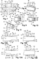
- the pivoting connection device comprises an immobilization system 88 of the cylindrical axis 64 and of the guide ring 76 relative to one another, configured to occupy a free state, visible on the figure 12A , in which the cylindrical axis 64 and the guide ring 76 slide relative to each other in a direction parallel to the pivot axis A64, and a locked state, visible on the figure 12B in which the cylindrical axis 64 and the guide ring 76 are immobilized relative to each other in the longitudinal direction, in both directions.
- the immobilizer 88 includes shapes at the cylindrical axis 64 and the extension 84 of the guide ring 76 which are configured to cooperate with each other when the immobilizer system is in the off state.
- the immobilization system 88 comprises at least one groove 90 which extends over the entire circumference of the peripheral face 72 of the cylindrical axis 64, in a transverse plane.
- the immobilization system 88 comprises at least one rib 92, at the inner face 85 of the extension 84 of the guide ring 76, the shapes of which are complementary to those of the groove 90 of the cylindrical axis 64 .
- the groove 90 and the rib 92 have identical trapezoidal sections and each have two flared lateral walls 94 (referenced on FIG. figure 12A ) which promote the introduction or the exit of the rib 92 of the groove 90.
- the extension 84 is configured to be able to deform radially elastically, thanks in particular to the slots 86, to allow the rib 92 to slide on the cylindrical axis 64 (as shown in FIG. figure 12A ) when it is not positioned at the right of the groove 90 and penetrating into said groove 90 (as shown in FIG. figure 12B ) when the rib 92 and the groove 90 are positioned to the right of each other.
- the pivoting connecting device 50 comprises a locking system 96 configured to occupy a disassembled state (visible on the figure 13A ), in which it allows mounting and sliding of the guide ring 76 in the bore 66 of the first leg 58, and a locked state (visible on the Figure 13B ) in which it is in contact with the outer face FE58 the first leg 58 to lock the guide ring 76 relative to the first leg 58 in the longitudinal direction, in a second direction opposite to the first direction.
- the locking system 96 and the flange 80 immobilize the guide ring 76 relative to the first leg 58 in the longitudinal direction, in both directions.
- the locking system 96 comprises a thread 98, at the portion 82 of the guide ring 76, protruding from the outer face FE58 of the first leg 58 and a locking nut 100 having a tapped bore 102 configured to be screwed onto the thread 98.
- the locknut 100 screwed on the thread 98
- the locking system is in the locked state.
- the flange 80 being in contact with the inner face FI58 of the first leg and the locking nut 100 being in contact with the outer face FE58 of the first leg 58, the guide ring 76 is immobilized in translation with respect to the first branch 58 in the longitudinal direction, in both directions.
- the pivoting connecting device 50 comprises a locking system 104 configured to prevent the immobilization system 88 from moving from the free state to the free state by limiting the radial expansion of the extension. 84 of the guide ring 76.
- the locking system 104 comprises a locking ring 106 configured to slide on the extension 84 and prevent the exit of the rib 92 from the groove 90.
- this locking ring 106 has an internal diameter greater than or equal to the outer diameter of the extension 84 and less than the outer diameter of the extension 84 increased by twice the height (dimension taken in the radial direction) of the rib 92
- the locking ring 106 has an inner diameter substantially equal to the outer diameter of the extension 84 so that there is no radial deformation in the off state.
- the inner surface of the unlocking ring 106 has a slightly frustoconical shape, so as to exert a slight radial pressure on the outer surface of the extension 84 when the unlocking ring 106 is fitted, which corresponds to the blocked state. Because of its flexibility, this pressure generates a slight deformation of the extension 84 in the direction of the cylindrical axis 64 and by consequently a radial pressure between the rib 92 and the groove 90, which generates tangential friction forces preventing the relative rotation of the cylindrical axis 64 relative to the extension 84.
- the locking nut 100 and the locking ring 106 form a single piece.
- the screwing of the locking nut 100 makes it possible to hold the locking ring 106 fitted on the extension 84.
- the pivoting connecting device 50 comprises a rotational system preventing the locking nut 100 from unscrewing.
- FIGS. 9, 10, 12A, 12B, 13A and 13B The assembly of the pivoting connecting device is described with regard to FIGS. 9, 10, 12A, 12B, 13A and 13B .
- the guide ring 76 is introduced into the bore 66 of the first branch 58 from the inner face FI58, as illustrated in FIG. figure 9 .
- the guide ring 76 slides in the bore 66 until the flange 80 comes into contact with the inner face FI58 of the first leg 58, as shown in FIG. figure 10 .
- the cylindrical axis 64 is introduced, via the extension 84, into the guide ring 76.
- the shape of the rib 92 promotes the radial expansion of the extension 84 when the end face 74.1 of the cylindrical axis 64 comes into contact with said rib 92.
- the passage of the cylindrical axis 64 to the right of the rib 92 causes the radial expansion of the extension 84 elastically, as shown in FIG. figure 12A .
- the cylindrical axis 64 is introduced into the guide ring 76 until the rib 92 cooperates with the groove 90. Due to its elasticity, the extension 84 returns to its cylindrical shape, as shown in FIG. figure 12B .
- Immobilizer 88 is in the off state.
- the cylindrical axis 64 and the guide ring 76 are immobilized relative to each other in the longitudinal direction.
- the locking nut 100 and the locking ring 106 are fitted onto the extension 84, as illustrated in FIG. figure 13A .
- the locking nut 100 is screwed onto the threaded section 82 of the guide ring 76 until it comes into contact with the outer face FE58 of the first branch 58.
- the guide ring 76 is then immobilized with respect to the first branch 58 in a longitudinal direction, as illustrated in FIG. Figure 13B .
- the cylindrical axis 64 being immobilized with respect to the guide ring 76 in the direction longitudinal, it finds itself immobilized relative to the first branch 58 in the longitudinal direction.
- the locking ring 106 being connected to the locking nut 100 when the latter is screwed, it is found fitted on the extension 84 and prevents any radial expansion of the latter.
- the pivoting connecting device can be assembled from only one side of the yoke 56.
- the outer face FE60 of the second branch 60 can be inaccessible.
- the pivoting connection device does not induce any radial load in the bore of one of the branches, unlike the second embodiment of the prior art. Finally, none of the other parts of the pivotal connection device is subjected to constraints in the locked state.
Landscapes
- Engineering & Computer Science (AREA)
- General Engineering & Computer Science (AREA)
- Mechanical Engineering (AREA)
- Aviation & Aerospace Engineering (AREA)
- Pivots And Pivotal Connections (AREA)
- Mutual Connection Of Rods And Tubes (AREA)
Applications Claiming Priority (1)
| Application Number | Priority Date | Filing Date | Title |
|---|---|---|---|
| FR1853088A FR3079892B1 (fr) | 2018-04-10 | 2018-04-10 | Dispositif de liaison pivotante entre au moins deux pieces, aeronef comprenant un capot equipe dudit dispositif de liaison pivotante |
Publications (2)
| Publication Number | Publication Date |
|---|---|
| EP3553331A1 true EP3553331A1 (de) | 2019-10-16 |
| EP3553331B1 EP3553331B1 (de) | 2020-08-19 |
Family
ID=62597722
Family Applications (1)
| Application Number | Title | Priority Date | Filing Date |
|---|---|---|---|
| EP19163514.3A Active EP3553331B1 (de) | 2018-04-10 | 2019-03-18 | Verbindungsvorrichtung, die zwischen mindestens zwei teilen schwenkbar ist, luftfahrzeug, das eine abdeckung umfasst, die mit dieser schwenkbaren verbindungsvorrichtung ausgestattet ist |
Country Status (3)
| Country | Link |
|---|---|
| US (1) | US11192659B2 (de) |
| EP (1) | EP3553331B1 (de) |
| FR (1) | FR3079892B1 (de) |
Cited By (3)
| Publication number | Priority date | Publication date | Assignee | Title |
|---|---|---|---|---|
| WO2021205105A1 (fr) | 2020-04-10 | 2021-10-14 | Safran Nacelles | Charniere d'articulation entre deux panneaux d'un ensemble propulsif d'aeronef |
| EP4015850A1 (de) * | 2020-12-21 | 2022-06-22 | Airbus Operations Limited | Stiftverbindungsanordnung |
| EP3896299B1 (de) * | 2020-01-06 | 2025-08-13 | Rohr, Inc. | Scharnieranordnung mit einem ausfallsicheren scharnierstift |
Families Citing this family (8)
| Publication number | Priority date | Publication date | Assignee | Title |
|---|---|---|---|---|
| US10751800B2 (en) | 2017-07-25 | 2020-08-25 | Divergent Technologies, Inc. | Methods and apparatus for additively manufactured exoskeleton-based transport structures |
| US10612491B2 (en) * | 2017-09-25 | 2020-04-07 | Rohr, Inc. | Mounting device with pin actuator |
| US11408216B2 (en) * | 2018-03-20 | 2022-08-09 | Divergent Technologies, Inc. | Systems and methods for co-printed or concurrently assembled hinge structures |
| US11590727B2 (en) | 2018-05-21 | 2023-02-28 | Divergent Technologies, Inc. | Custom additively manufactured core structures |
| US10906661B2 (en) * | 2018-11-05 | 2021-02-02 | Rohr, Inc. | Nacelle cowl hinge |
| EP3751161B1 (de) * | 2019-06-14 | 2023-09-27 | Safran Landing Systems UK Ltd | Selbstschmierende buchsenanordnung |
| FR3104219B1 (fr) * | 2019-12-10 | 2021-12-10 | Airbus Operations Sas | Assemblage comprenant un axe de liaison immobile en translation et en rotation, attache-moteur ou aéronef comprenant un tel assemblage |
| GB2602822A (en) * | 2021-01-15 | 2022-07-20 | Airbus Operations Ltd | A pin joint assembly |
Citations (5)
| Publication number | Priority date | Publication date | Assignee | Title |
|---|---|---|---|---|
| FR2118756A5 (de) * | 1970-12-18 | 1972-07-28 | Meteor Res Ltd | |
| FR2721365A1 (fr) * | 1994-06-15 | 1995-12-22 | Porsche Ag | Liaison articulée de deux éléments de construction adjacents, en particulier d'une capote. |
| US20070289096A1 (en) * | 2006-05-18 | 2007-12-20 | Zhang Mike She Shun | Two bar hinge assembly for casement windows |
| FR2947592A1 (fr) | 2009-07-06 | 2011-01-07 | Airbus Operations Sas | Dispositif de liaison mecanique d'au moins deux pieces a alesages coaxiaux |
| FR3014972A1 (fr) * | 2013-12-12 | 2015-06-19 | Airbus Operations Sas | Assemblage comprenant un axe d'articulation supporte par une chape et immobilise en translation par un dispositif de blocage integrant un double systeme d'anti-rotation |
-
2018
- 2018-04-10 FR FR1853088A patent/FR3079892B1/fr not_active Expired - Fee Related
-
2019
- 2019-03-18 EP EP19163514.3A patent/EP3553331B1/de active Active
- 2019-03-28 US US16/367,585 patent/US11192659B2/en active Active
Patent Citations (5)
| Publication number | Priority date | Publication date | Assignee | Title |
|---|---|---|---|---|
| FR2118756A5 (de) * | 1970-12-18 | 1972-07-28 | Meteor Res Ltd | |
| FR2721365A1 (fr) * | 1994-06-15 | 1995-12-22 | Porsche Ag | Liaison articulée de deux éléments de construction adjacents, en particulier d'une capote. |
| US20070289096A1 (en) * | 2006-05-18 | 2007-12-20 | Zhang Mike She Shun | Two bar hinge assembly for casement windows |
| FR2947592A1 (fr) | 2009-07-06 | 2011-01-07 | Airbus Operations Sas | Dispositif de liaison mecanique d'au moins deux pieces a alesages coaxiaux |
| FR3014972A1 (fr) * | 2013-12-12 | 2015-06-19 | Airbus Operations Sas | Assemblage comprenant un axe d'articulation supporte par une chape et immobilise en translation par un dispositif de blocage integrant un double systeme d'anti-rotation |
Cited By (6)
| Publication number | Priority date | Publication date | Assignee | Title |
|---|---|---|---|---|
| EP3896299B1 (de) * | 2020-01-06 | 2025-08-13 | Rohr, Inc. | Scharnieranordnung mit einem ausfallsicheren scharnierstift |
| WO2021205105A1 (fr) | 2020-04-10 | 2021-10-14 | Safran Nacelles | Charniere d'articulation entre deux panneaux d'un ensemble propulsif d'aeronef |
| FR3109141A1 (fr) * | 2020-04-10 | 2021-10-15 | Safran Nacelles | Charnière d’articulation entre deux panneaux d’un ensemble propulsif d’aéronef |
| US12173750B2 (en) | 2020-04-10 | 2024-12-24 | Safran Nacelles | Hinge for articulating two panels of an aircraft propulsion assembly |
| EP4015850A1 (de) * | 2020-12-21 | 2022-06-22 | Airbus Operations Limited | Stiftverbindungsanordnung |
| US12043381B2 (en) | 2020-12-21 | 2024-07-23 | Airbus Operations Limited | Pin joint assembly |
Also Published As
| Publication number | Publication date |
|---|---|
| EP3553331B1 (de) | 2020-08-19 |
| US11192659B2 (en) | 2021-12-07 |
| FR3079892B1 (fr) | 2020-03-27 |
| US20190308739A1 (en) | 2019-10-10 |
| FR3079892A1 (fr) | 2019-10-11 |
Similar Documents
| Publication | Publication Date | Title |
|---|---|---|
| EP3553331B1 (de) | Verbindungsvorrichtung, die zwischen mindestens zwei teilen schwenkbar ist, luftfahrzeug, das eine abdeckung umfasst, die mit dieser schwenkbaren verbindungsvorrichtung ausgestattet ist | |
| FR3014973A1 (fr) | Assemblage comprenant un axe d'articulation supporte par une chape et immobilise en translation par un dispositif de blocage integrant un double systeme d'anti-rotation | |
| EP0327440A1 (de) | Verbindung zwischen einem Wärmeaustauscher und einem Rohrende | |
| FR2669709A1 (fr) | Dispositif de raccord, notamment pour l'assemblage d'une durite a un echangeur de chaleur de vehicule automobile. | |
| FR3014972A1 (fr) | Assemblage comprenant un axe d'articulation supporte par une chape et immobilise en translation par un dispositif de blocage integrant un double systeme d'anti-rotation | |
| FR3014971A1 (fr) | Assemblage comprenant un axe d'articulation supporte par une chape et immobilise en translation par un dispositif de blocage integrant un double systeme d'anti-rotation | |
| FR3002574A1 (fr) | Butee a hauteur auto-reglable pour un ouvrant de vehicule automobile et procede pour regler une telle butee | |
| WO1998043010A1 (fr) | Collier de serrage pour le raccordement de deux tubes | |
| FR2810087A1 (fr) | Element pourvu exterieurement de moyens pour cooperer avec un taraudage | |
| EP0536005B1 (de) | Vorrichtung zum schnellen Montieren und Demontieren von zwei aufeinanderliegenden Teilen | |
| EP2571113B1 (de) | Befestigungs- und Schnellverbindungsvorrichtung für zweiteiligen Anschluss | |
| FR3080666A1 (fr) | Systeme de serrage a pattes rabattables pour le raccordement de tubes | |
| EP1813826B1 (de) | Vorrichtung für eine lösbare Verbindung, die eine Verriegelungsklammer umfasst | |
| EP3683150B1 (de) | Verbindungsvorrichtung, die zwischen mindestens zwei teilen schwenkbar ist, luftfahrzeug, das eine abdeckung umfasst, die mit dieser schwenkbaren verbindungsvorrichtung ausgestattet ist | |
| WO2021160941A1 (fr) | Bielle ajustable en longueur munie d'un dispositif de couple résistant | |
| EP2446155B1 (de) | Plastikmutter-befestigungvorrichtung | |
| FR3081442A1 (fr) | Dispositif de liaison pivotante entre au moins deux pieces, aeronef comprenant un capot equipe dudit dispositif de liaison pivotante | |
| EP1605195B1 (de) | Rohrkupplungssystem und dazu gehöriges Montageverfahren | |
| FR2799515A1 (fr) | Systeme a rattrapage de jeu pour fixer deux pieces l'une a l'autre au moyen d'un organe de fixation du type a vis | |
| EP3859174B1 (de) | Mutter, die eine schwenkbare unterlegscheibe mit einer exzentrischen durchgangsöffnung umfasst, diese mutter umfassender bolzen und baugruppe, die mindestens einen solchen bolzen umfasst | |
| FR2607201A1 (fr) | Dispositif de fixation sur fut filete ou annele | |
| FR2763657A1 (fr) | Dispositif de fixation d'un element a un support mince | |
| FR3094047A3 (fr) | Liaison entre deux éléments montés articulés l’un à l’autre. | |
| FR3084704A1 (fr) | Dispositif de liaison pivotante entre au moins deux pieces, aeronef comprenant un capot equipe dudit dispositif de liaison pivotante | |
| FR2658878A1 (fr) | Dispositif de connexion rapide entre deux portions d'une timonerie, notamment pour vehicule automobile. |
Legal Events
| Date | Code | Title | Description |
|---|---|---|---|
| PUAI | Public reference made under article 153(3) epc to a published international application that has entered the european phase |
Free format text: ORIGINAL CODE: 0009012 |
|
| STAA | Information on the status of an ep patent application or granted ep patent |
Free format text: STATUS: REQUEST FOR EXAMINATION WAS MADE |
|
| STAA | Information on the status of an ep patent application or granted ep patent |
Free format text: STATUS: EXAMINATION IS IN PROGRESS |
|
| 17P | Request for examination filed |
Effective date: 20190318 |
|
| AK | Designated contracting states |
Kind code of ref document: A1 Designated state(s): AL AT BE BG CH CY CZ DE DK EE ES FI FR GB GR HR HU IE IS IT LI LT LU LV MC MK MT NL NO PL PT RO RS SE SI SK SM TR |
|
| AX | Request for extension of the european patent |
Extension state: BA ME |
|
| 17Q | First examination report despatched |
Effective date: 20191001 |
|
| GRAP | Despatch of communication of intention to grant a patent |
Free format text: ORIGINAL CODE: EPIDOSNIGR1 |
|
| STAA | Information on the status of an ep patent application or granted ep patent |
Free format text: STATUS: GRANT OF PATENT IS INTENDED |
|
| INTG | Intention to grant announced |
Effective date: 20200326 |
|
| RBV | Designated contracting states (corrected) |
Designated state(s): AL AT BE BG CH CY CZ DE DK EE ES FI FR GB GR HR HU IE IS IT LI LT LU LV MC MK MT NL NO PL PT RO RS SE SI SK SM TR |
|
| GRAJ | Information related to disapproval of communication of intention to grant by the applicant or resumption of examination proceedings by the epo deleted |
Free format text: ORIGINAL CODE: EPIDOSDIGR1 |
|
| STAA | Information on the status of an ep patent application or granted ep patent |
Free format text: STATUS: EXAMINATION IS IN PROGRESS |
|
| GRAR | Information related to intention to grant a patent recorded |
Free format text: ORIGINAL CODE: EPIDOSNIGR71 |
|
| GRAS | Grant fee paid |
Free format text: ORIGINAL CODE: EPIDOSNIGR3 |
|
| STAA | Information on the status of an ep patent application or granted ep patent |
Free format text: STATUS: GRANT OF PATENT IS INTENDED |
|
| GRAA | (expected) grant |
Free format text: ORIGINAL CODE: 0009210 |
|
| STAA | Information on the status of an ep patent application or granted ep patent |
Free format text: STATUS: THE PATENT HAS BEEN GRANTED |
|
| INTC | Intention to grant announced (deleted) | ||
| RIC1 | Information provided on ipc code assigned before grant |
Ipc: B64D 29/08 20060101ALI20200619BHEP Ipc: E05D 5/12 20060101ALI20200619BHEP Ipc: B64D 29/06 20060101ALI20200619BHEP Ipc: F16C 11/04 20060101AFI20200619BHEP |
|
| INTG | Intention to grant announced |
Effective date: 20200708 |
|
| AK | Designated contracting states |
Kind code of ref document: B1 Designated state(s): AL AT BE BG CH CY CZ DE DK EE ES FI FR GB GR HR HU IE IS IT LI LT LU LV MC MK MT NL NO PL PT RO RS SE SI SK SM TR |
|
| REG | Reference to a national code |
Ref country code: CH Ref legal event code: EP |
|
| REG | Reference to a national code |
Ref country code: DE Ref legal event code: R096 Ref document number: 602019000493 Country of ref document: DE |
|
| REG | Reference to a national code |
Ref country code: AT Ref legal event code: REF Ref document number: 1304255 Country of ref document: AT Kind code of ref document: T Effective date: 20200915 |
|
| REG | Reference to a national code |
Ref country code: IE Ref legal event code: FG4D Free format text: LANGUAGE OF EP DOCUMENT: FRENCH |
|
| REG | Reference to a national code |
Ref country code: LT Ref legal event code: MG4D |
|
| REG | Reference to a national code |
Ref country code: NL Ref legal event code: MP Effective date: 20200819 |
|
| PG25 | Lapsed in a contracting state [announced via postgrant information from national office to epo] |
Ref country code: GR Free format text: LAPSE BECAUSE OF FAILURE TO SUBMIT A TRANSLATION OF THE DESCRIPTION OR TO PAY THE FEE WITHIN THE PRESCRIBED TIME-LIMIT Effective date: 20201120 Ref country code: HR Free format text: LAPSE BECAUSE OF FAILURE TO SUBMIT A TRANSLATION OF THE DESCRIPTION OR TO PAY THE FEE WITHIN THE PRESCRIBED TIME-LIMIT Effective date: 20200819 Ref country code: LT Free format text: LAPSE BECAUSE OF FAILURE TO SUBMIT A TRANSLATION OF THE DESCRIPTION OR TO PAY THE FEE WITHIN THE PRESCRIBED TIME-LIMIT Effective date: 20200819 Ref country code: SE Free format text: LAPSE BECAUSE OF FAILURE TO SUBMIT A TRANSLATION OF THE DESCRIPTION OR TO PAY THE FEE WITHIN THE PRESCRIBED TIME-LIMIT Effective date: 20200819 Ref country code: BG Free format text: LAPSE BECAUSE OF FAILURE TO SUBMIT A TRANSLATION OF THE DESCRIPTION OR TO PAY THE FEE WITHIN THE PRESCRIBED TIME-LIMIT Effective date: 20201119 Ref country code: FI Free format text: LAPSE BECAUSE OF FAILURE TO SUBMIT A TRANSLATION OF THE DESCRIPTION OR TO PAY THE FEE WITHIN THE PRESCRIBED TIME-LIMIT Effective date: 20200819 Ref country code: NO Free format text: LAPSE BECAUSE OF FAILURE TO SUBMIT A TRANSLATION OF THE DESCRIPTION OR TO PAY THE FEE WITHIN THE PRESCRIBED TIME-LIMIT Effective date: 20201119 Ref country code: PT Free format text: LAPSE BECAUSE OF FAILURE TO SUBMIT A TRANSLATION OF THE DESCRIPTION OR TO PAY THE FEE WITHIN THE PRESCRIBED TIME-LIMIT Effective date: 20201221 |
|
| REG | Reference to a national code |
Ref country code: AT Ref legal event code: MK05 Ref document number: 1304255 Country of ref document: AT Kind code of ref document: T Effective date: 20200819 |
|
| PG25 | Lapsed in a contracting state [announced via postgrant information from national office to epo] |
Ref country code: RS Free format text: LAPSE BECAUSE OF FAILURE TO SUBMIT A TRANSLATION OF THE DESCRIPTION OR TO PAY THE FEE WITHIN THE PRESCRIBED TIME-LIMIT Effective date: 20200819 Ref country code: PL Free format text: LAPSE BECAUSE OF FAILURE TO SUBMIT A TRANSLATION OF THE DESCRIPTION OR TO PAY THE FEE WITHIN THE PRESCRIBED TIME-LIMIT Effective date: 20200819 Ref country code: NL Free format text: LAPSE BECAUSE OF FAILURE TO SUBMIT A TRANSLATION OF THE DESCRIPTION OR TO PAY THE FEE WITHIN THE PRESCRIBED TIME-LIMIT Effective date: 20200819 Ref country code: LV Free format text: LAPSE BECAUSE OF FAILURE TO SUBMIT A TRANSLATION OF THE DESCRIPTION OR TO PAY THE FEE WITHIN THE PRESCRIBED TIME-LIMIT Effective date: 20200819 Ref country code: IS Free format text: LAPSE BECAUSE OF FAILURE TO SUBMIT A TRANSLATION OF THE DESCRIPTION OR TO PAY THE FEE WITHIN THE PRESCRIBED TIME-LIMIT Effective date: 20201219 |
|
| PG25 | Lapsed in a contracting state [announced via postgrant information from national office to epo] |
Ref country code: SM Free format text: LAPSE BECAUSE OF FAILURE TO SUBMIT A TRANSLATION OF THE DESCRIPTION OR TO PAY THE FEE WITHIN THE PRESCRIBED TIME-LIMIT Effective date: 20200819 Ref country code: RO Free format text: LAPSE BECAUSE OF FAILURE TO SUBMIT A TRANSLATION OF THE DESCRIPTION OR TO PAY THE FEE WITHIN THE PRESCRIBED TIME-LIMIT Effective date: 20200819 Ref country code: CZ Free format text: LAPSE BECAUSE OF FAILURE TO SUBMIT A TRANSLATION OF THE DESCRIPTION OR TO PAY THE FEE WITHIN THE PRESCRIBED TIME-LIMIT Effective date: 20200819 Ref country code: DK Free format text: LAPSE BECAUSE OF FAILURE TO SUBMIT A TRANSLATION OF THE DESCRIPTION OR TO PAY THE FEE WITHIN THE PRESCRIBED TIME-LIMIT Effective date: 20200819 Ref country code: EE Free format text: LAPSE BECAUSE OF FAILURE TO SUBMIT A TRANSLATION OF THE DESCRIPTION OR TO PAY THE FEE WITHIN THE PRESCRIBED TIME-LIMIT Effective date: 20200819 |
|
| REG | Reference to a national code |
Ref country code: DE Ref legal event code: R097 Ref document number: 602019000493 Country of ref document: DE |
|
| PG25 | Lapsed in a contracting state [announced via postgrant information from national office to epo] |
Ref country code: AL Free format text: LAPSE BECAUSE OF FAILURE TO SUBMIT A TRANSLATION OF THE DESCRIPTION OR TO PAY THE FEE WITHIN THE PRESCRIBED TIME-LIMIT Effective date: 20200819 Ref country code: AT Free format text: LAPSE BECAUSE OF FAILURE TO SUBMIT A TRANSLATION OF THE DESCRIPTION OR TO PAY THE FEE WITHIN THE PRESCRIBED TIME-LIMIT Effective date: 20200819 Ref country code: ES Free format text: LAPSE BECAUSE OF FAILURE TO SUBMIT A TRANSLATION OF THE DESCRIPTION OR TO PAY THE FEE WITHIN THE PRESCRIBED TIME-LIMIT Effective date: 20200819 |
|
| PLBE | No opposition filed within time limit |
Free format text: ORIGINAL CODE: 0009261 |
|
| STAA | Information on the status of an ep patent application or granted ep patent |
Free format text: STATUS: NO OPPOSITION FILED WITHIN TIME LIMIT |
|
| PG25 | Lapsed in a contracting state [announced via postgrant information from national office to epo] |
Ref country code: SK Free format text: LAPSE BECAUSE OF FAILURE TO SUBMIT A TRANSLATION OF THE DESCRIPTION OR TO PAY THE FEE WITHIN THE PRESCRIBED TIME-LIMIT Effective date: 20200819 |
|
| 26N | No opposition filed |
Effective date: 20210520 |
|
| PG25 | Lapsed in a contracting state [announced via postgrant information from national office to epo] |
Ref country code: IT Free format text: LAPSE BECAUSE OF FAILURE TO SUBMIT A TRANSLATION OF THE DESCRIPTION OR TO PAY THE FEE WITHIN THE PRESCRIBED TIME-LIMIT Effective date: 20200819 |
|
| PG25 | Lapsed in a contracting state [announced via postgrant information from national office to epo] |
Ref country code: SI Free format text: LAPSE BECAUSE OF FAILURE TO SUBMIT A TRANSLATION OF THE DESCRIPTION OR TO PAY THE FEE WITHIN THE PRESCRIBED TIME-LIMIT Effective date: 20200819 |
|
| PG25 | Lapsed in a contracting state [announced via postgrant information from national office to epo] |
Ref country code: MC Free format text: LAPSE BECAUSE OF FAILURE TO SUBMIT A TRANSLATION OF THE DESCRIPTION OR TO PAY THE FEE WITHIN THE PRESCRIBED TIME-LIMIT Effective date: 20200819 |
|
| REG | Reference to a national code |
Ref country code: BE Ref legal event code: MM Effective date: 20210331 |
|
| PG25 | Lapsed in a contracting state [announced via postgrant information from national office to epo] |
Ref country code: IE Free format text: LAPSE BECAUSE OF NON-PAYMENT OF DUE FEES Effective date: 20210318 Ref country code: LU Free format text: LAPSE BECAUSE OF NON-PAYMENT OF DUE FEES Effective date: 20210318 |
|
| PG25 | Lapsed in a contracting state [announced via postgrant information from national office to epo] |
Ref country code: BE Free format text: LAPSE BECAUSE OF NON-PAYMENT OF DUE FEES Effective date: 20210331 |
|
| REG | Reference to a national code |
Ref country code: CH Ref legal event code: PL |
|
| PG25 | Lapsed in a contracting state [announced via postgrant information from national office to epo] |
Ref country code: LI Free format text: LAPSE BECAUSE OF NON-PAYMENT OF DUE FEES Effective date: 20220331 Ref country code: CH Free format text: LAPSE BECAUSE OF NON-PAYMENT OF DUE FEES Effective date: 20220331 |
|
| PG25 | Lapsed in a contracting state [announced via postgrant information from national office to epo] |
Ref country code: CY Free format text: LAPSE BECAUSE OF FAILURE TO SUBMIT A TRANSLATION OF THE DESCRIPTION OR TO PAY THE FEE WITHIN THE PRESCRIBED TIME-LIMIT Effective date: 20200819 |
|
| PG25 | Lapsed in a contracting state [announced via postgrant information from national office to epo] |
Ref country code: HU Free format text: LAPSE BECAUSE OF FAILURE TO SUBMIT A TRANSLATION OF THE DESCRIPTION OR TO PAY THE FEE WITHIN THE PRESCRIBED TIME-LIMIT; INVALID AB INITIO Effective date: 20190318 |
|
| GBPC | Gb: european patent ceased through non-payment of renewal fee |
Effective date: 20230318 |
|
| PG25 | Lapsed in a contracting state [announced via postgrant information from national office to epo] |
Ref country code: GB Free format text: LAPSE BECAUSE OF NON-PAYMENT OF DUE FEES Effective date: 20230318 |
|
| PG25 | Lapsed in a contracting state [announced via postgrant information from national office to epo] |
Ref country code: GB Free format text: LAPSE BECAUSE OF NON-PAYMENT OF DUE FEES Effective date: 20230318 |
|
| PG25 | Lapsed in a contracting state [announced via postgrant information from national office to epo] |
Ref country code: MK Free format text: LAPSE BECAUSE OF FAILURE TO SUBMIT A TRANSLATION OF THE DESCRIPTION OR TO PAY THE FEE WITHIN THE PRESCRIBED TIME-LIMIT Effective date: 20200819 |
|
| PG25 | Lapsed in a contracting state [announced via postgrant information from national office to epo] |
Ref country code: MT Free format text: LAPSE BECAUSE OF FAILURE TO SUBMIT A TRANSLATION OF THE DESCRIPTION OR TO PAY THE FEE WITHIN THE PRESCRIBED TIME-LIMIT Effective date: 20200819 |
|
| PG25 | Lapsed in a contracting state [announced via postgrant information from national office to epo] |
Ref country code: TR Free format text: LAPSE BECAUSE OF FAILURE TO SUBMIT A TRANSLATION OF THE DESCRIPTION OR TO PAY THE FEE WITHIN THE PRESCRIBED TIME-LIMIT Effective date: 20200819 |
|
| PGFP | Annual fee paid to national office [announced via postgrant information from national office to epo] |
Ref country code: DE Payment date: 20260319 Year of fee payment: 8 |
|
| PGFP | Annual fee paid to national office [announced via postgrant information from national office to epo] |
Ref country code: FR Payment date: 20260320 Year of fee payment: 8 |