EP3553327B1 - Rod assembly and fluid pressure device - Google Patents
Rod assembly and fluid pressure device Download PDFInfo
- Publication number
- EP3553327B1 EP3553327B1 EP17878720.6A EP17878720A EP3553327B1 EP 3553327 B1 EP3553327 B1 EP 3553327B1 EP 17878720 A EP17878720 A EP 17878720A EP 3553327 B1 EP3553327 B1 EP 3553327B1
- Authority
- EP
- European Patent Office
- Prior art keywords
- rod
- packing
- rod assembly
- magnet
- fluid pressure
- Prior art date
- Legal status (The legal status is an assumption and is not a legal conclusion. Google has not performed a legal analysis and makes no representation as to the accuracy of the status listed.)
- Active
Links
Images


Classifications
-
- F—MECHANICAL ENGINEERING; LIGHTING; HEATING; WEAPONS; BLASTING
- F15—FLUID-PRESSURE ACTUATORS; HYDRAULICS OR PNEUMATICS IN GENERAL
- F15B—SYSTEMS ACTING BY MEANS OF FLUIDS IN GENERAL; FLUID-PRESSURE ACTUATORS, e.g. SERVOMOTORS; DETAILS OF FLUID-PRESSURE SYSTEMS, NOT OTHERWISE PROVIDED FOR
- F15B15/00—Fluid-actuated devices for displacing a member from one position to another; Gearing associated therewith
- F15B15/08—Characterised by the construction of the motor unit
- F15B15/14—Characterised by the construction of the motor unit of the straight-cylinder type
- F15B15/1423—Component parts; Constructional details
- F15B15/1447—Pistons; Piston to piston rod assemblies
-
- F—MECHANICAL ENGINEERING; LIGHTING; HEATING; WEAPONS; BLASTING
- F15—FLUID-PRESSURE ACTUATORS; HYDRAULICS OR PNEUMATICS IN GENERAL
- F15B—SYSTEMS ACTING BY MEANS OF FLUIDS IN GENERAL; FLUID-PRESSURE ACTUATORS, e.g. SERVOMOTORS; DETAILS OF FLUID-PRESSURE SYSTEMS, NOT OTHERWISE PROVIDED FOR
- F15B15/00—Fluid-actuated devices for displacing a member from one position to another; Gearing associated therewith
- F15B15/20—Other details, e.g. assembly with regulating devices
- F15B15/22—Other details, e.g. assembly with regulating devices for accelerating or decelerating the stroke
- F15B15/226—Other details, e.g. assembly with regulating devices for accelerating or decelerating the stroke having elastic elements, e.g. springs, rubber pads
-
- F—MECHANICAL ENGINEERING; LIGHTING; HEATING; WEAPONS; BLASTING
- F15—FLUID-PRESSURE ACTUATORS; HYDRAULICS OR PNEUMATICS IN GENERAL
- F15B—SYSTEMS ACTING BY MEANS OF FLUIDS IN GENERAL; FLUID-PRESSURE ACTUATORS, e.g. SERVOMOTORS; DETAILS OF FLUID-PRESSURE SYSTEMS, NOT OTHERWISE PROVIDED FOR
- F15B15/00—Fluid-actuated devices for displacing a member from one position to another; Gearing associated therewith
- F15B15/20—Other details, e.g. assembly with regulating devices
- F15B15/22—Other details, e.g. assembly with regulating devices for accelerating or decelerating the stroke
- F15B15/228—Other details, e.g. assembly with regulating devices for accelerating or decelerating the stroke having shock absorbers mounted outside the actuator housing
-
- F—MECHANICAL ENGINEERING; LIGHTING; HEATING; WEAPONS; BLASTING
- F16—ENGINEERING ELEMENTS AND UNITS; GENERAL MEASURES FOR PRODUCING AND MAINTAINING EFFECTIVE FUNCTIONING OF MACHINES OR INSTALLATIONS; THERMAL INSULATION IN GENERAL
- F16F—SPRINGS; SHOCK-ABSORBERS; MEANS FOR DAMPING VIBRATION
- F16F7/00—Vibration-dampers; Shock-absorbers
-
- F—MECHANICAL ENGINEERING; LIGHTING; HEATING; WEAPONS; BLASTING
- F16—ENGINEERING ELEMENTS AND UNITS; GENERAL MEASURES FOR PRODUCING AND MAINTAINING EFFECTIVE FUNCTIONING OF MACHINES OR INSTALLATIONS; THERMAL INSULATION IN GENERAL
- F16J—PISTONS; CYLINDERS; SEALINGS
- F16J15/00—Sealings
- F16J15/16—Sealings between relatively-moving surfaces
- F16J15/32—Sealings between relatively-moving surfaces with elastic sealings, e.g. O-rings
- F16J15/3268—Mounting of sealing rings
-
- F—MECHANICAL ENGINEERING; LIGHTING; HEATING; WEAPONS; BLASTING
- F15—FLUID-PRESSURE ACTUATORS; HYDRAULICS OR PNEUMATICS IN GENERAL
- F15B—SYSTEMS ACTING BY MEANS OF FLUIDS IN GENERAL; FLUID-PRESSURE ACTUATORS, e.g. SERVOMOTORS; DETAILS OF FLUID-PRESSURE SYSTEMS, NOT OTHERWISE PROVIDED FOR
- F15B15/00—Fluid-actuated devices for displacing a member from one position to another; Gearing associated therewith
- F15B15/20—Other details, e.g. assembly with regulating devices
- F15B15/28—Means for indicating the position, e.g. end of stroke
- F15B15/2815—Position sensing, i.e. means for continuous measurement of position, e.g. LVDT
- F15B15/2861—Position sensing, i.e. means for continuous measurement of position, e.g. LVDT using magnetic means
Definitions
- the present invention relates to a rod assembly reciprocating along a slide hole and a fluid pressure device.
- fluid pressure devices including pistons configured to be displaced by the effect of supplied pressurized fluid are well known as means (actuators) for transporting workpieces and the like.
- a typical fluid pressure cylinder includes a cylinder tube, a piston disposed inside the cylinder tube to be movable in the axial direction, and a piston rod connected to the piston (for example, see JP 2014-114874 A below).
- pressurized fluid such as air is supplied into the cylinder tube
- the piston is pushed by the pressurized fluid and displaced in the axial direction. This also causes the piston rod connected to the piston to be displaced in the axial direction.
- JP H11 132 204 A describes a cylinder device having a piston sliding in the inner circumferential face of a cylinder tube.
- the piston is composed of at least three members of an intermediate piston member, a first piston member and a second piston member that are arranged on both sides of the intermediate piston member.
- the intermediate piston member comprises a holding member which is formed from a nonmagnetic material and comprises holes formed in the axial direction. Permanent magnets are provided in the respective holes. Sealing elements in the form of O-rings are provided on the circumference of the piston for contacting the inner circumferential part of the slide hole.
- CN 104 895 862 A describes a hydraulic oil cylinder with a displacement sensor.
- the hydraulic oil cylinder comprises a hollow piston rod with an inner end sealed.
- External threads are arranged at the outer end of the piston rod forming a threaded connection with an adapting seat.
- a sensor hole is formed on the outer end of the piston rod and a magneto strictive linear displacement sensor is arranged in that sensor hole.
- DE 94 16 082 U1 describes a piston cylinder arrangement, wherein one end of the cylinder comprises a cylinder cover.
- a piston is provided in the cylinder, wherein a small gap is provided between the outer circumference of the piston and the inner circumference of the cylinder bore in order to reduce friction.
- US 2006 0162 551 A1 describes a piston for a fluid operated power cylinder having two mutually coaxial sealing lips axially extending away from each other and being able to radially yield for sealing engagement with the piston running face of the power cylinder and adjacent to at least one piston end side an elastic buffer body serving for shock absorbing in the end of the stroke position of the piston.
- US 2015 0354 608 A1 describes a drive unit of a fluid actuated linear drive including a piston rod, an annular drive piston seated coaxially on the piston rod and a buffer sleeve which is likewise seated coaxially on the piston rod. These elements are fixed by the same common weld joint.
- US 2015 0226 325 A1 describes a piston unit of a working cylinder having a first and second coupling partner.
- the first coupling partner is a piston
- the second coupling partner is a piston rod.
- the piston rod is inserted axially into the piston.
- Both coupling partners comprise a groove laying opposite to each other, such that a spring-loaded coupling ring is able to secure both coupling partners with respect to each other.
- GB 1 103 118 A describes a fluid actuated cylinder and piston mechanism.
- the Piston is housed in the cylinder.
- the piston comprises a ring permanent magnet clamped be-tween two end plates mounted to the inner end of a non-magnetic piston rod.
- EP 0 093 859 A2 describes a piston for sensing the piston position in a non-touching manner.
- the piston comprises an annular magnet provided on a sleeve. The magnet abuts two profile discs. The magnet, profile discs and piston are covered by a sealing material 18.
- a piston and a piston rod in a conventional fluid pressure device are assembled together by, for example, inserting one end portion of the piston rod into a hole formed in the central part of the piston and swaging or crimping (plastically deforming) the one end portion.
- the assembly requires specific tools or devices and thus is complicated.
- the present invention has been devised taking into consideration the aforementioned problems, and has the object of providing a rod assembly and a fluid pressure device capable of being assembled through a simplified process.
- the rod member includes, in the outer circumferential part, a stopper receiving groove extending in a circumferential direction.
- a stopper member divided into a plurality of elements in the circumferential direction is installed into the stopper receiving groove.
- the packing covers the stopper member, and thus the stopper member supports the packing and is prevented from coming off the stopper receiving groove.
- the packing may also function as a damper configured to relieve impact occurring when the rod member reaches a stroke end.
- the rod member may have a hollow shape.
- a damper member configured to relieve impact occurring when the rod member reaches a stroke end may be attached to an end portion of the rod member, and the damper member may airtightly or liquid-tightly block up a hollow portion of the rod member.
- An outer circumferential part of the damper member may be attached to an inner circumferential part of the rod member.
- a supporting member configured to be harder than the damper member and to support the damper member may be disposed in the hollow portion of the rod member.
- the rod member may include a magnet receiving groove in an outer circumferential part thereof, and a magnet having an annular shape may be installed in the magnet receiving groove.
- the packing may be provided with at least one magnet receiving groove having a depth in an axial direction, and a magnet may be installed in the at least one magnet receiving groove.
- An outer circumference of the packing may have a non-circular shape
- the at least one magnet receiving groove may include a plurality of magnet receiving grooves disposed at intervals in a circumferential direction, and the magnet may be installed in only part of the plurality of magnet receiving grooves.
- a fluid pressure device includes a body containing therein a slide hole and a rod assembly disposed so as to reciprocate along the slide hole, wherein the rod assembly includes a rod member and a packing attached to an outer circumferential part of the rod member and configured to slide along the slide hole.
- the fluid pressure device may be configured as a fluid pressure cylinder, a valve device, a length-measurement cylinder, a sliding table, or a chuck device.
- the packing is attached to the outer circumferential part of the rod member.
- a hitherto-used hard piston member can be omitted, enabling easy assembly of the rod assembly.
- the assembly can be easily performed by hand without using any specific tools. Consequently, according to the present invention, the assembly work of the rod assembly can be simplified.
- consumption of pressurized fluid (air or the like) when the rod member moves toward at least one side during the reciprocating motion inside the slide hole can be reduced by increasing the outer diameter of the rod member.
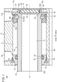
- a fluid pressure cylinder 10A illustrated in FIG. 1 as an example of a fluid pressure device is provided with a cylinder tube 12 (body) having a hollow tubular shape, a head cover 14 disposed at one end portion of the cylinder tube 12, a rod cover 16 disposed at another end portion of the cylinder tube 12, and a rod assembly 17A disposed to be able to reciprocate in the axial direction of the cylinder tube 12.
- the fluid pressure cylinder 10A is used as an actuator for, for example, transporting a workpiece.
- the cylinder tube 12 is a tubular body composed of, for example, a metal material such as aluminum alloy and extending in the axial direction.
- the cylinder tube 12 has a hollow cylindrical shape.
- the cylinder tube 12 has a first port 12a disposed adjacent to one end in the axial direction (i.e., an end located in the direction of an arrow X2), a second port 12b disposed adjacent to another end in the axial direction (i.e., an end located in the direction of an arrow X1), and a slide hole 13 (cylinder chamber) communicating with the first port 12a and the second port 12b.
- the head cover 14 is a plate-shaped body composed of, for example, a metal material similar to that of the cylinder tube 12 and is disposed to block up the one end portion (the end portion located in the X2 direction) of the cylinder tube 12.
- the head cover 14 hermetically closes the one end portion of the cylinder tube 12.
- the rod cover 16 is a circular ring-shaped member composed of, for example, a metal material similar to that of the cylinder tube 12 and is disposed to block up the other end portion (the end portion located in the X1 direction) of the cylinder tube 12.
- An outer annular groove 24 is formed in an outer circumferential part of the rod cover 16.
- An outer sealing member 26 composed of an elastic material is installed into the outer annular groove 24 to seal a gap between the outer circumferential surface of the rod cover 16 and the inner circumferential surface of the slide hole 13.
- An inner annular groove 28 is formed in an inner circumferential part of the rod cover 16.
- An inner sealing member 30 composed of an elastic material is installed into the inner annular groove 28 to seal a gap between the inner circumferential surface of the rod cover 16 and the outer circumferential surface of a rod member 20.
- the rod cover 16 is locked by a stopper 32 secured to an inner circumferential part of the cylinder tube 12 adjacent to the other end of the cylinder tube 12.
- the rod assembly 17A includes the rod member 20 extending in the axial direction of the slide hole 13 and a packing 34 attached to an outer circumferential part of the rod member 20.
- the rod member 20 has a hollow shape (a hollow cylindrical shape in the first embodiment) and includes a hollow portion 21 passing through in the axial direction.
- the rod member 20 penetrates through the rod cover 16.
- a distal end portion 20b which is the opposite end of one end portion 20a (hereinafter referred to as "a base end portion 20a") of the rod member 20, is exposed to the outside of the slide hole 13.
- the constituent material of the rod member 20 includes, for example, metal materials such as carbon steel, stainless steel, and aluminum alloy, and hard resin.
- the packing 34 is accommodated inside the cylinder tube 12 (slide hole 13) to be slidable in the axial direction and partitions the inside of the slide hole 13 into a first pressure chamber 13a adjacent to the first port 12a and a second pressure chamber 13b adjacent to the second port 12b.
- the packing 34 is attached to the base end portion 20a of the rod member 20.
- the packing 34 is an annular member protruding radially outward from the rod member 20.
- the outer diameter of the packing 34 is larger than the outer diameter of the rod member 20.
- the rod member 20 is provided with an annular stopper receiving groove 50 and an annular magnet receiving groove 49, which are formed in an outer circumferential part of the rod member in the vicinity of the base end portion 20a so as to be spaced in the axial direction.
- the packing 34 is a circular ring-shaped sealing member (for example, O-ring) composed of an elastic body and attached to the outer circumferential part of the rod member 20, and is disposed to surround the rod member 20.
- the constituent material of the packing 34 includes, for example, elastic materials such as rubber and elastomer (urethane rubber and the like).
- the outer circumferential surface of the packing 34 airtightly or liquid-tightly contacts with the inner circumferential surface of the slide hole 13 over the entire circumference.
- the inner circumferential surface of the packing 34 airtightly or liquid-tightly contacts with the outer circumferential part (outer circumferential surface) of the rod member 20 over the entire circumference.
- the packing 34 airtightly or liquid-tightly separates the first pressure chamber 13a and the second pressure chamber 13b from each other inside the slide hole 13.
- the rod assembly 17A includes the packing 34, which is attached to the outer circumferential part of the rod member 20 so as to airtightly or liquid-tightly separate the first pressure chamber 13a and the second pressure chamber 13b from each other.
- the fluid pressure cylinder has a pistonless structure without a piston member made of a hard material.
- the packing 34 can be regarded as functioning as a piston in the rod assembly 17A.
- the packing 34 also functions as a damper (first damper) relieving impact occurring when the rod member reaches a stroke end on the rod cover 16 side.
- the packing 34 is attached to a stopper member 52 so as to cover the stopper member 52.
- the stopper member 52 has a circular ring shape and is installed into the stopper receiving groove 50 of the rod member 20.
- the packing 34 has an L-shaped cross-section and includes a packing body portion 34a covering a side of the stopper member 52 facing the rod cover 16 (a side located in the direction of the arrow X1) and a circumference covering portion 34b covering the outer circumference of the stopper member 52.
- the circumference covering portion 34b protrudes from an outer circumferential part of the packing body portion 34a in the axial direction.
- the stopper member 52 includes a plurality of circumferentially-segmented stopper elements 52a. Each of the stopper elements 52a is arc-shaped. In the first embodiment, the stopper member 52 is divided into halves and thus consists of the two stopper elements 52a of semicircular arcs. In FIG. 1 , the inner circumference of the stopper member 52 (inner circumferences of the stopper elements 52a) is installed into the stopper receiving groove 50.
- the stopper member 52 is made of a hard material, for example, a material similar to the above-described material of the rod member 20.
- the circumference covering portion 34b is attached to the outer circumference of the stopper member 52.
- the packing 34 is supported by the stopper member 52.
- the stopper member 52 is prevented from coming off the stopper receiving groove 50.
- the circumference covering portion 34b has an annular engaging groove 35 formed in an inner circumferential part thereof.
- the outer circumference of the stopper member 52 engages with the annular engaging groove 35 of the circumference covering portion 34b.
- the circumference covering portion 34b is pushed radially inward by the inner circumferential surface defining the slide hole 13. This prevents the circumference covering portion 34b having the annular engaging groove 35 from coming off the outer circumference of the stopper member 52.
- the rod member 20 and the packing 34 are rotatable relative to each other about an axis a1 of the packing 34.
- the stopper member 52 and the packing 34 are attached to the rod member 20 as follows. First, the two stopper elements 52a are individually attached to (fitted into) the stopper receiving groove 50 of the rod member 20 so as to form the annular stopper member 52. Next, the packing 34 is moved on the rod member 20 from the distal end portion 20b side toward the base end portion 20a side, and then the packing 34 covers the stopper member 52 (two stopper elements 52a). Thus, the stopper member 52 is prevented from coming off the stopper receiving groove 50, and the packing 34 is held at a predetermined position on the outer circumferential part of the rod member 20.
- a magnet 48 is a circular ring-shaped member installed into the outer circumferential part (magnet receiving groove 49) of the rod member 20.
- the magnet 48 is elastically deformable.
- the magnet 48 is a plastic magnet having a slit 54 (gap) at a location in the circumferential direction. Thus, the magnet 48 elastically deforms when being installed into the magnet receiving groove 49, enabling an easy installation.
- the magnet 48 is disposed at a position adjacent to the packing 34. An end surface of the magnet 48 facing the packing 34 is in contact with an end surface of the packing 34 facing the magnet 48. The end surface of the magnet 48 facing the packing 34 may not be in contact with the end surface of the packing 34 facing the magnet 48.
- Magnetic sensors (not illustrated) are attached to the outer surface of the cylinder tube 12 at positions corresponding to both stroke ends of the packing 34 and the magnet 48.
- the magnetic sensors detect magnetism generated by the magnet 48 to thereby detect the working position of the rod assembly 17A.
- a damper member 40 (second damper) relieving impact occurring when the rod member reaches a stroke end on the head cover 14 side is disposed at the base end portion 20a of the rod member 20.
- the damper member 40 is attached to an inner circumferential part of the base end portion 20a of the rod member 20 and protrudes from an end surface 20c of the rod member 20 located at the base end portion 20a toward the head cover 14 (in the direction of the arrow X2).
- the damper member 40 has a circular shape.
- the damper member 40 is provided with an annular (circular ring-shaped) flange portion 40a protruding radially outward.
- the flange portion 40a engages with an annular engaging recess 58 formed in the inner circumferential part of the base end portion 20a of the rod member 20. The engagement between the flange portion 40a and the annular engaging recess 58 prevents the damper member 40 from coming off the base end portion 20a of the rod member 20.
- the rod member 20 has a stepped portion 60 formed on an inner circumferential part of the base end portion 20a.
- a supporting member 62 is disposed on the stepped portion 60.
- the supporting member 62 is a circular plate-shaped member and is held between the stepped portion 60 and the damper member 40.
- the supporting member 62 supports the damper member 40 and prevents the damper member 40 from being bent by pressure from pressurized fluid.
- the supporting member 62 is configured to be harder than the damper member 40.
- the supporting member 62 is made of a hard material, for example, a material similar to the material of the above-described rod member 20.
- an outer circumferential part of the damper member 40 is in close contact with the inner circumferential part of the rod member 20 over the entire circumference and thus airtightly or liquid-tightly closes an opening of the rod member 20 at the base end portion 20a. That is, the damper member 40 also functions as a sealing member for airtightly or liquid-tightly blocking up the hollow portion 21 of the rod member 20.
- the rod assembly 17A is reciprocated in the axial direction by the effect of pressurized fluid (for example, compressed air) introduced via the first port 12a or the second port 12b.
- pressurized fluid for example, compressed air
- the pressurized fluid is supplied from a pressurized fluid supply source (not illustrated) to the first pressure chamber 13a via the first port 12a while the second port 12b is exposed to the atmosphere. This causes the pressurized fluid to push the rod assembly 17A toward the rod cover 16, whereby the rod assembly 17A is advanced.
- the pressurized fluid is supplied from the pressurized fluid supply source (not illustrated) to the second pressure chamber 13b via the second port 12b while the first port 12a is exposed to the atmosphere. This causes the pressurized fluid to push the rod assembly 17A toward the head cover 14, whereby the rod assembly 17A is retracted (returning action).
- the packing 34 is attached to the outer circumferential part of the rod member 20 in the rod assembly 17A according to this embodiment.
- a hitherto-used hard piston member can be omitted, enabling easy assembly of the rod assembly 17A.
- the assembly can be easily performed by hand without using any specific tools. Consequently, the rod assembly 17A of the present invention can simplify the assembly work.
- the rod member 20 has, formed in the outer circumferential part, the stopper receiving groove 50 extending in the circumferential direction, and the stopper member 52, which is circumferentially divided into the plurality of elements, is installed into the stopper receiving groove 50.
- the packing 34 covers the stopper member 52.
- the packing 34 is supported by the stopper member 52, and the stopper member 52 is prevented from coming off the stopper receiving groove 50.
- the packing 34 also functions as a damper for relieving impact occurring when the rod member reaches one of the stroke ends (on the rod cover 16 side in the first embodiment). Thus, impact load is successfully prevented from being transmitted to the rod member 20 when the rod member reaches the one of the stroke ends.
- the rod member 20 has a hollow shape. This leads to a reduction in the weight of the rod assembly 17A. In addition, the reduction in the weight of the rod assembly 17A leads to a reduction in the consumption of the pressurized fluid, resulting in energy savings.
- the rod member 20 and the packing 34 are rotatable relative to each other about the axis a1 of the packing 34. This conveniently allows the rod member 20 to easily rotate during installation of the fluid pressure cylinder 10A in a facility. Moreover, as described below, the rod member 20 is also rotatable in a rod assembly 17B ( FIG. 3 ) provided with a polygonal packing 34A.
- the damper member 40 also functions as a sealing member for airtightly or liquid-tightly blocking up the hollow portion 21 of the rod member 20.
- the number of parts can be reduced compared with a structure including a damper and a sealing member separately.
- the present invention is not limited to the above circular packing 34, and is also applicable to the polygonal packing 34A.
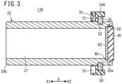
- the fluid pressure cylinder 10A may adopt the rod assembly 17B provided with the polygonal packing 34A shown in FIGS. 3 to 5 .
- the outer circumference of the packing 34A of the rod assembly 17B has an octagonal shape.
- the inner circumference of the packing 34A has a circular shape.
- the packing 34A has a plurality of magnet receiving grooves 70 disposed at intervals in the circumferential direction. Specifically, the plurality of magnet receiving grooves 70 are formed in one surface of the packing 34A and have a depth in the axial direction of the packing 34A.
- a magnet 72 is installed in each of the magnet receiving grooves 70.
- the magnet 72 is, for example, a ferrite magnet, a rare earth magnet, or the like.
- the other part of the rod assembly 17B is configured similarly to the rod assembly 17A.
- the rod assembly 17B yields effects similar to the effects of the rod assembly 17A.
- the rod assembly 17B can also be easily assembled by hand without using any specific tools.
- the above-described rod assembly 17A ( FIG. 1 ) adopts the rod member 20 having a hollow structure.
- rod assemblies 17C to 17E respectively shown in FIGS. 6A to 6C rod members 20A, 20B having a solid structure may be adopted.
- the rod assembly 17C in FIG. 6A adopts the rod member 20A having a solid structure, instead of the rod member 20 in the rod assembly 17A ( FIG. 1 ).
- the packing 34A of the rod assembly 17D in FIG. 6B has a magnet holding portion 74 formed by extending the circumference covering portion 34b of the packing 34 of the rod assembly 17A ( FIG. 1 ) in the axial direction so as to hold a magnet 48A (a magnet having a smaller outer diameter and a larger inner diameter than the magnet 48 of FIG. 1 ) .
- the magnet 48A is held between the magnet holding portion 74 and an outer circumferential part of the rod member 20B.
- a magnet-holding annular groove 74a is formed in the inner circumferential surface of the magnet holding portion 74.
- the outer circumference of the magnet 48A is fitted (engaged) into the magnet-holding annular groove 74a.
- the rod assembly 17D adopts the rod member 20B without a magnet receiving groove in the outer circumferential part.
- the rod member 20A provided with the magnet receiving groove 49 in an outer circumferential part and the packing 34A provided with the magnet holding portion 74 may be combined.
- a magnet 48B (a magnet having a smaller outer diameter than the magnet 48 shown in FIG. 1 ) is held between the magnet holding portion 74 and the magnet receiving groove 49.
- the above-described rod assembly 17A ( FIG. 1 ) adopts the rod member 20, which elongates and protrudes toward only one side of the packing 34.
- rod assemblies 17F, 17G respectively shown in FIGS. 7A, 7B rod members 20C and 20D protruding toward both sides of the packings 34 and packings 34B, respectively, may be adopted.
- the rod assembly 17F shown in FIG. 7A includes the hollow rod member 20C having the two stopper receiving grooves 50 and the one magnet receiving groove 49 in an outer circumferential part and the two packings 34 attached to the outer circumferential part of the rod member 20C.
- the magnet receiving groove 49 is disposed between the two stopper receiving grooves 50.
- the two stopper members 52 are installed in the respective stopper receiving grooves 50.
- the two packings 34 are attached to the respective stopper members 52.
- the magnet 48 is disposed between the two packings 34.
- the rod assembly 17G shown in FIG. 7B adopts the hollow rod member 20D without a magnet receiving groove in an outer circumferential part.
- the two packings 34B each including a circumference covering portion 34c formed by extending the circumference covering portion 34b of the packing 34 ( FIG. 7A ) in the axial direction are attached to the outer circumferential part of the rod member 20D.
- each packing 34B includes a magnet-holding stepped portion 34d.
- the two packings 34B hold a magnet 48C (a magnet having a smaller outer diameter and a larger inner diameter than the magnet 48 illustrated in FIG. 7A ) between the magnet-holding stepped portions 34d to thereby regulate the axial movement of the magnet 48C and to cover the outer circumference of the magnet 48C with the circumference covering portions 34c.
- rod members 20E and 20F each having a solid structure and protruding toward both sides of the packings 34 and packings 34B, respectively, may be adopted.
- the rod member 20 has the damper member 40 at the base end portion 20a.
- the rod member 20 may not be provided with any damper member at the base end portion 20a.
- the opening of the rod member 20 at the base end portion 20a is airtightly or liquid-tightly closed by a sealing member 76.
- a rod assembly 17K may be configured, as shown in FIG. 9B , by omitting the magnet 48 from the rod assembly 17A ( FIG. 1 ).
- the rod assembly 17K adopts a rod member 20G without a magnet receiving groove in the outer circumferential part.
- a rod member 20H having an annular wear ring receiving groove 86 in an outer circumferential part may be adopted, and a wear ring 88 made of a low friction material may be installed into the wear ring receiving groove 86.
- the wear ring 88 is an annular member for preventing the outer circumferential surface of the magnet 48 from coming into contact with the inner circumferential surface defining the slide hole 13.
- the wear ring 88 is made of a low friction material.
- a low friction material includes, for example, synthetic resins with a low friction and a high resistance to wear, such as polytetrafluoroethylene (PTFE) and metal materials (for example, bearing steel).
- PTFE polytetrafluoroethylene
- metal materials for example, bearing steel
- a rod member 20I without a magnet, a damper member, or a wear ring may be adopted.
- a rod end member 90 may be attached to the distal end portion of the rod member 20.
- the rod end member 90 includes a shaft portion 90b having a thread portion 90a (external thread) formed on the outer circumference and a head portion 90c provided on an end of the shaft portion 90b.
- the shaft portion 90b and the head portion 90c are integrally molded.
- the thread portion 90a is screw-engaged with an inner circumferential part of the distal end of the hollow rod member 20.
- the head portion 90c has, on an outer circumferential part thereof, a polygonal tool grip portion 90d gripped by a tightening tool.
- the rod member 20 is also provided with a tool grip portion.
- a rod end member 92 illustrated in FIG. 11C may be attached to the distal end portion of the rod member 20.
- the rod end member 92 includes a shaft portion 92b having a thread portion 92a (external thread) formed in the outer circumference and a polygonal tool insertion hole 92c formed in an end of the shaft portion 92b.
- a fluid pressure cylinder 10B shown in FIG. 12 comprises a cylinder tube 102 (body) having a hollow tubular shape, a head cover 104 disposed at one end portion of the cylinder tube 102, and a rod cover 106 disposed at another end portion of the cylinder tube 102.
- the fluid pressure cylinder 10B further comprises a rod assembly 170 disposed to be able to reciprocate with respect to the cylinder tube 102 and a cushioning mechanism 110 relieving impact at both stroke ends.
- the rod assembly 170 comprises a rod member 108 and the packing 34 attached to the rod member 108.
- the cylinder tube 102 has a cylindrical body, and contains therein a slide hole 103 (cylinder chamber) closed by the head cover 104 and the rod cover 106.
- a first stepped portion 112 of the head cover 104 is inserted into the one end portion of the cylinder tube 102 located in the direction of the arrow X2.
- a first central hollow portion 116 and a first port 118 communicating with the first central hollow portion 116 are formed in the head cover 104. Pressurized fluid is supplied and discharged via the first port 118.
- a second stepped portion 120 of the rod cover 106 is inserted into the other end portion of the cylinder tube 102 located in the direction of the arrow X1.
- a second central hollow portion 124 and a second port 126 communicating with the second central hollow portion 124 are formed in the rod cover 106. Pressurized fluid is supplied and discharged via the second port 126.
- a ring-shaped bush 130 and a ring-shaped packing 132 are disposed on an inner circumferential part of the rod cover 106.
- the packing 34 is attached to an outer circumferential part of one end portion (hereinafter referred to as "base end portion 108a") of the rod member 108.
- the packing 34 is disposed at an end portion of a second cushioning member 142 (described below) adjacent to the head cover 104.
- the outer circumferential surface of the packing 34 is in contact with the inner circumferential surface defining the slide hole 103 over the entire circumference.
- the inner circumferential surface of the packing 34 is in contact with the outer circumferential surface of the second cushioning member 142 over the entire circumference.
- the rod member 108 includes the stopper receiving groove 50 and the magnet receiving groove 49 formed in an outer circumferential part.
- the stopper member 52 is installed in the stopper receiving groove 50.
- the magnet 48 is installed in the magnet receiving groove 49.
- a damper member 40A is attached to the base end portion 108a of the rod member 108.
- the damper member 40A is obtained by modifying the damper member 40 ( FIG. 1 ) so as to be hollow.
- the cushioning mechanism 110 includes a first cushioning member 140 and the second cushioning member 142 (cushion ring), which are provided on the movable part (rod member 108), and a ring-shaped first cushion seal 144 and a ring-shaped second cushion seal 146, which are composed of elastic members and provided on the fixed part (the head cover 104 and the rod cover 106).
- the first cushioning member 140 is disposed at an end of the rod member 108 located in the direction of the arrow X2 so as to be coaxial with the rod member 108. Specifically, the first cushioning member 140 has a smaller diameter than the rod member 108 and protrudes from the supporting member 62 and the damper member 40A in the direction of the arrow X2.
- the first cushioning member 140 has a hollow or solid cylindrical shape. The outer diameter of the first cushioning member 140 is smaller than the outer diameter of the damper member 40A.
- the first cushioning member 140 may be a part integrated with the rod member 108 or may be a separate part joined to the rod member 108. In the case where the first cushioning member 140 is a part separate from the rod member 108, the first cushioning member 140 may be joined to the rod member 108 by joining means such as welding, bonding, and screwing.
- the first cushion seal 144 is held by the inner circumference of a ring-shaped first holder 148.
- the first holder 148 is secured to the inner circumference of the first stepped portion 112 of the head cover 104. While the first cushioning member 140 is not inserted into a hole 148a of the first holder 148, the slide hole 103 and the first central hollow portion 116 communicate with each other via the hole 148a. When the first cushioning member 140 is inserted into the hole 148a of the first holder 148, the first cushion seal 144 is brought into sliding contact with the outer circumferential surface of the first cushioning member 140 over the entire circumference.
- the second cushioning member 142 is disposed adjacent to the packing 34 and coaxially with the rod member 108.
- the second cushioning member 142 is a ring-shaped member having a larger diameter than the rod member 108 and a smaller diameter than the packing 34, and is joined to the outer circumferential surface of the rod member 108 by, for example, welding, bonding, or the like.
- the outer diameter of the second cushioning member 142 is slightly larger than the outer diameter of the rod member 108.
- the second cushion seal 146 is held by the inner circumference of a ring-shaped second holder 150.
- the second holder 150 is secured to the inner circumference of the second stepped portion 120 of the rod cover 106. While the second cushioning member 142 is not inserted into a hole 150a of the second holder 150, the slide hole 103 and the second central hollow portion 124 communicate with each other via the hole 150a. When the second cushioning member 142 is inserted into the hole 150a of the second holder 150, the second cushion seal 146 is brought into sliding contact with the outer circumferential surface of the second cushioning member 142 over the entire circumference.
- the rod assembly 170 is moved back and forth along the slide hole 103 in the axial direction by the effect of pressurized fluid introduced via the first port 118 or the second port 126.
- the second port 126 is exposed to the atmosphere, and air is supplied from a pressurized fluid supply source (not illustrated) to a first pressure chamber 103a via the first port 118, the first central hollow portion 116, and the hole 148a.
- a pressurized fluid supply source not illustrated
- the rod assembly 170 to be displaced (advanced) toward the rod cover 106.
- the air inside a second pressure chamber 103b is discharged from the second port 126 via the hole 150a of the second holder 150 and the second central hollow portion 124.
- the second cushioning member 142 When the rod assembly 170 approaches an advanced position, the second cushioning member 142 is inserted into the hole 150a of the second holder 150. This causes the inner circumference of the second cushion seal 146 to come into contact with the outer circumferential surface of the second cushioning member 142 and thus creates an airtight seal at the contact area.
- an air cushion is formed in the second pressure chamber 103b.
- the air cushion in the second pressure chamber 103b serves as displacement resistance of the rod assembly 170 and decelerates the displacement of the rod assembly 170 in the vicinity of the stroke end on the rod cover 106 side. Consequently, impact occurring when the rod assembly 170 reaches the stroke end is further relieved.
- the air is discharged to the second port 126 via a small hole (not illustrated) by a small amount.
- the first port 118 is exposed to the atmosphere, and air is supplied from the pressurized fluid supply source (not illustrated) to the second pressure chamber 103b via the second port 126, the second central hollow portion 124, and the hole 150a.
- the air inside the first pressure chamber 103a is discharged from the first port 118 via the hole 148a of the first holder 148 and the first central hollow portion 116.
- the damper member 40A comes into abutment against the first holder 148, the retracting motion of the rod assembly 170 stops.
- the first cushioning member 140 When the rod assembly 170 approaches the retracted position, the first cushioning member 140 is inserted into the hole 148a of the first holder 148. This causes the inner circumference of the first cushion seal 144 to come into contact with the outer circumferential surface of the first cushioning member 140 and thus creates an airtight seal at the contact area.
- the air cushion in the first pressure chamber 103a serves as displacement resistance during the displacement of the rod assembly 170 toward the head cover 104 and decelerates the displacement of the rod assembly 170 in the vicinity of the stroke end on the head cover 104 side. Consequently, impact occurring when the rod assembly 170 reaches the stroke end is further relieved.
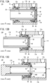
- a fluid pressure cylinder 10C shown in FIG. 13A is configured as a so-called single-acting cylinder. More specifically, the fluid pressure cylinder 10C is obtained by disposing a spring 154 between the packing 34 and the rod cover 16 in the fluid pressure cylinder 10A ( FIG. 1 ). In this case, the second port 12b is exposed to the atmosphere.
- the rod assembly 17A In the fluid pressure cylinder 10C, when pressurized fluid is supplied to the first pressure chamber 13a via the first port 12a, the rod assembly 17A is displaced (advanced) toward the rod cover 16 by the pressurized fluid and reaches the stroke end at the advanced position.
- the rod assembly 17A When the supply of the pressurized fluid to the first port 12a is stopped and the first port 12a is exposed to the atmosphere, the rod assembly 17A is displaced (retracted) toward the head cover 14 by the elastic biasing force of the spring 154 and reaches the stroke end at the retracted position.
- a fluid pressure cylinder 10D shown in FIG. 13B is also configured as a so-called single-acting cylinder. More specifically, the fluid pressure cylinder 10D is obtained by disposing a spring 154 between the packing 34 and the head cover 14 in the fluid pressure cylinder 10A ( FIG. 1 ). In this case, the first port 12a is exposed to the atmosphere.
- the rod assembly 17A In the fluid pressure cylinder 10D, when pressurized fluid is supplied to the second pressure chamber 13b via the second port 12b, the rod assembly 17A is displaced (retracted) toward the head cover 14 by the pressurized fluid and reaches the stroke end at the retracted position.
- the rod assembly 17A When the supply of the pressurized fluid to the second port 12b is stopped and the second port 12b is exposed to the atmosphere, the rod assembly 17A is displaced (advanced) toward the rod cover 16 by the elastic biasing force of the spring 154 and reaches the stroke end at the advanced position.
- a fluid pressure cylinder 10E shown in FIG. 13C is also configured as a so-called single-acting cylinder.
- the fluid pressure cylinder 10E has a rod assembly 17P.
- a damper member 40B attached to the base end portion of the rod member 20 has a circular ring shape.
- a rod end member 94 is attached to the distal end portion of the rod member 20.
- the rod end member 94 may be configured similarly to the rod end member 90 ( FIG. 11B ) or the rod end member 92 ( FIG. 11C ) described above.
- a spring 156 is inserted in the hollow portion of the rod member 20. The spring 156 is disposed between the rod end member 94 and the head cover 14.
- the fluid pressure cylinder 10E configured as above operates similarly to the fluid pressure cylinder 10D described above.
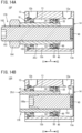
- a rod assembly 17Q of a fluid pressure cylinder 10F illustrated in FIG. 14A comprises a hollow rod member 20J having an internal thread portion 160 formed in the inner circumferential surface, the packing 34 attached to an outer circumferential part of the rod member 20J, and an adjustment bolt 162 inserted into the rod member 20J and screw-engaged with the rod member 20J.
- the adjustment bolt 162 has, formed on an outer circumference thereof, an external thread portion 163 configured to be screw-engaged with the internal thread portion 160.
- the adjustment bolt 162 protrudes from the rod member 20J toward the distal end (in the direction of the arrow X1).
- An adjustment nut 164 is screw-engaged onto the adjustment bolt 162 at a position closer to the distal end than the rod member 20J.
- the damper member 40 is attached to the base end portion of the rod member 20J.
- the retraction amount by which the rod member 20J is pulled or retracted into the cylinder tube 12 can be adjusted by adjusting the protrusion length by which the adjustment bolt 162 protrudes from the rod member 20J toward the head cover 14.
- a rod assembly 17R of a fluid pressure cylinder 10G illustrated in FIG. 14B adopts an adjustment bolt 166 shorter than the above-described adjustment bolt 162 ( FIG. 14A ).
- a distal end portion 166a of the adjustment bolt 166 is located inside the hollow portion of the rod member 20J.
- the distal end portion 166a of the adjustment bolt 166 is not provided with the external thread portion 163, and the outer diameter of the distal end portion 166a is smaller than the outer diameter of a portion provided with the external thread portion 163.
- the present invention is not limited to the above-described embodiments, and various modifications can be made as long as not departing from the scope of the present invention as defined by the appended claims.
- the present invention is applicable to fluid pressure cylinders provided with piston units and cylinder tubes having non-circular (quadrangular or elongated circular such as elliptical) cross-sections (for example, the rod assembly 17B in FIG. 3 ).
- the present invention is also applicable to multi-rod (such as dual rod) fluid pressure cylinders provided with a plurality of pistons and piston rods.
- the present invention is not limited to the fluid pressure cylinders used as actuators or the like, and is also applicable to different configurations of fluid pressure devices including pistons.
- the different configurations of fluid pressure devices equipped with pistons, to which the present invention is applicable include, for example, a valve device for switching channels by moving a valve element using a piston, a length-measurement cylinder for measuring length by displacing a piston connected to a piston rod serving as an input shaft, a sliding table connected to a piston via a piston rod and configured to be displaced by displacing the piston via the piston rod, and a chuck device for gripping a workpiece using a gripping part that opens and closes by displacing a piston and then converting the displacement of the piston.
Landscapes
- Engineering & Computer Science (AREA)
- General Engineering & Computer Science (AREA)
- Mechanical Engineering (AREA)
- Physics & Mathematics (AREA)
- Fluid Mechanics (AREA)
- Actuator (AREA)
- Sealing Devices (AREA)
- Vibration Dampers (AREA)
- Chemical & Material Sciences (AREA)
- Analytical Chemistry (AREA)
- Fluid-Damping Devices (AREA)
Description
- The present invention relates to a rod assembly reciprocating along a slide hole and a fluid pressure device.
- Conventionally, various devices are known as fluid pressure devices provided with pistons. For example, fluid pressure cylinders including pistons configured to be displaced by the effect of supplied pressurized fluid are well known as means (actuators) for transporting workpieces and the like. A typical fluid pressure cylinder includes a cylinder tube, a piston disposed inside the cylinder tube to be movable in the axial direction, and a piston rod connected to the piston (for example, see
JP 2014-114874 A
JP H11 132 204 A
CN 104 895 862 A describes a hydraulic oil cylinder with a displacement sensor. The hydraulic oil cylinder comprises a hollow piston rod with an inner end sealed. External threads are arranged at the outer end of the piston rod forming a threaded connection with an adapting seat. A sensor hole is formed on the outer end of the piston rod and a magneto strictive linear displacement sensor is arranged in that sensor hole.
DE 94 16 082 U1 describes a piston cylinder arrangement, wherein one end of the cylinder comprises a cylinder cover. A piston is provided in the cylinder, wherein a small gap is provided between the outer circumference of the piston and the inner circumference of the cylinder bore in order to reduce friction.
US 2006 0162 551 A1 describes a piston for a fluid operated power cylinder having two mutually coaxial sealing lips axially extending away from each other and being able to radially yield for sealing engagement with the piston running face of the power cylinder and adjacent to at least one piston end side an elastic buffer body serving for shock absorbing in the end of the stroke position of the piston.
US 2015 0354 608 A1 describes a drive unit of a fluid actuated linear drive including a piston rod, an annular drive piston seated coaxially on the piston rod and a buffer sleeve which is likewise seated coaxially on the piston rod. These elements are fixed by the same common weld joint.
US 2015 0226 325 A1 describes a piston unit of a working cylinder having a first and second coupling partner. The first coupling partner is a piston, while the second coupling partner is a piston rod. The piston rod is inserted axially into the piston. Both coupling partners comprise a groove laying opposite to each other, such that a spring-loaded coupling ring is able to secure both coupling partners with respect to each other.
GB 1 103 118 A
EP 0 093 859 A2 describes a piston for sensing the piston position in a non-touching manner. The piston comprises an annular magnet provided on a sleeve. The magnet abuts two profile discs. The magnet, profile discs and piston are covered by a sealing material 18. - A piston and a piston rod in a conventional fluid pressure device are assembled together by, for example, inserting one end portion of the piston rod into a hole formed in the central part of the piston and swaging or crimping (plastically deforming) the one end portion. The assembly requires specific tools or devices and thus is complicated.
- The present invention has been devised taking into consideration the aforementioned problems, and has the object of providing a rod assembly and a fluid pressure device capable of being assembled through a simplified process.
- The above objective is achieved by a rod assembly having the features of claim 1.
- Preferred embodiments of the invention are evident from the dependent claims.
- The rod member includes, in the outer circumferential part, a stopper receiving groove extending in a circumferential direction. A stopper member divided into a plurality of elements in the circumferential direction is installed into the stopper receiving groove. The packing covers the stopper member, and thus the stopper member supports the packing and is prevented from coming off the stopper receiving groove.
- The packing may also function as a damper configured to relieve impact occurring when the rod member reaches a stroke end.
- The rod member may have a hollow shape.
- A damper member configured to relieve impact occurring when the rod member reaches a stroke end may be attached to an end portion of the rod member, and the damper member may airtightly or liquid-tightly block up a hollow portion of the rod member.
- An outer circumferential part of the damper member may be attached to an inner circumferential part of the rod member.
- A supporting member configured to be harder than the damper member and to support the damper member may be disposed in the hollow portion of the rod member.
- The rod member may include a magnet receiving groove in an outer circumferential part thereof, and a magnet having an annular shape may be installed in the magnet receiving groove.
- The packing may be provided with at least one magnet receiving groove having a depth in an axial direction, and a magnet may be installed in the at least one magnet receiving groove.
- An outer circumference of the packing may have a non-circular shape, the at least one magnet receiving groove may include a plurality of magnet receiving grooves disposed at intervals in a circumferential direction, and the magnet may be installed in only part of the plurality of magnet receiving grooves.
- A fluid pressure device according to the present invention includes a body containing therein a slide hole and a rod assembly disposed so as to reciprocate along the slide hole, wherein the rod assembly includes a rod member and a packing attached to an outer circumferential part of the rod member and configured to slide along the slide hole.
- The fluid pressure device may be configured as a fluid pressure cylinder, a valve device, a length-measurement cylinder, a sliding table, or a chuck device.
- In accordance with the rod assembly and the fluid pressure device according to the present invention, the packing is attached to the outer circumferential part of the rod member. Thus, a hitherto-used hard piston member can be omitted, enabling easy assembly of the rod assembly. The assembly can be easily performed by hand without using any specific tools. Consequently, according to the present invention, the assembly work of the rod assembly can be simplified. Moreover, consumption of pressurized fluid (air or the like) when the rod member moves toward at least one side during the reciprocating motion inside the slide hole can be reduced by increasing the outer diameter of the rod member.
- The above-described object, features, and advantages will become more apparent from the following description of preferred embodiments in conjunction with the accompanying drawings.
-
-
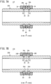
FIG. 1 is a cross-sectional view of a fluid pressure cylinder provided with a rod assembly according to a first embodiment; -
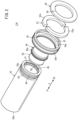
FIG. 2 is a perspective view of the rod assembly; -
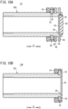
FIG. 3 is a cross-sectional view of a rod assembly according to a second embodiment; -
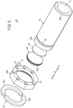
FIG. 4 is a perspective view of the rod assembly according to the second embodiment viewed from a side on which a packing lies; -
FIG. 5 is a perspective view of the rod assembly according to the second embodiment viewed from a side on which a rod member lies; -
FIG. 6A is a cross-sectional view of a rod assembly according to a third embodiment,FIG. 6B is a cross-sectional view of a rod assembly according to a fourth embodiment, andFIG. 6C is a cross-sectional view of a rod assembly according to a fifth embodiment; -
FIG. 7A is a cross-sectional view of a rod assembly according to a sixth embodiment, andFIG. 7B is a cross-sectional view of a rod assembly according to a seventh embodiment; -
FIG. 8A is a cross-sectional view of a rod assembly according to an eighth embodiment, andFIG. 8B is a cross-sectional view of a rod assembly according to a ninth embodiment; -
FIG. 9A is a cross-sectional view of a rod assembly according to a tenth embodiment, andFIG. 9B is a cross-sectional view of a rod assembly according to an eleventh embodiment; -
FIG. 10A is a cross-sectional view of a rod assembly according to a twelfth embodiment, andFIG. 10B is a cross-sectional view of a rod assembly according to a thirteenth embodiment; -
FIG. 11A is a cross-sectional view of a rod assembly according to a fourteenth embodiment,FIG. 11B is a perspective view of a rod end member of a first example, andFIG. 11C is a perspective view of a rod end member of a second example; -
FIG. 12 is a cross-sectional view of a fluid pressure cylinder provided with a rod assembly according to an example not covered by the present invention; -
FIG. 13A is a cross-sectional view of a fluid pressure cylinder configured as a single-acting cylinder,FIG. 13B is a cross-sectional view of another fluid pressure cylinder configured as a single-acting cylinder, andFIG. 13C is a cross-sectional view of another fluid pressure cylinder configured as a single-acting cylinder provided with a rod assembly according to a fifteenth embodiment; and -
FIG. 14A is a cross-sectional view of a fluid pressure cylinder provided with a rod assembly according to a sixteenth embodiment, and -
FIG. 14B is a cross-sectional view of a fluid pressure cylinder provided with a rod assembly according to an seventeenth embodiment. - Preferred embodiments of a rod assembly and a fluid pressure device according to the present invention will be described in detail below with reference to the accompanying drawings.
- A
fluid pressure cylinder 10A illustrated inFIG. 1 as an example of a fluid pressure device is provided with a cylinder tube 12 (body) having a hollow tubular shape, ahead cover 14 disposed at one end portion of thecylinder tube 12, arod cover 16 disposed at another end portion of thecylinder tube 12, and arod assembly 17A disposed to be able to reciprocate in the axial direction of thecylinder tube 12. Thefluid pressure cylinder 10A is used as an actuator for, for example, transporting a workpiece. - The
cylinder tube 12 is a tubular body composed of, for example, a metal material such as aluminum alloy and extending in the axial direction. In this embodiment, thecylinder tube 12 has a hollow cylindrical shape. Thecylinder tube 12 has afirst port 12a disposed adjacent to one end in the axial direction (i.e., an end located in the direction of an arrow X2), asecond port 12b disposed adjacent to another end in the axial direction (i.e., an end located in the direction of an arrow X1), and a slide hole 13 (cylinder chamber) communicating with thefirst port 12a and thesecond port 12b. - The
head cover 14 is a plate-shaped body composed of, for example, a metal material similar to that of thecylinder tube 12 and is disposed to block up the one end portion (the end portion located in the X2 direction) of thecylinder tube 12. The head cover 14 hermetically closes the one end portion of thecylinder tube 12. - The
rod cover 16 is a circular ring-shaped member composed of, for example, a metal material similar to that of thecylinder tube 12 and is disposed to block up the other end portion (the end portion located in the X1 direction) of thecylinder tube 12. An outerannular groove 24 is formed in an outer circumferential part of therod cover 16. An outer sealingmember 26 composed of an elastic material is installed into the outerannular groove 24 to seal a gap between the outer circumferential surface of therod cover 16 and the inner circumferential surface of theslide hole 13. - An inner
annular groove 28 is formed in an inner circumferential part of therod cover 16. An inner sealingmember 30 composed of an elastic material is installed into the innerannular groove 28 to seal a gap between the inner circumferential surface of therod cover 16 and the outer circumferential surface of arod member 20. Therod cover 16 is locked by astopper 32 secured to an inner circumferential part of thecylinder tube 12 adjacent to the other end of thecylinder tube 12. - The
rod assembly 17A includes therod member 20 extending in the axial direction of theslide hole 13 and a packing 34 attached to an outer circumferential part of therod member 20. Therod member 20 has a hollow shape (a hollow cylindrical shape in the first embodiment) and includes ahollow portion 21 passing through in the axial direction. - The
rod member 20 penetrates through therod cover 16. Adistal end portion 20b, which is the opposite end of oneend portion 20a (hereinafter referred to as "abase end portion 20a") of therod member 20, is exposed to the outside of theslide hole 13. The constituent material of therod member 20 includes, for example, metal materials such as carbon steel, stainless steel, and aluminum alloy, and hard resin. - The packing 34 is accommodated inside the cylinder tube 12 (slide hole 13) to be slidable in the axial direction and partitions the inside of the
slide hole 13 into afirst pressure chamber 13a adjacent to thefirst port 12a and asecond pressure chamber 13b adjacent to thesecond port 12b. In this embodiment, the packing 34 is attached to thebase end portion 20a of therod member 20. - The packing 34 is an annular member protruding radially outward from the
rod member 20. The outer diameter of the packing 34 is larger than the outer diameter of therod member 20. Therod member 20 is provided with an annularstopper receiving groove 50 and an annularmagnet receiving groove 49, which are formed in an outer circumferential part of the rod member in the vicinity of thebase end portion 20a so as to be spaced in the axial direction. - The packing 34 is a circular ring-shaped sealing member (for example, O-ring) composed of an elastic body and attached to the outer circumferential part of the
rod member 20, and is disposed to surround therod member 20. The constituent material of the packing 34 includes, for example, elastic materials such as rubber and elastomer (urethane rubber and the like). - The outer circumferential surface of the packing 34 airtightly or liquid-tightly contacts with the inner circumferential surface of the
slide hole 13 over the entire circumference. The inner circumferential surface of the packing 34 airtightly or liquid-tightly contacts with the outer circumferential part (outer circumferential surface) of therod member 20 over the entire circumference. Thus, the packing 34 airtightly or liquid-tightly separates thefirst pressure chamber 13a and thesecond pressure chamber 13b from each other inside theslide hole 13. - In this manner, the
rod assembly 17A includes the packing 34, which is attached to the outer circumferential part of therod member 20 so as to airtightly or liquid-tightly separate thefirst pressure chamber 13a and thesecond pressure chamber 13b from each other. Thus, unlike typical fluid pressure cylinders, the fluid pressure cylinder has a pistonless structure without a piston member made of a hard material. Alternatively, the packing 34 can be regarded as functioning as a piston in therod assembly 17A. - Moreover, the packing 34 also functions as a damper (first damper) relieving impact occurring when the rod member reaches a stroke end on the
rod cover 16 side. - The packing 34 is attached to a
stopper member 52 so as to cover thestopper member 52. Thestopper member 52 has a circular ring shape and is installed into thestopper receiving groove 50 of therod member 20. - The packing 34 has an L-shaped cross-section and includes a
packing body portion 34a covering a side of thestopper member 52 facing the rod cover 16 (a side located in the direction of the arrow X1) and acircumference covering portion 34b covering the outer circumference of thestopper member 52. Thecircumference covering portion 34b protrudes from an outer circumferential part of thepacking body portion 34a in the axial direction. - As shown in
FIG. 2 , thestopper member 52 includes a plurality of circumferentially-segmentedstopper elements 52a. Each of thestopper elements 52a is arc-shaped. In the first embodiment, thestopper member 52 is divided into halves and thus consists of the twostopper elements 52a of semicircular arcs. InFIG. 1 , the inner circumference of the stopper member 52 (inner circumferences of thestopper elements 52a) is installed into thestopper receiving groove 50. Thestopper member 52 is made of a hard material, for example, a material similar to the above-described material of therod member 20. - The
circumference covering portion 34b is attached to the outer circumference of thestopper member 52. Thus, the packing 34 is supported by thestopper member 52. Moreover, since the packing 34 is attached to thestopper member 52, thestopper member 52 is prevented from coming off thestopper receiving groove 50. - The
circumference covering portion 34b has an annular engaginggroove 35 formed in an inner circumferential part thereof. The outer circumference of thestopper member 52 engages with the annular engaginggroove 35 of thecircumference covering portion 34b. In a state where therod assembly 17A is disposed inside theslide hole 13, thecircumference covering portion 34b is pushed radially inward by the inner circumferential surface defining theslide hole 13. This prevents thecircumference covering portion 34b having the annular engaginggroove 35 from coming off the outer circumference of thestopper member 52. - The
rod member 20 and the packing 34 are rotatable relative to each other about an axis a1 of the packing 34. - During an assembly process of the
rod assembly 17A, thestopper member 52 and the packing 34 are attached to therod member 20 as follows. First, the twostopper elements 52a are individually attached to (fitted into) thestopper receiving groove 50 of therod member 20 so as to form theannular stopper member 52. Next, the packing 34 is moved on therod member 20 from thedistal end portion 20b side toward thebase end portion 20a side, and then the packing 34 covers the stopper member 52 (twostopper elements 52a). Thus, thestopper member 52 is prevented from coming off thestopper receiving groove 50, and the packing 34 is held at a predetermined position on the outer circumferential part of therod member 20. - A
magnet 48 is a circular ring-shaped member installed into the outer circumferential part (magnet receiving groove 49) of therod member 20. Themagnet 48 is elastically deformable. Themagnet 48 is a plastic magnet having a slit 54 (gap) at a location in the circumferential direction. Thus, themagnet 48 elastically deforms when being installed into themagnet receiving groove 49, enabling an easy installation. - The
magnet 48 is disposed at a position adjacent to the packing 34. An end surface of themagnet 48 facing the packing 34 is in contact with an end surface of the packing 34 facing themagnet 48. The end surface of themagnet 48 facing the packing 34 may not be in contact with the end surface of the packing 34 facing themagnet 48. - Magnetic sensors (not illustrated) are attached to the outer surface of the
cylinder tube 12 at positions corresponding to both stroke ends of the packing 34 and themagnet 48. The magnetic sensors detect magnetism generated by themagnet 48 to thereby detect the working position of therod assembly 17A. - A damper member 40 (second damper) relieving impact occurring when the rod member reaches a stroke end on the
head cover 14 side is disposed at thebase end portion 20a of therod member 20. Thedamper member 40 is attached to an inner circumferential part of thebase end portion 20a of therod member 20 and protrudes from anend surface 20c of therod member 20 located at thebase end portion 20a toward the head cover 14 (in the direction of the arrow X2). In the first embodiment, thedamper member 40 has a circular shape. - The
damper member 40 is provided with an annular (circular ring-shaped)flange portion 40a protruding radially outward. Theflange portion 40a engages with an annularengaging recess 58 formed in the inner circumferential part of thebase end portion 20a of therod member 20. The engagement between theflange portion 40a and the annular engagingrecess 58 prevents thedamper member 40 from coming off thebase end portion 20a of therod member 20. - The
rod member 20 has a steppedportion 60 formed on an inner circumferential part of thebase end portion 20a. A supportingmember 62 is disposed on the steppedportion 60. The supportingmember 62 is a circular plate-shaped member and is held between the steppedportion 60 and thedamper member 40. The supportingmember 62 supports thedamper member 40 and prevents thedamper member 40 from being bent by pressure from pressurized fluid. Thus, the supportingmember 62 is configured to be harder than thedamper member 40. The supportingmember 62 is made of a hard material, for example, a material similar to the material of the above-describedrod member 20. - In
FIG. 1 , an outer circumferential part of thedamper member 40 is in close contact with the inner circumferential part of therod member 20 over the entire circumference and thus airtightly or liquid-tightly closes an opening of therod member 20 at thebase end portion 20a. That is, thedamper member 40 also functions as a sealing member for airtightly or liquid-tightly blocking up thehollow portion 21 of therod member 20. - Next, the effects and advantages of the
fluid pressure cylinder 10A illustrated inFIG. 1 configured as above will be described. In thefluid pressure cylinder 10A, therod assembly 17A is reciprocated in the axial direction by the effect of pressurized fluid (for example, compressed air) introduced via thefirst port 12a or thesecond port 12b. - Specifically, to advance the
rod assembly 17A (move therod assembly 17A in the direction of the arrow X1), the pressurized fluid is supplied from a pressurized fluid supply source (not illustrated) to thefirst pressure chamber 13a via thefirst port 12a while thesecond port 12b is exposed to the atmosphere. This causes the pressurized fluid to push therod assembly 17A toward therod cover 16, whereby therod assembly 17A is advanced. - When the packing 34 comes into abutment against the end surface of the
rod cover 16, the advancing motion of therod assembly 17A stops. In this case, since the packing 34 is made of an elastic material, impact and impact noise occurring when therod assembly 17A reaches an advanced position (the stroke end on therod cover 16 side) are effectively prevented or reduced. - On the other hand, to retract the
rod assembly 17A (move therod assembly 17A in the direction of the arrow X2), the pressurized fluid is supplied from the pressurized fluid supply source (not illustrated) to thesecond pressure chamber 13b via thesecond port 12b while thefirst port 12a is exposed to the atmosphere. This causes the pressurized fluid to push therod assembly 17A toward thehead cover 14, whereby therod assembly 17A is retracted (returning action). - When the
damper member 40 comes into abutment against thehead cover 14, the retracting motion of therod assembly 17A stops. In this case, thedamper member 40 made of an elastic material prevents therod member 20 and the head cover 14 from coming into direct contact with each other. Thus, impact and impact noise occurring when therod assembly 17A reaches a retracted position (the stroke end on thehead cover 14 side) are effectively prevented or reduced. - In this case, the packing 34 is attached to the outer circumferential part of the
rod member 20 in therod assembly 17A according to this embodiment. Thus, a hitherto-used hard piston member can be omitted, enabling easy assembly of therod assembly 17A. The assembly can be easily performed by hand without using any specific tools. Consequently, therod assembly 17A of the present invention can simplify the assembly work. Moreover, by increasing the outer diameter of therod member 20, it is possible to reduce consumption of pressurized fluid (air or the like) when the rod member moves toward at least one side (when moving toward the head cover 14 (retracting) in the first embodiment) during the reciprocating motion inside theslide hole 13. - In this embodiment, the
rod member 20 has, formed in the outer circumferential part, thestopper receiving groove 50 extending in the circumferential direction, and thestopper member 52, which is circumferentially divided into the plurality of elements, is installed into thestopper receiving groove 50. In addition, the packing 34 covers thestopper member 52. Thus, the packing 34 is supported by thestopper member 52, and thestopper member 52 is prevented from coming off thestopper receiving groove 50. This structure enables the packing 34 to be easily attached to the outer circumferential part of therod member 20 and allows the attachment state to be stably maintained. - The packing 34 also functions as a damper for relieving impact occurring when the rod member reaches one of the stroke ends (on the
rod cover 16 side in the first embodiment). Thus, impact load is successfully prevented from being transmitted to therod member 20 when the rod member reaches the one of the stroke ends. - In this embodiment, the
rod member 20 has a hollow shape. This leads to a reduction in the weight of therod assembly 17A. In addition, the reduction in the weight of therod assembly 17A leads to a reduction in the consumption of the pressurized fluid, resulting in energy savings. - In this embodiment, the
rod member 20 and the packing 34 are rotatable relative to each other about the axis a1 of the packing 34. This conveniently allows therod member 20 to easily rotate during installation of thefluid pressure cylinder 10A in a facility. Moreover, as described below, therod member 20 is also rotatable in arod assembly 17B (FIG. 3 ) provided with apolygonal packing 34A. - In this embodiment, the
damper member 40 also functions as a sealing member for airtightly or liquid-tightly blocking up thehollow portion 21 of therod member 20. Thus, the number of parts can be reduced compared with a structure including a damper and a sealing member separately. - The present invention is not limited to the above circular packing 34, and is also applicable to the
polygonal packing 34A. Thus, instead of therod assembly 17A provided with thecircular packing 34, thefluid pressure cylinder 10A may adopt therod assembly 17B provided with thepolygonal packing 34A shown inFIGS. 3 to 5 . - As illustrated in
FIGS. 4 and5 , the outer circumference of thepacking 34A of therod assembly 17B has an octagonal shape. The inner circumference of the packing 34A has a circular shape. As shown inFIG. 5 , the packing 34A has a plurality ofmagnet receiving grooves 70 disposed at intervals in the circumferential direction. Specifically, the plurality ofmagnet receiving grooves 70 are formed in one surface of thepacking 34A and have a depth in the axial direction of thepacking 34A. Amagnet 72 is installed in each of themagnet receiving grooves 70. Themagnet 72 is, for example, a ferrite magnet, a rare earth magnet, or the like. - The other part of the
rod assembly 17B is configured similarly to therod assembly 17A. - The
rod assembly 17B yields effects similar to the effects of therod assembly 17A. For example, therod assembly 17B can also be easily assembled by hand without using any specific tools. - The above-described
rod assembly 17A (FIG. 1 ) adopts therod member 20 having a hollow structure. However, as inrod assemblies 17C to 17E respectively shown inFIGS. 6A to 6C ,rod members - The
rod assembly 17C inFIG. 6A adopts therod member 20A having a solid structure, instead of therod member 20 in therod assembly 17A (FIG. 1 ). - The
packing 34A of therod assembly 17D inFIG. 6B has amagnet holding portion 74 formed by extending thecircumference covering portion 34b of the packing 34 of therod assembly 17A (FIG. 1 ) in the axial direction so as to hold amagnet 48A (a magnet having a smaller outer diameter and a larger inner diameter than themagnet 48 ofFIG. 1 ) . - The
magnet 48A is held between themagnet holding portion 74 and an outer circumferential part of therod member 20B. A magnet-holdingannular groove 74a is formed in the inner circumferential surface of themagnet holding portion 74. The outer circumference of themagnet 48A is fitted (engaged) into the magnet-holdingannular groove 74a. Therod assembly 17D adopts therod member 20B without a magnet receiving groove in the outer circumferential part. - As in the
rod assembly 17E inFIG. 6C , therod member 20A provided with themagnet receiving groove 49 in an outer circumferential part and thepacking 34A provided with themagnet holding portion 74 may be combined. In this case, amagnet 48B (a magnet having a smaller outer diameter than themagnet 48 shown inFIG. 1 ) is held between themagnet holding portion 74 and themagnet receiving groove 49. - The above-described
rod assembly 17A (FIG. 1 ) adopts therod member 20, which elongates and protrudes toward only one side of the packing 34. However, as inrod assemblies FIGS. 7A, 7B ,rod members packings 34 andpackings 34B, respectively, may be adopted. - The
rod assembly 17F shown inFIG. 7A includes thehollow rod member 20C having the twostopper receiving grooves 50 and the onemagnet receiving groove 49 in an outer circumferential part and the twopackings 34 attached to the outer circumferential part of therod member 20C. Themagnet receiving groove 49 is disposed between the twostopper receiving grooves 50. The twostopper members 52 are installed in the respectivestopper receiving grooves 50. The twopackings 34 are attached to therespective stopper members 52. Themagnet 48 is disposed between the twopackings 34. - The
rod assembly 17G shown inFIG. 7B adopts thehollow rod member 20D without a magnet receiving groove in an outer circumferential part. The twopackings 34B each including acircumference covering portion 34c formed by extending thecircumference covering portion 34b of the packing 34 (FIG. 7A ) in the axial direction are attached to the outer circumferential part of therod member 20D. - The
circumference covering portion 34c of each packing 34B includes a magnet-holding steppedportion 34d. The twopackings 34B hold amagnet 48C (a magnet having a smaller outer diameter and a larger inner diameter than themagnet 48 illustrated inFIG. 7A ) between the magnet-holding steppedportions 34d to thereby regulate the axial movement of themagnet 48C and to cover the outer circumference of themagnet 48C with thecircumference covering portions 34c. - As in
rod assemblies 17H and 17I respectively shown inFIGS. 8A and 8B ,rod members packings 34 andpackings 34B, respectively, may be adopted. - In the
rod assembly 17A (FIG. 1 ), therod member 20 has thedamper member 40 at thebase end portion 20a. However, as in arod assembly 17J shown inFIG. 9A , therod member 20 may not be provided with any damper member at thebase end portion 20a. In this case, the opening of therod member 20 at thebase end portion 20a is airtightly or liquid-tightly closed by a sealingmember 76. - A
rod assembly 17K may be configured, as shown inFIG. 9B , by omitting themagnet 48 from therod assembly 17A (FIG. 1 ). Therod assembly 17K adopts arod member 20G without a magnet receiving groove in the outer circumferential part. - As in a
rod assembly 17L shown inFIG. 10A , arod member 20H having an annular wearring receiving groove 86 in an outer circumferential part may be adopted, and awear ring 88 made of a low friction material may be installed into the wearring receiving groove 86. Thewear ring 88 is an annular member for preventing the outer circumferential surface of themagnet 48 from coming into contact with the inner circumferential surface defining theslide hole 13. - The
wear ring 88 is made of a low friction material. Such a low friction material includes, for example, synthetic resins with a low friction and a high resistance to wear, such as polytetrafluoroethylene (PTFE) and metal materials (for example, bearing steel). - As in a
rod assembly 17M illustrated inFIG. 10B , a rod member 20I without a magnet, a damper member, or a wear ring may be adopted. - As in a
rod assembly 17N shown inFIG. 11A , arod end member 90 may be attached to the distal end portion of therod member 20. As illustrated inFIGS. 11A and 11B , therod end member 90 includes ashaft portion 90b having athread portion 90a (external thread) formed on the outer circumference and ahead portion 90c provided on an end of theshaft portion 90b. Theshaft portion 90b and thehead portion 90c are integrally molded. Thethread portion 90a is screw-engaged with an inner circumferential part of the distal end of thehollow rod member 20. Thehead portion 90c has, on an outer circumferential part thereof, a polygonaltool grip portion 90d gripped by a tightening tool. In this case, therod member 20 is also provided with a tool grip portion. - Instead of the
rod end member 90, arod end member 92 illustrated inFIG. 11C may be attached to the distal end portion of therod member 20. Therod end member 92 includes ashaft portion 92b having athread portion 92a (external thread) formed in the outer circumference and a polygonaltool insertion hole 92c formed in an end of theshaft portion 92b. - In an example not covered by the present invention, a
fluid pressure cylinder 10B shown inFIG. 12 comprises a cylinder tube 102 (body) having a hollow tubular shape, ahead cover 104 disposed at one end portion of thecylinder tube 102, and arod cover 106 disposed at another end portion of thecylinder tube 102. Thefluid pressure cylinder 10B further comprises arod assembly 170 disposed to be able to reciprocate with respect to thecylinder tube 102 and acushioning mechanism 110 relieving impact at both stroke ends. Therod assembly 170 comprises arod member 108 and the packing 34 attached to therod member 108. - The
cylinder tube 102 has a cylindrical body, and contains therein a slide hole 103 (cylinder chamber) closed by thehead cover 104 and therod cover 106. - A first stepped
portion 112 of thehead cover 104 is inserted into the one end portion of thecylinder tube 102 located in the direction of the arrow X2. A first centralhollow portion 116 and afirst port 118 communicating with the first centralhollow portion 116 are formed in thehead cover 104. Pressurized fluid is supplied and discharged via thefirst port 118. - A second stepped
portion 120 of therod cover 106 is inserted into the other end portion of thecylinder tube 102 located in the direction of the arrow X1. A second centralhollow portion 124 and asecond port 126 communicating with the second centralhollow portion 124 are formed in therod cover 106. Pressurized fluid is supplied and discharged via thesecond port 126. A ring-shapedbush 130 and a ring-shapedpacking 132 are disposed on an inner circumferential part of therod cover 106. - The packing 34 is attached to an outer circumferential part of one end portion (hereinafter referred to as "
base end portion 108a") of therod member 108. The packing 34 is disposed at an end portion of a second cushioning member 142 (described below) adjacent to thehead cover 104. The outer circumferential surface of the packing 34 is in contact with the inner circumferential surface defining theslide hole 103 over the entire circumference. The inner circumferential surface of the packing 34 is in contact with the outer circumferential surface of thesecond cushioning member 142 over the entire circumference. Therod member 108 includes thestopper receiving groove 50 and themagnet receiving groove 49 formed in an outer circumferential part. Thestopper member 52 is installed in thestopper receiving groove 50. Themagnet 48 is installed in themagnet receiving groove 49. - A
damper member 40A is attached to thebase end portion 108a of therod member 108. Thedamper member 40A is obtained by modifying the damper member 40 (FIG. 1 ) so as to be hollow. - The
cushioning mechanism 110 includes afirst cushioning member 140 and the second cushioning member 142 (cushion ring), which are provided on the movable part (rod member 108), and a ring-shapedfirst cushion seal 144 and a ring-shapedsecond cushion seal 146, which are composed of elastic members and provided on the fixed part (thehead cover 104 and the rod cover 106). - The
first cushioning member 140 is disposed at an end of therod member 108 located in the direction of the arrow X2 so as to be coaxial with therod member 108. Specifically, thefirst cushioning member 140 has a smaller diameter than therod member 108 and protrudes from the supportingmember 62 and thedamper member 40A in the direction of the arrow X2. Thefirst cushioning member 140 has a hollow or solid cylindrical shape. The outer diameter of thefirst cushioning member 140 is smaller than the outer diameter of thedamper member 40A. - The
first cushioning member 140 may be a part integrated with therod member 108 or may be a separate part joined to therod member 108. In the case where thefirst cushioning member 140 is a part separate from therod member 108, thefirst cushioning member 140 may be joined to therod member 108 by joining means such as welding, bonding, and screwing. - The
first cushion seal 144 is held by the inner circumference of a ring-shapedfirst holder 148. Thefirst holder 148 is secured to the inner circumference of the first steppedportion 112 of thehead cover 104. While thefirst cushioning member 140 is not inserted into ahole 148a of thefirst holder 148, theslide hole 103 and the first centralhollow portion 116 communicate with each other via thehole 148a. When thefirst cushioning member 140 is inserted into thehole 148a of thefirst holder 148, thefirst cushion seal 144 is brought into sliding contact with the outer circumferential surface of thefirst cushioning member 140 over the entire circumference. - The
second cushioning member 142 is disposed adjacent to the packing 34 and coaxially with therod member 108. Thesecond cushioning member 142 is a ring-shaped member having a larger diameter than therod member 108 and a smaller diameter than the packing 34, and is joined to the outer circumferential surface of therod member 108 by, for example, welding, bonding, or the like. In the example not covered by the present invention ofFIG. 12 , the outer diameter of thesecond cushioning member 142 is slightly larger than the outer diameter of therod member 108. - The
second cushion seal 146 is held by the inner circumference of a ring-shapedsecond holder 150. Thesecond holder 150 is secured to the inner circumference of the second steppedportion 120 of therod cover 106. While thesecond cushioning member 142 is not inserted into ahole 150a of thesecond holder 150, theslide hole 103 and the second centralhollow portion 124 communicate with each other via thehole 150a. When thesecond cushioning member 142 is inserted into thehole 150a of thesecond holder 150, thesecond cushion seal 146 is brought into sliding contact with the outer circumferential surface of thesecond cushioning member 142 over the entire circumference. - Next, the effects of the
fluid pressure cylinder 10B configured as above will be described. In the description below, air (compressed air) is used as pressurized fluid. However, gas other than air may be used. - In the
fluid pressure cylinder 10B, therod assembly 170 is moved back and forth along theslide hole 103 in the axial direction by the effect of pressurized fluid introduced via thefirst port 118 or thesecond port 126. - Specifically, while the
rod assembly 170 is located at a retracted position shown in the example not covered by the present invention ofFig. 12 , thesecond port 126 is exposed to the atmosphere, and air is supplied from a pressurized fluid supply source (not illustrated) to afirst pressure chamber 103a via thefirst port 118, the first centralhollow portion 116, and thehole 148a. This causes therod assembly 170 to be displaced (advanced) toward therod cover 106. In this case, the air inside asecond pressure chamber 103b is discharged from thesecond port 126 via thehole 150a of thesecond holder 150 and the second centralhollow portion 124. - When the packing 34 comes into abutment against the
second holder 150, the advancing motion of therod assembly 170 stops. - When the
rod assembly 170 approaches an advanced position, thesecond cushioning member 142 is inserted into thehole 150a of thesecond holder 150. This causes the inner circumference of thesecond cushion seal 146 to come into contact with the outer circumferential surface of thesecond cushioning member 142 and thus creates an airtight seal at the contact area. - As a result, an air cushion is formed in the
second pressure chamber 103b. The air cushion in thesecond pressure chamber 103b serves as displacement resistance of therod assembly 170 and decelerates the displacement of therod assembly 170 in the vicinity of the stroke end on therod cover 106 side. Consequently, impact occurring when therod assembly 170 reaches the stroke end is further relieved. The air is discharged to thesecond port 126 via a small hole (not illustrated) by a small amount. - On the other hand, while the
rod assembly 170 is located at the advanced position (stroke end on therod cover 106 side), thefirst port 118 is exposed to the atmosphere, and air is supplied from the pressurized fluid supply source (not illustrated) to thesecond pressure chamber 103b via thesecond port 126, the second centralhollow portion 124, and thehole 150a. This causes therod assembly 170 to be displaced (retracted) toward thehead cover 104. In this case, the air inside thefirst pressure chamber 103a is discharged from thefirst port 118 via thehole 148a of thefirst holder 148 and the first centralhollow portion 116. When thedamper member 40A comes into abutment against thefirst holder 148, the retracting motion of therod assembly 170 stops. - When the
rod assembly 170 approaches the retracted position, thefirst cushioning member 140 is inserted into thehole 148a of thefirst holder 148. This causes the inner circumference of thefirst cushion seal 144 to come into contact with the outer circumferential surface of thefirst cushioning member 140 and thus creates an airtight seal at the contact area. - As a result, an air cushion is formed in the
first pressure chamber 103a. The air cushion in thefirst pressure chamber 103a serves as displacement resistance during the displacement of therod assembly 170 toward thehead cover 104 and decelerates the displacement of therod assembly 170 in the vicinity of the stroke end on thehead cover 104 side. Consequently, impact occurring when therod assembly 170 reaches the stroke end is further relieved. - A fluid pressure cylinder 10C shown in
FIG. 13A is configured as a so-called single-acting cylinder. More specifically, the fluid pressure cylinder 10C is obtained by disposing aspring 154 between the packing 34 and therod cover 16 in thefluid pressure cylinder 10A (FIG. 1 ). In this case, thesecond port 12b is exposed to the atmosphere. - In the fluid pressure cylinder 10C, when pressurized fluid is supplied to the
first pressure chamber 13a via thefirst port 12a, therod assembly 17A is displaced (advanced) toward therod cover 16 by the pressurized fluid and reaches the stroke end at the advanced position. When the supply of the pressurized fluid to thefirst port 12a is stopped and thefirst port 12a is exposed to the atmosphere, therod assembly 17A is displaced (retracted) toward thehead cover 14 by the elastic biasing force of thespring 154 and reaches the stroke end at the retracted position. - A
fluid pressure cylinder 10D shown inFIG. 13B is also configured as a so-called single-acting cylinder. More specifically, thefluid pressure cylinder 10D is obtained by disposing aspring 154 between the packing 34 and thehead cover 14 in thefluid pressure cylinder 10A (FIG. 1 ). In this case, thefirst port 12a is exposed to the atmosphere. - In the
fluid pressure cylinder 10D, when pressurized fluid is supplied to thesecond pressure chamber 13b via thesecond port 12b, therod assembly 17A is displaced (retracted) toward thehead cover 14 by the pressurized fluid and reaches the stroke end at the retracted position. When the supply of the pressurized fluid to thesecond port 12b is stopped and thesecond port 12b is exposed to the atmosphere, therod assembly 17A is displaced (advanced) toward therod cover 16 by the elastic biasing force of thespring 154 and reaches the stroke end at the advanced position. - A
fluid pressure cylinder 10E shown inFIG. 13C is also configured as a so-called single-acting cylinder. Thefluid pressure cylinder 10E has arod assembly 17P. In therod assembly 17P, adamper member 40B attached to the base end portion of therod member 20 has a circular ring shape. - A
rod end member 94 is attached to the distal end portion of therod member 20. Therod end member 94 may be configured similarly to the rod end member 90 (FIG. 11B ) or the rod end member 92 (FIG. 11C ) described above. Aspring 156 is inserted in the hollow portion of therod member 20. Thespring 156 is disposed between therod end member 94 and thehead cover 14. Thefluid pressure cylinder 10E configured as above operates similarly to thefluid pressure cylinder 10D described above. - A
rod assembly 17Q of afluid pressure cylinder 10F illustrated inFIG. 14A comprises ahollow rod member 20J having aninternal thread portion 160 formed in the inner circumferential surface, the packing 34 attached to an outer circumferential part of therod member 20J, and anadjustment bolt 162 inserted into therod member 20J and screw-engaged with therod member 20J. Theadjustment bolt 162 has, formed on an outer circumference thereof, anexternal thread portion 163 configured to be screw-engaged with theinternal thread portion 160. Theadjustment bolt 162 protrudes from therod member 20J toward the distal end (in the direction of the arrow X1). Anadjustment nut 164 is screw-engaged onto theadjustment bolt 162 at a position closer to the distal end than therod member 20J. Thedamper member 40 is attached to the base end portion of therod member 20J. - According to the
rod assembly 17Q configured as above, the retraction amount by which therod member 20J is pulled or retracted into thecylinder tube 12 can be adjusted by adjusting the protrusion length by which theadjustment bolt 162 protrudes from therod member 20J toward thehead cover 14. - A
rod assembly 17R of afluid pressure cylinder 10G illustrated inFIG. 14B adopts anadjustment bolt 166 shorter than the above-described adjustment bolt 162 (FIG. 14A ). In a state where theadjustment bolt 166 protrudes outside from therod member 20J toward thehead cover 14, adistal end portion 166a of theadjustment bolt 166 is located inside the hollow portion of therod member 20J. Thedistal end portion 166a of theadjustment bolt 166 is not provided with theexternal thread portion 163, and the outer diameter of thedistal end portion 166a is smaller than the outer diameter of a portion provided with theexternal thread portion 163. - The present invention is not limited to the above-described embodiments, and various modifications can be made as long as not departing from the scope of the present invention as defined by the appended claims. For example, the present invention is applicable to fluid pressure cylinders provided with piston units and cylinder tubes having non-circular (quadrangular or elongated circular such as elliptical) cross-sections (for example, the
rod assembly 17B inFIG. 3 ). Moreover, the present invention is also applicable to multi-rod (such as dual rod) fluid pressure cylinders provided with a plurality of pistons and piston rods. - Yet moreover, the present invention is not limited to the fluid pressure cylinders used as actuators or the like, and is also applicable to different configurations of fluid pressure devices including pistons. The different configurations of fluid pressure devices equipped with pistons, to which the present invention is applicable, include, for example, a valve device for switching channels by moving a valve element using a piston, a length-measurement cylinder for measuring length by displacing a piston connected to a piston rod serving as an input shaft, a sliding table connected to a piston via a piston rod and configured to be displaced by displacing the piston via the piston rod, and a chuck device for gripping a workpiece using a gripping part that opens and closes by displacing a piston and then converting the displacement of the piston.
Claims (11)
- A rod assembly (17A to 17R) configured to reciprocate along a slide hole (13, 103) of a fluid pressure device, comprising:a rod member (20, 20A to 20J, 108); anda packing (34, 34A, 34B) composed of an elastic material, attached to an outer circumferential part of the rod member (20, 20A to 20J, 108) with an inner circumferential part of the packing (34, 34A, 34B) airtightly or liquid-tightly contacting said outer circumferential part of the rod member (20, 20A to 20J, 108) and configured to slide along the slide hole (13, 103) with an outer circumferential part of the packing (34, 34A, 34B) airtightly or liquid-tightly contacting with an inner circumferential part of the slide hole (13, 103)whereinthe rod member (20, 20A to 20J, 108) includes, in the outer circumferential part, a stopper receiving groove (50) extending in a circumferential direction;a stopper member (52) divided into a plurality of elements in the circumferential direction is installed into the stopper receiving groove (50) ;the packing (34) has an L-shaped cross-section and includes a packing body portion (34A) which covers a side of the stopper member (52) facing a rod cover (16) of the fluid pressure device which the rod member (20, 20A to 20J, 108) penetrates through when the rod assembly is disposed in the fluid pressure device and a circumference covering portion (34B) which protrudes from an outer circumferential part of the packing body portion (34A) in the axial direction to cover an outer circumference of the stopper member (52), andthe circumference covering portion (34B) has an annular engaging groove (35) formed in an inner circumferential part thereof, the annular engaging groove (35) being engaged with the stopper member (52).
- The rod assembly (17A to 17R) according to claim 1,
wherein the packing (34, 34A, 34B) also functions as a damper configured to relieve impact occurring when the rod member reaches a stroke end. - The rod assembly according to claim 1, wherein the rod member has a hollow shape.
- The rod assembly according to claim 3, wherein:a damper member (40, 40A, 40B) configured to relieve impact occurring when the rod member reaches a stroke end is attached to an end portion of the rod member; andthe damper member (40, 40A, 40B) airtightly or liquid-tightly blocks up a hollow portion of the rod member.
- The rod assembly according to claim 4, wherein an outer circumferential part of the damper member (40, 40A, 40B) is attached to an inner circumferential part of the rod member.
- The rod assembly according to claim 4, wherein a supporting member (62) configured to be harder than the damper member (40, 40A, 40B) and to support the damper member (40, 40A, 40B) is disposed in the hollow portion of the rod member.
- The rod assembly according to claim 1, wherein:the rod member includes a magnet receiving groove (49) in an outer circumferential part thereof; anda magnet (48, 48A) having an annular shape is installed in the magnet receiving groove (49).
- The rod assembly (17B) according to claim 1, wherein:the packing (34A) is provided with at least one magnet receiving groove (70) having a depth in an axial direction; anda magnet (72) is installed in the at least one magnet receiving groove (70).
- The rod assembly (17B) according to claim 8, wherein:an outer circumference of the packing (34A) has a non-circular shape;wherein the packing (34A) comprises a plurality of magnet receiving grooves (70) disposed at intervals in a circumferential direction; andthe magnet (72) is installed in only part of the plurality of magnet receiving grooves (70).
- A fluid pressure device comprising:
a body containing therein a slide hole (13, 103); and a rod assembly according to any of claims 1 to 9. - The fluid pressure device according to claim 10,
wherein the fluid pressure device is configured as a fluid pressure cylinder (10A to 10G), a valve device, a length-measurement cylinder, a sliding table, or a chuck device.
Applications Claiming Priority (2)
| Application Number | Priority Date | Filing Date | Title |
|---|---|---|---|
| JP2016236470A JP6598079B2 (en) | 2016-12-06 | 2016-12-06 | Rod assembly and fluid pressure device |
| PCT/JP2017/040680 WO2018105315A1 (en) | 2016-12-06 | 2017-11-13 | Rod assembly and fluid pressure device |
Publications (3)
| Publication Number | Publication Date |
|---|---|
| EP3553327A1 EP3553327A1 (en) | 2019-10-16 |
| EP3553327A4 EP3553327A4 (en) | 2020-07-29 |
| EP3553327B1 true EP3553327B1 (en) | 2024-01-24 |
Family
ID=62491183
Family Applications (1)
| Application Number | Title | Priority Date | Filing Date |
|---|---|---|---|
| EP17878720.6A Active EP3553327B1 (en) | 2016-12-06 | 2017-11-13 | Rod assembly and fluid pressure device |
Country Status (10)
| Country | Link |
|---|---|
| US (1) | US11143214B2 (en) |
| EP (1) | EP3553327B1 (en) |
| JP (1) | JP6598079B2 (en) |
| KR (1) | KR102257340B1 (en) |
| CN (1) | CN110050129B (en) |
| BR (1) | BR112019011485A2 (en) |
| MX (1) | MX2019006430A (en) |
| RU (1) | RU2019120895A (en) |
| TW (1) | TWI659162B (en) |
| WO (1) | WO2018105315A1 (en) |
Families Citing this family (5)
| Publication number | Priority date | Publication date | Assignee | Title |
|---|---|---|---|---|
| DE102016007593A1 (en) * | 2016-06-21 | 2017-12-21 | Liebherr-Components Kirchdorf GmbH | Method for producing a piston rod unit and piston rod unit |
| JP6751916B2 (en) * | 2018-03-23 | 2020-09-09 | Smc株式会社 | Fluid pressure cylinder |
| CN112689714B (en) * | 2018-09-13 | 2023-05-16 | Smc 株式会社 | Fluid pressure cylinder |
| CN110864030B (en) * | 2019-11-01 | 2024-11-05 | 江南工业集团有限公司 | A closed product pressure test control device and control method |
| CN111911631B (en) * | 2020-08-10 | 2022-06-10 | 常德市联嘉机械有限公司 | Bidirectional piston sealing structure used in high-pressure environment |
Family Cites Families (35)
| Publication number | Priority date | Publication date | Assignee | Title |
|---|---|---|---|---|
| US2493602A (en) * | 1947-12-31 | 1950-01-03 | Vance C Sterrett | Pressure fluid motor |
| US2981232A (en) * | 1957-04-10 | 1961-04-25 | Renault | Differential pressure pneumatic jacks adapted for automatic return to initial position |
| GB1103118A (en) * | 1964-02-13 | 1968-02-14 | Walter Douglass | Improvements in or relating to fluid actuated magnetic switches |
| DE2730112C2 (en) * | 1977-07-04 | 1982-04-15 | Festo-Maschinenfabrik Gottlieb Stoll, 7300 Esslingen | Piston arrangement, especially for dry running compressors |
| JPS59501555A (en) * | 1981-11-19 | 1984-08-30 | スペツイアルノエ コンストルクトルスコ− チエフノロギチエスコエ ビユ−ロ− グラフモスインジエストロヤ プリ モスゴリスポルコメ | hydraulic jack |
| DE8209420U1 (en) * | 1982-04-02 | 1983-09-15 | Robert Bosch Gmbh, 7000 Stuttgart | PISTON FOR CONTACTLESS PISTON POSITION SENSING |
| JPH01171905U (en) * | 1988-05-26 | 1989-12-06 | ||
| JP2531830Y2 (en) * | 1989-09-01 | 1997-04-09 | シーケーディ 株式会社 | Cylinder buffer structure |
| JPH0380109U (en) * | 1989-12-05 | 1991-08-16 | ||
| JPH0632495U (en) * | 1992-09-28 | 1994-04-28 | 日本輸送機株式会社 | Shock absorber in full free mast system |
| DE9416082U1 (en) * | 1994-10-06 | 1994-12-08 | Kuhnke GmbH, 23714 Malente | Piston-cylinder arrangement |
| DE29607993U1 (en) * | 1996-05-03 | 1996-08-01 | Festo Kg, 73734 Esslingen | Piston for a working cylinder |
| IT1285781B1 (en) | 1996-10-11 | 1998-06-18 | Giacomo Bardoni | ELECTRO-PNEUMATIC ACTUATOR |
| US5947001A (en) * | 1997-04-24 | 1999-09-07 | Turn-Act, Inc. | Molded piston |
| JPH11132204A (en) | 1997-10-31 | 1999-05-18 | Taiyo Ltd | Cylinder device |
| JP3469525B2 (en) * | 2000-03-03 | 2003-11-25 | Smc株式会社 | Pneumatic rotary actuator with cushion mechanism |
| JP3803068B2 (en) * | 2001-06-05 | 2006-08-02 | 有限会社有泉設計 | Fluid pressure cylinder |
| DE202005001117U1 (en) * | 2005-01-25 | 2005-03-31 | Festo Ag & Co | Piston and thus equipped working cylinder |
| DE202005005508U1 (en) * | 2005-04-07 | 2005-06-02 | Festo Ag & Co. | Piston for a liquid-operated adjusting device, especially a linear drive or shock absorber comprises a permanent magnet arrangement segmented in its peripheral direction and having magnet segments |
| CA2507149A1 (en) * | 2005-05-12 | 2006-11-12 | P & M Design & Consulting Ltd. | Pneumatic cylinder |
| JP4453023B2 (en) * | 2005-06-20 | 2010-04-21 | Smc株式会社 | Fluid pressure cylinder with position detector |
| KR100777412B1 (en) * | 2006-07-11 | 2007-11-19 | 한국기계연구원 | Cylinder with relative distance measurement of piston rod |
| DE102006040085A1 (en) * | 2006-08-28 | 2008-03-20 | Zimmer, Günther | Cost-effective to produce pneumatic retarding device |
| DE102007016431A1 (en) * | 2007-04-05 | 2008-10-09 | Festo Ag & Co. Kg | Fluid operated linear actuator |
| JP5212773B2 (en) * | 2007-09-11 | 2013-06-19 | Smc株式会社 | Fluid pressure cylinder |
| JP2013024302A (en) * | 2011-07-19 | 2013-02-04 | Komatsu Ltd | Hydraulic cylinder |
| CN102518618A (en) * | 2011-12-27 | 2012-06-27 | 山东天一液压科技股份有限公司 | Hydraulic cylinder |
| CN202646222U (en) * | 2012-05-23 | 2013-01-02 | 三一重工股份有限公司 | Oil cylinder and hydraulic system |
| JP6028994B2 (en) * | 2012-06-18 | 2016-11-24 | Smc株式会社 | Fluid pressure cylinder |
| DE202012008999U1 (en) * | 2012-09-19 | 2014-01-15 | Bümach Engineering International B.V. | Piston unit of a working cylinder |
| JP6103349B2 (en) | 2012-12-10 | 2017-03-29 | Smc株式会社 | Fluid pressure cylinder |
| DE102013008408A1 (en) * | 2013-05-16 | 2014-11-20 | Festo Ag & Co. Kg | Drive unit of a fluid-actuated linear drive and method for its production |
| CN204083234U (en) * | 2014-08-26 | 2015-01-07 | 优泰科(苏州)密封技术有限公司 | A kind of piston seal |
| CN104895862B (en) * | 2015-05-18 | 2017-01-25 | 无锡亿利大机械有限公司 | Hydraulic oil cylinder with displacement sensor |
| CN205118244U (en) * | 2015-10-28 | 2016-03-30 | 上虞市神龙铝塑制品有限公司 | Piston rod and piston seal structure |
-
2016
- 2016-12-06 JP JP2016236470A patent/JP6598079B2/en active Active
-
2017
- 2017-11-13 EP EP17878720.6A patent/EP3553327B1/en active Active
- 2017-11-13 US US16/466,549 patent/US11143214B2/en active Active
- 2017-11-13 RU RU2019120895A patent/RU2019120895A/en unknown
- 2017-11-13 BR BR112019011485A patent/BR112019011485A2/en not_active Application Discontinuation
- 2017-11-13 MX MX2019006430A patent/MX2019006430A/en unknown
- 2017-11-13 KR KR1020197019428A patent/KR102257340B1/en active Active
- 2017-11-13 CN CN201780075333.2A patent/CN110050129B/en active Active
- 2017-11-13 WO PCT/JP2017/040680 patent/WO2018105315A1/en not_active Ceased
- 2017-12-01 TW TW106142187A patent/TWI659162B/en active
Also Published As
| Publication number | Publication date |
|---|---|
| RU2019120895A (en) | 2021-01-12 |
| KR102257340B1 (en) | 2021-05-27 |
| WO2018105315A1 (en) | 2018-06-14 |
| BR112019011485A2 (en) | 2019-10-22 |
| CN110050129B (en) | 2021-01-26 |
| JP6598079B2 (en) | 2019-10-30 |
| EP3553327A4 (en) | 2020-07-29 |
| RU2019120895A3 (en) | 2021-01-12 |
| MX2019006430A (en) | 2019-08-21 |
| TWI659162B (en) | 2019-05-11 |
| EP3553327A1 (en) | 2019-10-16 |
| CN110050129A (en) | 2019-07-23 |
| KR20190089992A (en) | 2019-07-31 |
| US11143214B2 (en) | 2021-10-12 |
| JP2018091440A (en) | 2018-06-14 |
| TW201827717A (en) | 2018-08-01 |
| US20200072254A1 (en) | 2020-03-05 |
Similar Documents
| Publication | Publication Date | Title |
|---|---|---|
| EP3553327B1 (en) | Rod assembly and fluid pressure device | |
| US10851813B2 (en) | Method for producing piston assembly and hydraulic fluid device | |
| KR102291549B1 (en) | hydraulic cylinder | |
| KR102257341B1 (en) | Shaft connection structure and fluid pressure device | |
| US10718360B2 (en) | Hydraulic fluid device | |
| US11079017B2 (en) | Hydraulic cylinder | |
| US11371538B2 (en) | Fluid pressure cylinder | |
| US11280409B2 (en) | Method for producing piston assembly and hydraulic fluid device | |
| US11215204B2 (en) | Piston unit and hydraulic cylinder | |
| US11067173B2 (en) | Piston assembly and fluid pressure device | |
| WO2018105314A1 (en) | Piston assembly and fluid pressure device | |
| JP2001173610A (en) | Rodless cylinder |
Legal Events
| Date | Code | Title | Description |
|---|---|---|---|
| STAA | Information on the status of an ep patent application or granted ep patent |
Free format text: STATUS: THE INTERNATIONAL PUBLICATION HAS BEEN MADE |
|
| PUAI | Public reference made under article 153(3) epc to a published international application that has entered the european phase |
Free format text: ORIGINAL CODE: 0009012 |
|
| STAA | Information on the status of an ep patent application or granted ep patent |
Free format text: STATUS: REQUEST FOR EXAMINATION WAS MADE |
|
| 17P | Request for examination filed |
Effective date: 20190703 |
|
| AK | Designated contracting states |
Kind code of ref document: A1 Designated state(s): AL AT BE BG CH CY CZ DE DK EE ES FI FR GB GR HR HU IE IS IT LI LT LU LV MC MK MT NL NO PL PT RO RS SE SI SK SM TR |
|
| AX | Request for extension of the european patent |
Extension state: BA ME |
|
| DAV | Request for validation of the european patent (deleted) | ||
| DAX | Request for extension of the european patent (deleted) | ||
| A4 | Supplementary search report drawn up and despatched |
Effective date: 20200630 |
|
| RIC1 | Information provided on ipc code assigned before grant |
Ipc: F15B 15/22 20060101ALI20200624BHEP Ipc: F15B 15/14 20060101AFI20200624BHEP |
|
| STAA | Information on the status of an ep patent application or granted ep patent |
Free format text: STATUS: EXAMINATION IS IN PROGRESS |
|
| 17Q | First examination report despatched |
Effective date: 20210810 |
|
| GRAP | Despatch of communication of intention to grant a patent |
Free format text: ORIGINAL CODE: EPIDOSNIGR1 |
|
| STAA | Information on the status of an ep patent application or granted ep patent |
Free format text: STATUS: GRANT OF PATENT IS INTENDED |
|
| INTG | Intention to grant announced |
Effective date: 20230914 |
|
| GRAS | Grant fee paid |
Free format text: ORIGINAL CODE: EPIDOSNIGR3 |
|
| GRAA | (expected) grant |
Free format text: ORIGINAL CODE: 0009210 |
|
| STAA | Information on the status of an ep patent application or granted ep patent |
Free format text: STATUS: THE PATENT HAS BEEN GRANTED |
|
| AK | Designated contracting states |
Kind code of ref document: B1 Designated state(s): AL AT BE BG CH CY CZ DE DK EE ES FI FR GB GR HR HU IE IS IT LI LT LU LV MC MK MT NL NO PL PT RO RS SE SI SK SM TR |
|
| REG | Reference to a national code |
Ref country code: GB Ref legal event code: FG4D |
|
| REG | Reference to a national code |
Ref country code: CH Ref legal event code: EP |
|
| REG | Reference to a national code |
Ref country code: DE Ref legal event code: R096 Ref document number: 602017078796 Country of ref document: DE |
|
| REG | Reference to a national code |
Ref country code: IE Ref legal event code: FG4D |
|
| REG | Reference to a national code |
Ref country code: LT Ref legal event code: MG9D |
|
| REG | Reference to a national code |
Ref country code: NL Ref legal event code: MP Effective date: 20240124 |
|
| PG25 | Lapsed in a contracting state [announced via postgrant information from national office to epo] |
Ref country code: NL Free format text: LAPSE BECAUSE OF FAILURE TO SUBMIT A TRANSLATION OF THE DESCRIPTION OR TO PAY THE FEE WITHIN THE PRESCRIBED TIME-LIMIT Effective date: 20240124 |
|
| PG25 | Lapsed in a contracting state [announced via postgrant information from national office to epo] |
Ref country code: NL Free format text: LAPSE BECAUSE OF FAILURE TO SUBMIT A TRANSLATION OF THE DESCRIPTION OR TO PAY THE FEE WITHIN THE PRESCRIBED TIME-LIMIT Effective date: 20240124 |
|
| PG25 | Lapsed in a contracting state [announced via postgrant information from national office to epo] |
Ref country code: IS Free format text: LAPSE BECAUSE OF FAILURE TO SUBMIT A TRANSLATION OF THE DESCRIPTION OR TO PAY THE FEE WITHIN THE PRESCRIBED TIME-LIMIT Effective date: 20240524 |
|
| PG25 | Lapsed in a contracting state [announced via postgrant information from national office to epo] |
Ref country code: LT Free format text: LAPSE BECAUSE OF FAILURE TO SUBMIT A TRANSLATION OF THE DESCRIPTION OR TO PAY THE FEE WITHIN THE PRESCRIBED TIME-LIMIT Effective date: 20240124 |
|
| PG25 | Lapsed in a contracting state [announced via postgrant information from national office to epo] |
Ref country code: GR Free format text: LAPSE BECAUSE OF FAILURE TO SUBMIT A TRANSLATION OF THE DESCRIPTION OR TO PAY THE FEE WITHIN THE PRESCRIBED TIME-LIMIT Effective date: 20240425 |
|
| REG | Reference to a national code |
Ref country code: AT Ref legal event code: MK05 Ref document number: 1652396 Country of ref document: AT Kind code of ref document: T Effective date: 20240124 |
|
| PG25 | Lapsed in a contracting state [announced via postgrant information from national office to epo] |
Ref country code: RS Free format text: LAPSE BECAUSE OF FAILURE TO SUBMIT A TRANSLATION OF THE DESCRIPTION OR TO PAY THE FEE WITHIN THE PRESCRIBED TIME-LIMIT Effective date: 20240424 Ref country code: HR Free format text: LAPSE BECAUSE OF FAILURE TO SUBMIT A TRANSLATION OF THE DESCRIPTION OR TO PAY THE FEE WITHIN THE PRESCRIBED TIME-LIMIT Effective date: 20240124 |
|
| PG25 | Lapsed in a contracting state [announced via postgrant information from national office to epo] |
Ref country code: ES Free format text: LAPSE BECAUSE OF FAILURE TO SUBMIT A TRANSLATION OF THE DESCRIPTION OR TO PAY THE FEE WITHIN THE PRESCRIBED TIME-LIMIT Effective date: 20240124 |
|
| PG25 | Lapsed in a contracting state [announced via postgrant information from national office to epo] |
Ref country code: AT Free format text: LAPSE BECAUSE OF FAILURE TO SUBMIT A TRANSLATION OF THE DESCRIPTION OR TO PAY THE FEE WITHIN THE PRESCRIBED TIME-LIMIT Effective date: 20240124 |
|
| PG25 | Lapsed in a contracting state [announced via postgrant information from national office to epo] |
Ref country code: RS Free format text: LAPSE BECAUSE OF FAILURE TO SUBMIT A TRANSLATION OF THE DESCRIPTION OR TO PAY THE FEE WITHIN THE PRESCRIBED TIME-LIMIT Effective date: 20240424 Ref country code: NO Free format text: LAPSE BECAUSE OF FAILURE TO SUBMIT A TRANSLATION OF THE DESCRIPTION OR TO PAY THE FEE WITHIN THE PRESCRIBED TIME-LIMIT Effective date: 20240424 Ref country code: LT Free format text: LAPSE BECAUSE OF FAILURE TO SUBMIT A TRANSLATION OF THE DESCRIPTION OR TO PAY THE FEE WITHIN THE PRESCRIBED TIME-LIMIT Effective date: 20240124 Ref country code: IS Free format text: LAPSE BECAUSE OF FAILURE TO SUBMIT A TRANSLATION OF THE DESCRIPTION OR TO PAY THE FEE WITHIN THE PRESCRIBED TIME-LIMIT Effective date: 20240524 Ref country code: HR Free format text: LAPSE BECAUSE OF FAILURE TO SUBMIT A TRANSLATION OF THE DESCRIPTION OR TO PAY THE FEE WITHIN THE PRESCRIBED TIME-LIMIT Effective date: 20240124 Ref country code: GR Free format text: LAPSE BECAUSE OF FAILURE TO SUBMIT A TRANSLATION OF THE DESCRIPTION OR TO PAY THE FEE WITHIN THE PRESCRIBED TIME-LIMIT Effective date: 20240425 Ref country code: FI Free format text: LAPSE BECAUSE OF FAILURE TO SUBMIT A TRANSLATION OF THE DESCRIPTION OR TO PAY THE FEE WITHIN THE PRESCRIBED TIME-LIMIT Effective date: 20240124 Ref country code: ES Free format text: LAPSE BECAUSE OF FAILURE TO SUBMIT A TRANSLATION OF THE DESCRIPTION OR TO PAY THE FEE WITHIN THE PRESCRIBED TIME-LIMIT Effective date: 20240124 Ref country code: BG Free format text: LAPSE BECAUSE OF FAILURE TO SUBMIT A TRANSLATION OF THE DESCRIPTION OR TO PAY THE FEE WITHIN THE PRESCRIBED TIME-LIMIT Effective date: 20240124 Ref country code: AT Free format text: LAPSE BECAUSE OF FAILURE TO SUBMIT A TRANSLATION OF THE DESCRIPTION OR TO PAY THE FEE WITHIN THE PRESCRIBED TIME-LIMIT Effective date: 20240124 |
|
| PG25 | Lapsed in a contracting state [announced via postgrant information from national office to epo] |
Ref country code: PL Free format text: LAPSE BECAUSE OF FAILURE TO SUBMIT A TRANSLATION OF THE DESCRIPTION OR TO PAY THE FEE WITHIN THE PRESCRIBED TIME-LIMIT Effective date: 20240124 Ref country code: PT Free format text: LAPSE BECAUSE OF FAILURE TO SUBMIT A TRANSLATION OF THE DESCRIPTION OR TO PAY THE FEE WITHIN THE PRESCRIBED TIME-LIMIT Effective date: 20240524 |
|
| PG25 | Lapsed in a contracting state [announced via postgrant information from national office to epo] |
Ref country code: SE Free format text: LAPSE BECAUSE OF FAILURE TO SUBMIT A TRANSLATION OF THE DESCRIPTION OR TO PAY THE FEE WITHIN THE PRESCRIBED TIME-LIMIT Effective date: 20240124 Ref country code: PT Free format text: LAPSE BECAUSE OF FAILURE TO SUBMIT A TRANSLATION OF THE DESCRIPTION OR TO PAY THE FEE WITHIN THE PRESCRIBED TIME-LIMIT Effective date: 20240524 Ref country code: PL Free format text: LAPSE BECAUSE OF FAILURE TO SUBMIT A TRANSLATION OF THE DESCRIPTION OR TO PAY THE FEE WITHIN THE PRESCRIBED TIME-LIMIT Effective date: 20240124 Ref country code: LV Free format text: LAPSE BECAUSE OF FAILURE TO SUBMIT A TRANSLATION OF THE DESCRIPTION OR TO PAY THE FEE WITHIN THE PRESCRIBED TIME-LIMIT Effective date: 20240124 |
|
| PG25 | Lapsed in a contracting state [announced via postgrant information from national office to epo] |
Ref country code: DK Free format text: LAPSE BECAUSE OF FAILURE TO SUBMIT A TRANSLATION OF THE DESCRIPTION OR TO PAY THE FEE WITHIN THE PRESCRIBED TIME-LIMIT Effective date: 20240124 |
|
| PG25 | Lapsed in a contracting state [announced via postgrant information from national office to epo] |
Ref country code: SM Free format text: LAPSE BECAUSE OF FAILURE TO SUBMIT A TRANSLATION OF THE DESCRIPTION OR TO PAY THE FEE WITHIN THE PRESCRIBED TIME-LIMIT Effective date: 20240124 |
|
| PG25 | Lapsed in a contracting state [announced via postgrant information from national office to epo] |
Ref country code: CZ Free format text: LAPSE BECAUSE OF FAILURE TO SUBMIT A TRANSLATION OF THE DESCRIPTION OR TO PAY THE FEE WITHIN THE PRESCRIBED TIME-LIMIT Effective date: 20240124 Ref country code: EE Free format text: LAPSE BECAUSE OF FAILURE TO SUBMIT A TRANSLATION OF THE DESCRIPTION OR TO PAY THE FEE WITHIN THE PRESCRIBED TIME-LIMIT Effective date: 20240124 |
|
| REG | Reference to a national code |
Ref country code: DE Ref legal event code: R097 Ref document number: 602017078796 Country of ref document: DE |
|
| PG25 | Lapsed in a contracting state [announced via postgrant information from national office to epo] |
Ref country code: SK Free format text: LAPSE BECAUSE OF FAILURE TO SUBMIT A TRANSLATION OF THE DESCRIPTION OR TO PAY THE FEE WITHIN THE PRESCRIBED TIME-LIMIT Effective date: 20240124 |
|
| PG25 | Lapsed in a contracting state [announced via postgrant information from national office to epo] |
Ref country code: SM Free format text: LAPSE BECAUSE OF FAILURE TO SUBMIT A TRANSLATION OF THE DESCRIPTION OR TO PAY THE FEE WITHIN THE PRESCRIBED TIME-LIMIT Effective date: 20240124 Ref country code: SK Free format text: LAPSE BECAUSE OF FAILURE TO SUBMIT A TRANSLATION OF THE DESCRIPTION OR TO PAY THE FEE WITHIN THE PRESCRIBED TIME-LIMIT Effective date: 20240124 Ref country code: RO Free format text: LAPSE BECAUSE OF FAILURE TO SUBMIT A TRANSLATION OF THE DESCRIPTION OR TO PAY THE FEE WITHIN THE PRESCRIBED TIME-LIMIT Effective date: 20240124 Ref country code: EE Free format text: LAPSE BECAUSE OF FAILURE TO SUBMIT A TRANSLATION OF THE DESCRIPTION OR TO PAY THE FEE WITHIN THE PRESCRIBED TIME-LIMIT Effective date: 20240124 Ref country code: DK Free format text: LAPSE BECAUSE OF FAILURE TO SUBMIT A TRANSLATION OF THE DESCRIPTION OR TO PAY THE FEE WITHIN THE PRESCRIBED TIME-LIMIT Effective date: 20240124 Ref country code: CZ Free format text: LAPSE BECAUSE OF FAILURE TO SUBMIT A TRANSLATION OF THE DESCRIPTION OR TO PAY THE FEE WITHIN THE PRESCRIBED TIME-LIMIT Effective date: 20240124 |
|
| PLBE | No opposition filed within time limit |
Free format text: ORIGINAL CODE: 0009261 |
|
| STAA | Information on the status of an ep patent application or granted ep patent |
Free format text: STATUS: NO OPPOSITION FILED WITHIN TIME LIMIT |
|
| PG25 | Lapsed in a contracting state [announced via postgrant information from national office to epo] |
Ref country code: IT Free format text: LAPSE BECAUSE OF FAILURE TO SUBMIT A TRANSLATION OF THE DESCRIPTION OR TO PAY THE FEE WITHIN THE PRESCRIBED TIME-LIMIT Effective date: 20240124 |
|
| PG25 | Lapsed in a contracting state [announced via postgrant information from national office to epo] |
Ref country code: IT Free format text: LAPSE BECAUSE OF FAILURE TO SUBMIT A TRANSLATION OF THE DESCRIPTION OR TO PAY THE FEE WITHIN THE PRESCRIBED TIME-LIMIT Effective date: 20240124 |
|
| 26N | No opposition filed |
Effective date: 20241025 |
|
| PG25 | Lapsed in a contracting state [announced via postgrant information from national office to epo] |
Ref country code: SI Free format text: LAPSE BECAUSE OF FAILURE TO SUBMIT A TRANSLATION OF THE DESCRIPTION OR TO PAY THE FEE WITHIN THE PRESCRIBED TIME-LIMIT Effective date: 20240124 |
|
| REG | Reference to a national code |
Ref country code: CH Ref legal event code: PL |
|
| PG25 | Lapsed in a contracting state [announced via postgrant information from national office to epo] |
Ref country code: MC Free format text: LAPSE BECAUSE OF FAILURE TO SUBMIT A TRANSLATION OF THE DESCRIPTION OR TO PAY THE FEE WITHIN THE PRESCRIBED TIME-LIMIT Effective date: 20240124 |
|
| PG25 | Lapsed in a contracting state [announced via postgrant information from national office to epo] |
Ref country code: LU Free format text: LAPSE BECAUSE OF NON-PAYMENT OF DUE FEES Effective date: 20241113 |
|
| REG | Reference to a national code |
Ref country code: CH Ref legal event code: PL |
|
| GBPC | Gb: european patent ceased through non-payment of renewal fee |
Effective date: 20241113 |
|
| PG25 | Lapsed in a contracting state [announced via postgrant information from national office to epo] |
Ref country code: CH Free format text: LAPSE BECAUSE OF NON-PAYMENT OF DUE FEES Effective date: 20241130 |
|
| REG | Reference to a national code |
Ref country code: BE Ref legal event code: MM Effective date: 20241130 |
|
| PG25 | Lapsed in a contracting state [announced via postgrant information from national office to epo] |
Ref country code: GB Free format text: LAPSE BECAUSE OF NON-PAYMENT OF DUE FEES Effective date: 20241113 Ref country code: BE Free format text: LAPSE BECAUSE OF NON-PAYMENT OF DUE FEES Effective date: 20241130 |
|
| PG25 | Lapsed in a contracting state [announced via postgrant information from national office to epo] |
Ref country code: FR Free format text: LAPSE BECAUSE OF NON-PAYMENT OF DUE FEES Effective date: 20241130 |
|
| PG25 | Lapsed in a contracting state [announced via postgrant information from national office to epo] |
Ref country code: IE Free format text: LAPSE BECAUSE OF NON-PAYMENT OF DUE FEES Effective date: 20241113 |
|
| PGFP | Annual fee paid to national office [announced via postgrant information from national office to epo] |
Ref country code: DE Payment date: 20251119 Year of fee payment: 9 |
|
| PG25 | Lapsed in a contracting state [announced via postgrant information from national office to epo] |
Ref country code: HU Free format text: LAPSE BECAUSE OF FAILURE TO SUBMIT A TRANSLATION OF THE DESCRIPTION OR TO PAY THE FEE WITHIN THE PRESCRIBED TIME-LIMIT; INVALID AB INITIO Effective date: 20171113 |