JP6028994B2 - Fluid pressure cylinder - Google Patents
Fluid pressure cylinder Download PDFInfo
- Publication number
- JP6028994B2 JP6028994B2 JP2012136776A JP2012136776A JP6028994B2 JP 6028994 B2 JP6028994 B2 JP 6028994B2 JP 2012136776 A JP2012136776 A JP 2012136776A JP 2012136776 A JP2012136776 A JP 2012136776A JP 6028994 B2 JP6028994 B2 JP 6028994B2
- Authority
- JP
- Japan
- Prior art keywords
- cylinder
- cap
- piston
- cylinder chamber
- outer edge
- Prior art date
- Legal status (The legal status is an assumption and is not a legal conclusion. Google has not performed a legal analysis and makes no representation as to the accuracy of the status listed.)
- Active
Links
Images


Classifications
-
- F—MECHANICAL ENGINEERING; LIGHTING; HEATING; WEAPONS; BLASTING
- F15—FLUID-PRESSURE ACTUATORS; HYDRAULICS OR PNEUMATICS IN GENERAL
- F15B—SYSTEMS ACTING BY MEANS OF FLUIDS IN GENERAL; FLUID-PRESSURE ACTUATORS, e.g. SERVOMOTORS; DETAILS OF FLUID-PRESSURE SYSTEMS, NOT OTHERWISE PROVIDED FOR
- F15B15/00—Fluid-actuated devices for displacing a member from one position to another; Gearing associated therewith
- F15B15/08—Characterised by the construction of the motor unit
- F15B15/14—Characterised by the construction of the motor unit of the straight-cylinder type
- F15B15/1423—Component parts; Constructional details
- F15B15/1438—Cylinder to end cap assemblies
-
- F—MECHANICAL ENGINEERING; LIGHTING; HEATING; WEAPONS; BLASTING
- F15—FLUID-PRESSURE ACTUATORS; HYDRAULICS OR PNEUMATICS IN GENERAL
- F15B—SYSTEMS ACTING BY MEANS OF FLUIDS IN GENERAL; FLUID-PRESSURE ACTUATORS, e.g. SERVOMOTORS; DETAILS OF FLUID-PRESSURE SYSTEMS, NOT OTHERWISE PROVIDED FOR
- F15B15/00—Fluid-actuated devices for displacing a member from one position to another; Gearing associated therewith
- F15B15/08—Characterised by the construction of the motor unit
- F15B15/14—Characterised by the construction of the motor unit of the straight-cylinder type
- F15B15/1423—Component parts; Constructional details
- F15B15/1447—Pistons; Piston to piston rod assemblies
Description
本発明は、圧力流体の作用下にピストンを軸線方向に沿って変位させる流体圧シリンダに関する。 The present invention relates to a fluid pressure cylinder that displaces a piston along an axial direction under the action of a pressure fluid.
従来から、ワークの搬送や位置決めなど、種々の産業機械を駆動する手段として流体圧シリンダが用いられている。 Conventionally, fluid pressure cylinders have been used as means for driving various industrial machines such as workpiece conveyance and positioning.
一般的に、流体圧シリンダは、圧力流体ポートから供給される圧力流体によってシリンダ本体内部に設けられたピストンを軸線方向に沿って変位させ、前記ピストンの一端側に連結されたピストンロッドを介してワークの搬送、位置決め等を行っている。 In general, a fluid pressure cylinder displaces a piston provided inside a cylinder body by a pressure fluid supplied from a pressure fluid port along an axial direction, and via a piston rod connected to one end side of the piston. Carries and positions workpieces.
この種のシリンダに関し、近年では、流体圧シリンダの小型化、特に、ピストン(ピストンロッド)のストローク長を維持した状態で、流体圧シリンダの軸線方向の長さ(流体圧シリンダの全長)を短縮することが希求されている。 With regard to this type of cylinder, in recent years, the hydraulic cylinder has been reduced in size, and in particular, the axial length of the hydraulic cylinder (the total length of the hydraulic cylinder) has been reduced while maintaining the stroke length of the piston (piston rod). It is sought to do.
このような要請に対応すべく、出願人は、シリンダ本体の開口部を略平面状のキャップによって閉塞し、変位終端位置に至ったピストンを前記キャップに当接させることにより、ストローク長を維持しながら全長を短縮した流体圧シリンダを提案している(特許文献1参照)。 In order to respond to such a request, the applicant maintains the stroke length by closing the opening of the cylinder body with a substantially planar cap and bringing the piston that has reached the displacement end position into contact with the cap. However, a fluid pressure cylinder having a reduced overall length has been proposed (see Patent Document 1).
この流体圧シリンダにおいては、図11に示されるように、キャップ1に臨むピストン2の端面に段付き加工を施すことにより、段部3を設けている。このため、キャップ1にピストン2が当接したときに、キャップ1とピストン2との間に圧力流体を導入可能な空間(エア通路)S2が形成される。
In this fluid pressure cylinder, as shown in FIG. 11, a
本発明は、前記の技術思想に関連してなされたものであり、ピストンの端面やキャップの端面に段部を設けることなく、シリンダ本体内部に圧力流体を導入可能な空間を形成し、しかも、ピストンのストローク長を維持した状態で全長を短縮することが可能な、このためにコンパクト化が一層促進される流体圧シリンダを提供することを目的とする。 The present invention has been made in connection with the above technical idea, and without providing a step on the end face of the piston or the end face of the cap, forming a space into which pressure fluid can be introduced inside the cylinder body, It is an object of the present invention to provide a fluid pressure cylinder capable of shortening the overall length while maintaining the stroke length of the piston, and further promoting compactification.
前記の目的を達成するために、本発明は、
圧力流体が導入されるシリンダ室を内部に有するシリンダ本体と、
前記シリンダ本体の軸線方向に沿って前記シリンダ室内を変位し、ピストンロッドが連結されるピストンと、
前記シリンダ本体に設けられた前記シリンダ室の一方の開口端部を閉塞するためのキャップと、
前記シリンダ室の他方の開口端部を閉塞するロッドエンドと、を備え、
前記シリンダ室の一方の開口端部近傍において、前記シリンダ本体に該シリンダ室に連通する第1の圧力流体出入ポートを設け、
前記シリンダ室の他方の開口端部近傍において、前記シリンダ本体に該シリンダ室に連通する第2の圧力流体出入ポートを設け、
前記キャップは、
前記ピストンの端面が当接する平板状の本体部と、
前記本体部の外周に設けられ、前記本体部から前記シリンダ室の一方の開口端部に向かって屈曲してその先端が前記シリンダ室の内周壁に係止される外縁部と、を有し、
前記ピストンの端面が前記本体部に当接するときに、
前記外縁部と、
前記シリンダ室の内周壁と、
前記ピストンの端面と、
によって囲まれた空間を形成すると共に、
前記空間は前記第1の圧力流体出入ポートに連通することを特徴とする。
In order to achieve the above object, the present onset Ming,
A cylinder body having a cylinder chamber into which pressure fluid is introduced;
A piston that is displaced in the cylinder chamber along the axial direction of the cylinder body, and to which a piston rod is coupled;
A cap for closing one open end of the cylinder chamber provided in the cylinder body;
A rod end that closes the other open end of the cylinder chamber,
In the vicinity of one opening end of the cylinder chamber, the cylinder body is provided with a first pressure fluid inlet / outlet port communicating with the cylinder chamber,
In the vicinity of the other opening end of the cylinder chamber, the cylinder body is provided with a second pressure fluid inlet / outlet port communicating with the cylinder chamber,
The cap is
A flat plate-like main body with which the end face of the piston abuts,
An outer edge portion provided on an outer periphery of the main body portion, bent from the main body portion toward one opening end portion of the cylinder chamber, and a tip end of which is locked to an inner peripheral wall of the cylinder chamber;
When the end surface of the piston contacts the main body,
The outer edge;
An inner peripheral wall of the cylinder chamber;
An end face of the piston;
And form a space surrounded by
The space communicates with the first pressure fluid inlet / outlet port.
本発明によれば、ピストンがキャップに当接すると、ピストンの端面に段部が設けられていなくとも、シリンダ室内に圧力流体を導入可能な空間を形成することができる。このため、段部の幅寸法の分だけピストンの長さを短縮することができ、流体圧シリンダの全長を短くすることができると共に、一層コンパクト化した流体圧シリンダを得ることが可能となる。 According to the onset bright, when the piston abuts against the cap, without have stepped portion is provided on an end surface of the piston, it is possible to form a deployable space pressure fluid into the cylinder chamber. For this reason, the length of the piston can be shortened by the width dimension of the stepped portion, the overall length of the fluid pressure cylinder can be shortened, and a more compact fluid pressure cylinder can be obtained.
また、段付き加工が不要となるため製造工数を削減することができ、これに伴って製造コストの削減、並びに製造効率の向上を図ることができる。 Further, since stepped machining is not required, the number of manufacturing steps can be reduced, and accordingly, the manufacturing cost can be reduced and the manufacturing efficiency can be improved.
また、キャップを構成する外縁部をシリンダ室の開口端部に向かって屈曲させ、該外縁部の先端を前記シリンダ室の内周壁に係止させる構成としたので、ピストンの衝突によってキャップが押圧されると、前記外縁部の先端が押圧力によって前記シリンダ室の内周壁にさらに食い込むこととなる。このため、キャップはピストンの衝撃を好適に吸収することができる。したがって、従来技術と比べて、強度確保に必要なキャップの肉厚を、軸線方向に対して薄くすることができ、その結果、流体圧シリンダの全長を短くすることができる。 In addition, since the outer edge portion constituting the cap is bent toward the opening end of the cylinder chamber and the tip of the outer edge portion is locked to the inner peripheral wall of the cylinder chamber, the cap is pressed by the collision of the piston. Then, the tip of the outer edge part further bites into the inner peripheral wall of the cylinder chamber by the pressing force. For this reason, the cap can absorb the impact of a piston suitably. Therefore, compared with the prior art, the thickness of the cap necessary for securing the strength can be reduced with respect to the axial direction, and as a result, the total length of the fluid pressure cylinder can be shortened.
さらにまた、キャップに臨むピストンの端面が、シリンダ本体の軸線方向に直交する平面状に設けられるとよい。 Furthermore, the end surface of the piston facing the cap may be provided in a planar shape perpendicular to the axial direction of the cylinder body.
上記の構成によれば、キャップは、ピストンの当接による衝撃を、平面状の端面を有するキャップの本体部全体で支持することができるため、該キャップはピストンから付与される衝撃をより好適に吸収することが可能となる。したがって、従来技術と比べて、強度確保に必要なキャップの肉厚を、軸線方向に対してより薄くすることができ、その結果、流体圧シリンダの全長をより短くすることができる。 According to said structure, since the cap can support the impact by contact | abutting of a piston with the whole main-body part of a cap which has a planar end surface, this cap is more suitable for the impact provided from a piston. It can be absorbed. Therefore, compared with the prior art, the thickness of the cap necessary for securing the strength can be made thinner with respect to the axial direction, and as a result, the total length of the fluid pressure cylinder can be made shorter.
また、圧力流体を導入可能な空間が、断面三角形状で環状に形成される。
Further, the introduction can space the pressure fluid, Ru is formed in an annular shape in cross-section a triangular shape.
上記の構成によれば、ピストンがシリンダ室内を周方向に回転した場合であっても、キャップの外縁部と、シリンダ室の内周壁と、ピストンの端面とによって囲まれた空間と、第1の圧力流体出入ポートとを、常に連通させることができる。したがって、ピストンの端面に圧力流体を確実に供給して加圧力を付与することが可能となる。 According to the above configuration, even when the piston rotates in the circumferential direction in the cylinder chamber, the space surrounded by the outer edge portion of the cap, the inner peripheral wall of the cylinder chamber, and the end surface of the piston, and the first The pressure fluid inlet / outlet port can always be in communication. Therefore, it is possible to reliably supply the pressure fluid to the end face of the piston and apply the applied pressure.
さらにまた、第1の圧力流体出入ポートの狭径な先端全てが、断面三角形状で環状に形成される空間に臨むように設けられるとよい。 Furthermore, it is preferable that all the narrow-diameter ends of the first pressure fluid inlet / outlet port are provided so as to face a space formed in an annular shape with a triangular cross section.
上記の構成によれば、シリンダ室内におけるピストンの位置に関わらず、キャップの外縁部と、シリンダ室の内周壁と、ピストンの端面とによって囲まれた空間と、第1の圧力流体出入ポートとを、常に連通させることができる。したがって、ピストンの端面に圧力流体を確実に供給してピストンの往復動作を円滑に行なうことができる。 According to the above configuration, regardless of the position of the piston in the cylinder chamber, the space surrounded by the outer edge of the cap, the inner peripheral wall of the cylinder chamber, the end face of the piston, and the first pressure fluid inlet / outlet port Can always communicate. Therefore, the reciprocating motion of the piston can be smoothly performed by reliably supplying the pressure fluid to the end surface of the piston.
本発明によれば、以下の効果を得ることができる。 According to the present invention, the following effects can be obtained.
すなわち、簡素な構成で、ピストンがキャップに当接したときに、シリンダ室内に圧力流体を導入可能な空間(エア通路)を形成することができる。したがって、ピストンの端面やキャップの端面に対し段付き加工を施す必要がなく、段部の厚みに相当する幅寸法の分だけピストンやキャップの軸線方向の長さを短縮することができ、その結果、流体圧シリンダの全長を短くすることができると共に、一層コンパクト化した流体圧シリンダを得ることが可能となる。 That is, it is possible to form a space (air passage) in which pressure fluid can be introduced into the cylinder chamber when the piston comes into contact with the cap with a simple configuration. Therefore, it is not necessary to perform step processing on the end face of the piston or the end face of the cap, and the length in the axial direction of the piston or cap can be shortened by the width corresponding to the thickness of the step portion. The overall length of the fluid pressure cylinder can be shortened, and a more compact fluid pressure cylinder can be obtained.
本発明に係る流体圧シリンダについて好適な実施の形態を挙げ、添付の図面を参照しながら、以下詳細に説明する。図1において、参照符号10は、本発明の実施の形態に係る流体圧シリンダを示す。
DESCRIPTION OF EMBODIMENTS Preferred embodiments of a fluid pressure cylinder according to the present invention will be described in detail below with reference to the accompanying drawings. In FIG. 1,
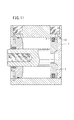
この流体圧シリンダ10は、図1に示されるように、圧力流体(例えば、圧縮エア)が供給・排出される第1ポート(第1の圧力流体出入ポート)16及び第2ポート(第2の圧力流体出入ポート)18を有するシリンダチューブ(シリンダ本体)12と、前記シリンダチューブ12の一方の開口部(開口端部)を閉塞するプレート状(平板状)のキャップ20と、前記シリンダチューブ12の他方の開口部(開口端部)を閉塞するロッドエンド30と、前記シリンダチューブ12の内部に軸線方向に沿って変位自在に設けられるピストン40と、前記ピストン40の端部に連結されるピストンロッド50と、からなる。
As shown in FIG. 1, the
シリンダチューブ12はアルミニウム等の金属製材料から円筒状に形成され、その一端部側(矢印A方向)の外周面に第1ポート16が形成されると共に、前記第1ポート16より所定間隔離間して他端部側(矢印B方向)の外周面に第2ポート18が形成されている。そして、前記第1ポート16及び第2ポート18は、それぞれ第1連通路19a及び第2連通路19bを介してシリンダチューブ12の内部に形成されるシリンダ室13と連通している。
The
キャップ20は、図2に示されるように、例えば、アルミニウム等の金属製材料からなるプレート体60をプレス成形することによって形成され、円盤状の本体部22と、該本体部22の外周が所定角度だけ軸線に向かって屈曲し、且つ半径外方向に拡径した外縁部24と、からなる。そして、図3に示されるように、キャップ20は、その外縁部24が、シリンダチューブ12の一方の開口部(矢印A方向)、すなわちロッドエンド30とは反対側に向かうように配設される。
As shown in FIG. 2, the
また、前記キャップ20は、外縁部24の外周径D2が、シリンダ室13の内周径D1に対して若干だけ大きく設定される。すなわち、キャップ20がシリンダチューブ12の一方の開口部に装着される際、該キャップ20の外縁部24が一方の開口部の内周壁15に対して食い込むように装着されることとなる。詳細には、外縁部24を構成する外周側の先端26が、シリンダチューブ12の内周壁15に対して所定深さだけ食い込み、該キャップ20が前記一方の開口部の内部に固定される。
The
また、前記キャップ20は、例えば、シリンダチューブ12と同様に金属製材料から形成され、しかも、該キャップ20の硬度E1は、前記シリンダチューブ12の硬度E2に対して大きくなるように設定されている(E1>E2)。
The
さらに、キャップ20には、例えば、アルマイト処理等の表面処理が施されている。この表面処理により形成される処理層の厚さは、例えば、約5〜30μmとなるように設定される。なお、キャップ20に対して施される表面処理は、上述したアルマイト処理に限定されるものではなく、例えば、クロメート処理や塗装等が施されてもよい。
Furthermore, the
ロッドエンド30は、図1に示されるように、小径部31と、該小径部31に隣接した大径部32とを有し、前記小径部31がシリンダチューブ12におけるキャップ20側(矢印A方向)となるように配置される。そして、該シリンダ室13の内周壁15に形成された第1環状溝14に対し止め輪33が装着されることにより、該止め輪33が前記大径部32の端面に当接し、前記ロッドエンド30がシリンダ室13内に位置決めされた状態で固定される。
As shown in FIG. 1, the
ロッドエンド30の中央部には、軸線方向(矢印A、B方向)に沿って貫通したロッド孔34が形成され、前記ロッド孔34にはピストンロッド50が挿通される。このロッド孔34から拡径して、第2環状溝35が形成され、この第2環状溝35にロッドパッキン36が装着される。前記ロッドパッキン36が、ピストンロッド50の外周面に当接することによって、シリンダ室13の内部の気密が保持される。また、ロッドエンド30の大径部32の外周面には、第3環状溝37を介してOリング38が装着される。
A
ピストン40は、前記シリンダチューブ12の内部に軸線方向に沿って変位自在に設けられる。前記ピストン40の外周面には、第4環状溝42を介してピストンパッキン43が装着され、該ピストンパッキン43によってシリンダ室13はキャップ側シリンダ室13aと、ロッドエンド側シリンダ室13bとに分割されている。
The
また、ピストン40の内部には、軸線方向(矢印A、B方向)に沿って貫通したピストン孔44が形成され、前記ピストン孔44にはピストンロッド50の連結部52が挿通される。このピストン孔44は、キャップ20側(矢印A方向)に向かってテーパー状に拡径して開口したキャップ側ピストン孔44aと、該キャップ側ピストン孔44aに連通してロッドエンド30側(矢印B方向)に同径で開口したロッドエンド側ピストン孔44bと、を有する。前記ピストンロッド50の連結部52は、前記ロッドエンド側ピストン孔44bに挿通された後、キャップ側ピストン孔44aを閉塞するように塑性変形されて、シリンダ本体12の軸線方向に直交する平面状に形成される。このため、ピストン40のキャップ20に臨む端面は、シリンダ本体12の軸線方向に直交する平面状に形成される。
Further, a
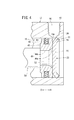
本実施の形態によれば、キャップ20に臨むピストン40の端面が前記キャップ20の本体部22に当接すると、キャップ20の外縁部24と、シリンダ室13の内周壁15と、前記ピストン40の端面によって囲まれた小さな空間(エア通路)S1、すなわち、シリンダ室13内に圧力流体を導入可能な小さな空間(エア通路)S1が形成される。
According to the present embodiment, when the end surface of the
前記空間S1は、第1連通路19aを通じて第1ポート16に連通している。
The space S1 communicates with the
また、前記空間S1は、図1に示されるとおり断面三角形状で環状に形成されているため、ピストン40がシリンダ室13内を周方向に回転した場合であっても、前記空間S1と、第1ポート16とは常に連通する。したがって、ピストン40の端面に圧力流体を確実に供給して加圧力を付与することができ好適である。
Further, since the space S1 is formed in an annular shape with a triangular cross section as shown in FIG. 1, even if the
さらにまた、前記第1連通路19aは、シリンダチューブ12の外周に設けられた第1ポート16の開口部よりも狭径に形成され、該第1連通路19aの開口部(先端)の全てが前記空間S1に臨むように設けられる。すなわち、第1連通路19aの開口部(先端)の直径は、シリンダ室13の内周壁15のうち、断面三角形状に設けられた前記空間S1を形成する一辺よりも短く形成される。このため、ピストン40の端面に圧力流体を確実に供給してピストン40の往復動作を行なうことができる。
Furthermore, the
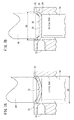
本発明の実施の形態に係る流体圧シリンダ10は、基本的に以上のように構成されるものであって、次に、前記キャップ20をシリンダチューブ(シリンダ本体)12に対して組み付ける工程について、図7A及び図7Bを参照しながら説明する。
The
先ず、シリンダチューブ12内部のシリンダ室13に、ピストン40及びピストンロッド50が挿通されていない状態で、該シリンダチューブ12の一方の開口部が上方となるようにシリンダチューブ12を位置決めして準備状態とする。
First, in a state where the
この準備状態において、シリンダチューブ12の他方の開口部(下方)からシリンダ室13に対して第1ポンチ(成形用治具)70が挿通され、該第1ポンチ70の端部は前記シリンダ室13におけるキャップ20の装着位置となるように配置される。この第1ポンチ70は、端部が平面状に形成された軸体からなり、その直径がシリンダ室13の内周径D1に対して若干だけ小さく設定される。この際、第1ポンチ70とシリンダ室13とが同軸上に設けられ、且つ、該第1ポンチ70の端面が、前記シリンダ室13の軸線と略直交するように配置されている。
In this preparatory state, a first punch (molding jig) 70 is inserted into the
次に、シリンダ室13の一方の開口部側、すなわち、上方側からキャップ20のベースとなるプレート体60が挿入される。このプレート体60は、略一定の厚さからなる断面湾曲形状に形成されると共に、前記プレート体60の外周径は、シリンダ室13の内周径D1に対して略同径又は若干だけ小さくなるように形成される。
Next, the
換言すれば、プレート体60の断面積が、シリンダ室13の断面積に対して少なくとも略同等以下に設定される。
In other words, the cross-sectional area of the
そして、プレート体60は、その膨出した中央部が下方となるように前記シリンダ室13へと挿入されて、前記プレート体60は第1ポンチ70の端面に載置された状態となる。プレート体60の外周径はシリンダ室13の内周径D1と略同じか若干小さく形成されているため、前記プレート体60は、シリンダ室13の内周壁15に接することなく前記シリンダ室13内に挿入される。したがって、該内周壁15が、プレート体60によって傷つけられることが回避される。
Then, the
最後に、シリンダ室13の一方の開口部側、すなわち、上方側から先端部がテーパー形状81に形成された第2ポンチ(成形用治具)80が挿入され、所定圧力で下降させられる。この第2ポンチ80は、第1ポンチ70と同様に、その下端面が平面状に形成された軸体からなると共に、その直径は、第1ポンチ70の直径より小さく設定されている。
Finally, a second punch (molding jig) 80 whose tip is formed in a tapered
そして、第2ポンチ80の下降によってプレート体60が該第2ポンチ80の端面と第1ポンチ70の端面との間で挟持されて押圧される。この押圧力によって、図7Bに示されるように、第1ポンチ70と第2ポンチ80との間に平面状の本体部22が形成されると共に、プレート体60の外周部分が、テーパー形状81の作用下に上方に向かって折曲されてキャップ20の外縁部24となる。換言すれば、第1ポンチ70及び第2ポンチ80によって挟持された部位が平面状の本体部22となり、また、該本体部22の外周部分であって、半径外方向に拡径し上方へと塑性変形した部位が外縁部24となって、前記プレート体60がキャップ20となる。
As the
このとき、前記外縁部24が、半径外方向に拡径し上方へと塑性変形することにより、前記キャップ20の外縁部24の外周径D2は、シリンダ室13の内周径D1よりも大きくなる(D2>D1)。このため、外縁部24の先端26はシリンダ室13の内周壁15に対して食い込んで係止することとなり、前記キャップ20は、シリンダチューブ12に対して固定される。
At this time, the
キャップ20が、シリンダチューブ(シリンダ本体)12に対して上記のように組み付けられることにより、ピストン40の端面が前記キャップ20の本体部22に当接すると、キャップ20の外縁部24と、シリンダ室13の内周壁15と、前記ピストン40の端面によって、シリンダ室13内に圧力流体を導入可能な空間(エア通路)S1が形成される(図1参照)。すなわち、段付き加工を行なうことなく、シリンダ室13内に圧力流体を導入可能な小さな空間(エア通路)S1を形成することができる。このため、段部の幅寸法が存在しないことからピストン40又はキャップ20の軸線方向の長さを短縮することができ、流体圧シリンダ10の全長を短くすることができる。
When the
しかも、段付き加工を不要とするため、製造工数を削減することができ、これに伴って製造効率の向上、製造コストの削減を図ることができる。 Moreover, since stepped machining is not required, the number of manufacturing steps can be reduced, and accordingly, the manufacturing efficiency can be improved and the manufacturing cost can be reduced.
また、キャップ20を構成する外縁部24をシリンダ室13の開口端部に向かって屈曲させ、該外縁部24の先端26を前記シリンダ室13の内周壁15に係止させる構成としたので、ピストン40の衝突によってキャップ20が押圧されると、前記外縁部24の先端26が押圧力によって前記シリンダ室13の内周壁15にさらに食い込むこととなる。このため、キャップ20はピストン40の衝撃を好適に吸収することができる。したがって、従来技術と比べて、強度確保に必要なキャップ20の肉厚を、軸線方向に対して薄くすることができ、その結果、ストロークを小さくすることなく流体圧シリンダ10の全長を短くすることができる。
Further, the
さらにまた、前記プレート体60は、その外周径がシリンダ室13の内周径D1に対して若干だけ小さくなるように形成されるため、前記シリンダ室13の内周壁15に対して摺動することなくシリンダ室13に挿入される。このため、プレート体60挿入時に、該内周壁15がプレート体60によって傷つけられることがなく、該傷を通じた圧力流体の僅かな漏れが生じることはなく好適である。
Furthermore, the
さらに、キャップ20は、シリンダ室13の軸線方向に沿った所望の位置に固定可能であるため、従来技術に係る流体圧シリンダ等で用いられていたキャップを固定するため係止リング、該係止リングが装着される溝部、及びキャップの外周面に設けられるOリングを不要とすることができる。そのため、流体圧シリンダ10の製造コスト及び部品点数を削減できると共に、製造効率を向上させることができる。
Further, since the
さらに、キャップ20は、その外縁部24がシリンダ室13とは反対側に向かうように配置されているため、前記キャップ20に対してピストン40の押圧力が付与された場合や、前記シリンダ室13内の圧力流体の圧力が付与され、前記シリンダ室13から離間する方向に押圧された場合でも、前記外縁部24の先端26が前記押圧力によってさらにシリンダ室13の内周壁15へと食い込む。このため、前記キャップ20がシリンダチューブ12に対して脱落することが確実に阻止される。すなわち、外縁部24は、キャップ20の脱落を防止するための抜け止め機能を営む。
Further, the
またさらに、キャップ20に対して表面処理を行っているため、該表面処理、塗装等によってシリンダチューブ12におけるシリンダ室13の内周壁15に対して前記キャップ20を密着させることができる。その結果、キャップ20とシリンダチューブ12のシリンダ室13との間を通じた圧力流体の微小な漏れを確実に阻止することができる。
Furthermore, since the
また、キャップ20は、シリンダチューブ12と同一の材質で形成されるため、熱膨張率が同一となり、温度変化による体積膨張率が同一となる。そのため、流体圧シリンダ10に温度変化が生じた場合でも、シリンダチューブ12とキャップ20との間に隙間が生じることがない。その結果、温度変化に起因した圧力流体の漏れを確実に防止することができる。さらに、キャップ20とシリンダチューブ12とを凝着させることができるため、該キャップ20とシリンダチューブ12のとの間を通じた圧力流体の微小な漏れも確実に阻止することができる。
Moreover, since the
さらに、キャップ20の硬度E1が、シリンダチューブ12の硬度E2に対して大きくなるように形成されているため(E1>E2)、前記キャップ20をシリンダ室13の内周壁15に対して食い込ませるように装着することができる。その結果、キャップ20が、シリンダチューブ12に対してより確実且つ強固に固定されることとなる。
Further, since the hardness E1 of the
また、シリンダチューブ12及びキャップ20は、いずれもアルミニウムから形成されているため、前記シリンダチューブ12に対して前記キャップ20を装着した後に、アルマイト処理等の表面処理を一体的に行うことが可能となる。その結果、キャップ20とシリンダチューブ12との間にも表面処理を行う際の処理剤が浸入し、わずかな隙間も塞がれることとなり、圧力流体の微小な漏れが防止されると共に、製造工数の削減を図ることができる。
Further, since both the
さらに、キャップ20を、プレート状の金属製材料から形成しているため、該キャップ20に対してピストン40を当接させ停止させる場合にも、当接時に該キャップ20が弾性変形するため、前記ピストン40から付与される衝撃を緩衝することができる。
Furthermore, since the
本発明の実施の形態に係る流体圧シリンダ10は、基本的に以上のように構成される。次にその動作について説明する。
The
図4に示されるように、ピストン40がキャップ20に当接し、両者がそれぞれの端面に塗布されたグリス(図示せず)によって密着した状態を、初期位置として説明する。
As shown in FIG. 4, the state where the
先ず、この初期位置において、図示しない圧力流体供給源から第1ポート16へ、圧力流体が導入される。この場合、第2ポート18は、図示しない切換弁の操作下に大気開放状態としておく。
First, in this initial position, the pressure fluid is introduced from the pressure fluid supply source (not shown) to the
この第1ポート16に供給された圧力流体は、第1連通路19aを通じてシリンダ室13内に導入される。より詳細には、当該圧力流体は、キャップ20の外縁部24と、シリンダ室13の内周壁15と、前記ピストン40の端面によって形成された空間(エア通路)S1内に導入される。
The pressure fluid supplied to the
次に、図5に示されるように、前記空間(エア通路)S1に導入された圧力流体は、ピストン40の端面をロッドエンド30側(矢印B方向)に向かって押圧する。これにより、キャップ20の本体部22とグリスによって密着していたピストン40が、キャップ20から離間する方向、すなわちロッドエンド30側(矢印B方向)へと変位する。
Next, as shown in FIG. 5, the pressure fluid introduced into the space (air passage) S <b> 1 presses the end surface of the
ピストン40がキャップ20の本体部22と離間すると、圧力流体は、さらにピストン40の端面を押圧する。
When the
これにより、図6に示されるように、ピストン40は、ピストンロッド50と共にキャップ20から離間する方向(矢印B方向)へとさらに変位する。このため、ピストンロッド50はロッドエンド30に対して徐々に外部へ突出していき、ロッドエンド30に臨むピストン40の端面がロッドエンド30の端面に当接することにより変位終端位置となる。
Thereby, as shown in FIG. 6, the
次に、ピストン40を上述した変位終端位置から再び初期位置へと復帰させる場合には、第1ポート16に供給されていた圧力流体を、図示しない切換装置を介して第2ポート18へと供給する。ピストン40は、第2連通路19bを通じてシリンダ室13へと供給された圧力流体によって、ロッドエンド30から離間する方向(矢印A方向)に向かって徐々に押圧される。この場合、第1ポート16は大気開放状態にある。
Next, when returning the
そして、ピストン40の変位と共にピストンロッド50が徐々にロッドエンド30の内部に収容されるように変位し、前記ピストン40がキャップ20に当接し、圧力流体の供給が停止されることで初期位置へ復帰する。
Then, with the displacement of the
なお、キャップ20を形成するプレート体60は、上述したように断面湾曲形状に形成される場合に限定されるものではない。例えば、図8Aに示されるように、予め外周部が上方に向かって折曲された外縁部124を有したプレート体160に対し、前記プレート体160の断面形状に対応した第3ポンチ180を用いて、キャップ120が成形されるようにしてもよい(図8B参照)。
In addition, the
この場合、プレート体160に予め本体部122と外縁部124が形成されているため、キャップ120における外縁部124をより一層確実且つ高精度に形成することが可能となる。また、シリンダ室13の内部にキャップ120が装着された際、外縁部124の先端126が前記シリンダ室13の内周壁15に対して確実に食い込むため、該キャップ120がシリンダチューブ12に対して確実且つ強固に係止されることが可能となる。
In this case, since the
また、上述したキャップ20及びキャップ120の代わりに、図9A及び図9Bに示される断面湾曲状の本体部222と、該本体部222の外周に平面状に形成された外縁部224とを有したキャップ220を用いるようにしてもよい。
Further, instead of the
図9A及び図9Bに示されるキャップ220では、第1ポンチ70及び第2ポンチ80によるプレス成形によって本体部222が平面状に塑性変形し、それに伴って、該本体部222は外縁部224と共に半径外方向に塑性流動する。この結果、キャップ220が、全体的に平面状に形成され、その外周径が拡径することとなる。これにより、キャップ220は、その外縁部224がシリンダ室13の内周壁15に対して直交するように食い込んで係止される。
In the
さらにまた、上述したピストン40の代わりに、図10に示すように、軸線方向(矢印A、B方向)に沿って略一定径で貫通するピストン孔144が形成されたピストン140を用いるようにしてもよい。
Furthermore, instead of the above-described
ピストン孔144には、ピストンロッド50の一端に連結された連結体150が挿入される。該連結体150は、例えば、ステンレス鋼等の金属製材料からなる板材をプレス成形することによって形成され、円盤状の本体部153と、該本体部153の外周が所定角度だけ軸線に向かって屈曲し、且つ半径外方向に拡径した外縁部154と、からなる。該連結体150は、その外縁部154が、シリンダチューブ12の一方の開口部(矢印A方向)、すなわちキャップ20側に向かうように配設される。
A connecting
外縁部154の外周径は、ピストン孔144の内周径に対して若干だけ大きく設定される。すなわち、該連結体150の外縁部154がピストン孔144の内周壁に対して食い込むように装着されることとなる。詳細には、外縁部154を構成する外周側の先端156が、ピストン孔144の内周壁に対して所定深さだけ食い込み、該連結体150がピストン孔144内部に固定される。
The outer peripheral diameter of the
ピストン140が変位しキャップ20に当接すると、連結体150が弾性変形し、キャップ20に付与される衝撃が緩衝される。したがって、ピストン40を用いた場合と比較して、強度確保に必要なキャップ20の肉厚を、軸線方向に対してさらに薄くすることができ好適である。
When the
なお、本発明に係る流体圧シリンダに用いられるキャップ及びその固定方法は、上述の実施の形態に限らず、本発明の要旨を逸脱することなく、種々の構成を採り得ることはもちろんである。 In addition, the cap used for the fluid pressure cylinder according to the present invention and the fixing method thereof are not limited to the above-described embodiments, and it goes without saying that various configurations can be adopted without departing from the gist of the present invention.
10…流体圧シリンダ
12…シリンダチューブ(シリンダ本体)
13…シリンダ室
15…内周壁
16…第1ポート
18…第2ポート
19a…第1連通路
19b…第2連通路
20、120、220…キャップ
22、222…本体部
24、124、224…外縁部
26、126…先端
30…ロッドエンド
40、140…ピストン
50…ピストンロッド
60、160…プレート体
70…第1ポンチ(成形用治具)
80…第2ポンチ(成形用治具)
150…連結体
180…第3ポンチ
D1…シリンダ室の内周径
D2…外縁部の外周径
S1…空間(エア通路)
10 ...
DESCRIPTION OF
80 ... second punch (molding jig)
150 ...
Claims (3)
前記シリンダ本体の軸線方向に沿って前記シリンダ室内を変位し、ピストンロッドが連結されるピストンと、
前記シリンダ本体に設けられた前記シリンダ室の一方の開口端部を閉塞するためのキャップと、
前記シリンダ室の他方の開口端部を閉塞するロッドエンドと、を備え、
前記シリンダ室の一方の開口端部近傍において、前記シリンダ本体に該シリンダ室に連通する第1の圧力流体出入ポートを設け、
前記シリンダ室の他方の開口端部近傍において、前記シリンダ本体に該シリンダ室に連通する第2の圧力流体出入ポートを設け、
前記キャップは、
前記ピストンの端面が当接する平板状の本体部と、
前記本体部の外周に設けられ、前記本体部から前記シリンダ室の一方の開口端部に向かって屈曲してその先端が前記シリンダ室の内周壁に係止される外縁部と、を有し、
前記ピストンの端面が前記本体部に当接するときに、
前記外縁部と、
前記シリンダ室の内周壁と、
前記ピストンの端面と、
によって囲まれ、且つ前記第1の圧力流体出入ポートに連通する空間を形成すると共に、
前記空間は、断面三角形状で環状に形成されることを特徴とする流体圧シリンダ。 A cylinder body having a cylinder chamber into which pressure fluid is introduced;
A piston that is displaced in the cylinder chamber along the axial direction of the cylinder body, and to which a piston rod is coupled;
A cap for closing one open end of the cylinder chamber provided in the cylinder body;
A rod end that closes the other open end of the cylinder chamber,
In the vicinity of one opening end of the cylinder chamber, the cylinder body is provided with a first pressure fluid inlet / outlet port communicating with the cylinder chamber,
In the vicinity of the other opening end of the cylinder chamber, the cylinder body is provided with a second pressure fluid inlet / outlet port communicating with the cylinder chamber,
The cap is
A flat plate-like main body with which the end face of the piston abuts,
An outer edge portion provided on an outer periphery of the main body portion, bent from the main body portion toward one opening end portion of the cylinder chamber, and a tip end of which is locked to an inner peripheral wall of the cylinder chamber;
When the end surface of the piston contacts the main body,
The outer edge;
An inner peripheral wall of the cylinder chamber;
An end face of the piston;
And forming a space communicating with the first pressure fluid inlet / outlet port ,
The fluid pressure cylinder is characterized in that the space is formed in an annular shape with a triangular cross section .
前記ピストンは、前記キャップに臨む端面が前記シリンダ本体の軸線方向に直交する平面状に設けられていることを特徴とする流体圧シリンダ。 The fluid pressure cylinder according to claim 1, wherein
The fluid pressure cylinder according to claim 1, wherein the piston has an end surface facing the cap provided in a planar shape perpendicular to the axial direction of the cylinder body.
前記第1の圧力流体出入ポートの狭径な先端全てが、断面三角形状で環状に形成される前記空間に臨むことを特徴とする流体圧シリンダ。 The fluid pressure cylinder according to claim 1 or 2 ,
A fluid pressure cylinder characterized in that all of the narrow-diameter ends of the first pressure fluid inlet / outlet ports face the space formed in an annular shape having a triangular cross section.
Priority Applications (6)
| Application Number | Priority Date | Filing Date | Title |
|---|---|---|---|
| JP2012136776A JP6028994B2 (en) | 2012-06-18 | 2012-06-18 | Fluid pressure cylinder |
| US13/900,689 US9746006B2 (en) | 2012-06-18 | 2013-05-23 | Fluid pressure cylinder |
| KR1020130064041A KR102052979B1 (en) | 2012-06-18 | 2013-06-04 | Fluid pressure cylinder |
| TW102120864A TWI577893B (en) | 2012-06-18 | 2013-06-13 | Fluid pressure cylinder |
| DE102013106233A DE102013106233A1 (en) | 2012-06-18 | 2013-06-14 | Fluid pressure cylinder |
| CN201310240072.9A CN103511384B (en) | 2012-06-18 | 2013-06-17 | Fluid pressure cylinder |
Applications Claiming Priority (1)
| Application Number | Priority Date | Filing Date | Title |
|---|---|---|---|
| JP2012136776A JP6028994B2 (en) | 2012-06-18 | 2012-06-18 | Fluid pressure cylinder |
Publications (3)
| Publication Number | Publication Date |
|---|---|
| JP2014001779A JP2014001779A (en) | 2014-01-09 |
| JP2014001779A5 JP2014001779A5 (en) | 2015-06-18 |
| JP6028994B2 true JP6028994B2 (en) | 2016-11-24 |
Family
ID=49668164
Family Applications (1)
| Application Number | Title | Priority Date | Filing Date |
|---|---|---|---|
| JP2012136776A Active JP6028994B2 (en) | 2012-06-18 | 2012-06-18 | Fluid pressure cylinder |
Country Status (6)
| Country | Link |
|---|---|
| US (1) | US9746006B2 (en) |
| JP (1) | JP6028994B2 (en) |
| KR (1) | KR102052979B1 (en) |
| CN (1) | CN103511384B (en) |
| DE (1) | DE102013106233A1 (en) |
| TW (1) | TWI577893B (en) |
Families Citing this family (7)
| Publication number | Priority date | Publication date | Assignee | Title |
|---|---|---|---|---|
| JP6159938B2 (en) * | 2014-04-14 | 2017-07-12 | Smc株式会社 | Fluid pressure cylinder |
| JP6403071B2 (en) * | 2015-06-11 | 2018-10-10 | Smc株式会社 | Fluid pressure cylinder |
| JP6403073B2 (en) * | 2015-06-11 | 2018-10-10 | Smc株式会社 | Fluid pressure cylinder |
| JP6558583B2 (en) * | 2016-08-10 | 2019-08-14 | Smc株式会社 | Fluid pressure device and method of manufacturing piston assembly |
| JP6598079B2 (en) * | 2016-12-06 | 2019-10-30 | Smc株式会社 | Rod assembly and fluid pressure device |
| JP6903844B2 (en) * | 2018-09-12 | 2021-07-14 | Smc株式会社 | Fluid pressure cylinder |
| CN110630582B (en) * | 2019-09-10 | 2022-09-06 | 长沙理工大学 | Cylinder energy storage type hydraulic cylinder |
Family Cites Families (12)
| Publication number | Priority date | Publication date | Assignee | Title |
|---|---|---|---|---|
| US414460A (en) * | 1889-11-05 | Steam-engine | ||
| US1360043A (en) * | 1919-04-16 | 1920-11-23 | Vsevolod N Stankoff | Inside cylinder-covering for reducing steam consumption |
| US1801006A (en) * | 1927-12-03 | 1931-04-14 | La Mont Corp | Sealing closure and method of applying same |
| US2952400A (en) * | 1955-01-15 | 1960-09-13 | Hintze Rudolf | Motor-compressor |
| US3120338A (en) * | 1962-09-17 | 1964-02-04 | Walker Mfg Co | Compressor |
| US3786730A (en) * | 1972-06-07 | 1974-01-22 | Pyroil Co Inc | Tire pump |
| US4924758A (en) * | 1988-08-01 | 1990-05-15 | Yuda Lawrence F | Compact fluid operated apparatus and method |
| SE470386B (en) * | 1992-06-26 | 1994-02-07 | Mecman Ab Rexroth | Pressure fluid cylinder |
| DE60133147T2 (en) * | 2000-03-01 | 2009-02-19 | Smc K.K. | cylinder |
| JP3941064B2 (en) | 2004-02-27 | 2007-07-04 | Smc株式会社 | Fluid pressure cylinder and manufacturing method thereof |
| JP5118708B2 (en) * | 2007-11-06 | 2013-01-16 | 株式会社コガネイ | Fluid pressure cylinder |
| JP5636612B2 (en) * | 2010-04-01 | 2014-12-10 | Smc株式会社 | Cap used for fluid pressure device and fixing method thereof |
-
2012
- 2012-06-18 JP JP2012136776A patent/JP6028994B2/en active Active
-
2013
- 2013-05-23 US US13/900,689 patent/US9746006B2/en active Active
- 2013-06-04 KR KR1020130064041A patent/KR102052979B1/en active IP Right Grant
- 2013-06-13 TW TW102120864A patent/TWI577893B/en active
- 2013-06-14 DE DE102013106233A patent/DE102013106233A1/en active Pending
- 2013-06-17 CN CN201310240072.9A patent/CN103511384B/en active Active
Also Published As
| Publication number | Publication date |
|---|---|
| US20130336827A1 (en) | 2013-12-19 |
| CN103511384B (en) | 2018-04-06 |
| KR102052979B1 (en) | 2019-12-06 |
| TW201408892A (en) | 2014-03-01 |
| KR20130142070A (en) | 2013-12-27 |
| DE102013106233A1 (en) | 2013-12-19 |
| US9746006B2 (en) | 2017-08-29 |
| TWI577893B (en) | 2017-04-11 |
| JP2014001779A (en) | 2014-01-09 |
| CN103511384A (en) | 2014-01-15 |
Similar Documents
| Publication | Publication Date | Title |
|---|---|---|
| JP6028994B2 (en) | Fluid pressure cylinder | |
| JP6103384B2 (en) | Piston connection structure used in fluid pressure cylinder and connection method thereof | |
| TWI583879B (en) | Fluid pressure cylinder | |
| JP6829869B2 (en) | Oil jet device | |
| JP5464408B2 (en) | Fluid pressure cylinder | |
| JP5636612B2 (en) | Cap used for fluid pressure device and fixing method thereof | |
| TW201702491A (en) | Fluid pressure cylinder | |
| JP2008275164A (en) | Seal assembly and wet type twin clutch assembly with seal assembly | |
| US10989325B2 (en) | Method for producing an actuator | |
| TW201713863A (en) | Fluid pressure device and method for producing the same | |
| KR102079672B1 (en) | Hydraulic cylinder | |
| KR102015495B1 (en) | Hydraulic cylinder | |
| JP2016117122A (en) | Locating and clamping device, and locating and clamping method | |
| TWI650491B (en) | Fluid pressure cylinder | |
| JP6518762B2 (en) | Fluid pressure clamp device | |
| TWI605200B (en) | Fluid pressure cylinder | |
| JP2005240936A (en) | Fluid-pressure cylinder and its manufacturing method | |
| KR102148655B1 (en) | Piston for a piston pump of a vehicle braking system | |
| JP2018155406A (en) | Cylinder device, press device, work joining device, work fixing device, cylinder device operation method, work pressing method, work joining method, and work fixing method | |
| JP2003185019A (en) | Seal device of pressure vessel |
Legal Events
| Date | Code | Title | Description |
|---|---|---|---|
| A521 | Request for written amendment filed |
Free format text: JAPANESE INTERMEDIATE CODE: A523 Effective date: 20150421 |
|
| A621 | Written request for application examination |
Free format text: JAPANESE INTERMEDIATE CODE: A621 Effective date: 20150421 |
|
| A977 | Report on retrieval |
Free format text: JAPANESE INTERMEDIATE CODE: A971007 Effective date: 20160205 |
|
| A131 | Notification of reasons for refusal |
Free format text: JAPANESE INTERMEDIATE CODE: A131 Effective date: 20160216 |
|
| A521 | Request for written amendment filed |
Free format text: JAPANESE INTERMEDIATE CODE: A523 Effective date: 20160401 |
|
| TRDD | Decision of grant or rejection written | ||
| A01 | Written decision to grant a patent or to grant a registration (utility model) |
Free format text: JAPANESE INTERMEDIATE CODE: A01 Effective date: 20160906 |
|
| A61 | First payment of annual fees (during grant procedure) |
Free format text: JAPANESE INTERMEDIATE CODE: A61 Effective date: 20161006 |
|
| R150 | Certificate of patent or registration of utility model |
Ref document number: 6028994 Country of ref document: JP Free format text: JAPANESE INTERMEDIATE CODE: R150 |
|
| R250 | Receipt of annual fees |
Free format text: JAPANESE INTERMEDIATE CODE: R250 |
|
| R250 | Receipt of annual fees |
Free format text: JAPANESE INTERMEDIATE CODE: R250 |
|
| R250 | Receipt of annual fees |
Free format text: JAPANESE INTERMEDIATE CODE: R250 |
|
| R250 | Receipt of annual fees |
Free format text: JAPANESE INTERMEDIATE CODE: R250 |
|
| R250 | Receipt of annual fees |
Free format text: JAPANESE INTERMEDIATE CODE: R250 |