EP3553261A1 - Closing element moving device and door comprising these - Google Patents
Closing element moving device and door comprising these Download PDFInfo
- Publication number
- EP3553261A1 EP3553261A1 EP18166790.8A EP18166790A EP3553261A1 EP 3553261 A1 EP3553261 A1 EP 3553261A1 EP 18166790 A EP18166790 A EP 18166790A EP 3553261 A1 EP3553261 A1 EP 3553261A1
- Authority
- EP
- European Patent Office
- Prior art keywords
- container
- size
- closure member
- storage volume
- closing element
- Prior art date
- Legal status (The legal status is an assumption and is not a legal conclusion. Google has not performed a legal analysis and makes no representation as to the accuracy of the status listed.)
- Granted
Links
- 239000012530 fluid Substances 0.000 claims abstract description 108
- 239000011888 foil Substances 0.000 claims description 20
- 230000002093 peripheral effect Effects 0.000 claims description 10
- 230000001419 dependent effect Effects 0.000 claims description 2
- 239000002985 plastic film Substances 0.000 description 6
- 238000007599 discharging Methods 0.000 description 5
- 239000011324 bead Substances 0.000 description 4
- 230000006835 compression Effects 0.000 description 4
- 238000007906 compression Methods 0.000 description 4
- 229920006255 plastic film Polymers 0.000 description 4
- 241000446313 Lamella Species 0.000 description 3
- 239000010720 hydraulic oil Substances 0.000 description 3
- XLYOFNOQVPJJNP-UHFFFAOYSA-N water Substances O XLYOFNOQVPJJNP-UHFFFAOYSA-N 0.000 description 3
- IJGRMHOSHXDMSA-UHFFFAOYSA-N Atomic nitrogen Chemical compound N#N IJGRMHOSHXDMSA-UHFFFAOYSA-N 0.000 description 2
- 229910000831 Steel Inorganic materials 0.000 description 2
- 230000008878 coupling Effects 0.000 description 2
- 238000010168 coupling process Methods 0.000 description 2
- 238000005859 coupling reaction Methods 0.000 description 2
- 239000007788 liquid Substances 0.000 description 2
- 239000000463 material Substances 0.000 description 2
- 229910052751 metal Inorganic materials 0.000 description 2
- 239000002184 metal Substances 0.000 description 2
- 239000010959 steel Substances 0.000 description 2
- 239000000654 additive Substances 0.000 description 1
- 239000003570 air Substances 0.000 description 1
- 229910052782 aluminium Inorganic materials 0.000 description 1
- XAGFODPZIPBFFR-UHFFFAOYSA-N aluminium Chemical compound [Al] XAGFODPZIPBFFR-UHFFFAOYSA-N 0.000 description 1
- 239000002131 composite material Substances 0.000 description 1
- 238000010276 construction Methods 0.000 description 1
- 230000007423 decrease Effects 0.000 description 1
- 230000000881 depressing effect Effects 0.000 description 1
- 239000012799 electrically-conductive coating Substances 0.000 description 1
- 239000004744 fabric Substances 0.000 description 1
- 239000007789 gas Substances 0.000 description 1
- 239000011261 inert gas Substances 0.000 description 1
- 230000007774 longterm Effects 0.000 description 1
- 238000004519 manufacturing process Methods 0.000 description 1
- 239000000203 mixture Substances 0.000 description 1
- 229910052757 nitrogen Inorganic materials 0.000 description 1
- 239000003921 oil Substances 0.000 description 1
- 238000011084 recovery Methods 0.000 description 1
- 230000006641 stabilisation Effects 0.000 description 1
- 238000011105 stabilization Methods 0.000 description 1
- 239000004753 textile Substances 0.000 description 1
- 230000037303 wrinkles Effects 0.000 description 1
Images


Classifications
-
- E—FIXED CONSTRUCTIONS
- E05—LOCKS; KEYS; WINDOW OR DOOR FITTINGS; SAFES
- E05B—LOCKS; ACCESSORIES THEREFOR; HANDCUFFS
- E05B51/00—Operating or controlling locks or other fastening devices by other non-mechanical means
- E05B51/02—Operating or controlling locks or other fastening devices by other non-mechanical means by pneumatic or hydraulic means
-
- E—FIXED CONSTRUCTIONS
- E05—LOCKS; KEYS; WINDOW OR DOOR FITTINGS; SAFES
- E05B—LOCKS; ACCESSORIES THEREFOR; HANDCUFFS
- E05B17/00—Accessories in connection with locks
- E05B17/20—Means independent of the locking mechanism for preventing unauthorised opening, e.g. for securing the bolt in the fastening position
- E05B17/2007—Securing, deadlocking or "dogging" the bolt in the fastening position
- E05B17/203—Securing, deadlocking or "dogging" the bolt in the fastening position not following the movement of the bolt
- E05B17/2034—Securing, deadlocking or "dogging" the bolt in the fastening position not following the movement of the bolt moving pivotally or rotatively
-
- E—FIXED CONSTRUCTIONS
- E05—LOCKS; KEYS; WINDOW OR DOOR FITTINGS; SAFES
- E05B—LOCKS; ACCESSORIES THEREFOR; HANDCUFFS
- E05B51/00—Operating or controlling locks or other fastening devices by other non-mechanical means
- E05B51/02—Operating or controlling locks or other fastening devices by other non-mechanical means by pneumatic or hydraulic means
- E05B2051/026—Operating or controlling locks or other fastening devices by other non-mechanical means by pneumatic or hydraulic means with manually generated fluid pressure
-
- E—FIXED CONSTRUCTIONS
- E05—LOCKS; KEYS; WINDOW OR DOOR FITTINGS; SAFES
- E05B—LOCKS; ACCESSORIES THEREFOR; HANDCUFFS
- E05B65/00—Locks or fastenings for special use
- E05B65/0075—Locks or fastenings for special use for safes, strongrooms, vaults, fire-resisting cabinets or the like
Definitions
- the invention relates to a closing element movement device and a door, which has these.
- Swing doors e.g. for safes, vaults, etc.
- appropriate closing elements e.g. Latches, bolts, strips, etc., lockable, in order to prevent access to rooms safely and permanently, so that only authorized persons have access to these rooms.
- closing elements e.g. Latches, bolts, strips, etc.
- the closing elements are actuated together by means of the bolt mechanism, for example after authentication by a key-lock system, a combination lock system, etc., in order to unlock the door and open the door leaf.
- a closing member moving device and a door with a closing member moving device which allow a cost-effective and space-saving arrangement.
- closure member mover and door are described in the respective dependent claims.
- a closure member mover may include a fluid system, an actuator, and a (eg, two, three, four, five, six, seven, eight, nine, ten, or more) closure members.
- the fluid system can be provided, for example, with a first (eg elastically or reversibly) deformable container, a second (eg elastically or reversibly) deformable container and a connecting line which fluidly connects the first container to the second container.
- the first container may form a storage volume that is variable between a first size and a second size (eg, the first size is a size at which, for example, at least substantially the maximum storage volume is provided in the first container and, for example, the second size is a size at which, for example, at least substantially no storage volume is provided in the first container).
- the first size is a size at which, for example, at least substantially the maximum storage volume is provided in the first container and, for example, the second size is a size at which, for example, at least substantially no storage volume is provided in the first container.
- the second container may form a working volume that is variable between a first size and a second size (eg, the first size is a size at which, for example, at least substantially no working volume is provided in the second container and, for example, the second size is a size at which, for example, at least substantially the maximum working volume is provided in the second container).
- a working fluid eg, a liquid such as oil, eg. Hydraulic oil, water, and mixtures thereof, for example, mixed with additives for long-term stabilization of the liquid, or a gas such as. Air, nitrogen, inert gases, etc.
- a working fluid eg, a liquid such as oil, eg. Hydraulic oil, water, and mixtures thereof, for example, mixed with additives for long-term stabilization of the liquid, or a gas such as. Air, nitrogen, inert gases, etc.
- the actuator e.g., a pivot lever, a rocker arm, a push button, etc.
- the actuator may e.g. movable (e.g., pivotable, tiltable, slidable, e.g., manually by a user) and may be e.g. selectively deforming (e.g., compressing and / or expanding) the first container to vary the storage volume of the first container between the first size and the second size.
- the closure member (e.g., a striker, a latch, a striker, a striker, etc.) may e.g. be movable (e.g., displaceable and / or pivotable) between a first position and a second position, and may e.g. be coupled with the second container (directly or indirectly).
- the storage volume of the first container is e.g. is varied (e.g., compressed or expanded) by the actuator between the first size and the second size, e.g. the working fluid is discharged from the storage volume or introduced into the storage volume.
- the working volume of the second container can be varied between the first size and the second size and the second container can be deformed (eg expanded or compressed) around the closure element to move between the first position and the second position.
- the first size of the storage volume (e.g., at least substantially) may be equal to the second size of the working volume.
- the closure member mover may further include a closure member biasing member (eg, a compression or extension spring) which biases the closure member to a biasing force to one of the first position and the second position.
- a closure member biasing member eg, a compression or extension spring
- the closure member mover may e.g. and a first container biasing member (eg, a tension spring disposed outside and coupled to the first container and / or a compression spring disposed within and coupled to the first container) for receiving the first container biasing the first size of the storage volume to, in a state in which the first container is not deformed by the actuating element, withdraw the working fluid from the second container and cause the working volume of the second container to assume its first size (eg the first container itself may be configured to include the first container biasing member integrally, for example, in the manner of an elastic container sleeve which, when there is no load on the container, automatically forms the first size of the storage volume).
- a first container biasing member eg, a tension spring disposed outside and coupled to the first container and / or a compression spring disposed within and coupled to the first container
- the fluid system of the closure member mover may be e.g. further comprising a third deformable container, a fourth deformable container, and a second connection line fluidly connecting the third container to the fourth container (eg, the first container, the second container, and the connecting conduit are the third container, the fourth container, and the second Connecting line formed separately).
- the third container may form a second storage volume that is variable between a first size and a second size (eg, the first size is one size, eg, at least substantially the maximum second storage volume in the third Container is provided, and for example, the second size is a size in which, for example, at least substantially no second storage volume is provided in the third container).
- the first size is one size, eg, at least substantially the maximum second storage volume in the third Container is provided
- the second size is a size in which, for example, at least substantially no second storage volume is provided in the third container.
- the fourth container may, for example, form a second working volume depending on a degree of deformation of the fourth container, that is variable between a first size and a second size (eg, the first size is a size at which, for example, at least substantially no second working volume is provided in the fourth container, and eg, the second size is a size at which, for example, at least Essentially the maximum second working volume is provided in the fourth container).
- a first size is a size at which, for example, at least substantially no second working volume is provided in the fourth container
- the second size is a size at which, for example, at least Essentially the maximum second working volume is provided in the fourth container.
- the third container may be deformable by the actuator to vary the second storage volume of the third container between the first size and the second size, and e.g. the closure element can also be coupled to the fourth container.
- the second storage volume of the third container is varied (e.g., compressed or expanded) by the actuator between the first size and the second size, e.g. the working fluid is discharged from the second storage volume of the third container or introduced into the second storage volume of the third container.
- the second working volume of the fourth container may be varied between the first size and the second size, and the fourth container may be deformed to move the closure member from the second position to move to the first position.
- the actuator may e.g. be set up so that selectively only the first container or the third container can be actuated by it.
- one, several or all of the containers may be formed in a lamella, meander or cushion shape.
- the fluid system may, for example, be between two overlapping, adjacent films (eg plastic films, film laminates, for example of a plastic film, an aluminum foil and / or a textile layer; for example, both films be the same, for example, consist of the same material, and / or have the same thickness / size, or may be different from each other) and may, for example, a contour of the container (eg an outer contour, for example.
- a contour of the container eg an outer contour, for example.
- the connecting line (s) may be formed by a connecting portion at which the two foils are joined together (eg, welded, glued, pressed / pressed, sewn, or combinations thereof).
- the connecting portion may be formed as a working fluid-tight seam or may be e.g. the connecting portion occupy at least the (eg area) area of the two foils, optionally occupy completely, in which none of the container and of the connecting line is formed (for example openings may be provided in the foils, which are also surrounded by the connecting portion and thus against the storage or working volume are fluid-tight).
- the seam can e.g. at least in sections (eg along a seam longitudinal direction) have a width of about 0.5 mm to about 6 mm, preferably of about 4 mm, or have a mesh structure in which separate mesh spaces are formed within the seam between the two films, in which the two films (eg composite film, high-strength plastic film, etc.) are not connected to each other (eg welded) (for example, the mesh spaces are separated by lattice-like regions of the connecting portion).
- the two films eg composite film, high-strength plastic film, etc.
- separate side rooms may be formed between the two foils Have volume that is smaller than that of the corresponding volume of the container (eg the storage volume or the working volume) and / or the connecting line, for example at least 10 times smaller.
- the side rooms can be optionally formed by the meshes of the seam, for example.
- a door e.g., a vault door, such as a vault cabinet or vault
- the door panel may be provided with a front surface (e.g., an armor plate, such as a steel plate), a rear surface, and a peripheral edge surrounding the door leaf.
- the closure member mover may e.g. be arranged on the rear side surface or in a cavity which is formed between the front side surface and the rear side surface.
- the closure member or members of the closure member mover may or may be e.g. projecting beyond the peripheral edge of the door panel in one of the first position and the second position.
- the door can e.g. further comprising a security container which overlaps between the front side surface of the door leaf and the closing element moving device and with the closing element moving device, e.g. optionally completely overlapping, may be arranged (for example, the security container may at least substantially the same size as the front side surface and be arranged congruent with this).
- the containment may include a containment fluid (e.g., a fluid as described for the working fluid of the closure member mover) that is under a predetermined pressure (e.g., overpressure, eg, against the outside of the door panel).
- the security container can eg between two overlapping, adjacent films (eg films, as they are for the fluid system of the closure element movement device are described) may be formed.
- the contour (eg outer contour, for example in a plane between the two foils) of the security container can be formed, for example, by a connecting section to which the two foils are connected to one another (for example, the connecting section of the containment can be in the manner of the connecting section of the fluid system) Closing element moving device to be executed).
- one of the two films of the containment can be one of the two films that form the fluid system of the closure element movement device (eg, the door then has three interconnected films, wherein between each two of the films the fluid system and the containment are formed)
- the two films forming the containment are separated from the two films forming the fluid system of the closure member mover by a plate (eg, steel plate) extending between the closure member mover and the containment (eg, the door (the door leaf) then two interconnected foils of the containment and two interconnected foils of the fluid system separated by the plate).
- a plate eg, steel plate
- the closing member of the closing member moving device may include a locking portion (eg, a recess or a protrusion).
- the door panel may include a locking member (eg, a latch, a latch, a pin, etc.) which is biased toward the locking portion of the latch member (eg, by a spring) to selectively lock the latch member (eg, at selectively engage with the locking portion).
- the security container an operating section (eg a (eg, local) bead, a (eg, local) pad, meander, or fin portion) which extends away from the containment by the pressure of the safety fluid (eg, the actuation portion extends to a predetermined position when the predetermined pressure of the safety fluid is available in the containment, and retreats from the predetermined position when the pressure of the safety fluid in the containment is less than the predetermined pressure).
- an operating section eg a (eg, local) bead, a (eg, local) pad, meander, or fin portion
- the actuation portion extends to a predetermined position when the predetermined pressure of the safety fluid is available in the containment, and retreats from the predetermined position when the pressure of the safety fluid in the containment is less than the predetermined pressure
- the lock and operating portions may be configured such that the operation portion of the safety container cooperates with the lock member to disengage the lock member and the lock portion of the lock member in a state where the pressure of the safety fluid in the containment is the predetermined pressure to hold (eg to lock the locking element) and to release the locking element in a state in which the pressure of the safety fluid in the containment is less than the predetermined pressure (eg, when safety fluid escapes from the containment) to interfere with the locking portion of the Closing element to engage, whereby the closing element can be blocked, for example in its second position.
- FIG. 1 shows the principle of operation of a closing element moving device 1 according to an exemplary embodiment, wherein the closing element moving device 1 in the FIG. 1a a first embodiment of the closing element moving device 1 is, which allows a two-way operation of the closing element.
- the FIG. 1a 11 shows a state in which the shutter driving device 1 is not operated (initial state), and shows a state in which the shutter driving device 1 is operated (operating state) below.
- Closing element-moving device 1 shown has a fluid system 3 with a first reversibly deformable container 5, a second reversibly deformable container 7 and a connecting line 9, which fluidly connects the first container 5 with the second container 7.
- the first container 5 is deformable, wherein depending on the degree of deformation of the first container, a storage volume is formed in the first container, which is variable between a first size (storage volume S) and a second size (storage volume S ').
- the second container 7 is deformable, wherein, depending on the degree of deformation of the second container 7, a working volume is formed which is variable between a first size (working volume A) and a second size (working volume A ').
- the first size of the storage volume S is equal to the second size of the working volume A '.
- a low-viscosity working fluid is contained, for example. Water or hydraulic oil.
- the viscosity of the working fluid and a cross section of the connecting line 9 are selected such that a self-locking of the fluid system 3 is present, ie, that the working fluid does not flow without external action (eg actuation) between the two containers 5, 7.
- the connecting line 9, for example, designed to be vacuum-resistant, ie, is set up to allow suction of the working fluid from the containers 5, 7.
- the closing member moving device 1 has an operating member 11 in the manner of a linearly displaceable plate, which is coupled to the first container 5.
- the actuator 11 is slidable by a user in the up-and-down direction.
- the actuating element 11 is coupled to the first container 5 by a positive or cohesive connection, which can transmit both a pressure (downward movement) as well as a pulling operation (upward movement) from the actuating element 11 to the container 5.
- the actuator 11 deforms the first container 5 upon depression, eg, between the actuator 11 and an anvil 13 to vary the storage volume of the first container 5 between the first size S and the second size S '.
- the first container 5 and the actuator 11 are set up so that the first container 5 from the actuator 11 is both compressible and expandable, ie, from the first size S to the second size S 'of the storage volume and back is changeable, for example the type of a bellows.
- the closing element moving device 1 has a closing element 15 in the manner of a locking bolt.
- the closing element 15 is displaceable between a first position P and a second position P '(left-right direction of FIG FIG. 1a ) and is coupled to the second container 7.
- the actuating element 11 is coupled to the first container 5 by a positive or cohesive connection, which can transmit both a pressure (movement to the right) and a pulling operation (movement to the left) from the second container 7 to the closing element 15.
- the second container 7 and the closing element 15 are arranged such that the closing element 15 from the second container 7 in two directions (left and right in the FIG. 1a ), ie, from the first position P to the second position P 'and back again.
- both the second container 7 and the closing element 15 between two guides 17, 19 are arranged, for example, which fix the second container 7 and allow movement of the closing element 15 in the left-right direction.
- the storage volume of the first container 5 is changed (compressed) by the operating member 11 from the first size S to the second size S ', so that the working fluid is discharged from the first container 5 and is introduced through the connecting line 9 in the second container 7.
- the second container 7 is deformed and the working volume of the second container 7 is changed from the first size A to the second size A '.
- the deformation (expansion) of the second container 7 shifts the closure member 15 from the first position P to the second position P '.
- the closing element 15 can be moved by an upward movement of the actuating element 11 from the second position P 'to the first position P'.
- FIG. 1b For example, a second embodiment of the closing member moving device 1 is shown, and the second embodiment of the closing member moving device 1 enables automatic recovery.
- the FIG. 1b 11 shows a state in which the shutter driving device 1 is not operated (initial state), and shows a state in which the shutter driving device 1 is operated (operating state) below.
- Closing member moving device 1 shown has a closing element biasing member 31 in the manner of a tension spring, which is connected between and with the one guide 19 and the closing element 31.
- the closure member biasing member 31 biases the closure member 15 with a biasing force to the first position P.
- the closing member 15 in the initial state of the closing member moving device 1, the closing member 15 is located in the first position P by the closing member biasing member 31, and when operating (depressing) the operating member 11, the same function as described above is performed the biasing force of the closure member biasing member 31 is overcome and the closure member 15 is moved to the second position P '.
- the closing member 15 deforms (compresses) the second container 7 due to the biasing force of the closing member biasing member 31 to discharge the working fluid from the second container 7 and the working volume of the second container 7 to take its first size A.
- the actuator 11 is returned by the first container 5 to its original position.
- the types of coupling of the operating member 11 with the first container 5 and the second container 7 with the closing member 15 described in the first embodiment are not required in this embodiment (but may be used as well).
- FIG. 1c a third embodiment of the closing element moving device 1 is shown, wherein the Third embodiment of the closing element moving device 1 allows automatic reset.
- the Figure 1c 11 shows a state in which the shutter driving device 1 is not operated (initial state), and shows a state in which the shutter driving device 1 is operated (operating state) below.
- the in the Figure 1c Closing member moving device 1 shown has a first-container biasing member 41 in the manner of an elastic insert in the first container 5.
- the first container biasing member 41 is provided inside the first container 5 and has an initial configuration in which the first container biasing member 41 is deployed ( Figure 1c above), and a reset configuration in which the first container biasing member 41 is collapsed ( Figure 1c below).
- Elements which have been described for the first embodiment and for the second embodiment are omitted here for the sake of clarity, provided that they fulfill the same functions.
- the first container biasing member 41 biases the first container 5 to take the first size S of the storage volume (deployment state) to be in the initial state in which the first container 5 is not deformed by the actuator 11, the working fluid from the second container. 7 deduct and cause the working volume of the second container 7 to take its first size A.
- the first container 5 itself may be formed such that it independently springs back the first size S of the storage volume occupies, if it is not deformed by the actuator 11, for example by forming elastic ribs on the outside of the first container 5.
- the second container 7 with the closing element 15 as coupled in the first embodiment.
- the first container 5 due to the first container biasing member 41 is in an expansion state in which it provides the first size S of the storage volume.
- the second container 7 is in a state of compression, in which it provides the first size A of the working volume to hold the closing element in the first position P.
- the first container biasing member 41 deforms (expands) the first container 5 to discharge the working fluid from the second container 7 and cause the working volume of the second container 7, the first size A to take. Accordingly, the actuator 11 is returned by the first container 5 to its original position.
- the fourth embodiment of the closure member mover 1 enables two-way operation.
- the Figure 1d shows above the closing element moving device 1 in a first operating state and shows it down in a second operating state.
- fluid system 3 has in addition to the first container 5, the second container 7 and the connecting line 9, a third reversibly deformable container 55, a fourth reversibly deformable container 57 and a second connecting line 59 which fluidly connects the third container 55 with the fourth container 57.
- the third container 55 is deformable, wherein, depending on the degree of deformation of the third container 55, a second storage volume is formed in the third container 55, which is variable between a first size (storage volume S2) and a second size (storage volume S2 ').
- the fourth container 57 is deformable, wherein depending on the degree of deformation of the fourth container 57, a second working volume is formed, which is variable between a first size (working volume A2) and a second size (working volume A2 ').
- the first size of the second storage volume S2 is equal to the second size of the second working volume A2 '.
- the same low-viscosity working fluid is contained, for example. Water or hydraulic oil, as in the part of the fluid system 3, which consists of the first Container 5, the second container 7 and the connecting line 9 is formed.
- the actuating element 11 of the closing element movement device 1 is here a pivoting lever, which is pivotally connected to the counter-holder 13.
- the actuator 11 is configured to selectively actuate (deform) only the first container 5 or the third container 55.
- the actuating element 11 is arranged between the first and the third container 5, 55 and pivotable by the user in the direction of one or the other of the first and the third container 5, 55 (left-right direction).
- the second storage volume of the third container 55 is variable by the actuating element 11 between the first size S2 and the second size S2 '.
- closure member 15 is also coupled to the fourth container 57 to selectively move the closure member 15 toward the second container 7, that is, from the second position P 'to the first position P.
- the storage volume of the first container 5 is changed (compressed) by the actuating element 11 from the first size S to the second size S ', so that the working fluid from the first container 5 is discharged and is introduced through the connecting line 9 in the second container 7.
- the second container 7 is deformed and the working volume of the second container 7 is changed from the first size A to the second size A '.
- the deformation (expansion) of the second container 7 shifts the closure member 15 from the first position P to the second position P '.
- the second storage volume of the third tank 55 is changed (compressed) by the operating member 11 from the first size S2 to the second size S2 ', so that the working fluid is discharged from the third tank 55 and introduced into the fourth tank 57 through the second connection pipe 59.
- the fourth container 57 is deformed and the second working volume of the fourth container 57 is changed from the first size A2 to the second size A2 '.
- the deformation (expansion) of the fourth container 57 shifts the closing member 15 from the second position P 'to the first position P.
- FIG. 2 shows various exemplary embodiments of containers of a closing element moving device, wherein the FIG. 2a (Side view) shows a container in the manner of a pillow with plunger (hereinafter briefly: piston), the FIG. 2b (Side view and top view) shows a container with Lammellen Siemens and the Figure 2c (Top view) shows a container with meander structure.
- the containers of FIG. 2 each formed from a flexible (eg foldable) film (eg a plastic film), wherein in a state in which no working fluid contained in the containers, they are (eg at least substantially) compressed and (eg at least substantially) no working or storage volume is provided therein.
- the connecting line 9 serves as a fixed point, against which the container is movable (deformable).
- the container is as a side view of an embodiment of the second container 7 of FIG. 1a shown (but the container is not limited to the embodiment as a second container), which is coupled to the closing element 15, wherein the second container in the FIG. 2a above the working volume in the first size A and in the FIG. 2a below provides the working volume in the second size A '.
- Components related to the FIG. 1a have already been described are omitted here for the sake of clarity.
- a piston 71 is provided, which is connected to the container wall (film) (eg glued, welded, etc.) to move together with the container wall during the deformation of the second container 7.
- the piston 71 may have rounded corners and edges so as not to injure the film.
- the piston 71 has a projection 73 which protrudes from the second container 7 on the side of the second container 7 facing the closing element 15, ie the film penetrates there (for example, the projection may also be formed by a tab of the film).
- the projection 73 is connected to the closing element 15 by a connecting means 75, for example a screw, a rivet, a splice, etc., in order to deform the closing element 15 between the first position P and the second position P 'during the deformation of the second container 7. to move back and forth.
- a connecting means 75 for example a screw, a rivet, a splice, etc.
- the working fluid is withdrawn from the second container 7 through the connecting line 9, so that the second container 7 is compressed, that is, compressed in the region of the working volume (eg, wrinkles, for example, the film is close to the piston 71 clings).
- the working volume by the negative pressure (relative to the environment), the first size A to pull the piston 71 together with the closing element 15 toward the first position P.
- the working fluid is introduced into the second container 7 through the connecting line 9, so that the second container 7 is expanded, ie expanded in the region of the working volume (for example, the film is taut).
- the working volume increases due to the overpressure (FIG. relative to the environment), the second size A 'in order to pull the piston 71 together with the closing element 15 in the direction of the first position P.
- FIG. 2b the container is in a side view (top) and in a plan view (bottom) of the second container the FIG. 1b (but the container is not limited to the second container embodiment).
- the container is coupled to the closure element 15, but here biased by the closure element biasing element (not shown) to the second position P '(see arrow in Figs FIG. 2b ).
- FIG. 2b for the Two views of the container are shown in side view and in plan view, respectively: a state in which the container provides the first size A of the working volume, and a state in which the container provides the second size A 'of the working volume.
- Components related to the FIG. 1b have already been described are omitted here for the sake of clarity.
- the second container 7 is provided in a lamellar structure having first, second and third chambers (lamella) 81, 81 ', 81 "formed in the film and fluidly connected to each other. 81 "the work volume.
- the second container 7 has a tab 83 which projects on the second container 7 on the side of the second container 7 facing the closing element 15.
- the tab 83 is connected to the closing element 15 by a connecting means 85, for example a screw, a rivet, a splice, etc., in order to deform the second container 7 between the first position P and the second position P '. to move back and forth.
- the second container 7 is under tensile load by the closure element biasing element, i.e., is biased to take the first size A of the working volume.
- the second container 7 is pulled towards the second position P ', wherein the chambers 81, 81', 81 "are deformed (compressed) to the working fluid from the second container That is, the chambers 81, 81 ', 81 "are elongated in the tensioning direction and have a small height (the sipes are closed).
- the second container 7 is pulled towards the first position P, but the working fluid through the connecting line. 9 is introduced into the container.
- the chambers 81, 81 ', 81 "are respectively deformed (enlarged) by the working fluid, that is, the chambers 81, 81', 81" are contracted in the direction of tension and have a high height (the blades are open).
- the closing element 15 is pulled against the bias by the second container 7 to the first position P.
- FIG. 2c is the container as a top view of the second container 7 of FIG. 1b shown (but the container is not limited to the embodiment as a second container), which is coupled to the closing element 15, wherein in the Figure 2c above the working volume in the first size A and in the Figure 2c below the working volume in the second size A 'is shown.
- Components related to the FIG. 1b have already been described are omitted here for the sake of clarity.
- the second container 7 is designed as a meandering-arranged hose, whose one end is connected to the connecting line 9 and whose other (closed) end contacts the closing element 15.
- the second container 7 forms four loops (first to fourth loops 91, 91 ', 91 ", 91').
- the second container 7 is coupled to the closing element 15, which is here closed by the closing element biasing element (not shown) the first position P is biased (see arrow in the Figure 2c ), wherein the second container 7 is subjected to a pressure load by the closing element 15 and, in an initial state, provides the first size A of the working volume.
- the closing element 15 it is sufficient that the second container 7 contacts the closing element 15 without being connected thereto, ie, the closing element 15 can press and can be pressed by it.
- the loops are 91-91 "'through the Closing element 15 is compressed in the pressure loading direction (for example. against a counter-holder, not shown) and the working fluid from the second container 7 (at least substantially) completely discharged.
- the second container 7 assumes a strongly wound meander configuration.
- the working fluid is introduced into the second tank 7 through the connecting pipe 9, so that the second tank 7 is expanded, that is, the working volume provides the second size A 'by the overpressure (relative to the environment).
- the working fluid forces the loops 91-91 "'from the strongly wound meander configuration against the pressure loading direction to a weakly wound meander configuration, ie, the second container 7 is expanded toward the closure member 15 and pushes the closure member 15 to the second position P'.
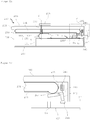
- FIG. 3 FIG. 12 shows an exemplary closure member mover according to an embodiment having a fluid system formed by two overlapping foils, wherein FIG. 3a a plan view of the closing element moving device, the FIG. 3b a sectional view along the line AA the FIG. 3a show the Figure 3c a detailed view of the area B of FIG. 3a with a connecting portion of the foils in the manner of stitching with meshes and the 3d figure a detailed view of the area C of FIG. 3a with a flat connecting portion of the films and ancillary rooms shows. Components and function which are known from the descriptions of the preceding embodiments are omitted here for the sake of clarity.
- the in the FIGS. 3a and 3b Closing element moving device 1 shown has the fluid system 3, which has the first container 5, twice the second container 7 and a connecting line 9, the two second Container 7 fluidly connected to the first container 5.
- the two second container 7 with the for FIG. 2b
- a first or a second closing element 15, 15 ' is coupled to one of the two second containers 7.
- the two closing elements 15, 15' are connected to the second containers 7 are connected by connecting means 85 (eg two screws) which pass through the corresponding tabs 83 of the two second containers 7.
- the two closing elements 15, 15 ' are biased into position P' by a respective closing element biasing element 31 (eg a tension spring) ie, the two second containers 7 are deformed (compressed) to occupy the working volume of the first size A.
- a respective closing element biasing element 31 eg a tension spring
- the closing element-moving device 1, the actuating element 11 and an anvil 101 (eg a plate), wherein the actuating element 11 is designed in the manner of a pivot lever which is pivotally connected, for example, with the anvil 101 by means of a pivot axis Z (see. FIG. 3b ).
- the counter-holder 101 is designed to overlap the first container 5, the first container 5 being deformable between the actuating element 11 and the counter-holder 101 in order to deform the first container 5 during a pivoting movement by the actuating element 11 (eg, the counter-holder 101 may also be such be executed to support the two second container 7).
- the moving element 11 is shown in the starting position, in which the first container 5 (eg, at least substantially) is not compressed and thus provides the storage volume of the first size S.
- the fluid system 3 is formed between first and second sheets 103, 103 '(eg, plastic sheets) which overlap and are adjacent and which have the same shape (in FIG. 3a only the first foil 103 is shown covering the second foil 103 '), ie, the fluid system 3 is between the two Foils 103, 103 'formed.
- a contour of the containers 5, 7 and the connecting line 9 are formed by a connecting portion 105, to which the two films 103, 103 'connected to each other (eg welded).
- the fluid system 3 between the two films 103, 103 'by a connecting portion 105 of the two films 103, 103' limited, ie, the outer contour of the container 5, 7 and the connecting line 9 is defined to contain the working fluid in the fluid system 3 ,
- the connecting portion 105 thus serves to seal the fluid system 3 from the environment, wherein the connecting portion 105 depending on its positioning (limiting the contour of the container or connecting line) may be designed differently.
- the connecting portion 105 in a region of the connecting line 9, which is little loaded during actuation of the closing element-moving device 1 (for example, little deformed), and / or in the region of the two second container 7, which upon actuation of the closing element- Movement device 1 are deformed without direct contact with another (eg stiff) component, as a working fluid-tight seam 107 (eg weld) be formed (in the FIG. 3a only the area B is shown with the seam 107, the seam 107 surrounding the connecting line 9 and the two second container 7).
- a working fluid-tight seam 107 eg weld
- the seam 107 along a seam longitudinal direction has a width of about 0.5 mm to about 6 mm, preferably of about 4 mm, in order to secure and permanent connection of the two films 103, 103 'in the connecting portion 105 which as the seam 107 is executed to ensure.
- the seam 107 is provided with a mesh structure, wherein within the seam 107 between the two films 103, 103 'separate mesh spaces 109 are formed, in which the two films 103, 103' are not interconnected (eg welded) are.
- the mesh spaces 109 are separated from each other by lattice-like regions in which the two films 103, 103 'are joined together.
- the mesh spaces 109 are provided which, for example, in the event of a local failure of the seam 107, ensure that the working fluid does not exit the fluid system 3 but collects in one (or more) mesh spaces 109 and increases (eg, crack propagation) in the fabric Seam 107 is stopped. Further, compared to a seam without mesh, the seam 107 with the mesh 109 has greater deformability (flexibility).
- the connecting portion 105 for example, in the region of the first container 5, which is heavily loaded by the contact with the actuating element 11, be designed so that it covers the area of the films 103, 103 '(except for side rooms and passages described below ) completely occupies (hereinafter also: full-surface connecting portion 111), ie, the two films 103, 103 'are here flat connected to each other (eg welded, glued, etc.) to ensure a permanent connection of the two films 103, 103' , Exceptions to the complete connection of the two foils 103, 103 'are, for example, a passage 113, through which passes the pivot axis Z of the actuating element 11, and side rooms 115, which are formed along the contour of the first container 5 (in FIGS FIGS.
- side rooms 115 are shown at a region of the first container 5).
- the side rooms 115 are formed between the two sheets 103, 103 ', wherein the side rooms 115 each have a volume which is smaller than the storage volume of the first size S of the first container 5, for example at least 10 times smaller.
- the side rooms 115 ensure that the working fluid does not exit the fluid system 3, but rather in one or more Adjacent rooms 115 collects and an increase (eg crack propagation) is stopped in connection section 105.
- the types of containers for example, pillows with pistons, lamella or meander containers
- the size of the fluid system 3 the expected number of actuations of the closing element movement device 1, etc., combinations of the seam 107, the Seam 107 with mesh 109, the full-surface connecting portion 111 and the side rooms 115 are made.
- the door 201 is a vault door (for example, a vault cabinet or a vault), and has a door panel 203 and the shutter moving device 1 therein.
- the door leaf 203 has a front side surface 205 (safe outer side, eg an armor plate), a rear side surface 207 (vault inner side, eg a metal sheet) and a peripheral edge 209 surrounding the door leaf 203.
- the door panel 203 is attached to a side portion of the peripheral edge 209 (left in FIG FIG. 4 ) are provided with hinges 211, which are pivotally connected to a door frame 213 (shown in dashed lines).
- the door leaf 203 further includes a pivotable lever 215 coupled to the actuator 11 of the closure member mover 1 and a lock 217 (or passage to the lock) on the front surface 205 which selectively locks the lever 215 (e.g. by means of a key).
- the closing member moving device 1 is formed between the front side surface 205 and the rear side surface 207 in a cavity of the door panel 203.
- the closing element moving device 1 has three closing elements: a first closing element 15 on a upper portion of the peripheral edge 209, a second closing element 15 'at a lateral portion of the peripheral edge 209, which is opposite to the portion with the hinges 211 (right side in the FIG. 4
- the closing elements are retracted in their first position P into the peripheral edge 209 and protrude beyond the peripheral edge 209 of the door leaf 203 in their second position P '(shown) the door leaf 203 is closed in the door frame 213 and the closing elements 15, 15 ', 15 "are in their second position P', the door 201 is locked.
- FIG. 5 an exemplary door is shown with a closing element moving device according to an embodiment, wherein the FIG. 5a a plan view of the door with the closing element moving device, the FIG. 5b a sectional view along the line BB of FIG. 5a shows and the FIG. 5c a detailed view of the area D of FIG. 5b shows.
- the closing member moving device 1 of the door 201 in the FIG. 5a is that for the Figure 1d 1, which in this case is provided with the three closing elements 15, 15 ', 15 ", which have assumed their second position P', that is, the first container 5 is through the connecting line 9 with three second containers 7, and the third container 55 is connected by the connecting line 59 with three second containers 57.
- the components of the fluid system 3 which interact with the first and third closure members 15, 15 '' are analogous, with the components of the fluid system 3 cooperating with the second closure member 15 'being analogously constructed the type that the fluid system 3 is formed between two sheets, ie, the embodiments of the FIGS. 3 to 3d can apply here analogously.
- Descriptions and illustrations of components and functions of the closing element-moving device 1, which already in connection with the Figure 1d and the Figures 3 to 3d are omitted here for the sake of clarity.
- the door 201 further comprises a security container 231, which is arranged between the front side surface 205 of the door leaf 203 and the closing element-moving device 1 and with the closing element-moving device 1, for example, completely overlapping.
- the safety container 231 contains a safety fluid, for example in the same manner as the working fluid of the fluid system 3, which is under a predetermined pressure.
- the predetermined pressure is a predetermined positive pressure relative to the ambient pressure, which is applied to the front side surface 205 of the door panel 203.
- the containment 231 is formed between first and second sheets 233, 233 '(e.g., plastic sheets, for example, of the same material as that of the sheets 103, 103' of the fluid system 3), which overlap and are adjacent to each other.
- An (outer) contour of the containment 231 is formed by a connecting portion 235 to which the two sheets 233, 233 'are joined together (e.g., welded).
- the connection portion 235 of the containment 231 may be the same as the connection portion 105 of the fluid system 3.
- the two sheets 233, 233 'forming the containment 231 are separated from the two sheets 103, 103' forming the fluid system 3 of the closure member mover 1 by a plate 239 (eg, a metal plate) extending between the two sheets closing member moving device 1 and the security container 231 extends.
- a plate 239 eg, a metal plate
- the containment vessel 231 at least substantially completely occupies a space between the front surface of the door panel 203 and the plate 239.
- the lock 217 serves to selectively allow or prohibit pivotal movement of the lever 215 to which the operating member 11 of the shutter driving device 1 is coupled (the structure and function of a lock are widely known, so that its components are not further illustrated here) and are explained). Furthermore, here the lock case fulfills the function of the counter-holder 101 of the fluid system 3, ie forms a support surface for the containers 5, 55, 7, 57. That is, in the door panel 203, the front surface 205, the containment 231, the plate 239, the closure member mover 1 (the fluid system 3), the lock box (the backstop 101), and the back surface 207 are arranged in this order.
- the containment 231 completely covers the fluid system 3 of the closure member mover 1 and the striker to the front face 205 (at least substantially, for example, except for the passage 237 which serves to mechanically couple the lever 215 to the actuator 11 and lock 217) from.
- the door 201 (the door leaf 203) further comprises a securing means to prevent movement of the closing elements 15, 15 ', 15 ", eg when a manipulation (eg force application) is carried out on the door the state in which the door leaf 205 is locked in the door frame 213 by the closure members 15, 15 ', 15 ", the closure members 15, 15', 15” can be locked in their second position P 'when the containment 231 is damaged by the manipulation and the predetermined pressure due to escaping safety fluid is reduced, for example, in a case in which the security container is drilled or damaged by thermal action.
- a manipulation eg force application
- the construction and the function of the securing means are described by way of example, wherein e.g. additionally or alternatively, the first and the third closing element 15, 15 "can / have the securing means.
- the second closing element 15 'of the closing element moving device 1 further comprises a locking portion 241 in the manner of a groove
- the door 201 (the door leaf 203) further comprises a locking element 243 which extends in the direction of the locking portion 241 of the second closing element 15' a biasing means 245, here eg a compression spring is biased to selectively lock the second closure member 15 '.
- the locking element 243 is here L-shaped and has a long and a short leg, wherein on (transversely to) the long leg a pivot axis 249 is executed, through which the locking element 243 is pivotally connected to the door panel 203.
- the short leg is adapted to engage the latching portion 241 in the manner of a latch when the second latching member 15 'is in the second position P'.
- the containment 231 has an actuation portion 247 (bead) which extends away from the containment 231 by the pressure of the safety fluid. That is, in a region of the containment 231 in which the plate 239 is not formed, the containment 231 forms, by the predetermined pressure of the safety fluid, a bead whose size is determined by the pressure of the safety fluid is. For example, when the pressure in the containment vessel 231 is the predetermined pressure, the bead protrudes toward the back surface 207 beyond the plate 239.
- the operation portion 247 of the containment 231 cooperates with the lock member 243 so as to disengage the lock member 243 and the lock portion 241 of the second lock member 15 'in a state in which the pressure of the safety fluid in the containment 231 is the predetermined pressure. and to release the locking member 243 in a state in which the pressure of the safety fluid in the containment vessel 231 is less than the predetermined pressure to biasly engage the locking portion 241 of the two closure member 15 'by the biasing means 245.
- the operating portion 247 contacts the long leg on one side of the pivot axis 249 of the locking member 243 and the biasing means 245 contacts the short leg of the locking member 243 on the other side of the pivot axis to the state in which the pressure in the security container 231 of the predetermined Pressure is to form a balance of forces, which holds the short leg of the locking element 243 of the locking portion 241 of the second closing element 15 'out of engagement.
- the door 201 may be e.g. connected to a control device (not shown) provided with sensors (eg a structure-borne sound sensor, a temperature sensor, a pressure sensor which detects the pressure of the working fluid and / or the pressure of the safety fluid, etc., not shown) in the door leaf 203 be connected to detect a manipulation on the door 201.
- sensors e.g. a structure-borne sound sensor, a temperature sensor, a pressure sensor which detects the pressure of the working fluid and / or the pressure of the safety fluid, etc., not shown
- the first film 233 and / or the second film 233 'of the containment 231 facing the front surface 205 of the door leaf 203 may be provided with an electrically conductive coating, eg, a grid, for contact with a manipulation tool (eg. a drill) to generate an electrical signal (eg, a short circuit) that is detectable by the controller.
- a manipulation tool eg. a drill
Abstract
Eine Schließelement-Bewegungsvorrichtung (1) kann aufweisen: ein Fluidsystem (3) mit einem ersten verformbaren Behälter (5), welcher abhängig von einem Verformungsgrad des ersten Behälters ein Speichervolumen ausbildet, das zwischen einer ersten Größe (S) und einer zweiten Größe (S') variabel ist, einem zweiten verformbaren Behälter (7), welcher abhängig von einem Verformungsgrad des zweiten Behälters ein Arbeitsvolumen ausbildet, das zwischen einer ersten Größe (A) und einer zweiten Größe (A') variabel ist, einer Verbindungsleitung (9), welche den ersten Behälter (5) mit dem zweiten Behälter (7) fluidverbindet, und einem Arbeitsfluid, welches im Fluidsystem (3) enthalten ist, ein Betätigungselement (11), mittels dessen der erste Behälter (5) selektiv verformbar ist, um das Speichervolumen zwischen der ersten Größe (S) und der zweiten Größe (S') zu variieren, und ein Schließelement (15), welches zwischen einer ersten Position (P) und einer zweiten Position (P') bewegbar ist und mit dem zweiten Behälter (7) gekuppelt ist, wobei, wenn das Speichervolumen des ersten Behälters (5) durch das Betätigungselement (11) variiert wird, das Arbeitsfluid aus dem Speichervolumen ausgeleitet oder in das Speichervolumen eingeleitet wird, hierdurch das Arbeitsvolumen des zweiten Behälters (7) variiert wird und der zweite Behälter (7) verformt wird, um das Schließelement (15) zwischen der ersten Position (P) und der zweiten Position (P') zu bewegen.A closing element movement device (1) can have: a fluid system (3) with a first deformable container (5) which, depending on a degree of deformation of the first container, forms a storage volume which is between a first size (S) and a second size (S ') is variable, a second deformable container (7) which, depending on a degree of deformation of the second container, forms a working volume which is variable between a first size (A) and a second size (A'), a connecting line (9), which fluidly connects the first container (5) to the second container (7), and a working fluid, which is contained in the fluid system (3), an actuating element (11), by means of which the first container (5) can be selectively deformed, around the storage volume to vary between the first size (S) and the second size (S '), and a closing element (15) which is movable between a first position (P) and a second position (P') and with which second container (7) is coupled, wherein if the storage volume of the first container (5) is varied by the actuating element (11), the working fluid is discharged from the storage volume or introduced into the storage volume, thereby the working volume of the second container (7) is varied and the second container (7) is deformed to move the closing element (15) between the first position (P) and the second position (P ').
Description
Die Erfindung betrifft eine Schließelement-Bewegungsvorrichtung und eine Tür, welche diese aufweist.The invention relates to a closing element movement device and a door, which has these.
Schwenktüren, z.B. für Tresore, Tresorräume, etc., sind mittels entsprechender Schließelemente, z.B. Riegel, Bolzen, Leisten, etc., verriegelbar, um einen Zugang zu Räumen sicher und dauerhaft verhindern zu können, sodass nur berechtigte Personen zu diesen Räumen Zugang haben. Beispielsweise in dem Fall von Tresortüren sind üblicher Weise mehrere Schließelemente in einem Türblatt davon bereitgestellt, welche mit verschiedenen Bereichen eines Türrahmens durch ein Riegelwerk in Eingriff bringbar sind, um auch bei Gewaltanwendung auf die Tür das Türblatt im Türrahmen sicher zu verriegeln. Im Falle eines berechtigten Öffnens werden die Schließelemente mittels des Riegelwerks gemeinsam betätigt, beispielsweise nach einer Authentifizierung durch ein Schlüssel-Schloss-System, ein Zahlenschlosssystem, etc., um die Tür zu entriegeln und das Türblatt öffnen zu können. Derartige Riegelwerke sind mechanisch komplex und in der Herstellung teuer. Weiter benötigen die üblichen Riegelwerke in dem beispielhaften Fall einer Tresortür viel Bauraum im Inneren des Tresors, da das Riegelwerk zum Manipulationsschutz auf der Rückseite des Türblatts angeordnet ist, wodurch nutzbares Innenraumvolumen des Tresors verloren geht.Swing doors, e.g. for safes, vaults, etc., are closed by means of appropriate closing elements, e.g. Latches, bolts, strips, etc., lockable, in order to prevent access to rooms safely and permanently, so that only authorized persons have access to these rooms. For example, in the case of vault doors, there are conventionally provided a plurality of shutter members in a door leaf thereof engageable with various portions of a door frame by a bolt mechanism to securely lock the door leaf in the door frame even when the door is used violently. In the case of a legitimate opening, the closing elements are actuated together by means of the bolt mechanism, for example after authentication by a key-lock system, a combination lock system, etc., in order to unlock the door and open the door leaf. Such bolt works are mechanically complex and expensive to manufacture. Next require the usual bolt works in the exemplary case of a safe door much space in the interior of the vault, since the bolt mechanism is arranged for tamper protection on the back of the door, whereby usable interior volume of the vault is lost.
Es werden eine Schließelement-Bewegungsvorrichtung und eine Tür mit einer Schließelement-Bewegungsvorrichtung geschaffen, welche eine kostengünstige und platzsparende Anordnung ermöglichen.There are provided a closing member moving device and a door with a closing member moving device, which allow a cost-effective and space-saving arrangement.
Es werden eine Schließelement-Bewegungsvorrichtung gemäß Anspruch 1 und eine Tür gemäß Anspruch 11 bereitgestellt.There is provided a closing member moving device according to
Weitere Ausführungsformen der Schließelement-Bewegungsvorrichtung und der Tür sind in den jeweiligen abhängigen Ansprüchen beschrieben.Other embodiments of the closure member mover and door are described in the respective dependent claims.
Eine Schließelement-Bewegungsvorrichtung gemäß einer beispielhaften Ausführungsform kann z.B. ein Fluidsystem, ein Betätigungselement und ein (z.B. zwei, drei, vier, fünf, sechs, sieben, acht, neun, zehn oder mehr) Schließelement(e) aufweisen. Das Fluidsystem kann z.B. mit einem ersten (z.B. elastisch bzw. reversibel) verformbaren Behälter, einem zweiten (z.B. elastisch bzw. reversibel) verformbaren Behälter und einer Verbindungsleitung bereitgestellt sein, welche den ersten Behälter mit dem zweiten Behälter fluidverbindet. Der erste Behälter kann z.B. abhängig von einem Verformungsgrad des ersten Behälters ein Speichervolumen ausbilden, das zwischen einer ersten Größe und einer zweiten Größe variabel ist (bspw. ist die erste Größe eine Größe, bei welcher z.B. zumindest im Wesentlichen das maximale Speichervolumen im ersten Behälter bereitgestellt ist, und z.B. ist die zweite Größe eine Größe, bei welcher z.B. zumindest im Wesentlichen kein Speichervolumen im ersten Behälter bereitgestellt ist). Der zweite Behälter kann z.B. abhängig von einem Verformungsgrad des zweiten Behälters ein Arbeitsvolumen ausbilden, das zwischen einer ersten Größe und einer zweiten Größe variabel ist (bspw. ist die erste Größe eine Größe, bei welcher z.B. zumindest im Wesentlichen kein Arbeitsvolumen im zweiten Behälter bereitgestellt ist, und z.B. ist die zweite Größe eine Größe, bei welcher z.B. zumindest im Wesentlichen das maximale Arbeitsvolumen im zweiten Behälter bereitgestellt ist). In dem Fluidsystem kann z.B. ein Arbeitsfluid (z.B. eine Flüssigkeit wie Öl, bspw. Hydrauliköl, Wasser, und Mischungen daraus, bspw. mit Additiven zur Langzeitstabilisierung der Flüssigkeit gemischt, oder ein Gas wie bspw. Luft, Stickstoff, inerte Gase, etc.) enthalten sein.For example, a closure member mover according to an example embodiment may include a fluid system, an actuator, and a (eg, two, three, four, five, six, seven, eight, nine, ten, or more) closure members. The fluid system can be provided, for example, with a first (eg elastically or reversibly) deformable container, a second (eg elastically or reversibly) deformable container and a connecting line which fluidly connects the first container to the second container. For example, depending on a degree of deformation of the first container, the first container may form a storage volume that is variable between a first size and a second size (eg, the first size is a size at which, for example, at least substantially the maximum storage volume is provided in the first container and, for example, the second size is a size at which, for example, at least substantially no storage volume is provided in the first container). For example, depending on a degree of deformation of the second container, the second container may form a working volume that is variable between a first size and a second size (eg, the first size is a size at which, for example, at least substantially no working volume is provided in the second container and, for example, the second size is a size at which, for example, at least substantially the maximum working volume is provided in the second container). In the fluid system, for example, a working fluid (eg, a liquid such as oil, eg. Hydraulic oil, water, and mixtures thereof, for example, mixed with additives for long-term stabilization of the liquid, or a gas such as. Air, nitrogen, inert gases, etc.) be included.
Das Betätigungselement (z.B. ein Schwenkhebel, ein Kipphebel, ein Druckknopf, etc.) kann z.B. bewegbar (z.B. schwenkbar, kippbar, verschiebbar, bspw. manuell durch einen Nutzer) ausgeführt sein und kann z.B. den ersten Behälter selektiv verformen (z.B. komprimieren und/oder expandieren), um das Speichervolumen des ersten Behälters zwischen der ersten Größe und der zweiten Größe zu variieren.The actuator (e.g., a pivot lever, a rocker arm, a push button, etc.) may e.g. movable (e.g., pivotable, tiltable, slidable, e.g., manually by a user) and may be e.g. selectively deforming (e.g., compressing and / or expanding) the first container to vary the storage volume of the first container between the first size and the second size.
Das Schließelement (z.B. ein Schließbolzen, ein Schließriegel, ein Schließzapfen, eine Schließleiste, etc.) kann z.B. zwischen einer ersten Position und einer zweiten Position bewegbar (z.B. verschiebbar und/oder schwenkbar) sein und kann z.B. mit dem zweiten Behälter (direkt oder indirekt) gekuppelt sein.The closure member (e.g., a striker, a latch, a striker, a striker, etc.) may e.g. be movable (e.g., displaceable and / or pivotable) between a first position and a second position, and may e.g. be coupled with the second container (directly or indirectly).
Wenn das Speichervolumen des ersten Behälters z.B. durch das Betätigungselement zwischen der ersten Größe und der zweiten Größe variiert (z.B. komprimiert oder expandiert) wird, kann z.B. das Arbeitsfluid aus dem Speichervolumen ausgeleitet oder in das Speichervolumen eingeleitet werden. Durch das Aus- oder Einleiten des Arbeitsfluids aus dem oder in das Speichervolumen des ersten Behälters kann das Arbeitsvolumen des zweiten Behälters zwischen der ersten Größe und der zweiten Größe variiert werden und kann der zweite Behälter verformt (z.B. expandiert oder komprimiert) werden, um das Schließelement zwischen der ersten Position und der zweiten Position zu bewegen.If the storage volume of the first container is e.g. is varied (e.g., compressed or expanded) by the actuator between the first size and the second size, e.g. the working fluid is discharged from the storage volume or introduced into the storage volume. By discharging the working fluid from or into the storage volume of the first container, the working volume of the second container can be varied between the first size and the second size and the second container can be deformed (eg expanded or compressed) around the closure element to move between the first position and the second position.
Beispielsweise kann die erste Größe des Speichervolumens (z.B. zumindest im Wesentlichen) gleich der zweiten Größe des Arbeitsvolumens sein.For example, the first size of the storage volume (e.g., at least substantially) may be equal to the second size of the working volume.
Die Schließelement-Bewegungsvorrichtung kann z.B. ferner ein Schließelement-Vorspannelement (z.B. eine Druck- oder Zugfeder) aufweisen, welches das Schließelement mit einer Vorspannkraft zu einer von der ersten Position und der zweiten Position vorspannt.For example, the closure member mover may further include a closure member biasing member (eg, a compression or extension spring) which biases the closure member to a biasing force to one of the first position and the second position.
Die Schließelement-Bewegungsvorrichtung kann z.B. ferner ein Erster-Behälter-Vorspannelement (z.B. eine Zugfeder, welche außerhalb des ersten Behälters angeordnet und mit diesem gekuppelt ist und/oder eine Druckfeder, welche innerhalb des ersten Behälters angeordnet und mit diesem gekuppelt ist) aufweisen, welches den ersten Behälter zu einer Einnahme der ersten Größe des Speichervolumens hin vorspannt, um in einem Zustand, in welchem der erste Behälter nicht durch das Betätigungselement verformt ist, das Arbeitsfluid aus dem zweiten Behälter abzuziehen und das Arbeitsvolumen des zweiten Behälters zu veranlassen, dessen erste Größe einzunehmen (bspw. kann der erste Behälter selbst derart ausgestaltet sein, um das Erster-Behälter-Vorspannelement integral aufzuweisen, bspw. in der Art einer elastischen Behälterhülle, welche, wenn keine Belastung des Behälters vorliegt, automatisch die erste Größe des Speichervolumens ausbildet).The closure member mover may e.g. and a first container biasing member (eg, a tension spring disposed outside and coupled to the first container and / or a compression spring disposed within and coupled to the first container) for receiving the first container biasing the first size of the storage volume to, in a state in which the first container is not deformed by the actuating element, withdraw the working fluid from the second container and cause the working volume of the second container to assume its first size (eg the first container itself may be configured to include the first container biasing member integrally, for example, in the manner of an elastic container sleeve which, when there is no load on the container, automatically forms the first size of the storage volume).
Das Fluidsystem der Schließelement-Bewegungsvorrichtung kann z.B. ferner einen dritten verformbaren Behälter, einen vierten verformbaren Behälter und eine zweite Verbindungsleitung aufweisen, welche den dritten Behälter mit dem vierten Behälter fluidverbindet (bspw. sind der erste Behälter, der zweite Behälter und die Verbindungsleitung von dem dritten Behälter, dem vierten Behälter und der zweiten Verbindungsleitung separat ausgebildet).The fluid system of the closure member mover may be e.g. further comprising a third deformable container, a fourth deformable container, and a second connection line fluidly connecting the third container to the fourth container (eg, the first container, the second container, and the connecting conduit are the third container, the fourth container, and the second Connecting line formed separately).
Der dritte Behälter kann z.B. abhängig von einem Verformungsgrad des dritten Behälters ein zweites Speichervolumen ausbilden, das zwischen einer ersten Größe und einer zweiten Größe variabel ist (bspw. ist die erste Größe eine Größe, bei welcher z.B. zumindest im Wesentlichen das maximale zweite Speichervolumen im dritten Behälter bereitgestellt ist, und z.B. ist die zweite Größe eine Größe, bei welcher z.B. zumindest im Wesentlichen kein zweites Speichervolumen im dritten Behälter bereitgestellt ist). Der vierte Behälter kann z.B. abhängig von einem Verformungsgrad des vierten Behälters ein zweites Arbeitsvolumen ausbilden, das zwischen einer ersten Größe und einer zweiten Größe variabel ist (bspw. ist die erste Größe eine Größe, bei welcher z.B. zumindest im Wesentlichen kein zweites Arbeitsvolumen im vierten Behälter bereitgestellt ist, und z.B. ist die zweite Größe eine Größe, bei welcher z.B. zumindest im Wesentlichen das maximale zweite Arbeitsvolumen im vierten Behälter bereitgestellt ist).For example, depending on a degree of deformation of the third container, the third container may form a second storage volume that is variable between a first size and a second size (eg, the first size is one size, eg, at least substantially the maximum second storage volume in the third Container is provided, and for example, the second size is a size in which, for example, at least substantially no second storage volume is provided in the third container). The fourth container may, for example, form a second working volume depending on a degree of deformation of the fourth container, that is variable between a first size and a second size (eg, the first size is a size at which, for example, at least substantially no second working volume is provided in the fourth container, and eg, the second size is a size at which, for example, at least Essentially the maximum second working volume is provided in the fourth container).
Weiter kann z.B. auch der dritte Behälter durch das Betätigungselement verformbar sein, um das zweite Speichervolumen des dritten Behälters zwischen der ersten Größe und der zweiten Größe zu variieren, und z.B. kann das Schließelement auch mit dem vierten Behälter gekuppelt sein.Further, e.g. also the third container may be deformable by the actuator to vary the second storage volume of the third container between the first size and the second size, and e.g. the closure element can also be coupled to the fourth container.
Wenn z.B. das zweite Speichervolumen des dritten Behälters durch das Betätigungselement zwischen der ersten Größe und der zweiten Größe variiert (z.B. komprimiert oder expandiert) wird, kann z.B. das Arbeitsfluid aus dem zweiten Speichervolumen des dritten Behälters ausgeleitet oder in das zweite Speichervolumen des dritten Behälters eingeleitet werden. Durch das Aus- oder Einleiten des Arbeitsfluids aus dem oder in das zweite Speichervolumen des dritten Behälters kann das zweite Arbeitsvolumen des vierten Behälters zwischen der ersten Größe und der zweiten Größe variiert werden und kann der vierte Behälter verformt werden, um das Schließelement von der zweiten Position zur ersten Position zu bewegen. Das Betätigungselement kann z.B. derart eingerichtet sein, dass von ihm selektiv nur der erste Behälter oder der dritte Behälter betätigbar ist.If e.g. the second storage volume of the third container is varied (e.g., compressed or expanded) by the actuator between the first size and the second size, e.g. the working fluid is discharged from the second storage volume of the third container or introduced into the second storage volume of the third container. By discharging the working fluid from or into the second storage volume of the third container, the second working volume of the fourth container may be varied between the first size and the second size, and the fourth container may be deformed to move the closure member from the second position to move to the first position. The actuator may e.g. be set up so that selectively only the first container or the third container can be actuated by it.
Beispielsweise können einer, mehrere oder alle der Behälter in einer Lamellen-, Mäander- oder Kissengestalt ausgebildet sein.For example, one, several or all of the containers may be formed in a lamella, meander or cushion shape.
Das Fluidsystem kann z.B. zwischen zwei sich überlappenden, benachbarten Folien (z.B. Kunststofffolien, Folien-Laminate, bspw. aus einer Kunststofffolie, einer Aluminiumfolie und/oder einer Textilschicht; bspw. können beide Folien gleich sein, bspw. aus dem gleichen Material bestehen, und/oder die gleiche Dicke/Größe haben, oder können voneinander verschieden sein) ausgebildet sein und kann z.B. eine Kontur der Behälter (z.B. eine Außenkontur, bspw. in einer Ebene zwischen den beiden Folien) und der (den) Verbindungsleitung(en) durch einen Verbindungsabschnitt ausgebildet sein, an welchem die beiden Folien miteinander verbunden (z.B. verschweißt, verklebt, an-/ eingepresst, vernäht, oder Kombinationen daraus) sind.The fluid system may, for example, be between two overlapping, adjacent films (eg plastic films, film laminates, for example of a plastic film, an aluminum foil and / or a textile layer; for example, both films be the same, for example, consist of the same material, and / or have the same thickness / size, or may be different from each other) and may, for example, a contour of the container (eg an outer contour, for example. In a plane between the two films ) and the connecting line (s) may be formed by a connecting portion at which the two foils are joined together (eg, welded, glued, pressed / pressed, sewn, or combinations thereof).
Beispielsweise kann der Verbindungsabschnitt als eine arbeitsfluid-dichte Naht ausgebildet sein oder kann z.B. der Verbindungsabschnitt zumindest den (z.B. Flächen-)Bereich der beiden Folien einnehmen, optional vollständig einnehmen, in welchem keines vom Behälter und von der Verbindungsleitung ausgebildet ist (bspw. können Öffnungen in den Folien bereitgestellt sein, welche ebenfalls durch den Verbindungsabschnitt umgeben und somit gegen das Speicher- bzw. Arbeitsvolumen fluiddicht sind).For example, the connecting portion may be formed as a working fluid-tight seam or may be e.g. the connecting portion occupy at least the (eg area) area of the two foils, optionally occupy completely, in which none of the container and of the connecting line is formed (for example openings may be provided in the foils, which are also surrounded by the connecting portion and thus against the storage or working volume are fluid-tight).
Die Naht kann z.B. zumindest abschnittsweise (z.B. entlang einer Nahtlängsrichtung) eine Breite von in etwa 0,5 mm bis in etwa 6 mm, bevorzugt von in etwa 4 mm, oder eine Maschenstruktur haben, bei welcher innerhalb der Naht zwischen den beiden Folien voneinander separate Maschenräume ausgebildet sind, in welchen die beiden Folien (z.B. Verbundfolie, hochfeste Kunststofffolie, etc.) nicht miteinander verbunden (z.B. verschweißt) sind (beispielsweise sind die Maschenräume durch gittermäßige Bereiche des Verbindungsabschnitts voneinander getrennt).The seam can e.g. at least in sections (eg along a seam longitudinal direction) have a width of about 0.5 mm to about 6 mm, preferably of about 4 mm, or have a mesh structure in which separate mesh spaces are formed within the seam between the two films, in which the two films (eg composite film, high-strength plastic film, etc.) are not connected to each other (eg welded) (for example, the mesh spaces are separated by lattice-like regions of the connecting portion).
Beispielsweise können entlang der Kontur (z.B. außerhalb des korrespondierenden Verbindungsabschnitts) z.B. des ersten Behälters, des zweiten Behälters, des dritten Behälters, des vierten Behälters, der Verbindungsleitung und/oder der zweiten Verbindungsleitung zwischen den beiden Folien voneinander separate Nebenräume ausgebildet sein, welche jeweilig ein Volumen aufweisen, das kleiner ist als das des korrespondierenden Volumens des Behälters (z.B. des Speichervolumens oder des Arbeitsvolumens) und/oder der Verbindungsleitung, z.B. mindestens 10-mal kleiner ist. Weiter können die Nebenräume z.B. optional durch die Maschenräume der Naht ausgebildet sein.For example, along the contour (eg outside the corresponding connecting portion), for example of the first container, the second container, the third container, the fourth container, the connecting line and / or the second connecting line, separate side rooms may be formed between the two foils Have volume that is smaller than that of the corresponding volume of the container (eg the storage volume or the working volume) and / or the connecting line, for example at least 10 times smaller. Next, the side rooms can be optionally formed by the meshes of the seam, for example.
Eine Tür (z.B. eine Tresortür, bspw. eines Tresorschranks oder eines Tresorraums) gemäß einer beispielhaften Ausführungsform kann z.B. ein Türblatt und die oben beschriebene Schließelement-Bewegungsvorrichtung aufweisen. Das Türblatt kann mit einer Vorderseitenfläche (z.B. einer Panzerplatte, bspw. einer Stahlplatte), einer Rückseitenfläche und einem das Türblatt umgebenden Umfangsrand bereitgestellt sein. Die Schließelement-Bewegungsvorrichtung kann z.B. an der Rückseitenfläche oder in einem Hohlraum angeordnet sein, welcher zwischen der Vorderseitenfläche und der Rückseitenfläche ausgebildet ist. Das Schließelement oder die Schließelemente der Schließelement-Bewegungsvorrichtung kann oder können z.B. in einer von der ersten Position und der zweiten Position über den Umfangsrand des Türblatts hinaus vorstehen.A door (e.g., a vault door, such as a vault cabinet or vault) according to an exemplary embodiment may be used e.g. a door leaf and the closing element moving device described above. The door panel may be provided with a front surface (e.g., an armor plate, such as a steel plate), a rear surface, and a peripheral edge surrounding the door leaf. The closure member mover may e.g. be arranged on the rear side surface or in a cavity which is formed between the front side surface and the rear side surface. The closure member or members of the closure member mover may or may be e.g. projecting beyond the peripheral edge of the door panel in one of the first position and the second position.
Die Tür kann z.B. ferner einen Sicherheitsbehälter aufweisen, welcher zwischen der Vorderseitenfläche des Türblatts und der Schließelement-Bewegungsvorrichtung und mit der Schließelement-Bewegungsvorrichtung überlappend, z.B. optional vollständig überlappend, angeordnet sein kann (bspw. kann der Sicherheitsbehälter zumindest im Wesentlichen die gleiche Größe wie die Vorderseitenfläche haben und mit dieser kongruent angeordnet sein). Der Sicherheitsbehälter kann ein Sicherheitsfluid enthalten (z.B. ein Fluid wie es für das Arbeitsfluid der Schließelement-Bewegungsvorrichtung beschrieben ist), welches unter einem vorbestimmten Druck (z.B. Überdruck, bspw. gegenüber der Außenseite des Türblatts) steht.The door can e.g. further comprising a security container which overlaps between the front side surface of the door leaf and the closing element moving device and with the closing element moving device, e.g. optionally completely overlapping, may be arranged (for example, the security container may at least substantially the same size as the front side surface and be arranged congruent with this). The containment may include a containment fluid (e.g., a fluid as described for the working fluid of the closure member mover) that is under a predetermined pressure (e.g., overpressure, eg, against the outside of the door panel).
Der Sicherheitsbehälter kann z.B. zwischen zwei sich überlappenden, benachbarten Folien (z.B. Folien, wie sie für das Fluidsystem der Schließelement-Bewegungsvorrichtung beschrieben sind) ausgebildet sein. Die Kontur (z.B. Außenkontur, bspw. in einer Ebene zwischen den beiden Folien) des Sicherheitsbehälters kann z.B. durch einen Verbindungsabschnitt ausgebildet sein, an welchem die beiden Folien miteinander verbunden sind (bspw. kann der Verbindungsabschnitt des Sicherheitsbehälters in der Art des Verbindungsabschnitts des Fluidsystems der Schließelement-Bewegungsvorrichtung ausgeführt sein).The security container can eg between two overlapping, adjacent films (eg films, as they are for the fluid system of the closure element movement device are described) may be formed. The contour (eg outer contour, for example in a plane between the two foils) of the security container can be formed, for example, by a connecting section to which the two foils are connected to one another (for example, the connecting section of the containment can be in the manner of the connecting section of the fluid system) Closing element moving device to be executed).
Einerseits kann beispielsweise eine der beiden Folien des Sicherheitsbehälters eine der beiden Folien sein, welche das Fluidsystem der Schließelement-Bewegungsvorrichtung ausbilden (bspw. weist die Tür dann drei miteinander verbundene Folien auf, wobei zwischen jeweils zwei der Folien das Fluidsystem und der Sicherheitsbehälter ausgebildet sind). Andererseits können z.B. die beiden Folien, welche den Sicherheitsbehälter ausbilden, von den beiden Folien, welche das Fluidsystem der Schließelement-Bewegungsvorrichtung ausbilden, durch eine Platte (z.B. Stahlplatte) getrennt sein, welche sich zwischen der Schließelement-Bewegungsvorrichtung und dem Sicherheitsbehälter erstreckt (bspw. weist die Tür (das Türblatt) dann zwei miteinander verbundene Folien des Sicherheitsbehälters und zwei miteinander verbundene Folien des Fluidsystems auf, welche durch die Platte voneinander getrennt sind).On the one hand, for example, one of the two films of the containment can be one of the two films that form the fluid system of the closure element movement device (eg, the door then has three interconnected films, wherein between each two of the films the fluid system and the containment are formed) , On the other hand, e.g. the two films forming the containment are separated from the two films forming the fluid system of the closure member mover by a plate (eg, steel plate) extending between the closure member mover and the containment (eg, the door (the door leaf) then two interconnected foils of the containment and two interconnected foils of the fluid system separated by the plate).
Weiter kann beispielsweise das Schließelement der Schließelement-Bewegungsvorrichtung einen Verriegelungsabschnitt aufweisen (z.B. eine Aussparung oder einen Vorsprung). Weiter kann z.B. das Türblatt ein Verriegelungselement (z.B. eine Klinke, einen Riegel, einen Zapfen, etc.) aufweisen, welches in Richtung zum Verriegelungsabschnitt des Schließelements vorgespannt ist (bspw. durch eine Feder), um das Schließelement selektiv zu verriegeln (bspw. um selektiv mit dem Verriegelungsabschnitt in Eingriff zu gelangen). Zudem kann z.B. der Sicherheitsbehälter einen Betätigungsabschnitt (z.B. einen (z.B. lokalen) Wulst, einen (z.B. lokalen) Kissen-, Mäander- oder Lamellenabschnitt) aufweisen, welcher sich durch den Druck des Sicherheitsfluids vom Sicherheitsbehälter weg erstreckt (bspw. erstreckt sich der Betätigungsabschnitt zu einer vorbestimmten Position, wenn der vorbestimmte Druck des Sicherheitsfluids im Sicherheitsbehälter zur Verfügung steht, und zieht sich von der vorbestimmten Position zurück, wenn der Druck des Sicherheitsfluids im Sicherheitsbehälter geringer ist als der vorbestimmte Druck). Der Verriegelungs- und der Betätigungsabschnitt können z.B. derart eingerichtet sein, dass der Betätigungsabschnitt des Sicherheitsbehälters mit dem Verriegelungselement derart zusammenwirkt, um in einem Zustand, in welchem der Druck des Sicherheitsfluids im Sicherheitsbehälter der vorbestimmte Druck ist, das Verriegelungselement und den Verriegelungsabschnitt des Schließelements außer Eingriff zu halten (z.B. das Verriegelungselement zu sperren), und um in einem Zustand, in welchem der Druck des Sicherheitsfluids im Sicherheitsbehälter geringer ist als der vorbestimmte Druck (z.B. wenn Sicherheitsfluid aus dem Sicherheitsbehälter entweicht), das Verriegelungselement freizugeben, um sich mit dem Verriegelungsabschnitt des Schließelements in Eingriff zu begeben, wodurch das Schließelement z.B. in seiner zweiten Position blockierbar ist.Further, for example, the closing member of the closing member moving device may include a locking portion (eg, a recess or a protrusion). Further, for example, the door panel may include a locking member (eg, a latch, a latch, a pin, etc.) which is biased toward the locking portion of the latch member (eg, by a spring) to selectively lock the latch member (eg, at selectively engage with the locking portion). In addition, for example, the security container an operating section (eg a (eg, local) bead, a (eg, local) pad, meander, or fin portion) which extends away from the containment by the pressure of the safety fluid (eg, the actuation portion extends to a predetermined position when the predetermined pressure of the safety fluid is available in the containment, and retreats from the predetermined position when the pressure of the safety fluid in the containment is less than the predetermined pressure). For example, the lock and operating portions may be configured such that the operation portion of the safety container cooperates with the lock member to disengage the lock member and the lock portion of the lock member in a state where the pressure of the safety fluid in the containment is the predetermined pressure to hold (eg to lock the locking element) and to release the locking element in a state in which the pressure of the safety fluid in the containment is less than the predetermined pressure (eg, when safety fluid escapes from the containment) to interfere with the locking portion of the Closing element to engage, whereby the closing element can be blocked, for example in its second position.
Ausführungsbeispiele der Erfindung sind in den Figuren dargestellt und werden im Folgenden näher erläutert.Embodiments of the invention are illustrated in the figures and are explained in more detail below.
Es zeigen:
Figur 1- das Funktionsprinzip einer Schließelement-Bewegungsvorrichtung in vier Ausführungsformen, wobei die
Figur 1a eine erste Ausführungsform zeigt, dieFigur 1b eine zweite Ausführungsform zeigt, dieFigur 1c eine dritte Ausführungsform zeigt und dieFigur 1d eine vierte Ausführungsform zeigt; - Figur 2
- verschiedene Behälter einer Schließelement-Bewegungsvorrichtung, wobei die
Figur 2a einen Behälter in der Art eines Kissens mit Kolben zeigt, dieFigur 2b einen Behälter mit einer Lammellenstruktur zeigt und dieFigur 2c einen Behälter mit einer Mäanderstruktur zeigt; Figur 3- ein Schließelement-Bewegungsvorrichtung einer Ausführungsform, welche ein Fluidsystem aufweist, das durch zwei miteinander überlappende Folien gebildet ist, wobei die
Figur 3a eine Draufsicht auf die Schließelement-Bewegungsvorrichtung zeigt, dieFigur 3b eine Schnittansicht entlang der Line A-A derFigur 3a zeigt, dieFigur 3c eine Detailansicht des Bereichs B derFigur 3a mit einem Verbindungsabschnitt der Folien in der Art einer Naht mit Maschenräumen zeigt und dieFigur 3d eine Detailansicht des Bereichs C derFigur 3a mit einem flächigen Verbindungsabschnitt der Folien und Nebenräumen zeigt; - Figur 4
- eine Tür mit einer Schließelement-Bewegungsvorrichtung in einer perspektivischen Ansicht; und
Figur 5- eine Tür mit einer Schließelement-Bewegungsvorrichtung gemäß einer Ausführungsform, wobei die
Figur 5a eine Draufsicht zeigt, dieFigur 5b eine Schnittansicht entlang der Line B-B derFigur 5a zeigt und dieFigur 5c eine Detailansicht des Bereichs D derFigur 5b zeigt.
- FIG. 1
- the principle of operation of a closing element-moving device in four embodiments, wherein the
FIG. 1a a first embodiment shows theFIG. 1b shows a second embodiment, theFigure 1c shows a third embodiment and theFigure 1d a fourth embodiment shows; - FIG. 2
- various containers of a closing element moving device, wherein the
FIG. 2a showing a tank in the manner of a pillow with pistons thatFIG. 2b shows a container with a Lammellenstruktur and theFigure 2c shows a container with a meandering structure; - FIG. 3
- a closure member mover of an embodiment having a fluid system formed by two overlapping sheets, wherein the
FIG. 3a a plan view of the closing element moving device, theFIG. 3b a sectional view along the line AA theFIG. 3a show theFigure 3c a detailed view of the area B ofFIG. 3a with a connecting portion of the foils in the manner of stitching with meshes, and the3d figure a detailed view of the area C ofFIG. 3a with a flat connecting portion of the films and side rooms shows; - FIG. 4
- a door with a closing element moving device in a perspective view; and
- FIG. 5
- a door with a closing element moving device according to an embodiment, wherein the
FIG. 5a a top view showsFIG. 5b a sectional view along the line BB ofFIG. 5a shows and theFIG. 5c a detailed view of the area D ofFIG. 5b shows.
In der folgenden ausführlichen Beschreibung wird auf die beigefügten Figuren Bezug genommen, die Teil dieser bilden und in denen zur Veranschaulichung spezifische Ausführungsformen gezeigt sind, in denen die Erfindung ausgeübt werden kann. In dieser Hinsicht wird Richtungsterminologie wie etwa "oben", "unten", "links", "rechts", "vorne", "hinten", usw. mit Bezug auf die Orientierung der beschriebenen Figur(en) verwendet. Da Komponenten von Ausführungsformen in einer Anzahl verschiedener Orientierungen positioniert werden können, dient die Richtungsterminologie zur Veranschaulichung und ist auf keinerlei Weise einschränkend. Es versteht sich, dass andere Ausführungsformen benutzt und strukturelle oder logische Änderungen vorgenommen werden können, ohne von dem Schutzumfang der vorliegenden Erfindung abzuweichen. Es versteht sich, dass die Merkmale der hierin beschriebenen verschiedenen beispielhaften Ausführungsformen miteinander kombiniert werden können, sofern nicht spezifisch anders angegeben (bspw. können verschieden konfigurierte erste, zweite, dritte und vierte Behälter miteinander kombiniert werden und können z.B. eine Mehrzahl von Schließelementen bereitgestellt sein). Die folgende ausführliche Beschreibung ist deshalb nicht in einschränkendem Sinne aufzufassen, und der Schutzumfang der vorliegenden Erfindung wird durch die angefügten Ansprüche definiert.In the following detailed description, reference is made to the accompanying drawings, which form a part hereof, and in which is shown by way of illustration specific embodiments in which the invention may be practiced. In this regard, directional terminology such as "top", "bottom", "left", "right", "front", "rear", etc. used with respect to the orientation of the figure (s) described. Because components of embodiments can be positioned in a number of different orientations, the directional terminology is illustrative and is in no way limiting. It should be understood that other embodiments may be utilized and structural or logical changes may be made without departing from the scope of the present invention. It is understood that the features of the various exemplary embodiments described herein may be combined with each other unless specifically stated otherwise (eg, differently configured first, second, third and fourth containers may be combined with each other and, for example, a plurality of closure members may be provided). , The following detailed description is therefore not to be taken in a limiting sense, and the scope of the present invention is defined by the appended claims.
Im Rahmen dieser Beschreibung werden Begriffe wie z.B. "verbunden", "angebracht" sowie "gekuppelt" verwendet zum Beschreiben sowohl einer direkten als auch einer indirekten Verbindung, einer direkten oder indirekten Anbringung sowie einer direkten oder indirekten Kupplung. In den Figuren werden identische oder ähnliche Elemente mit identischen Bezugszeichen versehen, soweit dies zweckmäßig ist.For the purposes of this description, terms such as e.g. "connected", "attached" and "coupled" used to describe both direct and indirect connection, direct or indirect attachment, and direct or indirect coupling. In the figures, identical or similar elements are provided with identical reference numerals, as appropriate.
Der in dieser Beschreibung verwendete Begriff "in etwa" gibt übliche Toleranzen von ± 5% an.The term "approximately" used in this specification indicates usual tolerances of ± 5%.
In den Figuren können Größen, Dicken, Abstände, etc. von dargestellten Elementen zum Zweck der Anschaulichkeit übertrieben sein (bspw. die Dicken von Folien bzw. deren Abstände zueinander, bspw. in der
Die
Die in der
Weiter weist die Schließelement-Bewegungsvorrichtung 1 ein Betätigungselement 11 in der Art einer linear verschiebbaren Platte auf, welche mit dem ersten Behälter 5 gekuppelt ist. In der
Zudem weist die Schließelement-Bewegungsvorrichtung 1 ein Schließelement 15 in der Art eines Schließriegels auf. Das Schließelement 15 ist zwischen einer ersten Position P und einer zweiten Position P' verschiebbar (Links-Rechts-Richtung der
Bei einer Betätigung der Schließelement-Bewegungsvorrichtung 1 (des Betätigungselements 11) wird das Speichervolumen des ersten Behälters 5 durch das Betätigungselement 11 von der ersten Größe S zur zweiten Größe S' geändert (komprimiert), sodass das Arbeitsfluid aus dem ersten Behälter 5 ausgeleitet wird und durch die Verbindungsleitung 9 in den zweiten Behälter 7 eingeleitet wird. Durch das Ausleiten des Arbeitsfluids aus dem Speichervolumen des ersten Behälters 5 werden der zweite Behälter 7 verformt und das Arbeitsvolumen des zweiten Behälters 7 von der ersten Größe A zur zweiten Größe A' geändert. Die Verformung (Expansion) des zweiten Behälters 7 verschiebt das Schließelement 15 von der ersten Position P zur zweiten Position P'. In umgekehrter Weise kann das Schließelement 15 durch eine Aufwärtsbewegung des Betätigungselements 11 von der zweiten Position P' zur ersten Position P' bewegt werden.Upon operation of the closing member moving device 1 (the operating member 11), the storage volume of the
In der
Die in der
Das heißt, im Ausgangszustand der Schließelement-Bewegungsvorrichtung 1 befindet sich das Schließelement 15 durch das Schließelement-Vorspannelement 31 in der ersten Position P, wobei bei einer Betätigung (Herabdrücken) des Betätigungselements 11 die gleiche Funktion ausgeführt wird, wie sie oben beschrieben ist, wodurch die Vorspannkraft des Schließelement-Vorspannelements 31 überwunden wird und das Schließelement 15 zur zweiten Position P' bewegt wird. Wenn das Betätigungselement 11 nicht mehr betätigt wird (losgelassen wird), so verformt (komprimiert) das Schließelement 15 aufgrund der Vorspannkraft des Schließelement-Vorspannelements 31 den zweiten Behälter 7, um das Arbeitsfluid aus dem zweiten Behälter 7 auszuleiten und das Arbeitsvolumen des zweiten Behälters 7 zu veranlassen, dessen ersten Größe A einzunehmen. Durch das hierzu korrespondierend in den ersten Behälter 5 eingeleitete Arbeitsfluid wird dieser verformt (expandiert), um das Speichervolumen des ersten Behälters 5 zu veranlassen, dessen erste Größe S einzunehmen. Dementsprechend wird das Betätigungselement 11 durch den ersten Behälter 5 in seine Ausgangsposition zurückgebracht.That is, in the initial state of the closing
Weiter sind die für die erste Ausführungsform beschriebenen Kupplungsarten des Betätigungselements 11 mit dem ersten Behälter 5 und des zweiten Behälters 7 mit dem Schließelement 15 in dieser Ausführungsform nicht erforderlich (können jedoch ebenfalls verwendet werden). Zudem ist es möglich, die Kinematik in dieser Ausführungsform umzukehren, d.h., das Schließelement 15 zur zweiten Position P' vorzuspannen und mittels der Betätigung des Betätigungselements 11 zur ersten Position P zu bewegen.Further, the types of coupling of the operating
In der
Die in der
Das Erster-Behälter-Vorspannelement 41 spannt den ersten Behälter 5 zur Einnahme der ersten Größe S des Speichervolumens vor (Entfaltungszustand), um im Ausgangszustand, in welchem der erste Behälter 5 nicht durch das Betätigungselement 11 verformt ist, das Arbeitsfluid aus dem zweiten Behälter 7 abzuziehen und das Arbeitsvolumen des zweiten Behälters 7 zu veranlassen, dessen erste Größe A einzunehmen. Des Weiteren kann z.B. der erste Behälter 5 selbst derart ausgebildet sein, dass er selbständig rückfedernd die erste Größe S des Speichervolumens einnimmt, wenn er durch das Betätigungselement 11 nicht verformt ist, z.B. durch Ausbilden elastischer Rippen an der Außenseite des ersten Behälters 5. Weiter ist hier der zweite Behälter 7 mit dem Schließelement 15 wie in der ersten Ausführungsform gekuppelt.The first
Das heißt, im Ausgangszustand der Schließelement-Bewegungsvorrichtung 1 befindet sich der erste Behälter 5 aufgrund des Erster-Behälter-Vorspannelements 41 in einem Expansionszustand, in welchem er die erste Größe S des Speichervolumens bereitstellt. Hierdurch befindet sich der zweite Behälter 7 in einem Kompressionszustand, in welchem er die erste Größe A des Arbeitsvolumens bereitstellt, um das Schließelement in der ersten Position P zu halten. Bei einer Betätigung (Herabdrücken) des Betätigungselements 11 wird die gleiche Funktion ausgeführt, wie sie oben für die erste und die zweite Ausführungsform beschrieben ist, wodurch die Vorspannkraft des Erster-Behälter-Vorspannelements 41 überwunden wird und das Schließelement 15 zur zweiten Position P' bewegt wird. Wenn das Betätigungselement 11 nicht mehr betätigt wird (losgelassen wird), so verformt (expandiert) das Erster-Behälter-Vorspannelement 41 den ersten Behälter 5, um das Arbeitsfluid aus dem zweiten Behälter 7 auszuleiten und das Arbeitsvolumen des zweiten Behälters 7 zu veranlassen, dessen erste Größe A einzunehmen. Dementsprechend wird das Betätigungselement 11 durch den ersten Behälter 5 in seine Ausgangsposition zurückgebracht.That is, in the initial state of the closing
Weiter ist es möglich, die Kinematik in dieser Ausführungsform umzukehren, d.h., das Schließelement 15 zur zweiten Position P' vorzuspannen und mittels der Betätigung des Betätigungselements 11 zur ersten Position P zu verschieben. Zudem kann z.B. zusätzlich unterstützend das Schließelement-Vorspannelement 31 der zweiten Ausführungsform bereitgestellt sein.Further, it is possible to reverse the kinematics in this embodiment, that is, to bias the closing
In der
Das in der
Das Betätigungselement 11 der Schließelement-Bewegungsvorrichtung 1 ist hier ein Schwenkhebel, welcher mit dem Gegenhalter 13 schwenkbar verbunden ist. Das Betätigungselement 11 ist derart eingerichtet, um selektiv nur den ersten Behälter 5 oder den dritten Behälter 55 zu betätigen (verformen). Hierzu ist das Betätigungselement 11 zwischen dem ersten und dem dritten Behälter 5, 55 angeordnet und durch den Nutzer in Richtung zum einen oder zum anderen vom ersten und vom dritten Behälter 5, 55 schwenkbar (Links-Rechts-Richtung). Analog zum ersten Behälter 5 ist das zweite Speichervolumen des dritten Behälters 55 durch das Betätigungselement 11 zwischen der ersten Größe S2 und der zweiten Größe S2' variierbar.The
Weiter ist das Schließelement 15 auch mit dem vierten Behälter 57 gekuppelt, um das Schließelement 15 selektiv in Richtung zum zweiten Behälter 7 zu verschieben, d.h., ausgehend von der zweiten Position P' zur ersten Position P.Further, the
Bei einer Betätigung der Schließelement-Bewegungsvorrichtung 1 (des Betätigungselements 11) in Richtung zum ersten Behälter 5 wird das Speichervolumen des ersten Behälters 5 durch das Betätigungselement 11 von der ersten Größe S zur zweiten Größe S' geändert (komprimiert), sodass das Arbeitsfluid aus dem ersten Behälter 5 ausgeleitet wird und durch die Verbindungsleitung 9 in den zweiten Behälter 7 eingeleitet wird. Durch das Ausleiten des Arbeitsfluids aus dem Speichervolumen des ersten Behälters 5 werden der zweite Behälter 7 verformt und das Arbeitsvolumen des zweiten Behälters 7 von der ersten Größe A zur zweiten Größe A' geändert. Die Verformung (Expansion) des zweiten Behälters 7 verschiebt das Schließelement 15 von der ersten Position P zur zweiten Position P'.Upon actuation of the closing element moving device 1 (the actuating element 11) in the direction of the
In umgekehrter Weise, bei einer Betätigung der Schließelement-Bewegungsvorrichtung 1 (des Betätigungselements 11) in Richtung zum dritten Behälter 55 wird das zweite Speichervolumen des dritten Behälters 55 durch das Betätigungselement 11 von der ersten Größe S2 zur zweiten Größe S2' geändert (komprimiert), sodass das Arbeitsfluid aus dem dritten Behälter 55 ausgeleitet wird und durch die zweite Verbindungsleitung 59 in den vierten Behälter 57 eingeleitet wird. Durch das Ausleiten des Arbeitsfluids aus dem zweiten Speichervolumen des dritten Behälters 55 werden der vierte Behälter 57 verformt und das zweite Arbeitsvolumen des vierten Behälters 57 von der ersten Größe A2 zur zweiten Größe A2' geändert. Die Verformung (Expansion) des vierten Behälters 57 verschiebt das Schließelement 15 von der zweiten Position P' zur ersten Position P.Conversely, upon operation of the closing member moving device 1 (the operating member 11) toward the
Die
In der
Im zweiten Behälter 7 ist ein Kolben 71 bereitgestellt, welcher mit der Behälterwand (Folie) verbunden (z.B. verklebt, verschweißt, etc.) ist, um sich beim Verformen des zweiten Behälters 7 zusammen mit der Behälterwand zu bewegen. Somit steht ein Bereich des zweiten Behälters 7 als das Arbeitsvolumen zur Verfügung, während der andere Bereich des zweiten Behälters 7 vom Kolben 71 eingenommen wird. Beispielsweise kann der Kolben 71 abgerundete Ecken und Kanten haben, um die Folie nicht zu verletzen. Der Kolben 71 weist einen Vorsprung 73 auf, welcher an der dem Schließelement 15 zugewandten Seite des zweiten Behälters 7 aus dem zweiten Behälter 7 vorsteht, d.h., die Folie dort durchdringt (bspw. kann der Vorsprung auch durch eine Lasche der Folie gebildet sein). Der Vorsprung 73 ist mit dem Schließelement 15 durch ein Verbindungsmittel 75, bspw. eine Schraube, ein Niet, eine Klebestelle, etc. verbunden, um bei der Verformung des zweiten Behälters 7 das Schließelement 15 zwischen der ersten Position P und der zweiten Position P' hin und her zu bewegen.In the
In dem in der
In dem in der
In der
Der zweite Behälter 7 ist in einer Lamellenstruktur mit einer ersten, einer zweiten und einer dritten Kammer (Lamelle) 81, 81', 81" bereitgestellt, welche in der Folie ausgebildet sind und miteinander fluidverbunden sind. Zusammen bilden die Kammern 81, 81', 81" das Arbeitsvolumen. Der zweite Behälter 7 weist eine Lasche 83 auf, welche an der dem Schließelement 15 zugewandten Seite des zweiten Behälters 7 am zweiten Behälter 7 vorsteht. Die Lasche 83 ist mit dem Schließelement 15 durch ein Verbindungsmittel 85, bspw. eine Schraube, ein Niet, eine Klebestelle, etc. verbunden, um bei der Verformung des zweiten Behälters 7 das Schließelement 15 zwischen der ersten Position P und der zweiten Position P' hin und her zu bewegen. Der zweite Behälter 7 befindet sich durch das Schließelement-Vorspannelement unter einer Zugbelastung, d.h., ist zur Einnahme der ersten Größe A des Arbeitsvolumens vorgespannt.The
In dem in der
In dem in der
In der
Der zweite Behälter 7 ist als mäanderförmig-angeordneter Schlauch ausgeführt, dessen eines Ende mit der Verbindungsleitung 9 verbunden ist und dessen anderes (geschlossenes) Ende das Schließelement 15 kontaktiert. Der zweite Behälter 7 bildet hier beispielsweise vier Schlingen (erste bis vierte Schlinge 91, 91', 91", 91') aus. Der zweite Behälter 7 ist mit dem Schließelement 15 gekuppelt, welches hier durch das Schließelement-Vorspannelement (nicht gezeigt) in die erste Position P vorgespannt ist (vgl. Pfeil in der
Das heißt, in dem in der
Weiter, in dem in der
Die
Die in den
Weiter weist die Schließelement-Bewegungsvorrichtung 1 das Betätigungselement 11 und einen Gegenhalter 101 (z.B. eine Platte) auf, wobei das Betätigungselement 11 in der Art eines Schwenkhebels ausgeführt ist, das z.B. mit dem Gegenhalter 101 mittels einer Schwenkachse Z schwenkbar verbunden ist (vgl.
Das Fluidsystem 3 ist zwischen einer ersten und einer zweiten Folie 103, 103' (z.B. Kunststofffolien) ausgebildet, welche sich überlappen und benachbart sind und welche die gleiche Gestalt haben (in der
Der Verbindungsabschnitt 105 dient somit, das Fluidsystem 3 gegen die Umgebung abzudichten, wobei der Verbindungsabschnitt 105 abhängig von seiner Positionierung (Begrenzung der Kontur der Behälter oder Verbindungsleitung) unterschiedlich ausgeführt sein kann. Beispielsweise kann der Verbindungsabschnitt 105 in einem Bereich der Verbindungsleitung 9, welche bei einer Betätigung der Schließelement-Bewegungsvorrichtung 1 wenig belastet wird (sich bspw. wenig verformt), und/oder im Bereich der beiden zweiten Behälter 7, welche bei einer Betätigung der Schließelement-Bewegungsvorrichtung 1 ohne direkten Kontakt mit einer anderen (z.B. steifen) Komponente verformt werden, als eine arbeitsfluid-dichte Naht 107 (z.B. Schweißnaht) ausgebildet sein (in der
Wie es in der
Weiter, wie es in der
Abhängig von den verwendeten Folien 103, 103', den Behälterarten (bspw. Kissen mit Kolben, Lamellen- oder Mäanderbehälter), der Größe des Fluidsystems 3, der zu erwartenden Betätigungshäufigkeit der Schließelement-Bewegungsvorrichtung 1, etc. können Kombinationen der Naht 107, der Naht 107 mit Maschenräumen 109, des vollflächigen Verbindungsabschnitts 111 und der Nebenräume 115 vorgenommen werden.Depending on the
In der
Die Schließelement-Bewegungsvorrichtung 1 ist zwischen der Vorderseitenfläche 205 und der Rückseitenfläche 207 in einem Hohlraum des Türblatts 203 ausgebildet. Im dargestellten Fall weist die Schließelement-Bewegungsvorrichtung 1 drei Schließelemente auf: Ein erstes Schließelement 15 an einem oberen Abschnitt des Umfangsrands 209, ein zweites Schließelement 15' an einem seitlichen Abschnitt des Umfangsrands 209, welcher zu dem Abschnitt mit den Scharnieren 211 entgegengesetzt ist (rechte Seite in der
In der
Als die Schließelement-Bewegungsvorrichtung 1 der Tür 201 in der
Wie es in der
Der Sicherheitsbehälter 231 ist zwischen einer ersten und einer zweiten Folie 233, 233'(z.B. Kunststofffolien, bspw. aus dem gleichen Material wie das der Folien 103, 103' des Fluidsystems 3) ausgebildet, welche sich überlappen und zueinander benachbart sind. Eine (Außen-)Kontur des Sicherheitsbehälters 231 ist durch einen Verbindungsabschnitt 235 ausgebildet, an welchem die beiden Folien 233, 233' miteinander verbunden (z.B. verschweißt) sind. Beispielsweise kann ein Durchgang 237 im Sicherheitsbehälter 231 vorliegen, welcher durch den Verbindungsabschnitt 235 fluiddicht verschlossen ist. Der Verbindungsabschnitt 235 des Sicherheitsbehälters 231 kann wie der Verbindungsabschnitt 105 des Fluidsystems 3 ausgeführt sein.The
Die beiden Folien 233, 233', welche den Sicherheitsbehälter 231 ausbilden, sind von den beiden Folien 103, 103', welche das Fluidsystem 3 der Schließelement-Bewegungsvorrichtung 1 ausbilden, durch eine Platte 239 (z.B. eine Metallplatte) getrennt, welche sich zwischen der Schließelement-Bewegungsvorrichtung 1 und dem Sicherheitsbehälter 231 erstreckt. Beispielsweise nimmt der Sicherheitsbehälter 231, wenn der vorbestimmte Druck vorliegt, einen Raum zwischen der Vorderseitenfläche des Türblatts 203 und der Platte 239 zumindest im Wesentlichen vollständig ein. An der Rückseitenfläche 207, d.h., im Hohlraum des Türblatts 203, ist ein Schließkasten ausgebildet, in welchem das Schloss 217 (in der
Wie es in den
Anhand des zweiten Schließelements 15' sind der Aufbau und die Funktion des Sicherungsmittels beispielhaft beschrieben, wobei z.B. zusätzlich oder alternativ das erste und das dritte Schließelement 15, 15" das Sicherungsmittel aufweisen kann/können.By means of the second closing element 15 ', the construction and the function of the securing means are described by way of example, wherein e.g. additionally or alternatively, the first and the
Das zweite Schließelement 15' der Schließelement-Bewegungsvorrichtung 1 weist ferner einen Verriegelungsabschnitt 241 in der Art einer Nut auf, und die Tür 201 (das Türblatt 203) weist ferner ein Verriegelungselement 243 auf, welches in Richtung zum Verriegelungsabschnitt 241 des zweiten Schließelements 15' durch ein Vorspannmittel 245, hier z.B. eine Druckfeder, vorgespannt ist, um das zweite Schließelement 15' selektiv zu verriegeln. Das Verriegelungselement 243 ist hier L-förmig ausgeführt und weist einen langen und einen kurzen Schenkel auf, wobei am (quer zum) langen Schenkel eine Schwenkachse 249 ausgeführt ist, durch welche das Verriegelungselement 243 mit dem Türblatt 203 schwenkbar verbunden ist. Der kurze Schenkel ist eingerichtet, um in der Art einer Klinke bzw. Raste mit dem Verriegelungsabschnitt 241 in Eingriff gelangen zu können, wenn sich das zweite Schließelement 15' in der zweiten Position P' befindet.The second closing element 15 'of the closing
Weiter weist der Sicherheitsbehälter 231 einen Betätigungsabschnitt 247 (Wulst) auf, welcher sich durch den Druck des Sicherheitsfluids vom Sicherheitsbehälter 231 weg erstreckt. Das heißt, in einem Bereich des Sicherheitsbehälters 231, in welchem die Platte 239 nicht ausgebildet ist, bildet der Sicherheitsbehälter 231 durch den vorbestimmten Druck des Sicherheitsfluids einen Wulst aus, dessen Größe durch den Druck des Sicherheitsfluids bestimmt ist. Beispielsweise steht der Wulst in Richtung zur Rückseitenfläche 207 über die Platte 239 hinaus, wenn der Druck im Sicherheitsbehälter 231 der vorbestimmte Druck ist.Further, the
Der Betätigungsabschnitt 247 des Sicherheitsbehälters 231 wirkt mit dem Verriegelungselement 243 derart zusammen, um in einem Zustand, in welchem der Druck des Sicherheitsfluids im Sicherheitsbehälter 231 der vorbestimmte Druck ist, das Verriegelungselement 243 und den Verriegelungsabschnitt 241 des zweiten Schließelements 15' außer Eingriff zu halten, und um in einem Zustand, in welchem der Druck des Sicherheitsfluids im Sicherheitsbehälter 231 geringer ist als der vorbestimmte Druck, das Verriegelungselement 243 freizugeben, um sich vorgespannt durch das Vorspannmittel 245 mit dem Verriegelungsabschnitt 241 des zweien Schließelements 15' in Eingriff zu begeben. Hierzu kontaktiert der Betätigungsabschnitt 247 den langen Schenkel auf der einen Seite der Schwenkachse 249 des Verriegelungselements 243 und kontaktiert das Vorspannmittel 245 den kurzen Schenkel des Verriegelungselements 243 an der anderen Seite der Schwenkachse, um in dem Zustand, in welchem der Druck im Sicherheitsbehälter 231 der vorbestimmte Druck ist, ein Kräftegleichgewicht auszubilden, welches den kurzen Schenkel des Verriegelungselements 243 vom Verriegelungsabschnitt 241 des zweiten Schließelements 15' außer Eingriff hält. Wenn aufgrund eines absinkenden Drucks im Sicherheitsbehälter 231 der Druck unter den vorbestimmten Druck abfällt, wird die Kraft geringer, welche durch den Betätigungsabschnitt 247 auf den langen Schenkel des Verriegelungselements 243 ausgeübt wird, sodass die Kraft überwiegt, welche durch das Vorspannmittel 245 auf den kurzen Schenkel des Verriegelungselements 243 ausgeübt wird. In diesem Fall wird der kurze Schenkel des Verriegelungselements 243 durch das Vorspannmittel 245 mit dem Verriegelungsabschnitt 241 des zweiten Schließelements 15' in Eingriff gebracht, sodass das zweite Schließelement 15' in seiner zweiten Position P' blockiert (verriegelt) ist.The
Weiter kann die Tür 201 z.B. mit einer Steuerungseinrichtung (nicht gezeigt) verbunden oder ausgestattet sein, welche mit Sensoren (bspw. einem Körperschallsensor, einem Temperatursensor, einem Drucksensor, welcher den Druck des Arbeitsfluids und/oder den Druck des Sicherheitsfluids erfasst, etc.; nicht gezeigt) im Türblatt 203 verbunden sein, um eine Manipulation an der Tür 201 zu erfassen. Weiter kann z.B. die erste Folie 233 und/oder die zweite Folie 233' des Sicherheitsbehälters 231, welche der Vorderseitenfläche 205 des Türblatts 203 zugewandt ist, mit einer elektrisch leitfähigen Beschichtung, bspw., einem Gitternetz, bereitgestellt sein, um bei Kontakt mit einem Manipulationswerkzeug (bspw. einem Bohrer), ein elektrisches Signal (bspw. einen Kurzschluss) zu erzeugen, welcher von der Steuerungseinrichtung erfassbar ist.Further, the
Claims (15)
wobei die erste Größe (S, S2) des Speichervolumens gleich der zweiten Größe (A', A2') des Arbeitsvolumens ist.Closing element movement device (1) according to claim 1,
wherein the first size (S, S2) of the storage volume is equal to the second size (A ', A2') of the working volume.
wobei das Fluidsystem (3) ferner aufweist:
wobei das Schließelement (15, 15', 15") auch mit dem vierten Behälter (57) gekuppelt ist,
wobei, wenn das zweite Speichervolumen des dritten Behälters (55) durch das Betätigungselement (11) zwischen der ersten Größe (S2) und der zweiten Größe (S2') variiert wird, das Arbeitsfluid aus dem zweiten Speichervolumen des dritten Behälters (55) ausgeleitet oder in das zweite Speichervolumen des dritten Behälters (55) eingeleitet wird, hierdurch das zweite Arbeitsvolumen des vierten Behälters (57) zwischen der ersten Größe (A2) und der zweiten Größe (A2) variiert wird und der vierte Behälter (57) verformt wird, um das Schließelement (15, 15', 15") von der zweiten Position (P') zur ersten Position (P) zu bewegen, und
wobei das Betätigungselement (11) derart eingerichtet ist, dass von ihm selektiv nur der erste Behälter (5) oder der dritte Behälter (55) betätigbar ist.Closing element movement device (1) according to claim 1,
wherein the fluid system (3) further comprises:
the closure element (15, 15 ', 15 ") also being coupled to the fourth container (57),
wherein, when the second storage volume of the third container (55) is varied by the actuator (11) between the first size (S2) and the second size (S2 '), the working fluid is discharged from the second storage volume of the third container (55) is introduced into the second storage volume of the third container (55), whereby the second working volume of the fourth container (57) between the first size (A2) and the second size (A2) is varied and the fourth container (57) is deformed to move the closing element (15, 15 ', 15 ") from the second position (P') to the first position (P), and
wherein the actuating element (11) is arranged such that selectively only the first container (5) or the third container (55) can be actuated by it.
wobei einer, mehrere oder alle der Behälter (5, 55, 7, 57) in einer Lamellen-, Mäander- oder Kissengestalt ausgebildet ist.Closure member movement device (1) according to any one of the preceding claims,
wherein one, several or all of the containers (5, 55, 7, 57) is formed in a lamellar, meander or cushion shape.
wobei das Fluidsystem (3) zwischen zwei sich überlappenden, benachbarten Folien (103, 103') ausgebildet ist und eine Kontur der Behälter (5, 55, 7, 57) und der (den) Verbindungsleitung(en) (9, 59) durch einen Verbindungsabschnitt (105, 107, 111) ausgebildet ist, an welchem die beiden Folien (103, 103') miteinander verbunden sind.Closure member movement device (1) according to any one of the preceding claims,
the fluid system (3) being formed between two overlapping, adjacent foils (103, 103 ') and a contour of the containers (5, 55, 7, 57) and the connecting line (s) (9, 59) a connecting portion (105, 107, 111) is formed, on which the two films (103, 103 ') are interconnected.
wobei der Verbindungsabschnitt (105) als eine arbeitsfluid-dichte Naht (107) ausgebildet ist oder wobei der Verbindungsabschnitt (105) zumindest den Bereich der beiden Folien einnimmt (111), optional vollständig einnimmt, in welchem keines vom Behälter (5, 55, 7, 57)und von der Verbindungsleitung (9, 59) ausgebildet ist.Closure member movement device (1) according to claim 7,
wherein the connecting portion (105) is formed as a working fluid-tight seam (107) or wherein the connecting portion (105) at least the area of the two films occupies (111), optionally completely occupies, in which none of the container (5, 55, 7 , 57) and of the connecting line (9, 59) is formed.
wobei die Naht (107) zumindest abschnittsweise eine Breite von in etwa 0,5 mm bis in etwa 6 mm, bevorzugt von in etwa 4 mm, oder eine Maschenstruktur hat, bei welcher innerhalb der Naht (107) zwischen den beiden Folien (103, 103') voneinander separate Maschenräume (109) ausgebildet sind, in welchen die beiden Folien (103, 103') nicht miteinander verbunden sind.Closing element movement device (1) according to claim 8
wherein the seam (107) at least in sections has a width of about 0.5 mm to about 6 mm, preferably of about 4 mm, or a mesh structure in which within the seam (107) between the two films (103, 103 ') separate mesh spaces (109) are formed, in which the two films (103, 103') are not interconnected.
wobei zumindest entlang der Kontur des ersten Behälters (5), und/oder sofern auf Anspruch 5 rückbezogen, entlang der Kontur des dritten Behälters (55), zwischen den beiden Folien (103, 103') voneinander separate Nebenräume (115) ausgebildet sind, welche jeweilig ein Volumen aufweisen, das kleiner ist als das des Speichervolumens, z.B. mindestens 10-mal kleiner ist,
wobei optional die Nebenräume (115) durch die Maschenräume (109) gemäß Anspruch 9 ausgebildet sind.A closure member moving device (1) according to any one of claims 7 to 9,
wherein at least along the contour of the first container (5), and / or if dependent on claim 5, along the contour of the third container (55), between the two films (103, 103 ') from each other separate side rooms (115) are formed, which each have a volume smaller than that of the storage volume, eg at least 10 times smaller,
wherein optionally the auxiliary spaces (115) are formed by the mesh spaces (109) according to claim 9.
wobei der Sicherheitsbehälter (231) zwischen zwei sich überlappenden, benachbarten Folien (233, 233') ausgebildet ist und die Kontur des Sicherheitsbehälters (231) durch einen Verbindungsabschnitt (235) ausgebildet ist, an welchem die beiden Folien (233, 233') miteinander verbunden sind.Door (201) according to claim 12,
wherein the security container (231) between two overlapping, adjacent films (233, 233 ') is formed and the contour of the security container (231) by a connecting portion (235) is formed, on which the two films (233, 233') with each other are connected.
wobei eine der beiden Folien (233, 233'), welche den Sicherheitsbehälter (231) ausbilden, eine der beiden Folien (103, 103') ist, welche das Fluidsystem (3) der Schließelement-Bewegungsvorrichtung (1) ausbilden, oder
wobei die beiden Folien (233, 233'), welche den Sicherheitsbehälter (231) ausbilden, von den beiden Folien (103, 103'), welche das Fluidsystem (3) der Schließelement-Bewegungsvorrichtung (1) ausbilden, durch eine Platte (239) getrennt sind, welche sich zwischen der Schließelement-Bewegungsvorrichtung (1) und dem Sicherheitsbehälter (231) erstreckt.Door (201) according to claim 13,
wherein one of the two films (233, 233 ') forming the containment (231) is one of the two films (103, 103') forming the fluid system (3) of the closure member mover (1), or
the two foils (233, 233 ') forming the containment (231) of the two foils (103, 103') constituting the fluid system (3) of the closure member mover (1) are supported by a plate (239 ) extending between the closure member mover (1) and the containment (231).
wobei das Schließelement (15, 15' 15") der Schließelement-Bewegungsvorrichtung (1) ferner einen Verriegelungsabschnitt (241) aufweist,
wobei das Türblatt (203) ferner ein Verriegelungselement (243) aufweist, welches in Richtung zum Verriegelungsabschnitt (241) des Schließelements (15, 15', 15") vorgespannt ist, um das Schließelement (243) selektiv zu verriegeln,
wobei der Sicherheitsbehälter (231) ferner einen Betätigungsabschnitt (247) aufweist, welcher sich durch den Druck des Sicherheitsfluids vom Sicherheitsbehälter (231) weg erstreckt, und
wobei der Betätigungsabschnitt (247) des Sicherheitsbehälters (231) mit dem Verriegelungselement (243) derart zusammenwirkt, um in einem Zustand, in welchem der Druck des Sicherheitsfluids im Sicherheitsbehälter (231) der vorbestimmte Druck ist, das Verriegelungselement (243) und den Verriegelungsabschnitt (241) des Schließelements (15), 15', 15") außer Eingriff zu halten, und um in einem Zustand, in welchem der Druck des Sicherheitsfluids im Sicherheitsbehälter (231) geringer ist als der vorbestimmte Druck, das Verriegelungselement (243) freizugeben, um sich mit dem Verriegelungsabschnitt (241) des Schließelements (15, 15', 15") in Eingriff zu begeben.Door (201) according to any one of claims 12 to 14,
wherein the closing member (15, 15 '15 ") of the closing member moving device (1) further comprises a locking portion (241),
the door panel (203) further comprising a locking member (243) biased toward the locking portion (241) of the locking member (15, 15 ', 15 ") for selectively locking the locking member (243),
the containment (231) further comprising an actuation portion (247) extending away from the containment (231) by the pressure of the safety fluid, and
wherein the operation portion (247) of the containment (231) cooperates with the lock member (243) so as to be in a state in which the pressure of the safety fluid in the containment (231) is the predetermined pressure, the lock member (243), and the lock portion (243). 241) of the closure member (15), 15 ', 15 ") and in a state in which the pressure of the safety fluid in the containment (231) is lower than the predetermined pressure to release the locking member (243), to engage with the locking portion (241) of the closure member (15, 15 ', 15 ").
Priority Applications (1)
| Application Number | Priority Date | Filing Date | Title |
|---|---|---|---|
| EP18166790.8A EP3553261B1 (en) | 2018-04-11 | 2018-04-11 | Closing element moving device and door comprising these |
Applications Claiming Priority (1)
| Application Number | Priority Date | Filing Date | Title |
|---|---|---|---|
| EP18166790.8A EP3553261B1 (en) | 2018-04-11 | 2018-04-11 | Closing element moving device and door comprising these |
Publications (2)
| Publication Number | Publication Date |
|---|---|
| EP3553261A1 true EP3553261A1 (en) | 2019-10-16 |
| EP3553261B1 EP3553261B1 (en) | 2021-06-02 |
Family
ID=61971947
Family Applications (1)
| Application Number | Title | Priority Date | Filing Date |
|---|---|---|---|
| EP18166790.8A Active EP3553261B1 (en) | 2018-04-11 | 2018-04-11 | Closing element moving device and door comprising these |
Country Status (1)
| Country | Link |
|---|---|
| EP (1) | EP3553261B1 (en) |
Citations (4)
| Publication number | Priority date | Publication date | Assignee | Title |
|---|---|---|---|---|
| FR399912A (en) * | 1909-02-25 | 1909-07-10 | Louis Victor Ernest Radi | Targette operated by compressed air |
| FR516532A (en) * | 1919-10-28 | 1921-04-20 | Achille Constantaras | Remote opening device of a lock |
| EP0668235A1 (en) * | 1994-02-21 | 1995-08-23 | Inventio Ag | Feeding and unlocking system for lift doors |
| DE102004037299A1 (en) * | 2004-07-31 | 2006-02-16 | Audi Ag | Door actuating device for vehicle door has door handle, adjustable mounted, door latch, transmission element having closed transfer medium system with flexible tubular transmission line whose both sides are arranged per volume shift-element |
-
2018
- 2018-04-11 EP EP18166790.8A patent/EP3553261B1/en active Active
Patent Citations (4)
| Publication number | Priority date | Publication date | Assignee | Title |
|---|---|---|---|---|
| FR399912A (en) * | 1909-02-25 | 1909-07-10 | Louis Victor Ernest Radi | Targette operated by compressed air |
| FR516532A (en) * | 1919-10-28 | 1921-04-20 | Achille Constantaras | Remote opening device of a lock |
| EP0668235A1 (en) * | 1994-02-21 | 1995-08-23 | Inventio Ag | Feeding and unlocking system for lift doors |
| DE102004037299A1 (en) * | 2004-07-31 | 2006-02-16 | Audi Ag | Door actuating device for vehicle door has door handle, adjustable mounted, door latch, transmission element having closed transfer medium system with flexible tubular transmission line whose both sides are arranged per volume shift-element |
Also Published As
| Publication number | Publication date |
|---|---|
| EP3553261B1 (en) | 2021-06-02 |
Similar Documents
| Publication | Publication Date | Title |
|---|---|---|
| EP1296872B1 (en) | Decompression unit for equalizing an explosive air pressure | |
| DE4224551C2 (en) | Airbag device | |
| DE3222202C2 (en) | Locking element for locking cargo items in the cargo hold of aircraft | |
| EP3371052B1 (en) | Overhead luggage compartment for an aircraft | |
| EP2112314B1 (en) | Door assembly with a swinging and sliding function which can be actuated with a single actuation element | |
| DE102018116573A1 (en) | LADERAUMABDECKUNGSSCHLIESSBÜGELBAUGRUPPE | |
| EP2855208B1 (en) | Multifunctional adjustable loading floor | |
| DE2348998A1 (en) | DOOR UNLOCKING, IN PARTICULAR FOR EMERGENCY EXITS | |
| DE102017129427B3 (en) | hinge closure | |
| DE102015111956A1 (en) | Active glove compartment door with locking between locking rods and closers | |
| DE112017004935T5 (en) | Locking device, container door and container | |
| DE102016115215A1 (en) | Side wall assembly for a container and method for its manufacture and container with such a side wall assembly | |
| EP3553261A1 (en) | Closing element moving device and door comprising these | |
| DE3304660A1 (en) | Passenger vehicle | |
| DE102009003341B4 (en) | secure storage | |
| EP2111493B1 (en) | Device for activating pivotable closure elements | |
| DE102017214953B4 (en) | Motor vehicle occupant protection | |
| EP2410113B1 (en) | Mine protection lock and method for unlocking the mine protection lock | |
| CH626708A5 (en) | Device for controlling the opening and closing of a ventilation opening by means of at least one flap | |
| DE102017116999A1 (en) | cover | |
| DE2522516C2 (en) | Drop side lock for a side wall of a truck that can be pivoted by a pressure medium | |
| DE102020100418A1 (en) | Gate device and parking device herewith | |
| DE10111597A1 (en) | Occupant protection system for motor vehicles comprises an airbag cover structure which is provided with hinge points and breakage lines, and is pulled in the direction away from the vehicle interior | |
| DE10210614A1 (en) | Tailgate for motor vehicle has hands-free operation to open window | |
| EP1745992A1 (en) | Airbag module |
Legal Events
| Date | Code | Title | Description |
|---|---|---|---|
| PUAI | Public reference made under article 153(3) epc to a published international application that has entered the european phase |
Free format text: ORIGINAL CODE: 0009012 |
|
| STAA | Information on the status of an ep patent application or granted ep patent |
Free format text: STATUS: THE APPLICATION HAS BEEN PUBLISHED |
|
| AK | Designated contracting states |
Kind code of ref document: A1 Designated state(s): AL AT BE BG CH CY CZ DE DK EE ES FI FR GB GR HR HU IE IS IT LI LT LU LV MC MK MT NL NO PL PT RO RS SE SI SK SM TR |
|
| AX | Request for extension of the european patent |
Extension state: BA ME |
|
| STAA | Information on the status of an ep patent application or granted ep patent |
Free format text: STATUS: REQUEST FOR EXAMINATION WAS MADE |
|
| 17P | Request for examination filed |
Effective date: 20200416 |
|
| RBV | Designated contracting states (corrected) |
Designated state(s): AL AT BE BG CH CY CZ DE DK EE ES FI FR GB GR HR HU IE IS IT LI LT LU LV MC MK MT NL NO PL PT RO RS SE SI SK SM TR |
|
| GRAP | Despatch of communication of intention to grant a patent |
Free format text: ORIGINAL CODE: EPIDOSNIGR1 |
|
| STAA | Information on the status of an ep patent application or granted ep patent |
Free format text: STATUS: GRANT OF PATENT IS INTENDED |
|
| INTG | Intention to grant announced |
Effective date: 20200720 |
|
| GRAS | Grant fee paid |
Free format text: ORIGINAL CODE: EPIDOSNIGR3 |
|
| GRAJ | Information related to disapproval of communication of intention to grant by the applicant or resumption of examination proceedings by the epo deleted |
Free format text: ORIGINAL CODE: EPIDOSDIGR1 |
|
| GRAL | Information related to payment of fee for publishing/printing deleted |
Free format text: ORIGINAL CODE: EPIDOSDIGR3 |
|
| STAA | Information on the status of an ep patent application or granted ep patent |
Free format text: STATUS: REQUEST FOR EXAMINATION WAS MADE |
|
| INTC | Intention to grant announced (deleted) | ||
| GRAP | Despatch of communication of intention to grant a patent |
Free format text: ORIGINAL CODE: EPIDOSNIGR1 |
|
| STAA | Information on the status of an ep patent application or granted ep patent |
Free format text: STATUS: GRANT OF PATENT IS INTENDED |
|
| INTG | Intention to grant announced |
Effective date: 20210113 |
|
| GRAA | (expected) grant |
Free format text: ORIGINAL CODE: 0009210 |
|
| STAA | Information on the status of an ep patent application or granted ep patent |
Free format text: STATUS: THE PATENT HAS BEEN GRANTED |
|
| REG | Reference to a national code |
Ref country code: CH Ref legal event code: EP |
|
| AK | Designated contracting states |
Kind code of ref document: B1 Designated state(s): AL AT BE BG CH CY CZ DE DK EE ES FI FR GB GR HR HU IE IS IT LI LT LU LV MC MK MT NL NO PL PT RO RS SE SI SK SM TR |
|
| REG | Reference to a national code |
Ref country code: GB Ref legal event code: FG4D Free format text: NOT ENGLISH |
|
| REG | Reference to a national code |
Ref country code: AT Ref legal event code: REF Ref document number: 1398559 Country of ref document: AT Kind code of ref document: T Effective date: 20210615 |
|
| REG | Reference to a national code |
Ref country code: IE Ref legal event code: FG4D Free format text: LANGUAGE OF EP DOCUMENT: GERMAN |
|
| REG | Reference to a national code |
Ref country code: DE Ref legal event code: R096 Ref document number: 502018005484 Country of ref document: DE |
|
| REG | Reference to a national code |
Ref country code: LT Ref legal event code: MG9D |
|
| PG25 | Lapsed in a contracting state [announced via postgrant information from national office to epo] |
Ref country code: BG Free format text: LAPSE BECAUSE OF FAILURE TO SUBMIT A TRANSLATION OF THE DESCRIPTION OR TO PAY THE FEE WITHIN THE PRESCRIBED TIME-LIMIT Effective date: 20210902 Ref country code: FI Free format text: LAPSE BECAUSE OF FAILURE TO SUBMIT A TRANSLATION OF THE DESCRIPTION OR TO PAY THE FEE WITHIN THE PRESCRIBED TIME-LIMIT Effective date: 20210602 Ref country code: LT Free format text: LAPSE BECAUSE OF FAILURE TO SUBMIT A TRANSLATION OF THE DESCRIPTION OR TO PAY THE FEE WITHIN THE PRESCRIBED TIME-LIMIT Effective date: 20210602 Ref country code: HR Free format text: LAPSE BECAUSE OF FAILURE TO SUBMIT A TRANSLATION OF THE DESCRIPTION OR TO PAY THE FEE WITHIN THE PRESCRIBED TIME-LIMIT Effective date: 20210602 |
|
| REG | Reference to a national code |
Ref country code: NL Ref legal event code: MP Effective date: 20210602 |
|
| PG25 | Lapsed in a contracting state [announced via postgrant information from national office to epo] |
Ref country code: RS Free format text: LAPSE BECAUSE OF FAILURE TO SUBMIT A TRANSLATION OF THE DESCRIPTION OR TO PAY THE FEE WITHIN THE PRESCRIBED TIME-LIMIT Effective date: 20210602 Ref country code: SE Free format text: LAPSE BECAUSE OF FAILURE TO SUBMIT A TRANSLATION OF THE DESCRIPTION OR TO PAY THE FEE WITHIN THE PRESCRIBED TIME-LIMIT Effective date: 20210602 Ref country code: LV Free format text: LAPSE BECAUSE OF FAILURE TO SUBMIT A TRANSLATION OF THE DESCRIPTION OR TO PAY THE FEE WITHIN THE PRESCRIBED TIME-LIMIT Effective date: 20210602 Ref country code: NO Free format text: LAPSE BECAUSE OF FAILURE TO SUBMIT A TRANSLATION OF THE DESCRIPTION OR TO PAY THE FEE WITHIN THE PRESCRIBED TIME-LIMIT Effective date: 20210902 Ref country code: PL Free format text: LAPSE BECAUSE OF FAILURE TO SUBMIT A TRANSLATION OF THE DESCRIPTION OR TO PAY THE FEE WITHIN THE PRESCRIBED TIME-LIMIT Effective date: 20210602 Ref country code: GR Free format text: LAPSE BECAUSE OF FAILURE TO SUBMIT A TRANSLATION OF THE DESCRIPTION OR TO PAY THE FEE WITHIN THE PRESCRIBED TIME-LIMIT Effective date: 20210903 |
|
| PG25 | Lapsed in a contracting state [announced via postgrant information from national office to epo] |
Ref country code: CZ Free format text: LAPSE BECAUSE OF FAILURE TO SUBMIT A TRANSLATION OF THE DESCRIPTION OR TO PAY THE FEE WITHIN THE PRESCRIBED TIME-LIMIT Effective date: 20210602 Ref country code: NL Free format text: LAPSE BECAUSE OF FAILURE TO SUBMIT A TRANSLATION OF THE DESCRIPTION OR TO PAY THE FEE WITHIN THE PRESCRIBED TIME-LIMIT Effective date: 20210602 Ref country code: RO Free format text: LAPSE BECAUSE OF FAILURE TO SUBMIT A TRANSLATION OF THE DESCRIPTION OR TO PAY THE FEE WITHIN THE PRESCRIBED TIME-LIMIT Effective date: 20210602 Ref country code: PT Free format text: LAPSE BECAUSE OF FAILURE TO SUBMIT A TRANSLATION OF THE DESCRIPTION OR TO PAY THE FEE WITHIN THE PRESCRIBED TIME-LIMIT Effective date: 20211004 Ref country code: EE Free format text: LAPSE BECAUSE OF FAILURE TO SUBMIT A TRANSLATION OF THE DESCRIPTION OR TO PAY THE FEE WITHIN THE PRESCRIBED TIME-LIMIT Effective date: 20210602 Ref country code: ES Free format text: LAPSE BECAUSE OF FAILURE TO SUBMIT A TRANSLATION OF THE DESCRIPTION OR TO PAY THE FEE WITHIN THE PRESCRIBED TIME-LIMIT Effective date: 20210602 Ref country code: SK Free format text: LAPSE BECAUSE OF FAILURE TO SUBMIT A TRANSLATION OF THE DESCRIPTION OR TO PAY THE FEE WITHIN THE PRESCRIBED TIME-LIMIT Effective date: 20210602 Ref country code: SM Free format text: LAPSE BECAUSE OF FAILURE TO SUBMIT A TRANSLATION OF THE DESCRIPTION OR TO PAY THE FEE WITHIN THE PRESCRIBED TIME-LIMIT Effective date: 20210602 |
|
| REG | Reference to a national code |
Ref country code: DE Ref legal event code: R097 Ref document number: 502018005484 Country of ref document: DE |
|
| PLBE | No opposition filed within time limit |
Free format text: ORIGINAL CODE: 0009261 |
|
| STAA | Information on the status of an ep patent application or granted ep patent |
Free format text: STATUS: NO OPPOSITION FILED WITHIN TIME LIMIT |
|
| PG25 | Lapsed in a contracting state [announced via postgrant information from national office to epo] |
Ref country code: DK Free format text: LAPSE BECAUSE OF FAILURE TO SUBMIT A TRANSLATION OF THE DESCRIPTION OR TO PAY THE FEE WITHIN THE PRESCRIBED TIME-LIMIT Effective date: 20210602 |
|
| 26N | No opposition filed |
Effective date: 20220303 |
|
| PG25 | Lapsed in a contracting state [announced via postgrant information from national office to epo] |
Ref country code: AL Free format text: LAPSE BECAUSE OF FAILURE TO SUBMIT A TRANSLATION OF THE DESCRIPTION OR TO PAY THE FEE WITHIN THE PRESCRIBED TIME-LIMIT Effective date: 20210602 |
|
| PG25 | Lapsed in a contracting state [announced via postgrant information from national office to epo] |
Ref country code: IT Free format text: LAPSE BECAUSE OF FAILURE TO SUBMIT A TRANSLATION OF THE DESCRIPTION OR TO PAY THE FEE WITHIN THE PRESCRIBED TIME-LIMIT Effective date: 20210602 |
|
| REG | Reference to a national code |
Ref country code: CH Ref legal event code: PL |
|
| REG | Reference to a national code |
Ref country code: BE Ref legal event code: MM Effective date: 20220430 |
|
| PG25 | Lapsed in a contracting state [announced via postgrant information from national office to epo] |
Ref country code: MC Free format text: LAPSE BECAUSE OF FAILURE TO SUBMIT A TRANSLATION OF THE DESCRIPTION OR TO PAY THE FEE WITHIN THE PRESCRIBED TIME-LIMIT Effective date: 20210602 Ref country code: LU Free format text: LAPSE BECAUSE OF NON-PAYMENT OF DUE FEES Effective date: 20220411 Ref country code: LI Free format text: LAPSE BECAUSE OF NON-PAYMENT OF DUE FEES Effective date: 20220430 Ref country code: CH Free format text: LAPSE BECAUSE OF NON-PAYMENT OF DUE FEES Effective date: 20220430 |
|
| PG25 | Lapsed in a contracting state [announced via postgrant information from national office to epo] |
Ref country code: BE Free format text: LAPSE BECAUSE OF NON-PAYMENT OF DUE FEES Effective date: 20220430 |
|
| REG | Reference to a national code |
Ref country code: GB Ref legal event code: 732E Free format text: REGISTERED BETWEEN 20230323 AND 20230329 |
|
| PG25 | Lapsed in a contracting state [announced via postgrant information from national office to epo] |
Ref country code: IE Free format text: LAPSE BECAUSE OF NON-PAYMENT OF DUE FEES Effective date: 20220411 |
|
| PGFP | Annual fee paid to national office [announced via postgrant information from national office to epo] |
Ref country code: FR Payment date: 20230321 Year of fee payment: 6 |
|
| PGFP | Annual fee paid to national office [announced via postgrant information from national office to epo] |
Ref country code: GB Payment date: 20230321 Year of fee payment: 6 |
|
| REG | Reference to a national code |
Ref country code: GB Ref legal event code: 732E Free format text: REGISTERED BETWEEN 20230525 AND 20230601 |
|
| PGFP | Annual fee paid to national office [announced via postgrant information from national office to epo] |
Ref country code: DE Payment date: 20230321 Year of fee payment: 6 |
|
| REG | Reference to a national code |
Ref country code: DE Ref legal event code: R081 Ref document number: 502018005484 Country of ref document: DE Owner name: DIEBOLD NIXDORF SYSTEMS GMBH, DE Free format text: FORMER OWNER: WINCOR NIXDORF INTERNATIONAL GMBH, 33106 PADERBORN, DE |
|
| PG25 | Lapsed in a contracting state [announced via postgrant information from national office to epo] |
Ref country code: HU Free format text: LAPSE BECAUSE OF FAILURE TO SUBMIT A TRANSLATION OF THE DESCRIPTION OR TO PAY THE FEE WITHIN THE PRESCRIBED TIME-LIMIT; INVALID AB INITIO Effective date: 20180411 |