EP3552730B1 - Punch rivet device - Google Patents
Punch rivet device Download PDFInfo
- Publication number
- EP3552730B1 EP3552730B1 EP19160713.4A EP19160713A EP3552730B1 EP 3552730 B1 EP3552730 B1 EP 3552730B1 EP 19160713 A EP19160713 A EP 19160713A EP 3552730 B1 EP3552730 B1 EP 3552730B1
- Authority
- EP
- European Patent Office
- Prior art keywords
- punch
- drive
- vibrating system
- guiding
- riveting apparatus
- Prior art date
- Legal status (The legal status is an assumption and is not a legal conclusion. Google has not performed a legal analysis and makes no representation as to the accuracy of the status listed.)
- Active
Links
- 238000005304 joining Methods 0.000 claims description 28
- 238000002604 ultrasonography Methods 0.000 claims description 2
- 230000010355 oscillation Effects 0.000 description 9
- 238000004519 manufacturing process Methods 0.000 description 7
- 238000000034 method Methods 0.000 description 4
- 238000005452 bending Methods 0.000 description 3
- 239000000463 material Substances 0.000 description 2
- 230000006978 adaptation Effects 0.000 description 1
- 230000008878 coupling Effects 0.000 description 1
- 238000010168 coupling process Methods 0.000 description 1
- 238000005859 coupling reaction Methods 0.000 description 1
- 230000000694 effects Effects 0.000 description 1
- 239000012530 fluid Substances 0.000 description 1
- 230000003993 interaction Effects 0.000 description 1
- 239000002184 metal Substances 0.000 description 1
- 230000035515 penetration Effects 0.000 description 1
- 238000003825 pressing Methods 0.000 description 1
Images


Classifications
-
- B—PERFORMING OPERATIONS; TRANSPORTING
- B21—MECHANICAL METAL-WORKING WITHOUT ESSENTIALLY REMOVING MATERIAL; PUNCHING METAL
- B21J—FORGING; HAMMERING; PRESSING METAL; RIVETING; FORGE FURNACES
- B21J15/00—Riveting
- B21J15/10—Riveting machines
- B21J15/16—Drives for riveting machines; Transmission means therefor
-
- B—PERFORMING OPERATIONS; TRANSPORTING
- B21—MECHANICAL METAL-WORKING WITHOUT ESSENTIALLY REMOVING MATERIAL; PUNCHING METAL
- B21J—FORGING; HAMMERING; PRESSING METAL; RIVETING; FORGE FURNACES
- B21J15/00—Riveting
- B21J15/02—Riveting procedures
- B21J15/025—Setting self-piercing rivets
-
- B—PERFORMING OPERATIONS; TRANSPORTING
- B21—MECHANICAL METAL-WORKING WITHOUT ESSENTIALLY REMOVING MATERIAL; PUNCHING METAL
- B21J—FORGING; HAMMERING; PRESSING METAL; RIVETING; FORGE FURNACES
- B21J15/00—Riveting
- B21J15/10—Riveting machines
- B21J15/12—Riveting machines with tools or tool parts having a movement additional to the feed movement, e.g. spin
-
- B—PERFORMING OPERATIONS; TRANSPORTING
- B21—MECHANICAL METAL-WORKING WITHOUT ESSENTIALLY REMOVING MATERIAL; PUNCHING METAL
- B21J—FORGING; HAMMERING; PRESSING METAL; RIVETING; FORGE FURNACES
- B21J15/00—Riveting
- B21J15/10—Riveting machines
- B21J15/28—Control devices specially adapted to riveting machines not restricted to one of the preceding subgroups
Definitions
- the present invention relates to a punch riveting device with an oscillating system, in particular a so-called ultrasonic punch riveting device.
- Methods and devices for punch riveting are used to connect at least two components which are in particular planar in a connection area.
- a punch riveting process is characterized in that it is not necessary to pre-punch the components to be connected to one another. Rather, a rivet is pressed into the at least two components by means of a punch or a punch tool, with a correspondingly shaped counter-holder, for example in the form of a die, which interacts with the punch tool, ensuring that the rivet is within a certain way of the components to be connected to one another is deformed in order to establish a non-positive and positive connection between the components and at the same time to avoid penetration of the component facing away from the rivet. From the WO 2015/107351 A1 For example, a punch riveting device is known.
- the DE 10 2016 214 534 A1 which forms the basis for the preamble of claim 1, or the DE 10 2014 203 357 A1 So-called.
- Ultrasonic self-piercing riveting methods and devices are known in which a vibration generator, such as an ultrasonic generator, is used to set one or more components in vibration when the components are connected. This oscillation reduces, for example, the force to be used to press in the rivet.
- a vibration generator such as an ultrasonic generator
- an ultrasonic punch riveting device with so-called X-pliers is known.
- a another variant for the drive in an ultrasonic self-piercing riveting device is disclosed in the DE 199 05 527 A1 .
- the U.S. 3,483,611 A discloses a riveting machine with a stand.
- the invention is based on a punch riveting device for connecting at least two components by means of a rivet, with a punch and a counter holder, between which the at least two components and the rivet can be arranged.
- the self-piercing riveting device has an oscillating system which in turn has the punch and a vibration converter which is coupled or can be coupled to a vibration generator in such a way that the oscillating system can be excited to vibrate.
- the vibration converter can be designed, for example, as an electro-mechanical converter, in particular as a piezo converter, and connected or coupled directly or indirectly via a so-called booster (or amplitude amplifier) to the punch, which then also serves as a sonrode.
- the vibration generator can in particular be a frequency or sound generator, in particular an ultrasonic generator, each preferably also in the form of a function generator, which supplies the vibration converter with a suitable signal so that it is stimulated to vibrate accordingly.
- the punch riveting device also has a drive, by means of which the oscillating system and thus the punch can be acted upon by a force and can be moved in a joining direction in order to insert a rivet arranged between the punch and a component of the at least two components facing the punch into the at least to press in two components.
- a problem with known self-piercing riveting devices with vibration coupling can be that undesired tilting moments occur. This is particularly true when the drive and the oscillating system are arranged in series or one behind the other as seen in the joining direction. However, this can also occur if the drive and the Although oscillating system are arranged in parallel or at least overlapping viewed in the joining direction, the drive is however regularly attached to the frame of the punch riveting device. The same applies to the mentioned ultrasonic punch riveting device with X-pliers.
- a drive and guide unit for guiding the oscillating system in the joining direction which has the drive and is arranged on a frame of the punch riveting device.
- a combined unit for driving and guiding the oscillating system is thus formed.
- This drive and guide unit or a component thereof encloses the oscillating system in a section extending in the joining direction.
- the drive and guide unit has a first component on which the oscillating system is arranged centrally with respect to the joining direction and which encloses a second component of the drive and guide unit in a section extending in the joining direction. Both variants can also be used.
- the drive and guide unit has a guide device for guiding the oscillating system which, as a part or component of the drive and guiding unit, encloses the oscillating system in the section extending in the joining direction.
- the guide device is, in particular, a component formed separately from the drive.
- This guide device is also that part of the drive and guide unit that is arranged on the frame. In this way, a particularly stable guidance of the oscillating system is possible, since it is surrounded directly by the guiding device. Suitable bearings such as roller, ball or slide bearings are then provided in the guide device.
- it can then be guided in the guide device directly or by means of a holder. With a holder, for example, a simpler adaptation of the oscillating system to the guide device, in particular with regard to the geometry, which can often be very specific for the oscillating system, can be achieved.
- the guide device can in particular be tubular with a round or rectangular cross section. On the one hand, this enables a particularly stable guide device, on the other hand, it also enables particularly simple manufacture.
- the drive is advantageously arranged on the frame and coupled to the oscillating system by means of a lever.
- a lever for the drive, for example, a lower force that it has to be able to apply is sufficient, since a translation by means of the lever is possible.
- the lever can in particular be coupled to the oscillating system between a pivot point at which the lever is rotatably mounted on the frame and a point of application of the drive on the lever, for example via a joint. It is also conceivable that the lever is coupled to the oscillating system via the holder, if present.
- the drive is integrated into the guide device and, in particular, is designed as a linear drive. This enables a particularly compact punch riveting device.
- the drive is designed as a hydraulic drive with a cylinder and a piston
- the piston then forming the mentioned first component on which the oscillating system is related is arranged centrally on the joining direction, and the cylinder then forms the second component which (as part of the drive and guide device) encloses the first component in the section extending in the joining direction.
- An additional guiding direction for the drive is therefore initially not necessarily necessary, since this special type of drive already enables a moving component to be enclosed and thus stable guidance. Nevertheless, an even more stable guidance of the oscillation system can be achieved by an additional guide device, in particular designed separately from the drive, which encloses the oscillation system in a corresponding section.
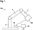
- a production facility 100 is shown in a simplified and schematic manner.
- the production facility 100 can be, for example, an industrial robot in a production hall, for example for an automobile body shop.
- the manufacturing device 100 has a support structure 3 arranged on a floor and two mutually connected and movable arms 4 and 5 arranged thereon. At the end of the arm 5, a punch riveting device 200 according to the invention is arranged in a preferred embodiment, which is only shown schematically here and is described in more detail below.
- a computing unit 80 is shown, which is, for example, a control unit of the punch riveting device 200.
- the computing unit 80 can also be provided as a control unit for the entire production facility, i.e. in addition to the punch riveting device, in particular also for controlling the movable arms.
- display means 90 for example a display, are provided on which, for example, current operating parameters of the punch riveting device can be displayed.
- the element 90 can also be a combined display / input means, for example a touch screen.
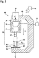
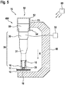
- FIG. 2 a punch riveting device 10, which is not according to the invention, is shown schematically, on which a problem is to be explained which is solved with the present invention.
- the punch riveting device 10 has a frame 60, which is preferably in the form of a C-frame or C-bracket, on which the individual components in a Self-piercing riveting devices are usually arranged in order to be able to assume the desired position relative to one another. Via the frame 60, the punch riveting device 10 can, for example, be attached to an arm as in FIG Figure 1 shown attached.
- the punch riveting device 10 has a punch (or a sonotrode) 15, for example with a round cross section.
- the punch 15 is surrounded radially by a (sleeve-shaped) hold-down device 16 and is arranged to be movable relative to it in the longitudinal direction.
- the hold-down device is preferably attached by means of a spring to a so-called zero amplitude passage of the stamp, ie a position of the stamp at which oscillation amplitudes are zero or at least as low as possible.
- the punch 15 is coupled to a drive 50 which is used to apply a force F in the joining direction R required to press a rivet 20 into the two components 11, 12.
- the drive 50 can for example be controlled by means of the computing unit 80.
- the force F can be specified via a setpoint value and recorded as an actual value.
- the hold-down device 16 is also set up to press against the surface of the component 11 facing the punch 15 with a hold-down force.
- a separate drive can be provided for this purpose, for example.
- the hold-down device can also (as shown here) be coupled to the drive of the punch or to the punch itself, for example by means of a spring.
- a counterholder in the form of a die 18 is arranged on the side of the two components 11, 12 opposite the punch 15 and the hold-down device 16.
- the punch 15 and the die 18, like the hold-down device 16, are arranged in the vertical direction and can be moved relative to one another, the die 18 itself generally not being movable.
- the hold-down 16 and the die 18 serve to clamp or compress the two components 11, 12 between the hold-down 16 and the die 18 during processing by the punch 15.
- the rivet 20 here by way of example a semi-hollow punch rivet, preferably consists of a material that is harder than the materials of the two components 11, 12, at least in the area of a rivet shaft.
- the flat upper side of the rivet facing away from the component 11 is arranged in operative connection with the punch 15, which rests flat against the upper side of the rivet 20.
- the stamp 15 is operatively connected to an (electro-mechanical) vibration converter 30, for example a piezo converter.
- the vibration converter 30 is in turn connected to an (electrical) vibration generator 32, for example an ultrasonic generator.
- an amplitude distance between maximum positive and negative amplitude of a vibration, especially measured at the interface between punch and rivet
- the vibration generator 32 is connected to the computing unit 80 (or can also be part of the computing unit) and can be controlled by it.
- the drive 50 can be, for example, a drive with a ball, roller, planetary thread or thread roller screw drive or the like, which is suitable for applying a force F for pressing the rivet 20 into the components 11, 12.
- a holding device 35 for example in the form of a frame or a rack, is attached to the drive 50.
- a vibration system 39 which in the present case comprises the vibration converter 30, a booster (amplitude amplifier) 31 and the stamp or the sonotrode 15 and the hold-down device 16, is arranged on the holding device 35.
- the high-frequency longitudinal vibration of the joining tool i.e. sonotrode 15, booster 31 and vibration converter 30, can cause the joining tool to wander sideways or to buckle or give way.
- Such lateral forces are in Figure 2 denoted by F Q as an example.
- F Q Such lateral forces
- Figure 2 the tilting of the joining tool or of the entire oscillating system 39 is also shown graphically.
- Such transverse forces are not known in previous, conventional punch riveting devices (without vibration or ultrasound support) in this order of magnitude, since the joining tool is not subjected to high-frequency longitudinal vibrations.
- Punch riveting devices according to the invention are shown schematically in various preferred embodiments.
- the basic components of these punch riveting devices correspond to the components of the punch riveting device 10 according to FIG Figure 2 and in this respect are also provided with the same reference symbols. In this respect, reference is also made to the description there. For the sake of clarity, however, some individual components are not shown.
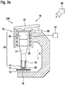
- a punch riveting device 200 according to the invention is shown schematically in a preferred embodiment.
- a drive and guide unit 70 is provided, which has the drive 50 and a guide device 75 as components.
- the guide device 75 here for example tubular with a round cross section, is arranged on the frame. It is conceivable that the guide device is formed integrally with the frame, but the guide device 75 can also be fastened to the frame in a suitable manner.
- the oscillating system 39 is arranged in a holder 35 which is comparable to that in FIG Figure 2 bracket shown can be.
- the oscillating system 39 is guided by means of the holder 35 in the guide device 75 and thus also in the drive and guide unit 70. This is done here by means of suitable bearings such as roller, ball or slide bearings.
- the drive 50 is arranged on the frame and has a lever 51 which, on the one hand, is rotatably attached to the guide device 75, for example by means of a suitable joint, and, on the other hand, is coupled to the holder 35 and thus to the oscillating system 39.
- the drive 50 is correspondingly attached to the lever 51.
- the drive 50 can otherwise, ie in particular with regard to its mode of operation, as in relation to FIG Figure 2 explained be trained.
- the oscillating system 39 can be guided and moved in a particularly stable manner in the joining direction R.
- any tilting or bending resulting from transverse forces can be avoided or at least reduced.
- the guide device 75 which can be designed to be particularly stable, as already explained in more detail at the beginning.
- the punch riveting device 200 is shown in a top view.
- the round cross section of the tubular guide device 75 with a central axis A can be seen here.
- the holder 35, which carries the oscillating system 39 also has a round cross section. Some or all of the parts of the oscillating system 39 can each have a round cross-section, preferably all with the same central axis A.
- bearings with bearing elements 76, for example balls, which are here distributed around the circumference, whereby a particularly uniform and thus stable guidance is achieved.
- the oscillating system can optionally also be guided without the holder 35 in the guide device 75 or the drive and guide unit 70, especially since a guide device with a round cross section is used here.
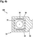
- a punch riveting device 300 according to the invention is shown schematically in a further preferred embodiment.
- the drive 50 is integrated into the guide device 75 as part of the drive and guide unit 70 and is designed in particular as a linear drive.
- Figure 4b which shows the punch riveting device 300 in a plan view
- the cross section of the tubular guide device 75 is rectangular.
- the bearings 76 are arranged here on two opposite sides, components of the drive or linear drive 50 are arranged on the other two sides. In this case, the uniform and stable guidance is achieved by the interaction of the bearings 76 with the drive 50 itself.
- the oscillating system generally has a round cross section
- the use of the holder 35 is expedient here.
- the holder 35 which can then have a rectangular cross section, enables the best possible guidance through the guide device 75 and thus the drive and guide unit 70.
- a self-piercing riveting device 400 is shown schematically.
- the drive and guide unit 70 - in contrast to the punch riveting devices 200 and 300 - the drive and guide are structurally combined.
- the drive 50 itself, which is designed here as a hydraulic drive and is fastened or arranged on the frame 60, serves as a guide.
- the drive 50 has in particular a cylinder 52 with a piston 55 movably arranged therein.
- the drive 50 can be supplied with a suitable hydraulic fluid at the connections 53 and 54.
- the piston 55 here forms the component on which the oscillating system 39 is arranged centrally with respect to the joining direction R, i.e. the aforementioned first component, and the cylinder 52 forms the second component of the drive and guide unit 70, which is the first component or the piston 55 encloses in a section extending in the joining direction.
- the oscillating system 39 can be fastened to the piston 55 in a suitable manner. The use of a suitable holder is also conceivable here.
- a punch riveting device 500 not according to the invention is shown schematically.
- the punch riveting device 500 basically corresponds to the punch riveting device 400 according to FIG Figure 5
- a guide device 75 formed separately from the drive 50 is additionally provided, which can be arranged on the frame 60.
- the guide provided by the drive 50 itself and the guide by means of the guide device 75 are thus combined, so that an even more uniform and stable guide is made possible.
- the guide device 75 can be designed in a manner comparable to the guide device of the punch riveting device 200, but if necessary adapted in length in the joining direction R.
- a holder for the oscillating system 39 for guidance in the guide device 75 can also be provided here.
- the simultaneous use of such a holder for guidance in the guide device 75 and for attachment to the piston 55 is also conceivable.
Landscapes
- Engineering & Computer Science (AREA)
- Mechanical Engineering (AREA)
- Presses And Accessory Devices Thereof (AREA)
Description
Die vorliegende Erfindung betrifft eine Stanznietvorrichtung mit einem Schwingsystem, insbesondere eine sog. Ultraschallstanznietvorrichtung.The present invention relates to a punch riveting device with an oscillating system, in particular a so-called ultrasonic punch riveting device.
Verfahren und Vorrichtungen zum Stanznieten dienen zum Verbinden wenigstens zweier in einem Verbindungsbereich insbesondere eben ausgebildeter Bauteile. Ein Stanznietverfahren zeichnet sich dadurch aus, dass ein Vorlochen der miteinander zu verbindenden Bauteile nicht erforderlich ist. Vielmehr wird ein Niet mittels eines Stempels oder eines Stempelwerkzeugs in die wenigstens zwei Bauteile eingedrückt, wobei durch einen entsprechend geformten Gegenhalter, beispielsweise in Form einer Matrize, der mit dem Stempelwerkzeug zusammenwirkt, sichergestellt ist, dass der Niet sich in einer bestimmten Art und Weise innerhalb der miteinander zu verbindenden Bauteile verformt, um eine kraft- und formschlüssige Verbindung zwischen den Bauteilen herzustellen und gleichzeitig ein Durchdringen des dem Niet abgewandten Bauteils zu vermeiden. Aus der
Weiterhin sind beispielsweise aus der
Erfindungsgemäß wird eine Stanznietvorrichtung mit den Merkmalen des Patentanspruchs 1 vorgeschlagen. Vorteilhafte Ausgestaltungen sind Gegenstand der Unteransprüche sowie der nachfolgenden Beschreibung.According to the invention, a punch riveting device with the features of claim 1 is proposed. Advantageous configurations are the subject of the subclaims and the description below.
Die Erfindung geht aus von einer Stanznietvorrichtung zum Verbinden wenigstens zweier Bauteile mittels eines Niets, mit einem Stempel und einem Gegenhalter, zwischen welchen die wenigstens zwei Bauteile und der Niet anordenbar sind. Dabei weist die Stanznietvorrichtung ein Schwingsystem auf, welches wiederum den Stempel und einen Schwingungskonverter aufweist, der mit einem Schwingungserzeuger derart gekoppelt oder koppelbar ist, dass das Schwingsystem zum Schwingen anregbar ist. Der Schwingungskonverter kann beispielsweise als elektro-mechanischer Wandler, insbesondere als Piezo-Konverter, ausgebildet sein und direkt oder indirekt über einen sog. Booster (bzw. Amplitudenverstärker) mit dem Stempel, der dann auch als Sontrode dient, verbunden bzw. gekoppelt sein. Bei dem Schwingungserzeuger kann es sich insbesondere um einen Frequenz- bzw. Schallgenerator, insbesondere um einen Ultraschallgenerator, jeweils bevorzugt auch in Form eines Funktionsgenerators handeln, der den Schwingungskonverter mit einem geeigneten Signal versorgt, sodass dieser entsprechend zum Schwingen angeregt wird.The invention is based on a punch riveting device for connecting at least two components by means of a rivet, with a punch and a counter holder, between which the at least two components and the rivet can be arranged. The self-piercing riveting device has an oscillating system which in turn has the punch and a vibration converter which is coupled or can be coupled to a vibration generator in such a way that the oscillating system can be excited to vibrate. The vibration converter can be designed, for example, as an electro-mechanical converter, in particular as a piezo converter, and connected or coupled directly or indirectly via a so-called booster (or amplitude amplifier) to the punch, which then also serves as a sonrode. The vibration generator can in particular be a frequency or sound generator, in particular an ultrasonic generator, each preferably also in the form of a function generator, which supplies the vibration converter with a suitable signal so that it is stimulated to vibrate accordingly.
Die Stanznietvorrichtung weist weiterhin einen Antrieb auf, mittels dessen das Schwingsystem und damit der Stempel mit einer Kraft beaufschlagbar und in einer Fügerichtung bewegbar sind, um einen zwischen dem Stempel und einem dem Stempel zugewandten Bauteil der wenigstens zwei Bauteile angeordneten Niet mittels des Stempels in die wenigstens zwei Bauteile einzudrücken.The punch riveting device also has a drive, by means of which the oscillating system and thus the punch can be acted upon by a force and can be moved in a joining direction in order to insert a rivet arranged between the punch and a component of the at least two components facing the punch into the at least to press in two components.
Problematisch bei bekannten Stanznietvorrichtungen mit Schwingungseinkopplung kann sein, dass unerwünschte Kippmomente auftreten. Dies gilt besonders dann, wenn der Antrieb und das Schwingsystem in Fügerichtung gesehen in Reihe bzw. hintereinander angeordnet sind. Jedoch kann dies ebenso auftreten, wenn der Antrieb und das Schwingsystem zwar parallel oder zumindest in Fügerichtung gesehen überlappend angeordnet sind, der Antrieb jedoch regulär am Rahmen der Stanznietvorrichtung angebracht ist. Gleiches gilt für die erwähnte Ultraschall-Stanznietvorrichtung mit X-Zange.A problem with known self-piercing riveting devices with vibration coupling can be that undesired tilting moments occur. This is particularly true when the drive and the oscillating system are arranged in series or one behind the other as seen in the joining direction. However, this can also occur if the drive and the Although oscillating system are arranged in parallel or at least overlapping viewed in the joining direction, the drive is however regularly attached to the frame of the punch riveting device. The same applies to the mentioned ultrasonic punch riveting device with X-pliers.
Solche Kippmomente verursachen eine verstärkte Aufbiegung des gesamten Systems bzw. insbesondere des Rahmens der Stanznietvorrichtung, was dazu führt, dass die durch den Antrieb und das Schwingsystem erzeugten Kräfte bzw. Schwingungen nicht mehr senkrecht auf die Oberflächen der zu verbindenden Bauteile wirken. Dies kann zu unerwünschten Effekten im Fügeprozess führen und insbesondere die Symmetrie der erzeugten Nietverbindung negativ beeinflussen. Entsprechend wird auch die Verbindungsfestigkeit negativ beeinflusst.Such tilting moments cause increased bending of the entire system or, in particular, the frame of the punch riveting device, which means that the forces or vibrations generated by the drive and the vibrating system no longer act perpendicularly on the surfaces of the components to be connected. This can lead to undesirable effects in the joining process and, in particular, have a negative impact on the symmetry of the rivet connection produced. Correspondingly, the connection strength is also negatively affected.
Erfindungsgemäß ist eine Antriebs- und Führungseinheit zur Führung des Schwingsystems in Fügerichtung vorgesehen, die den Antrieb aufweist und an einem Rahmen der Stanznietvorrichtung angeordnet ist. Es wird somit eine kombinierte Einheit für den Anrieb und die Führung des Schwingsystems gebildet. Diese Antriebs- und Führungseinheit bzw. eine Komponente davon umschließt dabei das Schwingsystem in einem sich in Fügerichtung erstreckenden Abschnitt. In einer nicht erfindungsgemäßen Variante weist die Antriebs- und Führungseinheit eine erste Komponente auf, an der das Schwingsystem in Bezug auf die Fügerichtung zentrisch angeordnet ist und die eine zweite Komponente der Antriebs- und Führungseinheit in einem sich in Fügerichtung erstreckenden Abschnitt umschließt. Ebenso können beide Varianten verwendet werden.According to the invention, a drive and guide unit for guiding the oscillating system in the joining direction is provided, which has the drive and is arranged on a frame of the punch riveting device. A combined unit for driving and guiding the oscillating system is thus formed. This drive and guide unit or a component thereof encloses the oscillating system in a section extending in the joining direction. In a variant not according to the invention, the drive and guide unit has a first component on which the oscillating system is arranged centrally with respect to the joining direction and which encloses a second component of the drive and guide unit in a section extending in the joining direction. Both variants can also be used.
Es wird also vorgeschlagen, das Schwingsystem derart zu führen, dass das Schwingsystem oder zumindest eine (bzw. die erste) Komponente der Antriebs- und Führungseinheit, an die das Schwingsystem dann in Fügerichtung gesehen gekoppelt ist, von einer anderen (bzw. der zweiten) Komponente der Antriebs- und Führungseinheit umschlossen wird, was eine deutlich stabilere und verwindungssteifere Führung ermöglicht, als eine einfache Anbindung oder aber auch als eine seitlich angebrachte Führung. Insbesondere wird damit erreicht, dass ein Angriffspunkt der von dem Antrieb bereitgestellten Kraft an dem Schwingsystem in einer sich in Fügerichtung erstreckenden Achse des Schwingsystems liegen kann. Die erwähnten Nachteile werden auf diese Weise vermieden oder zumindest reduziertIt is therefore proposed to guide the oscillation system in such a way that the oscillation system or at least one (or the first) component of the drive and guide unit to which the oscillation system is then coupled, viewed in the joining direction, from another (or the second) Component of the drive and guide unit is enclosed, which enables a significantly more stable and torsion-resistant guide than a simple connection or as a guide attached to the side. In particular, this ensures that a point of application of the force provided by the drive on the oscillating system can lie in an axis of the oscillating system that extends in the joining direction. The disadvantages mentioned are avoided or at least reduced in this way
Erfindungsgemäß weist die Antriebs- und Führungseinheit eine Führungseinrichtung zur Führung des Schwingsystems auf, die als ein Teil bzw. eine Komponente der Antriebs- und Führungseinheit das Schwingsystem in dem sich in Fügerichtung erstreckenden Abschnitt umschließt. Dabei ist die Führungseinrichtung insbesondere eine von dem Antrieb getrennt ausgebildete Komponente. Diese Führungseinrichtung ist zudem derjenige Teil der Antriebs- und Führungseinheit, der an dem Rahmen angeordnet ist. Auf diese Weise ist eine besonders stabile Führung des Schwingsystems möglich, da dieses direkt von der Führungseinrichtung umgeben ist. In der Führungseinrichtung sind dann noch geeignete Lager wie Rollen-, Kugel- oder Gleitlager vorgesehen. Je nach Art des Schwingsystems kann dieses dann unmittelbar oder mittels einer Halterung in der Führungseinrichtung geführt sein. Mit einer Halterung kann beispielsweise eine einfachere Anpassung des Schwingsystems an die Führungseinrichtung, insbesondere hinsichtlich der Geometrie, die für das Schwingsystem oftmals sehr spezifisch sein kann, erreicht werden.According to the invention, the drive and guide unit has a guide device for guiding the oscillating system which, as a part or component of the drive and guiding unit, encloses the oscillating system in the section extending in the joining direction. The guide device is, in particular, a component formed separately from the drive. This guide device is also that part of the drive and guide unit that is arranged on the frame. In this way, a particularly stable guidance of the oscillating system is possible, since it is surrounded directly by the guiding device. Suitable bearings such as roller, ball or slide bearings are then provided in the guide device. Depending on the type of oscillation system, it can then be guided in the guide device directly or by means of a holder. With a holder, for example, a simpler adaptation of the oscillating system to the guide device, in particular with regard to the geometry, which can often be very specific for the oscillating system, can be achieved.
Die Führungseinrichtung kann insbesondere rohrförmig mit rundem oder rechteckigem Querschnitt ausgebildet sein. Damit wird einerseits eine besonders stabile Führungseinrichtung ermöglicht, anderseits aber auch eine besonders einfache Herstellung.The guide device can in particular be tubular with a round or rectangular cross section. On the one hand, this enables a particularly stable guide device, on the other hand, it also enables particularly simple manufacture.
Vorteilhafterweise ist der Antrieb an dem Rahmen angeordnet und mittels eines Hebels an das Schwingsystem gekoppelt. Damit ist für den Antrieb beispielsweise eine geringere Kraft, die er aufbringen können muss, ausreichend, da eine Übersetzung mittels des Hebels möglich ist. Hierzu kann der Hebel insbesondere zwischen einem Drehpunkt, an dem der Hebel an dem Rahmen drehbar gelagert ist, und einem Angriffspunkt des Antriebs an dem Hebel mit dem Schwingsystem gekoppelt sein, beispielsweise über ein Gelenk. Denkbar ist dabei auch, dass der Hebel über die Halterung, wenn vorhanden, an das Schwingsystem gekoppelt ist.The drive is advantageously arranged on the frame and coupled to the oscillating system by means of a lever. For the drive, for example, a lower force that it has to be able to apply is sufficient, since a translation by means of the lever is possible. For this purpose, the lever can in particular be coupled to the oscillating system between a pivot point at which the lever is rotatably mounted on the frame and a point of application of the drive on the lever, for example via a joint. It is also conceivable that the lever is coupled to the oscillating system via the holder, if present.
Alternativ ist es bevorzugt, wenn der Antrieb in die Führungseinrichtung integriert ist, und insbesondere als Linearantrieb ausgebildet ist. Damit wird eine besonders kompakte Stanznietvorrichtung ermöglicht.Alternatively, it is preferred if the drive is integrated into the guide device and, in particular, is designed as a linear drive. This enables a particularly compact punch riveting device.
Weiter ist es -zusätzlich zur Führungseinrichtung - bevorzugt, wenn der Antrieb als hydraulischer Antrieb mit einem Zylinder und einem Kolben ausgebildet ist, wobei der Kolben dann die erwähnte erste Komponente bildet, an der das Schwingsystem in Bezug auf die Fügerichtung zentrisch angeordnet ist, und der Zylinder dann die zweite Komponente bildet, die (als Teil der Antriebs- und Führungseinrichtung) die erste Komponente in dem sich in Fügerichtung erstreckenden Abschnitt umschließt. Damit ist zunächst nicht notwendigerweise eine zusätzliche Führungsrichtung zum Antrieb nötig, da durch diese spezielle Art von Antrieb bereits eine Umschließung einer bewegten Komponente und damit eine stabile Führung ermöglicht werden. Dennoch kann durch eine zusätzliche - insbesondere getrennt vom Antrieb ausgebildete - Führungseinrichtung, die das Schwingsystem in einem entsprechenden Abschnitt umschließt, eine noch stabilere Führung des Schwingsystems erreicht werden.Furthermore, in addition to the guide device, it is preferred if the drive is designed as a hydraulic drive with a cylinder and a piston, the piston then forming the mentioned first component on which the oscillating system is related is arranged centrally on the joining direction, and the cylinder then forms the second component which (as part of the drive and guide device) encloses the first component in the section extending in the joining direction. An additional guiding direction for the drive is therefore initially not necessarily necessary, since this special type of drive already enables a moving component to be enclosed and thus stable guidance. Nevertheless, an even more stable guidance of the oscillation system can be achieved by an additional guide device, in particular designed separately from the drive, which encloses the oscillation system in a corresponding section.
Weitere Vorteile und Ausgestaltungen der Erfindung ergeben sich aus der Beschreibung und der beiliegenden Zeichnung.Further advantages and configurations of the invention emerge from the description and the accompanying drawing.
Es versteht sich, dass die vorstehend genannten und die nachfolgend noch zu erläuternden Merkmale nicht nur in der jeweils angegebenen Kombination, sondern auch in anderen Kombinationen oder in Alleinstellung verwendbar sind, ohne den Rahmen der vorliegenden Erfindung zu verlassen.It goes without saying that the features mentioned above and those yet to be explained below can be used not only in the respectively specified combination, but also in other combinations or alone, without departing from the scope of the present invention.
Die Erfindung ist anhand von Ausführungsbeispielen in der Zeichnung schematisch dargestellt und wird im Folgenden unter Bezugnahme auf die Zeichnung ausführlich beschrieben.The invention is shown schematically in the drawing using exemplary embodiments and is described in detail below with reference to the drawing.
Figurenbeschreibung
- Figur 1
- zeigt vereinfacht und schematisch eine Fertigungseinrichtung mit einer erfindungsgemäßen Stanznietvorrichtung.
- Figur 2
- zeigt schematisch eine nicht erfindungsgemäße Stanznietvorrichtung.
- Figuren 3a und 3b
- zeigen schematisch eine erfindungsgemäße Stanznietvorrichtung in einer bevorzugten Ausführungsform.
- Figuren 4a und 4b
- zeigen schematisch eine erfindungsgemäße Stanznietvorrichtung in einer weiteren bevorzugten Ausführungsform.
Figuren 5 und 6- zeigen schematisch nicht erfindungsgemäße Stanznietvorrichtungen.
- Figure 1
- shows, in a simplified and schematic manner, a production facility with a punch riveting device according to the invention.
- Figure 2
- shows schematically a punch riveting device not according to the invention.
- Figures 3a and 3b
- show schematically a punch riveting device according to the invention in a preferred embodiment.
- Figures 4a and 4b
- show schematically a punch riveting device according to the invention in a further preferred embodiment.
- Figures 5 and 6
- schematically show punch riveting devices not according to the invention.
In
Die Fertigungseinrichtung 100 weist dabei eine auf einem Boden angeordnete Trägerstruktur 3 und zwei daran angeordnete, miteinander verbundene und bewegliche Arme 4 und 5 auf. Am Ende des Armes 5 ist eine erfindungsgemäße Stanznietvorrichtung 200 in einer bevorzugten Ausführungsform angeordnet, welche hier nur schematisch gezeigt und nachfolgend noch detaillierter beschrieben wird.The
Weiterhin ist eine Recheneinheit 80 gezeigt, bei der es sich beispielsweise um eine Steuereinheit der Stanznietvorrichtung 200 handelt. Die Recheneinheit 80 kann zudem auch als Steuereinheit für die gesamte Fertigungseinrichtung, d.h. neben der Stanznietvorrichtung insbesondere auch für die Ansteuerung der beweglichen Arme vorgesehen sein. Weiterhin sind Anzeigemittel 90, beispielsweise ein Display, vorgesehen, auf denen beispielsweise aktuelle Betriebsparameter der Stanznietvorrichtung angezeigt werden können. Es kann sich bei dem Element 90 auch um ein kombiniertes Anzeige-/Eingabemittel, z.B. einen Touchscreen, handeln.Furthermore, a
In
Stanznietvorrichtung in der Regel angeordnet sind, um die gewünschte Position zueinander einnehmen zu können. Über den Rahmen 60 kann die Stanznietvorrichtung 10 beispielsweise an einem Arm wie in
Self-piercing riveting devices are usually arranged in order to be able to assume the desired position relative to one another. Via the
Die Stanznietvorrichtung 10 weist einen Stempel (bzw. eine Sonotrode) 15 auf, beispielhaft mit einem runden Querschnitt. Der Stempel 15 ist von einem (hülsenförmigen) Niederhalter 16 radial umgeben und relativ zu diesem in Längsrichtung beweglich angeordnet. Der Niederhalter ist hierbei vorzugsweise an einem sog. Nullamplitudendurchgang des Stempels, d.h. einer Position des Stempels, an der Schwingungsamplituden Null oder zumindest möglichst gering sind, mittels einer Feder befestigt. Insbesondere ist der Stempel 15 mit einem Antrieb 50 gekoppelt, der dazu dient, eine zum Eindrücken eines Niets 20 in die beiden Bauteile 11, 12 benötigte Kraft F in Fügerichtung R aufzubringen. Der Antrieb 50 kann beispielsweise mittels der Recheneinheit 80 gesteuert werden. Dabei kann die Kraft F beispielsweise über einen Sollwert vorgegeben und als Istwert erfasst werden.The punch
Ebenfalls ist der Niederhalter 16 dazu eingerichtet, gegen die Oberfläche des dem Stempel 15 zugewandten Bauteils 11 mit einer Niederhaltekraft zu drücken. Hierzu kann beispielsweise ein eigener Antrieb vorgesehen sein. Jedoch kann der Niederhalter auch (wie hier gezeigt) an den Antrieb des Stempels oder an den Stempel selbst gekoppelt sein, beispielsweise mittels einer Feder.The hold-down
Auf der dem Stempel 15 und dem Niederhalter 16 gegenüberliegenden Seite der beiden Bauteile 11, 12 ist ein Gegenhalter in Form einer Matrize 18 angeordnet. Der Stempel 15 und die Matrize 18 sind in vertikaler Richtung, wie auch der Niederhalter 16, angeordnet und relativ zueinander bewegbar, wobei die Matrize 18 selbst in der Regel nicht beweglich ist. Der Niederhalter 16 und die Matrize 18 dienen dazu, die beiden Bauteile 11, 12 zwischen dem Niederhalter 16 und der Matrize 18 während der Bearbeitung durch den Stempel 15 einzuspannen bzw. zusammenzudrücken.A counterholder in the form of a die 18 is arranged on the side of the two
Der Niet 20, hier beispielhaft ein Halbhohlstanzniet, besteht bevorzugt aus einem gegenüber den Werkstoffen der beiden Bauteile 11, 12 härteren Material, zumindest im Bereich eines Nietschafts. Die dem Bauteil 11 abgewandte, ebene Oberseite des Niets ist in Wirkverbindung mit dem Stempel 15 angeordnet, der an der Oberseite des Niets 20 flächig anliegt.The
Der Stempel 15 ist mit einem (elektro-mechanischen) Schwingungskonverter 30, beispielsweise einem Piezokonverter, wirkverbunden. Der Schwingungskonverter 30 wiederum ist mit einem (elektrischen) Schwingungserzeuger 32, beispielsweise einem Ultraschallgenerator, verbunden. Auf diese Weise können Schwingungen bzw. Vibrationen erzeugt und auf den Stempel und damit den Niet eingekoppelt werden. Insbesondere werden mittels des Schwingungserzeugers 32 und des Schwingungskonverters 30 Ultraschallschwingungen mit einer Schwingweite (Abstand zwischen maximaler positiver und negativer Amplitude einer Schwingung, insbesondere gemessen an der Schnittstelle zwischen Stempel und Niet) zwischen 10 µm und 110 µm (entspricht einer Amplitude von 5 µm bis 55 µm) und einer Frequenz zwischen 15 kHz und 35 kHz oder ggf. auch höher erzeugt. Der Schwingungserzeuger 32 ist an die Recheneinheit 80 angebunden (oder kann auch Teil der Recheneinheit sein) und kann von dieser angesteuert werden.The
Bei dem Antrieb 50 kann es sich beispielsweise um einen Antrieb mit Kugel-, Rollen-, Planetengewinde- oder Gewinderollenschraubtrieb oder dergleichen handeln, der dazu geeignet ist, eine Kraft F zum Eindrücken des Niets 20 in die Bauteile 11, 12 aufzubringen. An dem Antrieb 50 ist eine Haltevorrichtung 35, beispielsweise in Form eines Rahmens oder eines Gestells, angebracht. An der Haltevorrichtung 35 ist ein Schwingsystem 39, das vorliegend den Schwingungskonverter 30, einen Booster (Amplitudenverstärker) 31 und den Stempel bzw. die Sonotrode 15 sowie den Niederhalter 16 umfasst, angeordnet.The
Beim Betrieb der Stanznietvorrichtung 10, also beim sog. Ultraschall-Stanznieten, kann es durch die hochfrequente Längsschwingung des Fügewerkzeuges, d.h. Sonotrode 15, Booster 31 und Schwingungskonverter 30, zu einem seitlichen Abwandern bzw. Abknicken oder Ausweichen des Fügewerkzeugs kommen. Dies wird durch hohe seitliche Querkräfte hervorgerufen, welche durch eine hämmernde bzw. schlagende Bewegung des Stempels 15 auf den Niet 20 oder durch eine schwingende Bewegung des Stempels 15 in Dauerkontakt mit dem Niet 20 jeweils in Kombination mit geringsten Unebenheiten (wie beispielsweise Bauteilradien, unebene Bleche, unzureichend eingestellte bzw. gefertigte Werkzeugfluchtung, Aufbiegung des Bügels bzw. Rahmens, unsymmetrischer Aufbau des Bügels und dergleichen auftreten können) und kann die Werkzeugstandzeit und die Fügepunktqualität negativ beeinträchtigen.When the self-piercing
Solche Querkräfte sind in
In den
In
Das Schwingsystem 39 ist in einer Halterung 35 angeordnet, welche vergleichbar der in
Der Antrieb 50 wiederum ist an dem Rahmen angeordnet und weist einen Hebel 51 auf, der zum einen drehbar, beispielsweise mittels eines geeigneten Gelenks an der Führungseinrichtung 75 angebracht, und zum anderen an die Halterung 35 und damit an das Schwingsystem 39 gekoppelt ist. Zudem ist der Antrieb 50 entsprechend an dem Hebel 51 befestigt. Der Antrieb 50 kann im Übrigen, d.h. insbesondere hinsichtlich seiner Funktionsweise, wie in Bezug auf
Auf diese Weise ist das Schwingsystem 39 also besonders stabil in Fügerichtung R führbar und bewegbar. Insbesondere können etwaige, aus Querkräften resultierende Verkippungen oder Aufbiegungen vermieden oder zumindest reduziert werden. Dies liegt insbesondere in der besonders stabil ausgestaltbaren Führungseinrichtung 75 begründet, wie dies eingangs bereits näher erläutert wurde.In this way, the oscillating
In
Zudem gezeigt ist eines der Lager mit Lagerelementen 76, beispielsweise Kugeln, die hier um den Umfang verteilt sind, wodurch eine besonders gleichmäßige und damit stabile Führung erreicht wird.Also shown is one of the bearings with bearing
Es sei angemerkt, dass das Schwingsystem ggf. auch ohne die Halterung 35 in der Führungseinrichtung 75 bzw. der Antriebs- und Führungseinheit 70 geführt sein kann, zumal hier eine Führungseinrichtung mit rundem Querschnitt verwendet wird.It should be noted that the oscillating system can optionally also be guided without the
In
In
Da das Schwingsystem in aller Regel einen runden Querschnitt aufweist, ist hier der Einsatz der Halterung 35 zweckmäßig. Durch die Halterung 35, die dann einen rechteckigen Querschnitt aufweisen kann, ist eine möglichst gute Führung durch die Führungseinrichtung 75 und damit die Antriebs- und Führungseinheit 70 möglich.Since the oscillating system generally has a round cross section, the use of the
Im Übrigen, d.h. insbesondere für andere Komponenten als den Antrieb 50, sei an dieser Stelle auch auf die
In
Der Antrieb 50 weist dabei insbesondere einen Zylinder 52 mit einem darin beweglich angeordneten Kolben 55 auf. An den Anschlüssen 53 und 54 kann der Antrieb 50 mit einem geeigneten Hydraulikfluid versorgt werden.The
Der Kolben 55 bildet hierbei diejenige Komponente, an der das Schwingsystem 39 in Bezug auf die Fügerichtung R zentrisch angeordnet ist, also die erwähnte erste Komponente, und der Zylinder 52 bildet die zweite Komponente der Antriebs- und Führungseinheit 70, die die erste Komponente bzw. den Kolben 55 in einem sich in Fügerichtung erstreckenden Abschnitt umschließt. Das Schwingsystem 39 kann dabei auf geeignete Weise an dem Kolben 55 befestigt sein. Denkbar ist auch hier die Verwendung einer geeigneten Halterung.The
In
Damit werden die durch den Antrieb 50 selbst bereitgestellte Führung und die Führung mittels der Führungseinrichtung 75 kombiniert, sodass eine noch gleichmäßigere und stabilere Führung ermöglicht wird. Die Führungseinrichtung 75 kann dabei vergleichbar der Führungseinrichtung der Stanznietvorrichtung 200 ausgebildet sein, ggf. jedoch angepasst in der Länge in Fügerichtung R.The guide provided by the
Ebenso kann hier zusätzlich, wie bei der Stanznietvorrichtung 200, eine Halterung für das Schwingsystem 39 zur Führung in der Führungseinrichtung 75 vorgesehen sein. Denkbar ist auch die gleichzeitige Verwendung einer solchen Halterung zur Führung in der Führungseinrichtung 75 und zur Befestigung an dem Kolben 55.As with the punch
Claims (8)
- Punch-riveting apparatus (200, 300, 400, 500) for connecting at least two component parts (11, 12) by means of a rivet (20), having a punch (15) and a dolly (18), between which the at least two component parts (11, 12) and the rivet (20) are arrangeable,
having a vibrating system (39) having the punch (15) and a vibration converter (30) that is coupled or able to be coupled to a vibration generator (32) such that the vibrating system (39) is able to be excited to vibrate, and having a drive (50), by means of which the vibrating system (39) and thus the punch (15) are able to be subjected to a force (F) and are movable in a joining direction (R) in order to push a rivet (20) arranged between the punch (15) and a component part (11), facing the punch, of the at least two component parts into the at least two component parts (11, 12) by means of the punch (15), characterized by
a combined driving and guiding unit (70) for guiding the vibrating system (39) by means of bearings in the driving and guiding unit (70) and in the joining direction (R), which has the drive (50) and is arranged on a frame (60) of the punch-riveting apparatus, and
which surrounds the vibrating system (39) in a portion extending in the joining direction (R), wherein the driving and guiding unit (70) has a guiding device (75) for guiding the vibrating system (39) by means of bearings in the guiding unit (70), which, as part of the driving and guiding unit (70), surrounds the vibrating system (39) in the portion extending in the joining direction, and which is that part of the driving and guiding unit (70) that is arranged on the frame (60). - Punch-riveting apparatus (200, 300, 500) according to Claim 1, wherein the guiding device (75) is a component formed separately from the drive (50).
- Punch-riveting apparatus (200, 300) according to Claim 2, wherein the vibrating system (39) is guided directly or by means of a holder (35) in the guiding device (75).
- Punch-riveting apparatus (200, 300) according to either of Claims 2 and 3, wherein the guiding device (75) is formed in a tubular manner with a round or rectangular cross section.
- Punch-riveting apparatus (200) according to one of the preceding claims, wherein the drive (50) is arranged on the frame (60) and is coupled to the vibrating system (39) by means of a lever (51).
- Punch-riveting apparatus (300) according to one of the preceding claims, wherein the drive (50) is integrated in the guiding device (75) and is in particular in the form of a linear drive.
- Punch-riveting apparatus (200, 300, 400, 500) according to one of the preceding claims, wherein the driving and guiding unit (70) is configured such that a point of application of the force provided by the drive (50) on the vibrating system lies on an axis, extending in the joining direction, of the vibrating system (39).
- Punch-riveting apparatus (200, 300, 400, 500) according to one of the preceding claims, wherein the vibration generator (32) is in the form of a sound generator, in particular of an ultrasound generator.
Applications Claiming Priority (1)
| Application Number | Priority Date | Filing Date | Title |
|---|---|---|---|
| DE102018205531.9A DE102018205531A1 (en) | 2018-04-12 | 2018-04-12 | Stanznietvorrichtung |
Publications (2)
| Publication Number | Publication Date |
|---|---|
| EP3552730A1 EP3552730A1 (en) | 2019-10-16 |
| EP3552730B1 true EP3552730B1 (en) | 2021-01-27 |
Family
ID=65717746
Family Applications (1)
| Application Number | Title | Priority Date | Filing Date |
|---|---|---|---|
| EP19160713.4A Active EP3552730B1 (en) | 2018-04-12 | 2019-03-05 | Punch rivet device |
Country Status (2)
| Country | Link |
|---|---|
| EP (1) | EP3552730B1 (en) |
| DE (1) | DE102018205531A1 (en) |
Family Cites Families (7)
| Publication number | Priority date | Publication date | Assignee | Title |
|---|---|---|---|---|
| US3483611A (en) * | 1966-08-12 | 1969-12-16 | Cavitron Corp | Methods and apparatus for assembling parts together by ultrasonic energy |
| DE19905527B4 (en) * | 1999-02-10 | 2006-11-23 | Böllhoff GmbH | Device for joining workpieces made of ductile material |
| GB0813883D0 (en) | 2008-07-30 | 2008-09-03 | Henrob Ltd | Joining apparatus and method |
| CN106102956A (en) | 2014-01-16 | 2016-11-09 | 亨罗布有限公司 | Clinching method |
| DE102014203357B4 (en) | 2014-02-25 | 2016-11-03 | Henkel Ag & Co. Kgaa | Presentation unit for a mass |
| DE102014224596B4 (en) | 2014-12-02 | 2022-03-24 | Robert Bosch Gmbh | Self-piercing rivet pliers with vibration support in X design |
| DE102016214534A1 (en) * | 2016-08-05 | 2018-02-08 | Robert Bosch Gmbh | Punch riveting device and manufacturing device |
-
2018
- 2018-04-12 DE DE102018205531.9A patent/DE102018205531A1/en not_active Withdrawn
-
2019
- 2019-03-05 EP EP19160713.4A patent/EP3552730B1/en active Active
Non-Patent Citations (1)
| Title |
|---|
| None * |
Also Published As
| Publication number | Publication date |
|---|---|
| DE102018205531A1 (en) | 2019-10-17 |
| EP3552730A1 (en) | 2019-10-16 |
Similar Documents
| Publication | Publication Date | Title |
|---|---|---|
| EP3117924B1 (en) | Method for connecting at least two components by means of a self-piercing rivet device and manufacturing equipment | |
| EP3505270B1 (en) | Setting unit for a punch rivet device, punch rivet device and method for manufacturing the same | |
| EP3120951B1 (en) | Self-piercing rivet device and production device | |
| EP3117923B1 (en) | Method for connecting at least two components by means of a self-piercing rivet device and manufacturing equipment | |
| WO2000018528A1 (en) | Method and device for connecting overlapping flat parts | |
| EP3281721B1 (en) | Method for connecting at least two components by means of a self-piercing rivet device and manufacturing equipment | |
| EP3552730B1 (en) | Punch rivet device | |
| EP3552729B1 (en) | Punch riveting device | |
| EP3117925B1 (en) | Self-piercing rivet device and production device | |
| DE102006053223B3 (en) | Sheet metal punch has centering tip surrounded by circular shoulder in close proximity to surplus metal ejector pins | |
| EP1762315B1 (en) | Apparatus for joining by plastic deformation | |
| DE102018220897A1 (en) | Setting unit for a punch riveting device, punch riveting device and method for connecting components | |
| EP3546084B1 (en) | Method for connecting at least two workpieces by means of a punch rivet device and punch rivet device | |
| DE19945743A1 (en) | Method and device for connecting overlapping plate-shaped components | |
| EP3552731B1 (en) | Setting unit for a punch rivet device and punch rivet device | |
| DE102016214534A1 (en) | Punch riveting device and manufacturing device | |
| EP3381581B1 (en) | Punch rivet device and method for operating the same | |
| DE102017209020A1 (en) | Joining device and method for operating a joining device | |
| DE102018205621A1 (en) | Punching rivet with feeding unit for rivets | |
| DE102018222841A1 (en) | Setting unit for a punch riveting device, punch riveting device and method for connecting components | |
| DE102017213233A1 (en) | Punch riveting apparatus and method for joining components | |
| AT503471B1 (en) | METHOD AND DEVICE FOR CONNECTING METALLIC ELEMENTS TO THE FRICTION WELDING METHOD | |
| EP3388165B1 (en) | Self-piercing rivet setting device and production device | |
| DE102018203720A1 (en) | Stanznietvorrichtung | |
| DE102017209264A1 (en) | Punch riveting device with vibration generator and accelerometer |
Legal Events
| Date | Code | Title | Description |
|---|---|---|---|
| PUAI | Public reference made under article 153(3) epc to a published international application that has entered the european phase |
Free format text: ORIGINAL CODE: 0009012 |
|
| STAA | Information on the status of an ep patent application or granted ep patent |
Free format text: STATUS: THE APPLICATION HAS BEEN PUBLISHED |
|
| AK | Designated contracting states |
Kind code of ref document: A1 Designated state(s): AL AT BE BG CH CY CZ DE DK EE ES FI FR GB GR HR HU IE IS IT LI LT LU LV MC MK MT NL NO PL PT RO RS SE SI SK SM TR |
|
| AX | Request for extension of the european patent |
Extension state: BA ME |
|
| STAA | Information on the status of an ep patent application or granted ep patent |
Free format text: STATUS: REQUEST FOR EXAMINATION WAS MADE |
|
| RAP1 | Party data changed (applicant data changed or rights of an application transferred) |
Owner name: ROBERT BOSCH GMBH |
|
| 17P | Request for examination filed |
Effective date: 20200416 |
|
| RBV | Designated contracting states (corrected) |
Designated state(s): AL AT BE BG CH CY CZ DE DK EE ES FI FR GB GR HR HU IE IS IT LI LT LU LV MC MK MT NL NO PL PT RO RS SE SI SK SM TR |
|
| GRAP | Despatch of communication of intention to grant a patent |
Free format text: ORIGINAL CODE: EPIDOSNIGR1 |
|
| STAA | Information on the status of an ep patent application or granted ep patent |
Free format text: STATUS: GRANT OF PATENT IS INTENDED |
|
| RIC1 | Information provided on ipc code assigned before grant |
Ipc: B21J 15/02 20060101AFI20200915BHEP Ipc: B21J 15/16 20060101ALI20200915BHEP Ipc: B21J 15/12 20060101ALI20200915BHEP Ipc: B21J 15/24 20060101ALI20200915BHEP |
|
| INTG | Intention to grant announced |
Effective date: 20201016 |
|
| GRAS | Grant fee paid |
Free format text: ORIGINAL CODE: EPIDOSNIGR3 |
|
| GRAA | (expected) grant |
Free format text: ORIGINAL CODE: 0009210 |
|
| STAA | Information on the status of an ep patent application or granted ep patent |
Free format text: STATUS: THE PATENT HAS BEEN GRANTED |
|
| AK | Designated contracting states |
Kind code of ref document: B1 Designated state(s): AL AT BE BG CH CY CZ DE DK EE ES FI FR GB GR HR HU IE IS IT LI LT LU LV MC MK MT NL NO PL PT RO RS SE SI SK SM TR |
|
| REG | Reference to a national code |
Ref country code: GB Ref legal event code: FG4D Free format text: NOT ENGLISH |
|
| REG | Reference to a national code |
Ref country code: CH Ref legal event code: EP |
|
| REG | Reference to a national code |
Ref country code: AT Ref legal event code: REF Ref document number: 1357878 Country of ref document: AT Kind code of ref document: T Effective date: 20210215 |
|
| REG | Reference to a national code |
Ref country code: IE Ref legal event code: FG4D Free format text: LANGUAGE OF EP DOCUMENT: GERMAN |
|
| REG | Reference to a national code |
Ref country code: DE Ref legal event code: R096 Ref document number: 502019000751 Country of ref document: DE |
|
| REG | Reference to a national code |
Ref country code: NL Ref legal event code: MP Effective date: 20210127 |
|
| REG | Reference to a national code |
Ref country code: LT Ref legal event code: MG9D |
|
| PG25 | Lapsed in a contracting state [announced via postgrant information from national office to epo] |
Ref country code: LT Free format text: LAPSE BECAUSE OF FAILURE TO SUBMIT A TRANSLATION OF THE DESCRIPTION OR TO PAY THE FEE WITHIN THE PRESCRIBED TIME-LIMIT Effective date: 20210127 Ref country code: PT Free format text: LAPSE BECAUSE OF FAILURE TO SUBMIT A TRANSLATION OF THE DESCRIPTION OR TO PAY THE FEE WITHIN THE PRESCRIBED TIME-LIMIT Effective date: 20210527 Ref country code: NO Free format text: LAPSE BECAUSE OF FAILURE TO SUBMIT A TRANSLATION OF THE DESCRIPTION OR TO PAY THE FEE WITHIN THE PRESCRIBED TIME-LIMIT Effective date: 20210427 Ref country code: BG Free format text: LAPSE BECAUSE OF FAILURE TO SUBMIT A TRANSLATION OF THE DESCRIPTION OR TO PAY THE FEE WITHIN THE PRESCRIBED TIME-LIMIT Effective date: 20210427 Ref country code: GR Free format text: LAPSE BECAUSE OF FAILURE TO SUBMIT A TRANSLATION OF THE DESCRIPTION OR TO PAY THE FEE WITHIN THE PRESCRIBED TIME-LIMIT Effective date: 20210428 Ref country code: FI Free format text: LAPSE BECAUSE OF FAILURE TO SUBMIT A TRANSLATION OF THE DESCRIPTION OR TO PAY THE FEE WITHIN THE PRESCRIBED TIME-LIMIT Effective date: 20210127 Ref country code: HR Free format text: LAPSE BECAUSE OF FAILURE TO SUBMIT A TRANSLATION OF THE DESCRIPTION OR TO PAY THE FEE WITHIN THE PRESCRIBED TIME-LIMIT Effective date: 20210127 |
|
| PG25 | Lapsed in a contracting state [announced via postgrant information from national office to epo] |
Ref country code: SE Free format text: LAPSE BECAUSE OF FAILURE TO SUBMIT A TRANSLATION OF THE DESCRIPTION OR TO PAY THE FEE WITHIN THE PRESCRIBED TIME-LIMIT Effective date: 20210127 Ref country code: LV Free format text: LAPSE BECAUSE OF FAILURE TO SUBMIT A TRANSLATION OF THE DESCRIPTION OR TO PAY THE FEE WITHIN THE PRESCRIBED TIME-LIMIT Effective date: 20210127 Ref country code: PL Free format text: LAPSE BECAUSE OF FAILURE TO SUBMIT A TRANSLATION OF THE DESCRIPTION OR TO PAY THE FEE WITHIN THE PRESCRIBED TIME-LIMIT Effective date: 20210127 Ref country code: RS Free format text: LAPSE BECAUSE OF FAILURE TO SUBMIT A TRANSLATION OF THE DESCRIPTION OR TO PAY THE FEE WITHIN THE PRESCRIBED TIME-LIMIT Effective date: 20210127 |
|
| PG25 | Lapsed in a contracting state [announced via postgrant information from national office to epo] |
Ref country code: IS Free format text: LAPSE BECAUSE OF FAILURE TO SUBMIT A TRANSLATION OF THE DESCRIPTION OR TO PAY THE FEE WITHIN THE PRESCRIBED TIME-LIMIT Effective date: 20210527 |
|
| REG | Reference to a national code |
Ref country code: DE Ref legal event code: R097 Ref document number: 502019000751 Country of ref document: DE |
|
| PG25 | Lapsed in a contracting state [announced via postgrant information from national office to epo] |
Ref country code: MC Free format text: LAPSE BECAUSE OF FAILURE TO SUBMIT A TRANSLATION OF THE DESCRIPTION OR TO PAY THE FEE WITHIN THE PRESCRIBED TIME-LIMIT Effective date: 20210127 Ref country code: EE Free format text: LAPSE BECAUSE OF FAILURE TO SUBMIT A TRANSLATION OF THE DESCRIPTION OR TO PAY THE FEE WITHIN THE PRESCRIBED TIME-LIMIT Effective date: 20210127 Ref country code: CZ Free format text: LAPSE BECAUSE OF FAILURE TO SUBMIT A TRANSLATION OF THE DESCRIPTION OR TO PAY THE FEE WITHIN THE PRESCRIBED TIME-LIMIT Effective date: 20210127 Ref country code: SM Free format text: LAPSE BECAUSE OF FAILURE TO SUBMIT A TRANSLATION OF THE DESCRIPTION OR TO PAY THE FEE WITHIN THE PRESCRIBED TIME-LIMIT Effective date: 20210127 |
|
| PG25 | Lapsed in a contracting state [announced via postgrant information from national office to epo] |
Ref country code: DK Free format text: LAPSE BECAUSE OF FAILURE TO SUBMIT A TRANSLATION OF THE DESCRIPTION OR TO PAY THE FEE WITHIN THE PRESCRIBED TIME-LIMIT Effective date: 20210127 Ref country code: RO Free format text: LAPSE BECAUSE OF FAILURE TO SUBMIT A TRANSLATION OF THE DESCRIPTION OR TO PAY THE FEE WITHIN THE PRESCRIBED TIME-LIMIT Effective date: 20210127 Ref country code: SK Free format text: LAPSE BECAUSE OF FAILURE TO SUBMIT A TRANSLATION OF THE DESCRIPTION OR TO PAY THE FEE WITHIN THE PRESCRIBED TIME-LIMIT Effective date: 20210127 |
|
| PLBE | No opposition filed within time limit |
Free format text: ORIGINAL CODE: 0009261 |
|
| STAA | Information on the status of an ep patent application or granted ep patent |
Free format text: STATUS: NO OPPOSITION FILED WITHIN TIME LIMIT |
|
| REG | Reference to a national code |
Ref country code: BE Ref legal event code: MM Effective date: 20210331 |
|
| 26N | No opposition filed |
Effective date: 20211028 |
|
| PG25 | Lapsed in a contracting state [announced via postgrant information from national office to epo] |
Ref country code: ES Free format text: LAPSE BECAUSE OF FAILURE TO SUBMIT A TRANSLATION OF THE DESCRIPTION OR TO PAY THE FEE WITHIN THE PRESCRIBED TIME-LIMIT Effective date: 20210127 Ref country code: FR Free format text: LAPSE BECAUSE OF NON-PAYMENT OF DUE FEES Effective date: 20210327 Ref country code: AL Free format text: LAPSE BECAUSE OF FAILURE TO SUBMIT A TRANSLATION OF THE DESCRIPTION OR TO PAY THE FEE WITHIN THE PRESCRIBED TIME-LIMIT Effective date: 20210127 Ref country code: LU Free format text: LAPSE BECAUSE OF NON-PAYMENT OF DUE FEES Effective date: 20210305 Ref country code: IE Free format text: LAPSE BECAUSE OF NON-PAYMENT OF DUE FEES Effective date: 20210305 |
|
| PG25 | Lapsed in a contracting state [announced via postgrant information from national office to epo] |
Ref country code: SI Free format text: LAPSE BECAUSE OF FAILURE TO SUBMIT A TRANSLATION OF THE DESCRIPTION OR TO PAY THE FEE WITHIN THE PRESCRIBED TIME-LIMIT Effective date: 20210127 |
|
| PG25 | Lapsed in a contracting state [announced via postgrant information from national office to epo] |
Ref country code: IT Free format text: LAPSE BECAUSE OF FAILURE TO SUBMIT A TRANSLATION OF THE DESCRIPTION OR TO PAY THE FEE WITHIN THE PRESCRIBED TIME-LIMIT Effective date: 20210127 |
|
| PG25 | Lapsed in a contracting state [announced via postgrant information from national office to epo] |
Ref country code: IS Free format text: LAPSE BECAUSE OF FAILURE TO SUBMIT A TRANSLATION OF THE DESCRIPTION OR TO PAY THE FEE WITHIN THE PRESCRIBED TIME-LIMIT Effective date: 20210527 |
|
| PG25 | Lapsed in a contracting state [announced via postgrant information from national office to epo] |
Ref country code: BE Free format text: LAPSE BECAUSE OF NON-PAYMENT OF DUE FEES Effective date: 20210331 |
|
| REG | Reference to a national code |
Ref country code: CH Ref legal event code: PL |
|
| PG25 | Lapsed in a contracting state [announced via postgrant information from national office to epo] |
Ref country code: LI Free format text: LAPSE BECAUSE OF NON-PAYMENT OF DUE FEES Effective date: 20220331 Ref country code: CH Free format text: LAPSE BECAUSE OF NON-PAYMENT OF DUE FEES Effective date: 20220331 |
|
| PG25 | Lapsed in a contracting state [announced via postgrant information from national office to epo] |
Ref country code: NL Free format text: LAPSE BECAUSE OF NON-PAYMENT OF DUE FEES Effective date: 20210127 Ref country code: CY Free format text: LAPSE BECAUSE OF FAILURE TO SUBMIT A TRANSLATION OF THE DESCRIPTION OR TO PAY THE FEE WITHIN THE PRESCRIBED TIME-LIMIT Effective date: 20210127 |
|
| PG25 | Lapsed in a contracting state [announced via postgrant information from national office to epo] |
Ref country code: HU Free format text: LAPSE BECAUSE OF FAILURE TO SUBMIT A TRANSLATION OF THE DESCRIPTION OR TO PAY THE FEE WITHIN THE PRESCRIBED TIME-LIMIT; INVALID AB INITIO Effective date: 20190305 |
|
| GBPC | Gb: european patent ceased through non-payment of renewal fee |
Effective date: 20230305 |
|
| PG25 | Lapsed in a contracting state [announced via postgrant information from national office to epo] |
Ref country code: GB Free format text: LAPSE BECAUSE OF NON-PAYMENT OF DUE FEES Effective date: 20230305 |
|
| PG25 | Lapsed in a contracting state [announced via postgrant information from national office to epo] |
Ref country code: GB Free format text: LAPSE BECAUSE OF NON-PAYMENT OF DUE FEES Effective date: 20230305 |
|
| PG25 | Lapsed in a contracting state [announced via postgrant information from national office to epo] |
Ref country code: MK Free format text: LAPSE BECAUSE OF FAILURE TO SUBMIT A TRANSLATION OF THE DESCRIPTION OR TO PAY THE FEE WITHIN THE PRESCRIBED TIME-LIMIT Effective date: 20210127 |
|
| PG25 | Lapsed in a contracting state [announced via postgrant information from national office to epo] |
Ref country code: TR Free format text: LAPSE BECAUSE OF FAILURE TO SUBMIT A TRANSLATION OF THE DESCRIPTION OR TO PAY THE FEE WITHIN THE PRESCRIBED TIME-LIMIT Effective date: 20210127 |
|
| PGFP | Annual fee paid to national office [announced via postgrant information from national office to epo] |
Ref country code: DE Payment date: 20240527 Year of fee payment: 6 |