EP3552687B1 - Procédé de transformation d'une section d'élimination de co2 pour la purification d'un gaz contenant de l'hydrogène - Google Patents
Procédé de transformation d'une section d'élimination de co2 pour la purification d'un gaz contenant de l'hydrogène Download PDFInfo
- Publication number
- EP3552687B1 EP3552687B1 EP19167761.6A EP19167761A EP3552687B1 EP 3552687 B1 EP3552687 B1 EP 3552687B1 EP 19167761 A EP19167761 A EP 19167761A EP 3552687 B1 EP3552687 B1 EP 3552687B1
- Authority
- EP
- European Patent Office
- Prior art keywords
- zone
- chamber
- solution
- semi
- gaseous stream
- Prior art date
- Legal status (The legal status is an assumption and is not a legal conclusion. Google has not performed a legal analysis and makes no representation as to the accuracy of the status listed.)
- Active
Links
Images


Classifications
-
- B—PERFORMING OPERATIONS; TRANSPORTING
- B01—PHYSICAL OR CHEMICAL PROCESSES OR APPARATUS IN GENERAL
- B01D—SEPARATION
- B01D53/00—Separation of gases or vapours; Recovering vapours of volatile solvents from gases; Chemical or biological purification of waste gases, e.g. engine exhaust gases, smoke, fumes, flue gases, aerosols
- B01D53/14—Separation of gases or vapours; Recovering vapours of volatile solvents from gases; Chemical or biological purification of waste gases, e.g. engine exhaust gases, smoke, fumes, flue gases, aerosols by absorption
- B01D53/18—Absorbing units; Liquid distributors therefor
- B01D53/185—Liquid distributors
-
- B—PERFORMING OPERATIONS; TRANSPORTING
- B01—PHYSICAL OR CHEMICAL PROCESSES OR APPARATUS IN GENERAL
- B01D—SEPARATION
- B01D19/00—Degasification of liquids
- B01D19/0005—Degasification of liquids with one or more auxiliary substances
- B01D19/001—Degasification of liquids with one or more auxiliary substances by bubbling steam through the liquid
- B01D19/0015—Degasification of liquids with one or more auxiliary substances by bubbling steam through the liquid in contact columns containing plates, grids or other filling elements
-
- B—PERFORMING OPERATIONS; TRANSPORTING
- B01—PHYSICAL OR CHEMICAL PROCESSES OR APPARATUS IN GENERAL
- B01D—SEPARATION
- B01D19/00—Degasification of liquids
- B01D19/0036—Flash degasification
-
- B—PERFORMING OPERATIONS; TRANSPORTING
- B01—PHYSICAL OR CHEMICAL PROCESSES OR APPARATUS IN GENERAL
- B01D—SEPARATION
- B01D3/00—Distillation or related exchange processes in which liquids are contacted with gaseous media, e.g. stripping
- B01D3/06—Flash distillation
-
- B—PERFORMING OPERATIONS; TRANSPORTING
- B01—PHYSICAL OR CHEMICAL PROCESSES OR APPARATUS IN GENERAL
- B01D—SEPARATION
- B01D53/00—Separation of gases or vapours; Recovering vapours of volatile solvents from gases; Chemical or biological purification of waste gases, e.g. engine exhaust gases, smoke, fumes, flue gases, aerosols
- B01D53/14—Separation of gases or vapours; Recovering vapours of volatile solvents from gases; Chemical or biological purification of waste gases, e.g. engine exhaust gases, smoke, fumes, flue gases, aerosols by absorption
- B01D53/1418—Recovery of products
-
- B—PERFORMING OPERATIONS; TRANSPORTING
- B01—PHYSICAL OR CHEMICAL PROCESSES OR APPARATUS IN GENERAL
- B01D—SEPARATION
- B01D53/00—Separation of gases or vapours; Recovering vapours of volatile solvents from gases; Chemical or biological purification of waste gases, e.g. engine exhaust gases, smoke, fumes, flue gases, aerosols
- B01D53/14—Separation of gases or vapours; Recovering vapours of volatile solvents from gases; Chemical or biological purification of waste gases, e.g. engine exhaust gases, smoke, fumes, flue gases, aerosols by absorption
- B01D53/1425—Regeneration of liquid absorbents
-
- B—PERFORMING OPERATIONS; TRANSPORTING
- B01—PHYSICAL OR CHEMICAL PROCESSES OR APPARATUS IN GENERAL
- B01D—SEPARATION
- B01D53/00—Separation of gases or vapours; Recovering vapours of volatile solvents from gases; Chemical or biological purification of waste gases, e.g. engine exhaust gases, smoke, fumes, flue gases, aerosols
- B01D53/14—Separation of gases or vapours; Recovering vapours of volatile solvents from gases; Chemical or biological purification of waste gases, e.g. engine exhaust gases, smoke, fumes, flue gases, aerosols by absorption
- B01D53/18—Absorbing units; Liquid distributors therefor
-
- C—CHEMISTRY; METALLURGY
- C01—INORGANIC CHEMISTRY
- C01B—NON-METALLIC ELEMENTS; COMPOUNDS THEREOF; METALLOIDS OR COMPOUNDS THEREOF NOT COVERED BY SUBCLASS C01C
- C01B3/00—Hydrogen; Gaseous mixtures containing hydrogen; Separation of hydrogen from mixtures containing it; Purification of hydrogen
- C01B3/50—Separation of hydrogen or hydrogen containing gases from gaseous mixtures, e.g. purification
- C01B3/52—Separation of hydrogen or hydrogen containing gases from gaseous mixtures, e.g. purification by contacting with liquids; Regeneration of used liquids
-
- C—CHEMISTRY; METALLURGY
- C01—INORGANIC CHEMISTRY
- C01B—NON-METALLIC ELEMENTS; COMPOUNDS THEREOF; METALLOIDS OR COMPOUNDS THEREOF NOT COVERED BY SUBCLASS C01C
- C01B32/00—Carbon; Compounds thereof
- C01B32/50—Carbon dioxide
-
- B—PERFORMING OPERATIONS; TRANSPORTING
- B01—PHYSICAL OR CHEMICAL PROCESSES OR APPARATUS IN GENERAL
- B01D—SEPARATION
- B01D2257/00—Components to be removed
- B01D2257/50—Carbon oxides
- B01D2257/504—Carbon dioxide
-
- B—PERFORMING OPERATIONS; TRANSPORTING
- B01—PHYSICAL OR CHEMICAL PROCESSES OR APPARATUS IN GENERAL
- B01D—SEPARATION
- B01D53/00—Separation of gases or vapours; Recovering vapours of volatile solvents from gases; Chemical or biological purification of waste gases, e.g. engine exhaust gases, smoke, fumes, flue gases, aerosols
- B01D53/14—Separation of gases or vapours; Recovering vapours of volatile solvents from gases; Chemical or biological purification of waste gases, e.g. engine exhaust gases, smoke, fumes, flue gases, aerosols by absorption
- B01D53/1456—Removing acid components
- B01D53/1475—Removing carbon dioxide
-
- C—CHEMISTRY; METALLURGY
- C01—INORGANIC CHEMISTRY
- C01B—NON-METALLIC ELEMENTS; COMPOUNDS THEREOF; METALLOIDS OR COMPOUNDS THEREOF NOT COVERED BY SUBCLASS C01C
- C01B2203/00—Integrated processes for the production of hydrogen or synthesis gas
- C01B2203/04—Integrated processes for the production of hydrogen or synthesis gas containing a purification step for the hydrogen or the synthesis gas
- C01B2203/0415—Purification by absorption in liquids
-
- C—CHEMISTRY; METALLURGY
- C01—INORGANIC CHEMISTRY
- C01B—NON-METALLIC ELEMENTS; COMPOUNDS THEREOF; METALLOIDS OR COMPOUNDS THEREOF NOT COVERED BY SUBCLASS C01C
- C01B2203/00—Integrated processes for the production of hydrogen or synthesis gas
- C01B2203/04—Integrated processes for the production of hydrogen or synthesis gas containing a purification step for the hydrogen or the synthesis gas
- C01B2203/0465—Composition of the impurity
- C01B2203/0475—Composition of the impurity the impurity being carbon dioxide
-
- C—CHEMISTRY; METALLURGY
- C01—INORGANIC CHEMISTRY
- C01B—NON-METALLIC ELEMENTS; COMPOUNDS THEREOF; METALLOIDS OR COMPOUNDS THEREOF NOT COVERED BY SUBCLASS C01C
- C01B2203/00—Integrated processes for the production of hydrogen or synthesis gas
- C01B2203/06—Integration with other chemical processes
- C01B2203/061—Methanol production
-
- Y—GENERAL TAGGING OF NEW TECHNOLOGICAL DEVELOPMENTS; GENERAL TAGGING OF CROSS-SECTIONAL TECHNOLOGIES SPANNING OVER SEVERAL SECTIONS OF THE IPC; TECHNICAL SUBJECTS COVERED BY FORMER USPC CROSS-REFERENCE ART COLLECTIONS [XRACs] AND DIGESTS
- Y02—TECHNOLOGIES OR APPLICATIONS FOR MITIGATION OR ADAPTATION AGAINST CLIMATE CHANGE
- Y02C—CAPTURE, STORAGE, SEQUESTRATION OR DISPOSAL OF GREENHOUSE GASES [GHG]
- Y02C20/00—Capture or disposal of greenhouse gases
- Y02C20/40—Capture or disposal of greenhouse gases of CO2
-
- Y—GENERAL TAGGING OF NEW TECHNOLOGICAL DEVELOPMENTS; GENERAL TAGGING OF CROSS-SECTIONAL TECHNOLOGIES SPANNING OVER SEVERAL SECTIONS OF THE IPC; TECHNICAL SUBJECTS COVERED BY FORMER USPC CROSS-REFERENCE ART COLLECTIONS [XRACs] AND DIGESTS
- Y02—TECHNOLOGIES OR APPLICATIONS FOR MITIGATION OR ADAPTATION AGAINST CLIMATE CHANGE
- Y02P—CLIMATE CHANGE MITIGATION TECHNOLOGIES IN THE PRODUCTION OR PROCESSING OF GOODS
- Y02P20/00—Technologies relating to chemical industry
- Y02P20/151—Reduction of greenhouse gas [GHG] emissions, e.g. CO2
-
- Y—GENERAL TAGGING OF NEW TECHNOLOGICAL DEVELOPMENTS; GENERAL TAGGING OF CROSS-SECTIONAL TECHNOLOGIES SPANNING OVER SEVERAL SECTIONS OF THE IPC; TECHNICAL SUBJECTS COVERED BY FORMER USPC CROSS-REFERENCE ART COLLECTIONS [XRACs] AND DIGESTS
- Y02—TECHNOLOGIES OR APPLICATIONS FOR MITIGATION OR ADAPTATION AGAINST CLIMATE CHANGE
- Y02P—CLIMATE CHANGE MITIGATION TECHNOLOGIES IN THE PRODUCTION OR PROCESSING OF GOODS
- Y02P70/00—Climate change mitigation technologies in the production process for final industrial or consumer products
- Y02P70/10—Greenhouse gas [GHG] capture, material saving, heat recovery or other energy efficient measures, e.g. motor control, characterised by manufacturing processes, e.g. for rolling metal or metal working
Definitions
- a hydrogen-containing synthesis gas is known in the art, for example to produce a synthesis gas (make-up gas) for the industrial production of ammonia, namely comprising hydrogen (H 2 ) and nitrogen (N 2 ) in a suitable ratio of about 3:1.
- Removal of the CO2 is performed to purify the synthesis gas.
- the carbon dioxide would negatively affect the ammonia production.
- the separated CO2 may be used for another industrial process, as in the case of integrated ammonia/urea plants where the hydrogen-containing synthesis gas is used to produce ammonia and the recovered CO2 is used together with ammonia for the synthesis of urea.
- the loaded solution is first flashed in the flashing zone to a relative pressure of 0.2 to 1 bar(g).
- the symbol bar(g) (bar gauge) denotes the pressure reading relative to current atmospheric pressure.
- Said flashing causes the release of about 15 - 25 % of the carbon dioxide originally contained in the loaded solution, as well as substantially all the hydrogen, and other components dissolved in the solution, including methane, nitrogen, carbon monoxide and argon.
- the flashing step produces a first gaseous stream comprising carbon dioxide, a significant amount of hydrogen, and small amounts of other components like nitrogen, methane, CO, argon.
- the second stream of "clean" carbon dioxide emerging from the stripping zone mixes with the first stream flashed in the upper zone, producing the CO2-containing stream which is actually exported. Then, the substantially pure and low-hydrogen second stream is contaminated with the first stream, leading to export of a gaseous CO2 containing a non-negligible amount of hydrogen, e.g. around 5000 ppm (0.5% molar), as well as other impurities.
- This content of hydrogen is undesirable because it may lead to formation of explosive mixtures, especially in an ammonia-urea plant where the CO2 gas is used for the synthesis of urea.
- the relatively high content of hydrogen and impurities makes the CO2 stream less suitable for other uses, for example in the food industry, then reduces the value of the exported CO2.
- a prior-art solution to this problem is performing the flashing and the stripping in two separate vessels, withdrawing two separate currents of gaseous CO2.
- a disadvantage of this solution is the need of two pressure vessels and an additional pump, which increases the capital cost and makes this solution less attractive especially when revamping an existing plant.
- the aim of the invention is to solve the above problems.
- the invention aims to obtain a low-hydrogen or substantially hydrogen-free CO2 stream from the regeneration of the absorbing solution, without the need to install two separate pressure vessels.
- the invention aims to provide a cost-effective method for revamping the CO2 removal section of a plant for the production of a hydrogen-containing synthesis gas, obtaining carbon dioxide with low content of hydrogen and impurities and, as such, suitable for industrial use.
- Said CO2 removal section is revamped by providing sealing means arranged to isolate said second gaseous stream from said first gaseous stream and to export said first stream and second stream separately from the stripper.
- Said sealing means are obtained by partitioning the upper zone into a flashing zone and a chamber.
- the CO2-rich solution is fed to said flashing zone wherein the flashing takes place, the first gaseous stream is collected and the semi-lean solution is generated;
- said flashing zone communicates with the chamber via at least one aperture, such as a duct or a port for example, arranged to feed the semi-lean solution from the flashing zone to the chamber;
- said chamber communicates with the stripping zone so that the second gaseous stream (i.e. low-hydrogen stream of carbon dioxide) is collected into said chamber and the semi-lean solution flows from the chamber to said stripping zone.
- the second gaseous stream i.e. low-hydrogen stream of carbon dioxide
- Said sealing means are arranged to form a gas-tight seal between the flashing zone and the stripping zone by means of a liquid level of the semi-lean solution flowing from the chamber to the stripping zone.
- the liquid level prevents a backflow of the low-hydrogen second stream into the flashing zone and its contamination with the first stream.
- the above seal is also termed a hydraulic seal.
- the sealing means include a distributor facing said at least one aperture and configured to keep said at least one aperture below the liquid level of the semi-lean solution.
- the method of the invention also comprises the provision of an additional nozzle communicating with said chamber for collecting the second gaseous stream.
- the main advantage of the invention is that carbon dioxide is exported from the stripper in two separate gaseous streams having different content of hydrogen and suitable for different uses.
- the clean CO2 stream from the stripping zone, having a low content of hydrogen and impurities, is exported separately from the CO2 stream generated in the flashing zone which typically contains more hydrogen and impurities.
- said first gaseous stream has a hydrogen content which is higher than 0.1%, more preferably in the range 1 - 4 %, and contains an amount of carbon dioxide not exceeding 15% of the carbon dioxide previously contained in CO2-rich solution.
- the first CO2-containing stream having a significant content of hydrogen is suitable for the synthesis of methanol, while the second CO2-containing stream is preferably used for a process which require a higher degree of purity of the CO2, e.g. for the synthesis of urea or in the food industry.
- a CO2 removal section according to the claims and according to the above description is also an object of the present invention.
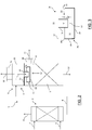
- the gaseous stream 14 withdrawn from the nozzle 15 of tower 3 is the result of the mixing of both CO2 streams 10 and 12. Hence this stream 14 contains the hydrogen and impurities of the first stream 10, leading to an overall concentration of hydrogen which is not negligible, typically around 0.5% molar.
Landscapes
- Chemical & Material Sciences (AREA)
- Chemical Kinetics & Catalysis (AREA)
- Engineering & Computer Science (AREA)
- Analytical Chemistry (AREA)
- General Chemical & Material Sciences (AREA)
- Oil, Petroleum & Natural Gas (AREA)
- Organic Chemistry (AREA)
- Inorganic Chemistry (AREA)
- Combustion & Propulsion (AREA)
- Gas Separation By Absorption (AREA)
- Treating Waste Gases (AREA)
- Hydrogen, Water And Hydrids (AREA)
- Carbon And Carbon Compounds (AREA)
Claims (6)
- Procédé de restructuration d'une section d'élimination de CO2 pour éliminer le dioxyde de carbone d'un gaz de synthèse contenant de l'hydrogène, dans lequel :ladite section d'élimination de CO2 (1) comprend une section d'absorption (2) dans laquelle le dioxyde de carbone est éliminé du gaz de synthèse (6) par absorption dans une solution absorbante (7), de façon à obtenir une solution riche en CO2 (8), etun rectificateur (3) pour la régénération de la solution riche en CO2 (8), comprenant une zone supérieure (4) dans laquelle ladite solution provenant de l'absorbeur est vaporisée par détente de façon à produire un premier flux gazeux (10) contenant du CO2 et une solution semi-pauvre partiellement régénérée (11), et une zone inférieure (5) servant de zone de rectification dans laquelle la solution semi-pauvre (11) est rectifiée de façon à produire un deuxième flux gazeux (12) contenant du CO2 et une solution régénérée pauvre (13),ledit deuxième flux gazeux (12) ayant une teneur en hydrogène qui est inférieure à la teneur en hydrogène dudit premier flux gazeux (10),le procédé de restructuration comprenant :la fourniture de moyens d'étanchéité (16) agencés pour isoler ledit deuxième flux gazeux (12) dudit premier flux gazeux (10) et pour exporter lesdits premier flux (10) et deuxième flux (12) séparément du rectificateur (3),dans lequel lesdits moyens d'étanchéité (16) comprennent des moyens de séparation (17) agencés pour séparer la zone supérieure (4) en une zone de vaporisation par détente (21) et une chambre (22), la solution riche en CO2 (8) est amenée dans ladite zone de vaporisation par détente dans laquelle la vaporisation par détente se produit, le premier flux gazeux (10) est collecté et la solution semi-pauvre (11) est générée ; ladite zone de vaporisation par détente (21) communique avec ladite chambre par l'intermédiaire d'au moins une ouverture (23) agencée pour amener la solution semi-pauvre (11) depuis la zone de vaporisation par détente vers la chambre ; ladite chambre (22) est en communication avec la zone de rectification (5) de sorte que le deuxième flux gazeux (12) est collecté dans ladite chambre et la solution semi-pauvre (11) s'écoule depuis la chambre (22) vers ladite zone de rectification (5),dans lequel lesdits moyens de séparation comprennent un déflecteur de séparation (17) qui délimite ladite zone de vaporisation par détente (21) et ladite chambre (22) dans la zone supérieure (4), la zone de vaporisation par détente (21) étant au-dessus dudit déflecteur et la chambre (22) étant en dessous dudit déflecteur, ledit déflecteur (17) comportant un conduit (19) se terminant par ladite au moins une ouverture (23) pour la communication entre la zone de vaporisation par détente et la chambre,dans lequel lesdits moyens d'étanchéité (16) sont agencés pour former un joint étanche aux gaz entre ladite zone de vaporisation par détente (21) et ladite zone de rectification (5), et ledit joint étanche aux gaz est produit par un niveau de liquide de la solution semi-pauvre (11) s'écoulant depuis la chambre (22) vers la zone de rectification (5),dans lequel les moyens d'étanchéité comprennent un distributeur (20) situé dans la chambre (22), faisant face à ladite au moins une ouverture (23) et configuré pour maintenir ladite au moins une ouverture en dessous dudit niveau de liquide (26) de la solution semi-pauvre, et ladite au moins une ouverture (23) étant située en dessous d'un bord (25a) d'une paroi latérale (25) dudit distributeur (20), de sorte que, pendant le fonctionnement, le niveau (26) de la solution semi-pauvre dans le distributeur est au-dessus de ladite au moins une ouverture.
- Procédé selon l'une quelconque des revendications précédentes, comprenant la fourniture d'une buse supplémentaire (28) agencée pour exporter ledit deuxième flux gazeux (12) depuis ladite chambre (22).
- Procédé selon l'une quelconque des revendications précédentes, dans lequel ledit premier flux gazeux (10) a une teneur en hydrogène qui est supérieure à 0,1 % et de préférence dans la plage de 1 à 4 %, et ledit deuxième flux gazeux (12) a une teneur en hydrogène qui n'est pas supérieure à 0,1 % et de préférence dans la plage de 0,03 à 0,07 %.
- Procédé selon l'une quelconque des revendications précédentes, dans lequel ledit deuxième flux gazeux (12) contient au moins 75 % du dioxyde de carbone précédemment contenu dans la solution riche en CO2 (8).
- Procédé selon l'une quelconque des revendications précédentes, dans lequel ledit premier flux gazeux (10) est utilisé pour la synthèse de méthanol et ledit deuxième flux gazeux (12) est utilisé pour la synthèse d'urée par réaction avec de l'ammoniac ou dans l'industrie alimentaire.
- Section d'élimination de CO2 (1) pour éliminer le dioxyde de carbone d'un gaz de synthèse contenant de l'hydrogène (6), comprenant :une section d'absorption (2) pour l'absorption de dioxyde de carbone dans une solution absorbante, de façon à obtenir une solution riche en CO2 (8), etun rectificateur (3) pour la régénération de ladite solution riche en CO2, comprenant une zone supérieure (4) dans laquelle ladite solution provenant de l'absorbeur est vaporisée par détente pour produire un premier flux gazeux contenant du CO2 (10) et une solution semi-pauvre partiellement régénérée (11), et une zone inférieure (5) agissant en tant que zone de rectification dans laquelle la solution semi-pauvre (11) est rectifiée pour produire un deuxième flux gazeux (12) contenant du CO2 et une solution régénérée pauvre (13),la section d'élimination de CO2 comprenant des moyens d'étanchéité (16) pour isoler ledit deuxième flux gazeux (12) dudit premier flux gazeux (10) et exporter lesdits premier flux et deuxième flux séparément du rectificateur dans lequel :lesdits moyens d'étanchéité (16) comprennent des moyens de séparation (17, 30) agencés pour séparer ladite zone supérieure (4) en une zone de vaporisation par détente (21, 32) et une chambre (22, 33),la solution riche en CO2 (8) est amenée dans ladite zone de vaporisation par détente dans laquelle la vaporisation par détente se produit, le premier flux gazeux (10) est collecté et la solution semi-pauvre (11) est générée ;ladite zone de vaporisation par détente (21) communique avec ladite chambre par l'intermédiaire d'au moins une ouverture (23) agencée pour amener la solution semi-pauvre (11) depuis la zone de vaporisation par détente vers la chambre ;ladite chambre (22) est en communication avec la zone de rectification (5) de sorte que le deuxième flux gazeux (12) est collecté dans ladite chambre et la solution semi-pauvre (11) s'écoule depuis la chambre (22) vers ladite zone de rectification (5),ladite section d'élimination de CO2 comprenant un déflecteur de séparation (17) qui délimite ladite zone de vaporisation par détente (21) et ladite chambre (22) dans la zone supérieure (4), la zone de vaporisation par détente (4) étant au-dessus dudit déflecteur et la chambre (22) étant en dessous dudit déflecteur, et ledit déflecteur (17) comporte un conduit (19) se terminant par ladite au moins une ouverture (23) pour la communication entre la zone de vaporisation par détente et la chambre,dans laquelle lesdits moyens d'étanchéité (16) sont agencés pour former un joint étanche aux gaz entre la zone de vaporisation par détente (21) et ladite zone de rectification (5), et ledit joint étanche aux gaz est produit par un niveau de liquide de la solution semi-pauvre (11) s'écoulant depuis la chambre (22) vers la zone de rectification (5),dans laquelle les moyens d'étanchéité comprennent un distributeur (20) de la solution semi-pauvre (11) situé dans la chambre (22), faisant face à ladite au moins une ouverture (23) et configuré pour maintenir ladite au moins une ouverture en dessous dudit niveau de liquide (26) de la solution semi-pauvre, et ladite au moins une ouverture (23) étant située en dessous d'un bord (25a) d'une paroi latérale (25) dudit distributeur (20), de sorte que, pendant le fonctionnement, le niveau (26) de la solution semi-pauvre dans le distributeur est au-dessus de ladite au moins une ouverture.
Applications Claiming Priority (3)
| Application Number | Priority Date | Filing Date | Title |
|---|---|---|---|
| EP15181571 | 2015-08-19 | ||
| PCT/EP2016/068863 WO2017029145A1 (fr) | 2015-08-19 | 2016-08-08 | Procédé pour restructurer une section d'élimination de co2 pour la purification d'un gaz contenant de l'hydrogène |
| EP16753315.7A EP3337593B1 (fr) | 2015-08-19 | 2016-08-08 | Procédé de transformation d'une section d'élimination de co2 pour la purification d'un gaz contenant de l'hydrogène |
Related Parent Applications (2)
| Application Number | Title | Priority Date | Filing Date |
|---|---|---|---|
| EP16753315.7A Division-Into EP3337593B1 (fr) | 2015-08-19 | 2016-08-08 | Procédé de transformation d'une section d'élimination de co2 pour la purification d'un gaz contenant de l'hydrogène |
| EP16753315.7A Division EP3337593B1 (fr) | 2015-08-19 | 2016-08-08 | Procédé de transformation d'une section d'élimination de co2 pour la purification d'un gaz contenant de l'hydrogène |
Publications (2)
| Publication Number | Publication Date |
|---|---|
| EP3552687A1 EP3552687A1 (fr) | 2019-10-16 |
| EP3552687B1 true EP3552687B1 (fr) | 2020-11-04 |
Family
ID=54012005
Family Applications (2)
| Application Number | Title | Priority Date | Filing Date |
|---|---|---|---|
| EP19167761.6A Active EP3552687B1 (fr) | 2015-08-19 | 2016-08-08 | Procédé de transformation d'une section d'élimination de co2 pour la purification d'un gaz contenant de l'hydrogène |
| EP16753315.7A Active EP3337593B1 (fr) | 2015-08-19 | 2016-08-08 | Procédé de transformation d'une section d'élimination de co2 pour la purification d'un gaz contenant de l'hydrogène |
Family Applications After (1)
| Application Number | Title | Priority Date | Filing Date |
|---|---|---|---|
| EP16753315.7A Active EP3337593B1 (fr) | 2015-08-19 | 2016-08-08 | Procédé de transformation d'une section d'élimination de co2 pour la purification d'un gaz contenant de l'hydrogène |
Country Status (14)
| Country | Link |
|---|---|
| US (1) | US11154810B2 (fr) |
| EP (2) | EP3552687B1 (fr) |
| CN (1) | CN108012532B (fr) |
| AU (1) | AU2016309890A1 (fr) |
| BR (1) | BR112018003160B1 (fr) |
| CA (1) | CA2994052C (fr) |
| CL (1) | CL2018000280A1 (fr) |
| EA (1) | EA037684B1 (fr) |
| MX (1) | MX2018001573A (fr) |
| MY (1) | MY176501A (fr) |
| RU (1) | RU2721114C2 (fr) |
| SA (1) | SA518390940B1 (fr) |
| UA (1) | UA124618C2 (fr) |
| WO (1) | WO2017029145A1 (fr) |
Families Citing this family (1)
| Publication number | Priority date | Publication date | Assignee | Title |
|---|---|---|---|---|
| GB2622087A (en) | 2022-09-02 | 2024-03-06 | Johnson Matthey Plc | Carbon dioxide removal unit |
Family Cites Families (14)
| Publication number | Priority date | Publication date | Assignee | Title |
|---|---|---|---|---|
| FR2474887A1 (fr) * | 1980-02-05 | 1981-08-07 | Isman Marcel | Ensemble de traitement de lavage de gaz |
| CH680908A5 (en) * | 1990-08-27 | 1992-12-15 | Sulzer Ag | Multistage pptn. and stripping column for liq. suspensions - has in at least one stage, a rapid dispersal agitator in lower region of funnel bottom |
| US5281254A (en) | 1992-05-22 | 1994-01-25 | United Technologies Corporation | Continuous carbon dioxide and water removal system |
| FR2807505B1 (fr) * | 2000-04-07 | 2002-06-14 | Air Liquide | Distributeur liquide-gaz pour colonne d'echange de matiere et/ou de chaleur, et colonne utilisant un tel distributeur |
| US7192468B2 (en) * | 2002-04-15 | 2007-03-20 | Fluor Technologies Corporation | Configurations and method for improved gas removal |
| CN100337722C (zh) * | 2002-04-15 | 2007-09-19 | 弗劳尔公司 | 改进酸性气体脱除的装置和方法 |
| US6929680B2 (en) * | 2003-09-26 | 2005-08-16 | Consortium Services Management Group, Inc. | CO2 separator method and apparatus |
| DE102008025971A1 (de) | 2008-05-30 | 2009-12-03 | Dge Dr.-Ing. Günther Engineering Gmbh | Verfahren und Anlage zur Reinigung von Biogas zur Gewinnung von Methan |
| JP5134578B2 (ja) * | 2009-04-03 | 2013-01-30 | 三菱重工業株式会社 | Co2回収装置及びその方法 |
| US8460436B2 (en) | 2009-11-24 | 2013-06-11 | Alstom Technology Ltd | Advanced intercooling and recycling in CO2 absorption |
| CN101857226A (zh) * | 2010-06-28 | 2010-10-13 | 天津市泰源工业气体有限公司 | 碳酸丙烯酯生产二氧化碳的技术 |
| JP5972696B2 (ja) * | 2012-07-20 | 2016-08-17 | 三菱重工業株式会社 | Co2回収システム |
| RU2526455C2 (ru) * | 2012-12-06 | 2014-08-20 | Общество с ограниченной ответственностью "Научно Исследовательский Проектный Институт нефти и газа "Петон" | Способ очистки отходящих газов от сероводорода |
| DE102013015849A1 (de) * | 2013-09-24 | 2015-03-26 | Linde Aktiengesellschaft | Verfahren und Vorrichtung zur Sauergaswäsche |
-
2016
- 2016-08-08 EP EP19167761.6A patent/EP3552687B1/fr active Active
- 2016-08-08 MY MYPI2018700597A patent/MY176501A/en unknown
- 2016-08-08 RU RU2018109429A patent/RU2721114C2/ru active
- 2016-08-08 MX MX2018001573A patent/MX2018001573A/es unknown
- 2016-08-08 AU AU2016309890A patent/AU2016309890A1/en not_active Abandoned
- 2016-08-08 EA EA201990111A patent/EA037684B1/ru unknown
- 2016-08-08 WO PCT/EP2016/068863 patent/WO2017029145A1/fr not_active Ceased
- 2016-08-08 EP EP16753315.7A patent/EP3337593B1/fr active Active
- 2016-08-08 UA UAA201802686A patent/UA124618C2/uk unknown
- 2016-08-08 BR BR112018003160-7A patent/BR112018003160B1/pt active IP Right Grant
- 2016-08-08 US US15/753,499 patent/US11154810B2/en active Active
- 2016-08-08 CA CA2994052A patent/CA2994052C/fr active Active
- 2016-08-08 CN CN201680047258.4A patent/CN108012532B/zh active Active
-
2018
- 2018-01-31 CL CL2018000280A patent/CL2018000280A1/es unknown
- 2018-02-15 SA SA518390940A patent/SA518390940B1/ar unknown
Non-Patent Citations (1)
| Title |
|---|
| None * |
Also Published As
| Publication number | Publication date |
|---|---|
| WO2017029145A1 (fr) | 2017-02-23 |
| US11154810B2 (en) | 2021-10-26 |
| CN108012532B (zh) | 2021-08-20 |
| CL2018000280A1 (es) | 2018-06-29 |
| CA2994052C (fr) | 2023-03-07 |
| EA037684B1 (ru) | 2021-04-29 |
| SA518390940B1 (ar) | 2022-11-09 |
| BR112018003160A2 (pt) | 2018-10-09 |
| EP3337593B1 (fr) | 2019-06-05 |
| BR112018003160B1 (pt) | 2022-09-27 |
| RU2018109429A (ru) | 2019-09-19 |
| US20180243683A1 (en) | 2018-08-30 |
| EP3337593A1 (fr) | 2018-06-27 |
| EA201990111A1 (ru) | 2019-05-31 |
| CA2994052A1 (fr) | 2017-02-23 |
| UA124618C2 (uk) | 2021-10-20 |
| EP3552687A1 (fr) | 2019-10-16 |
| RU2721114C2 (ru) | 2020-05-15 |
| MX2018001573A (es) | 2018-05-02 |
| CN108012532A (zh) | 2018-05-08 |
| AU2016309890A1 (en) | 2018-02-22 |
| MY176501A (en) | 2020-08-12 |
| RU2018109429A3 (fr) | 2019-10-11 |
Similar Documents
| Publication | Publication Date | Title |
|---|---|---|
| EP0964829B1 (fr) | Elimination des gaz acides dans un systeme de generation d'energie par gazeification avec production d'hydrogene | |
| US4999031A (en) | Removing CO2 and, if necessary, H2 S from gases | |
| US7083662B2 (en) | Generation of elevated pressure gas mixtures by absorption and stripping | |
| US7183326B2 (en) | Installation and method for producing and disaggregating synthesis gases from natural gas | |
| EP2617708B1 (fr) | Procédé de formation d'urée par intégration d'un procédé de production d'ammoniac dans un procédé de production d'urée et système associé | |
| EP2070905B1 (fr) | Procédé pour la préparation d'éther de diméthyle pur | |
| US3640052A (en) | Process for removing carbon dioxide in a combined system for producing ammonia and urea | |
| EP3552687B1 (fr) | Procédé de transformation d'une section d'élimination de co2 pour la purification d'un gaz contenant de l'hydrogène | |
| US11634325B2 (en) | Absorber column and process for cleaning crude synthesis gas | |
| AU2014211773A1 (en) | Method and device for generating fuel for a gas turbine | |
| US20190152777A1 (en) | A method for the reduction of methanol emission from an ammonia plant | |
| US10874977B2 (en) | Process for removal of acidic gas constituents from synthesis gas and apparatus for producing recycle gas | |
| US9611202B2 (en) | Process for the preparation of dimethyl ether | |
| CN107149854A (zh) | 在气体洗涤中生产塔的布置方式 | |
| EP2637767B1 (fr) | Flux de gaz de transformation résultant d'un procédé de carbonylation | |
| RU2426717C2 (ru) | Способ и установка для получения метанола | |
| Ma et al. | Process simulation for electronic-grade methanethiol synthesis via H2S recovery from Rectisol Tail Gas | |
| WO2026017964A1 (fr) | Procédé d'extraction de méthanol | |
| NZ760481A (en) | Method for the preparation of ammonia synthesis gas |
Legal Events
| Date | Code | Title | Description |
|---|---|---|---|
| PUAI | Public reference made under article 153(3) epc to a published international application that has entered the european phase |
Free format text: ORIGINAL CODE: 0009012 |
|
| STAA | Information on the status of an ep patent application or granted ep patent |
Free format text: STATUS: THE APPLICATION HAS BEEN PUBLISHED |
|
| AC | Divisional application: reference to earlier application |
Ref document number: 3337593 Country of ref document: EP Kind code of ref document: P |
|
| AK | Designated contracting states |
Kind code of ref document: A1 Designated state(s): AL AT BE BG CH CY CZ DE DK EE ES FI FR GB GR HR HU IE IS IT LI LT LU LV MC MK MT NL NO PL PT RO RS SE SI SK SM TR |
|
| STAA | Information on the status of an ep patent application or granted ep patent |
Free format text: STATUS: REQUEST FOR EXAMINATION WAS MADE |
|
| 17P | Request for examination filed |
Effective date: 20200414 |
|
| RBV | Designated contracting states (corrected) |
Designated state(s): AL AT BE BG CH CY CZ DE DK EE ES FI FR GB GR HR HU IE IS IT LI LT LU LV MC MK MT NL NO PL PT RO RS SE SI SK SM TR |
|
| GRAP | Despatch of communication of intention to grant a patent |
Free format text: ORIGINAL CODE: EPIDOSNIGR1 |
|
| STAA | Information on the status of an ep patent application or granted ep patent |
Free format text: STATUS: GRANT OF PATENT IS INTENDED |
|
| INTG | Intention to grant announced |
Effective date: 20200720 |
|
| GRAS | Grant fee paid |
Free format text: ORIGINAL CODE: EPIDOSNIGR3 |
|
| GRAA | (expected) grant |
Free format text: ORIGINAL CODE: 0009210 |
|
| STAA | Information on the status of an ep patent application or granted ep patent |
Free format text: STATUS: THE PATENT HAS BEEN GRANTED |
|
| AC | Divisional application: reference to earlier application |
Ref document number: 3337593 Country of ref document: EP Kind code of ref document: P |
|
| AK | Designated contracting states |
Kind code of ref document: B1 Designated state(s): AL AT BE BG CH CY CZ DE DK EE ES FI FR GB GR HR HU IE IS IT LI LT LU LV MC MK MT NL NO PL PT RO RS SE SI SK SM TR |
|
| REG | Reference to a national code |
Ref country code: GB Ref legal event code: FG4D |
|
| REG | Reference to a national code |
Ref country code: CH Ref legal event code: EP |
|
| REG | Reference to a national code |
Ref country code: AT Ref legal event code: REF Ref document number: 1330075 Country of ref document: AT Kind code of ref document: T Effective date: 20201115 |
|
| REG | Reference to a national code |
Ref country code: IE Ref legal event code: FG4D |
|
| REG | Reference to a national code |
Ref country code: DE Ref legal event code: R096 Ref document number: 602016047522 Country of ref document: DE |
|
| REG | Reference to a national code |
Ref country code: NL Ref legal event code: MP Effective date: 20201104 |
|
| REG | Reference to a national code |
Ref country code: AT Ref legal event code: MK05 Ref document number: 1330075 Country of ref document: AT Kind code of ref document: T Effective date: 20201104 |
|
| PG25 | Lapsed in a contracting state [announced via postgrant information from national office to epo] |
Ref country code: FI Free format text: LAPSE BECAUSE OF FAILURE TO SUBMIT A TRANSLATION OF THE DESCRIPTION OR TO PAY THE FEE WITHIN THE PRESCRIBED TIME-LIMIT Effective date: 20201104 Ref country code: PT Free format text: LAPSE BECAUSE OF FAILURE TO SUBMIT A TRANSLATION OF THE DESCRIPTION OR TO PAY THE FEE WITHIN THE PRESCRIBED TIME-LIMIT Effective date: 20210304 Ref country code: RS Free format text: LAPSE BECAUSE OF FAILURE TO SUBMIT A TRANSLATION OF THE DESCRIPTION OR TO PAY THE FEE WITHIN THE PRESCRIBED TIME-LIMIT Effective date: 20201104 Ref country code: GR Free format text: LAPSE BECAUSE OF FAILURE TO SUBMIT A TRANSLATION OF THE DESCRIPTION OR TO PAY THE FEE WITHIN THE PRESCRIBED TIME-LIMIT Effective date: 20210205 Ref country code: NO Free format text: LAPSE BECAUSE OF FAILURE TO SUBMIT A TRANSLATION OF THE DESCRIPTION OR TO PAY THE FEE WITHIN THE PRESCRIBED TIME-LIMIT Effective date: 20210204 |
|
| PG25 | Lapsed in a contracting state [announced via postgrant information from national office to epo] |
Ref country code: ES Free format text: LAPSE BECAUSE OF FAILURE TO SUBMIT A TRANSLATION OF THE DESCRIPTION OR TO PAY THE FEE WITHIN THE PRESCRIBED TIME-LIMIT Effective date: 20201104 Ref country code: AT Free format text: LAPSE BECAUSE OF FAILURE TO SUBMIT A TRANSLATION OF THE DESCRIPTION OR TO PAY THE FEE WITHIN THE PRESCRIBED TIME-LIMIT Effective date: 20201104 Ref country code: BG Free format text: LAPSE BECAUSE OF FAILURE TO SUBMIT A TRANSLATION OF THE DESCRIPTION OR TO PAY THE FEE WITHIN THE PRESCRIBED TIME-LIMIT Effective date: 20210204 Ref country code: SE Free format text: LAPSE BECAUSE OF FAILURE TO SUBMIT A TRANSLATION OF THE DESCRIPTION OR TO PAY THE FEE WITHIN THE PRESCRIBED TIME-LIMIT Effective date: 20201104 Ref country code: LV Free format text: LAPSE BECAUSE OF FAILURE TO SUBMIT A TRANSLATION OF THE DESCRIPTION OR TO PAY THE FEE WITHIN THE PRESCRIBED TIME-LIMIT Effective date: 20201104 Ref country code: PL Free format text: LAPSE BECAUSE OF FAILURE TO SUBMIT A TRANSLATION OF THE DESCRIPTION OR TO PAY THE FEE WITHIN THE PRESCRIBED TIME-LIMIT Effective date: 20201104 Ref country code: IS Free format text: LAPSE BECAUSE OF FAILURE TO SUBMIT A TRANSLATION OF THE DESCRIPTION OR TO PAY THE FEE WITHIN THE PRESCRIBED TIME-LIMIT Effective date: 20210304 |
|
| REG | Reference to a national code |
Ref country code: LT Ref legal event code: MG9D |
|
| PG25 | Lapsed in a contracting state [announced via postgrant information from national office to epo] |
Ref country code: HR Free format text: LAPSE BECAUSE OF FAILURE TO SUBMIT A TRANSLATION OF THE DESCRIPTION OR TO PAY THE FEE WITHIN THE PRESCRIBED TIME-LIMIT Effective date: 20201104 |
|
| PG25 | Lapsed in a contracting state [announced via postgrant information from national office to epo] |
Ref country code: RO Free format text: LAPSE BECAUSE OF FAILURE TO SUBMIT A TRANSLATION OF THE DESCRIPTION OR TO PAY THE FEE WITHIN THE PRESCRIBED TIME-LIMIT Effective date: 20201104 Ref country code: LT Free format text: LAPSE BECAUSE OF FAILURE TO SUBMIT A TRANSLATION OF THE DESCRIPTION OR TO PAY THE FEE WITHIN THE PRESCRIBED TIME-LIMIT Effective date: 20201104 Ref country code: SM Free format text: LAPSE BECAUSE OF FAILURE TO SUBMIT A TRANSLATION OF THE DESCRIPTION OR TO PAY THE FEE WITHIN THE PRESCRIBED TIME-LIMIT Effective date: 20201104 Ref country code: SK Free format text: LAPSE BECAUSE OF FAILURE TO SUBMIT A TRANSLATION OF THE DESCRIPTION OR TO PAY THE FEE WITHIN THE PRESCRIBED TIME-LIMIT Effective date: 20201104 Ref country code: EE Free format text: LAPSE BECAUSE OF FAILURE TO SUBMIT A TRANSLATION OF THE DESCRIPTION OR TO PAY THE FEE WITHIN THE PRESCRIBED TIME-LIMIT Effective date: 20201104 Ref country code: CZ Free format text: LAPSE BECAUSE OF FAILURE TO SUBMIT A TRANSLATION OF THE DESCRIPTION OR TO PAY THE FEE WITHIN THE PRESCRIBED TIME-LIMIT Effective date: 20201104 |
|
| REG | Reference to a national code |
Ref country code: DE Ref legal event code: R097 Ref document number: 602016047522 Country of ref document: DE |
|
| PG25 | Lapsed in a contracting state [announced via postgrant information from national office to epo] |
Ref country code: DK Free format text: LAPSE BECAUSE OF FAILURE TO SUBMIT A TRANSLATION OF THE DESCRIPTION OR TO PAY THE FEE WITHIN THE PRESCRIBED TIME-LIMIT Effective date: 20201104 |
|
| PLBE | No opposition filed within time limit |
Free format text: ORIGINAL CODE: 0009261 |
|
| STAA | Information on the status of an ep patent application or granted ep patent |
Free format text: STATUS: NO OPPOSITION FILED WITHIN TIME LIMIT |
|
| 26N | No opposition filed |
Effective date: 20210805 |
|
| PG25 | Lapsed in a contracting state [announced via postgrant information from national office to epo] |
Ref country code: IT Free format text: LAPSE BECAUSE OF FAILURE TO SUBMIT A TRANSLATION OF THE DESCRIPTION OR TO PAY THE FEE WITHIN THE PRESCRIBED TIME-LIMIT Effective date: 20201104 Ref country code: NL Free format text: LAPSE BECAUSE OF FAILURE TO SUBMIT A TRANSLATION OF THE DESCRIPTION OR TO PAY THE FEE WITHIN THE PRESCRIBED TIME-LIMIT Effective date: 20201104 Ref country code: AL Free format text: LAPSE BECAUSE OF FAILURE TO SUBMIT A TRANSLATION OF THE DESCRIPTION OR TO PAY THE FEE WITHIN THE PRESCRIBED TIME-LIMIT Effective date: 20201104 |
|
| PG25 | Lapsed in a contracting state [announced via postgrant information from national office to epo] |
Ref country code: SI Free format text: LAPSE BECAUSE OF FAILURE TO SUBMIT A TRANSLATION OF THE DESCRIPTION OR TO PAY THE FEE WITHIN THE PRESCRIBED TIME-LIMIT Effective date: 20201104 |
|
| REG | Reference to a national code |
Ref country code: CH Ref legal event code: PL |
|
| PG25 | Lapsed in a contracting state [announced via postgrant information from national office to epo] |
Ref country code: MC Free format text: LAPSE BECAUSE OF FAILURE TO SUBMIT A TRANSLATION OF THE DESCRIPTION OR TO PAY THE FEE WITHIN THE PRESCRIBED TIME-LIMIT Effective date: 20201104 |
|
| REG | Reference to a national code |
Ref country code: BE Ref legal event code: MM Effective date: 20210831 |
|
| PG25 | Lapsed in a contracting state [announced via postgrant information from national office to epo] |
Ref country code: LI Free format text: LAPSE BECAUSE OF NON-PAYMENT OF DUE FEES Effective date: 20210831 Ref country code: CH Free format text: LAPSE BECAUSE OF NON-PAYMENT OF DUE FEES Effective date: 20210831 |
|
| PG25 | Lapsed in a contracting state [announced via postgrant information from national office to epo] |
Ref country code: IS Free format text: LAPSE BECAUSE OF FAILURE TO SUBMIT A TRANSLATION OF THE DESCRIPTION OR TO PAY THE FEE WITHIN THE PRESCRIBED TIME-LIMIT Effective date: 20210304 Ref country code: LU Free format text: LAPSE BECAUSE OF NON-PAYMENT OF DUE FEES Effective date: 20210808 |
|
| PG25 | Lapsed in a contracting state [announced via postgrant information from national office to epo] |
Ref country code: IE Free format text: LAPSE BECAUSE OF NON-PAYMENT OF DUE FEES Effective date: 20210808 Ref country code: BE Free format text: LAPSE BECAUSE OF NON-PAYMENT OF DUE FEES Effective date: 20210831 |
|
| PG25 | Lapsed in a contracting state [announced via postgrant information from national office to epo] |
Ref country code: CY Free format text: LAPSE BECAUSE OF FAILURE TO SUBMIT A TRANSLATION OF THE DESCRIPTION OR TO PAY THE FEE WITHIN THE PRESCRIBED TIME-LIMIT Effective date: 20201104 |
|
| P01 | Opt-out of the competence of the unified patent court (upc) registered |
Effective date: 20230527 |
|
| PG25 | Lapsed in a contracting state [announced via postgrant information from national office to epo] |
Ref country code: HU Free format text: LAPSE BECAUSE OF FAILURE TO SUBMIT A TRANSLATION OF THE DESCRIPTION OR TO PAY THE FEE WITHIN THE PRESCRIBED TIME-LIMIT; INVALID AB INITIO Effective date: 20160808 |
|
| PG25 | Lapsed in a contracting state [announced via postgrant information from national office to epo] |
Ref country code: MK Free format text: LAPSE BECAUSE OF FAILURE TO SUBMIT A TRANSLATION OF THE DESCRIPTION OR TO PAY THE FEE WITHIN THE PRESCRIBED TIME-LIMIT Effective date: 20201104 |
|
| PG25 | Lapsed in a contracting state [announced via postgrant information from national office to epo] |
Ref country code: MT Free format text: LAPSE BECAUSE OF FAILURE TO SUBMIT A TRANSLATION OF THE DESCRIPTION OR TO PAY THE FEE WITHIN THE PRESCRIBED TIME-LIMIT Effective date: 20201104 |
|
| PGFP | Annual fee paid to national office [announced via postgrant information from national office to epo] |
Ref country code: DE Payment date: 20250724 Year of fee payment: 10 |
|
| PGFP | Annual fee paid to national office [announced via postgrant information from national office to epo] |
Ref country code: GB Payment date: 20250724 Year of fee payment: 10 |
|
| PGFP | Annual fee paid to national office [announced via postgrant information from national office to epo] |
Ref country code: FR Payment date: 20250725 Year of fee payment: 10 |
|
| PG25 | Lapsed in a contracting state [announced via postgrant information from national office to epo] |
Ref country code: TR Free format text: LAPSE BECAUSE OF FAILURE TO SUBMIT A TRANSLATION OF THE DESCRIPTION OR TO PAY THE FEE WITHIN THE PRESCRIBED TIME-LIMIT Effective date: 20201104 |