EP3552680B1 - Appareil de traitement d'eau comprenant un module de filtre - Google Patents
Appareil de traitement d'eau comprenant un module de filtre Download PDFInfo
- Publication number
- EP3552680B1 EP3552680B1 EP17878460.9A EP17878460A EP3552680B1 EP 3552680 B1 EP3552680 B1 EP 3552680B1 EP 17878460 A EP17878460 A EP 17878460A EP 3552680 B1 EP3552680 B1 EP 3552680B1
- Authority
- EP
- European Patent Office
- Prior art keywords
- water
- activated carbon
- carbon fiber
- filter
- treatment apparatus
- Prior art date
- Legal status (The legal status is an assumption and is not a legal conclusion. Google has not performed a legal analysis and makes no representation as to the accuracy of the status listed.)
- Active
Links
- XLYOFNOQVPJJNP-UHFFFAOYSA-N water Substances O XLYOFNOQVPJJNP-UHFFFAOYSA-N 0.000 title claims description 332
- VNWKTOKETHGBQD-UHFFFAOYSA-N methane Chemical class C VNWKTOKETHGBQD-UHFFFAOYSA-N 0.000 claims description 227
- OKTJSMMVPCPJKN-UHFFFAOYSA-N Carbon Chemical compound [C] OKTJSMMVPCPJKN-UHFFFAOYSA-N 0.000 claims description 40
- 229910052799 carbon Inorganic materials 0.000 claims description 30
- 239000008213 purified water Substances 0.000 claims description 19
- 239000012528 membrane Substances 0.000 claims description 16
- 125000006850 spacer group Chemical group 0.000 claims description 13
- 239000004744 fabric Substances 0.000 claims description 7
- JEGUKCSWCFPDGT-UHFFFAOYSA-N h2o hydrate Chemical compound O.O JEGUKCSWCFPDGT-UHFFFAOYSA-N 0.000 claims description 2
- 238000007599 discharging Methods 0.000 claims 1
- 150000002500 ions Chemical class 0.000 description 51
- 238000000034 method Methods 0.000 description 19
- 238000000746 purification Methods 0.000 description 17
- 239000000498 cooling water Substances 0.000 description 10
- 239000000463 material Substances 0.000 description 10
- 239000003507 refrigerant Substances 0.000 description 10
- 239000003014 ion exchange membrane Substances 0.000 description 9
- 238000001179 sorption measurement Methods 0.000 description 7
- 238000002242 deionisation method Methods 0.000 description 6
- 230000035699 permeability Effects 0.000 description 6
- 241000894006 Bacteria Species 0.000 description 5
- 241000700605 Viruses Species 0.000 description 5
- 150000002894 organic compounds Chemical class 0.000 description 5
- 239000007787 solid Substances 0.000 description 5
- 229920000049 Carbon (fiber) Polymers 0.000 description 4
- 238000010521 absorption reaction Methods 0.000 description 4
- 239000012530 fluid Substances 0.000 description 4
- 239000003990 capacitor Substances 0.000 description 3
- 238000009296 electrodeionization Methods 0.000 description 3
- 238000001914 filtration Methods 0.000 description 3
- 229910001385 heavy metal Inorganic materials 0.000 description 3
- 239000012071 phase Substances 0.000 description 3
- 239000004917 carbon fiber Substances 0.000 description 2
- 238000004140 cleaning Methods 0.000 description 2
- 239000000356 contaminant Substances 0.000 description 2
- 230000003247 decreasing effect Effects 0.000 description 2
- 230000000694 effects Effects 0.000 description 2
- 239000000284 extract Substances 0.000 description 2
- 238000009434 installation Methods 0.000 description 2
- 244000005700 microbiome Species 0.000 description 2
- 239000013618 particulate matter Substances 0.000 description 2
- 230000001681 protective effect Effects 0.000 description 2
- 238000005406 washing Methods 0.000 description 2
- DGAQECJNVWCQMB-PUAWFVPOSA-M Ilexoside XXIX Chemical compound C[C@@H]1CC[C@@]2(CC[C@@]3(C(=CC[C@H]4[C@]3(CC[C@@H]5[C@@]4(CC[C@@H](C5(C)C)OS(=O)(=O)[O-])C)C)[C@@H]2[C@]1(C)O)C)C(=O)O[C@H]6[C@@H]([C@H]([C@@H]([C@H](O6)CO)O)O)O.[Na+] DGAQECJNVWCQMB-PUAWFVPOSA-M 0.000 description 1
- 239000004677 Nylon Substances 0.000 description 1
- 239000011230 binding agent Substances 0.000 description 1
- 229910052793 cadmium Inorganic materials 0.000 description 1
- BDOSMKKIYDKNTQ-UHFFFAOYSA-N cadmium atom Chemical compound [Cd] BDOSMKKIYDKNTQ-UHFFFAOYSA-N 0.000 description 1
- 150000001875 compounds Chemical class 0.000 description 1
- 239000004020 conductor Substances 0.000 description 1
- 238000009792 diffusion process Methods 0.000 description 1
- 235000020188 drinking water Nutrition 0.000 description 1
- 239000003651 drinking water Substances 0.000 description 1
- 239000000835 fiber Substances 0.000 description 1
- 239000011888 foil Substances 0.000 description 1
- 229910002804 graphite Inorganic materials 0.000 description 1
- 239000010439 graphite Substances 0.000 description 1
- -1 heavy metals Chemical class 0.000 description 1
- 239000012212 insulator Substances 0.000 description 1
- 235000014413 iron hydroxide Nutrition 0.000 description 1
- NCNCGGDMXMBVIA-UHFFFAOYSA-L iron(ii) hydroxide Chemical compound [OH-].[OH-].[Fe+2] NCNCGGDMXMBVIA-UHFFFAOYSA-L 0.000 description 1
- 239000007791 liquid phase Substances 0.000 description 1
- 229920001778 nylon Polymers 0.000 description 1
- 239000002245 particle Substances 0.000 description 1
- 229920005596 polymer binder Polymers 0.000 description 1
- 239000002491 polymer binding agent Substances 0.000 description 1
- 230000001172 regenerating effect Effects 0.000 description 1
- 230000008929 regeneration Effects 0.000 description 1
- 238000011069 regeneration method Methods 0.000 description 1
- 229910052708 sodium Inorganic materials 0.000 description 1
- 239000011734 sodium Substances 0.000 description 1
- 239000008234 soft water Substances 0.000 description 1
- 239000000126 substance Substances 0.000 description 1
- 239000008399 tap water Substances 0.000 description 1
- 235000020679 tap water Nutrition 0.000 description 1
Images


Classifications
-
- C—CHEMISTRY; METALLURGY
- C02—TREATMENT OF WATER, WASTE WATER, SEWAGE, OR SLUDGE
- C02F—TREATMENT OF WATER, WASTE WATER, SEWAGE, OR SLUDGE
- C02F1/00—Treatment of water, waste water, or sewage
- C02F1/46—Treatment of water, waste water, or sewage by electrochemical methods
- C02F1/469—Treatment of water, waste water, or sewage by electrochemical methods by electrochemical separation, e.g. by electro-osmosis, electrodialysis, electrophoresis
- C02F1/4693—Treatment of water, waste water, or sewage by electrochemical methods by electrochemical separation, e.g. by electro-osmosis, electrodialysis, electrophoresis electrodialysis
- C02F1/4695—Treatment of water, waste water, or sewage by electrochemical methods by electrochemical separation, e.g. by electro-osmosis, electrodialysis, electrophoresis electrodialysis electrodeionisation
-
- B—PERFORMING OPERATIONS; TRANSPORTING
- B01—PHYSICAL OR CHEMICAL PROCESSES OR APPARATUS IN GENERAL
- B01D—SEPARATION
- B01D15/00—Separating processes involving the treatment of liquids with solid sorbents; Apparatus therefor
- B01D15/08—Selective adsorption, e.g. chromatography
- B01D15/10—Selective adsorption, e.g. chromatography characterised by constructional or operational features
- B01D15/20—Selective adsorption, e.g. chromatography characterised by constructional or operational features relating to the conditioning of the sorbent material
- B01D15/203—Equilibration or regeneration
-
- B—PERFORMING OPERATIONS; TRANSPORTING
- B01—PHYSICAL OR CHEMICAL PROCESSES OR APPARATUS IN GENERAL
- B01D—SEPARATION
- B01D15/00—Separating processes involving the treatment of liquids with solid sorbents; Apparatus therefor
- B01D15/08—Selective adsorption, e.g. chromatography
- B01D15/26—Selective adsorption, e.g. chromatography characterised by the separation mechanism
- B01D15/38—Selective adsorption, e.g. chromatography characterised by the separation mechanism involving specific interaction not covered by one or more of groups B01D15/265 - B01D15/36
- B01D15/3861—Selective adsorption, e.g. chromatography characterised by the separation mechanism involving specific interaction not covered by one or more of groups B01D15/265 - B01D15/36 using an external stimulus
- B01D15/3885—Using electrical or magnetic means
-
- B—PERFORMING OPERATIONS; TRANSPORTING
- B01—PHYSICAL OR CHEMICAL PROCESSES OR APPARATUS IN GENERAL
- B01D—SEPARATION
- B01D35/00—Filtering devices having features not specifically covered by groups B01D24/00 - B01D33/00, or for applications not specifically covered by groups B01D24/00 - B01D33/00; Auxiliary devices for filtration; Filter housing constructions
- B01D35/06—Filters making use of electricity or magnetism
-
- B—PERFORMING OPERATIONS; TRANSPORTING
- B01—PHYSICAL OR CHEMICAL PROCESSES OR APPARATUS IN GENERAL
- B01D—SEPARATION
- B01D35/00—Filtering devices having features not specifically covered by groups B01D24/00 - B01D33/00, or for applications not specifically covered by groups B01D24/00 - B01D33/00; Auxiliary devices for filtration; Filter housing constructions
- B01D35/16—Cleaning-out devices, e.g. for removing the cake from the filter casing or for evacuating the last remnants of liquid
-
- B—PERFORMING OPERATIONS; TRANSPORTING
- B01—PHYSICAL OR CHEMICAL PROCESSES OR APPARATUS IN GENERAL
- B01D—SEPARATION
- B01D35/00—Filtering devices having features not specifically covered by groups B01D24/00 - B01D33/00, or for applications not specifically covered by groups B01D24/00 - B01D33/00; Auxiliary devices for filtration; Filter housing constructions
- B01D35/30—Filter housing constructions
-
- B—PERFORMING OPERATIONS; TRANSPORTING
- B01—PHYSICAL OR CHEMICAL PROCESSES OR APPARATUS IN GENERAL
- B01D—SEPARATION
- B01D39/00—Filtering material for liquid or gaseous fluids
- B01D39/14—Other self-supporting filtering material ; Other filtering material
- B01D39/20—Other self-supporting filtering material ; Other filtering material of inorganic material, e.g. asbestos paper, metallic filtering material of non-woven wires
- B01D39/2055—Carbonaceous material
- B01D39/2058—Carbonaceous material the material being particulate
- B01D39/2062—Bonded, e.g. activated carbon blocks
-
- B—PERFORMING OPERATIONS; TRANSPORTING
- B01—PHYSICAL OR CHEMICAL PROCESSES OR APPARATUS IN GENERAL
- B01D—SEPARATION
- B01D61/00—Processes of separation using semi-permeable membranes, e.g. dialysis, osmosis or ultrafiltration; Apparatus, accessories or auxiliary operations specially adapted therefor
- B01D61/14—Ultrafiltration; Microfiltration
- B01D61/145—Ultrafiltration
-
- C—CHEMISTRY; METALLURGY
- C02—TREATMENT OF WATER, WASTE WATER, SEWAGE, OR SLUDGE
- C02F—TREATMENT OF WATER, WASTE WATER, SEWAGE, OR SLUDGE
- C02F1/00—Treatment of water, waste water, or sewage
- C02F1/28—Treatment of water, waste water, or sewage by sorption
- C02F1/283—Treatment of water, waste water, or sewage by sorption using coal, charred products, or inorganic mixtures containing them
-
- C—CHEMISTRY; METALLURGY
- C02—TREATMENT OF WATER, WASTE WATER, SEWAGE, OR SLUDGE
- C02F—TREATMENT OF WATER, WASTE WATER, SEWAGE, OR SLUDGE
- C02F1/00—Treatment of water, waste water, or sewage
- C02F1/44—Treatment of water, waste water, or sewage by dialysis, osmosis or reverse osmosis
- C02F1/444—Treatment of water, waste water, or sewage by dialysis, osmosis or reverse osmosis by ultrafiltration or microfiltration
-
- C—CHEMISTRY; METALLURGY
- C02—TREATMENT OF WATER, WASTE WATER, SEWAGE, OR SLUDGE
- C02F—TREATMENT OF WATER, WASTE WATER, SEWAGE, OR SLUDGE
- C02F1/00—Treatment of water, waste water, or sewage
- C02F1/46—Treatment of water, waste water, or sewage by electrochemical methods
- C02F1/469—Treatment of water, waste water, or sewage by electrochemical methods by electrochemical separation, e.g. by electro-osmosis, electrodialysis, electrophoresis
- C02F1/4691—Capacitive deionisation
-
- C—CHEMISTRY; METALLURGY
- C02—TREATMENT OF WATER, WASTE WATER, SEWAGE, OR SLUDGE
- C02F—TREATMENT OF WATER, WASTE WATER, SEWAGE, OR SLUDGE
- C02F9/00—Multistage treatment of water, waste water or sewage
- C02F9/20—Portable or detachable small-scale multistage treatment devices, e.g. point of use or laboratory water purification systems
-
- C—CHEMISTRY; METALLURGY
- C02—TREATMENT OF WATER, WASTE WATER, SEWAGE, OR SLUDGE
- C02F—TREATMENT OF WATER, WASTE WATER, SEWAGE, OR SLUDGE
- C02F1/00—Treatment of water, waste water, or sewage
- C02F1/46—Treatment of water, waste water, or sewage by electrochemical methods
- C02F1/461—Treatment of water, waste water, or sewage by electrochemical methods by electrolysis
- C02F1/46104—Devices therefor; Their operating or servicing
- C02F1/46109—Electrodes
- C02F2001/46133—Electrodes characterised by the material
-
- C—CHEMISTRY; METALLURGY
- C02—TREATMENT OF WATER, WASTE WATER, SEWAGE, OR SLUDGE
- C02F—TREATMENT OF WATER, WASTE WATER, SEWAGE, OR SLUDGE
- C02F1/00—Treatment of water, waste water, or sewage
- C02F1/46—Treatment of water, waste water, or sewage by electrochemical methods
- C02F1/461—Treatment of water, waste water, or sewage by electrochemical methods by electrolysis
- C02F1/46104—Devices therefor; Their operating or servicing
- C02F1/46109—Electrodes
- C02F2001/46152—Electrodes characterised by the shape or form
-
- C—CHEMISTRY; METALLURGY
- C02—TREATMENT OF WATER, WASTE WATER, SEWAGE, OR SLUDGE
- C02F—TREATMENT OF WATER, WASTE WATER, SEWAGE, OR SLUDGE
- C02F2101/00—Nature of the contaminant
- C02F2101/10—Inorganic compounds
- C02F2101/20—Heavy metals or heavy metal compounds
-
- C—CHEMISTRY; METALLURGY
- C02—TREATMENT OF WATER, WASTE WATER, SEWAGE, OR SLUDGE
- C02F—TREATMENT OF WATER, WASTE WATER, SEWAGE, OR SLUDGE
- C02F2201/00—Apparatus for treatment of water, waste water or sewage
- C02F2201/46—Apparatus for electrochemical processes
- C02F2201/461—Electrolysis apparatus
- C02F2201/46105—Details relating to the electrolytic devices
- C02F2201/4612—Controlling or monitoring
- C02F2201/46125—Electrical variables
- C02F2201/4613—Inversing polarity
-
- C—CHEMISTRY; METALLURGY
- C02—TREATMENT OF WATER, WASTE WATER, SEWAGE, OR SLUDGE
- C02F—TREATMENT OF WATER, WASTE WATER, SEWAGE, OR SLUDGE
- C02F2301/00—General aspects of water treatment
- C02F2301/08—Multistage treatments, e.g. repetition of the same process step under different conditions
-
- C—CHEMISTRY; METALLURGY
- C02—TREATMENT OF WATER, WASTE WATER, SEWAGE, OR SLUDGE
- C02F—TREATMENT OF WATER, WASTE WATER, SEWAGE, OR SLUDGE
- C02F2303/00—Specific treatment goals
- C02F2303/04—Disinfection
-
- C—CHEMISTRY; METALLURGY
- C02—TREATMENT OF WATER, WASTE WATER, SEWAGE, OR SLUDGE
- C02F—TREATMENT OF WATER, WASTE WATER, SEWAGE, OR SLUDGE
- C02F2303/00—Specific treatment goals
- C02F2303/22—Eliminating or preventing deposits, scale removal, scale prevention
-
- C—CHEMISTRY; METALLURGY
- C02—TREATMENT OF WATER, WASTE WATER, SEWAGE, OR SLUDGE
- C02F—TREATMENT OF WATER, WASTE WATER, SEWAGE, OR SLUDGE
- C02F2307/00—Location of water treatment or water treatment device
- C02F2307/10—Location of water treatment or water treatment device as part of a potable water dispenser, e.g. for use in homes or offices
Definitions
- the present invention relates to a filter module for a water treatment apparatus and a water treatment apparatus including the same.
- a water treatment apparatus such as a water purifier, that processes raw water to generate purified water
- EDI electro-deionization
- CEDI continuous electro deionization
- CDI capacitive deionization
- the CDI manner is to remove underwater ions (contaminants) through the principle of adsorbing ions on the surface of the electrode through electric force.
- the electrode becomes no longer able to adsorb ions.
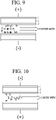
- the electrode is regenerated by separating the ions, which are adsorbed on the electrode, from the electrode as illustrated in FIG. 10 .
- the washing water including the ions separated from the electrode is discharged to the outside.
- Such regeneration may be achieved as no voltage is applied to the electrode or a voltage is applied in opposition to the case of adsorbing the ions.
- the deionization performance is affected by the spacing between the electrodes.
- the spacing between the electrodes As the spacing between the electrodes is increased, the deionization performance is lowered.
- the reasons are as follows. First, as the spacing between the electrodes is increased, the capacitance of a capacitor is decreased. In general, the capacitance of the capacitor is inversely proportional to the spacing between the electrodes. Second, as the spacing between the electrodes is increased, the treatment water more rapidly flows between the electrodes. When the treatment water rapidly flows between electrodes, it is difficult for the ions in the treatment water to be adsorbed on the electrodes. Even if a large number of electrodes are stacked, it is significantly important to properly maintain the spacing between the electrodes.
- US 2015/299002 A1 presents an activated carbon filter (ACF) system.
- the ACF system includes a plurality of activated carbon electrodes, at least one current spreader for each of the plurality of activated carbon electrodes, an electrical connection to provide electrical power to the plurality of activated carbon electrodes via the at least one current spreader, an inlet and an outlet configured to provide fluid through a flow path in the plurality of activated carbon electrodes to remove contaminant from the fluid.
- the system actively deionizes and removes chemical, biological, and/or other particles from a fluid (e.g., tap water).
- WO 01/09907 A1 presents a flow-through capacitor and method for the purification of fluids, like soft water.
- EP 2 098 485 A2 presents an electrode module capable of improving productivity by integrally bonding a current collector and a pair of electrodes using a protective film.
- the electrode module includes a current collector to receive power from an external power supply, and a pair of electrodes to receive power from the current collector, in which the current collector and electrodes are integrally bonded by thermocompression using a protective film.
- the electrode module further comprises a conductive binder formed between the current collector and the electrodes in each electrode module.
- WO 2012/161534 A2 provides an apparatus and method for controlling total dissolved solids, and water treatment apparatus including apparatus for controlling total dissolved solids.
- the total dissolved solid controlling apparatus includes, a filtering unit including a deionizing filter removing dissolved solids from inflow raw water by an input current and, a control unit controlling the input current such that water discharged from the deionizing filter corresponds to target total dissolved solids.
- US 2013/277222 A1 provides a water treatment apparatus having a filter unit that includes a first electrochemical filter and a second electrochemical filter for filtering raw water.
- a control unit drives the first electrochemical filter and the second electrochemical filter.
- the first electrochemical filter and the second electrochemical filter are installed in parallel.
- the control unit controls the second electrochemical filter to perform a water purifying operation when the first electrochemical filter needs to be recycled.
- KR 2012 0032100 A provides a capacitive deionization-based water treatment apparatus using a carbon electrode to improve the operational efficiency of the apparatus by forming the apparatus based on a small area-based absorption electrode.
- the carbon absorption electrode is an electrode containing active carbon and a polymer binder, a woven sheet based on active carbon fiber, a non-woven sheet based on active carbon fiber, an active carbon powder based sheet-shaped electrode, or a conductive carbon absorption electrode.
- a capacitive deionization-based water treatment apparatus is composed of a reactor, a pair of collectors, a pair of absorption electrodes, a rectifier, and a voltage applying line.
- the present invention suggests a filter module for a water treatment apparatus, in which high-efficiency ion removal performance may be obtained by increasing the specific surface area and the permeability, and a water treatment apparatus including the same, to solve the above problem.
- the present invention suggests a filter module for a water treatment apparatus, capable of minimizing the thickness of an electrode by removing the ion exchange membrane and minimizing the volume of the current collector, and a water treatment apparatus including the same.
- the present invention suggests a filter module for a water treatment apparatus, in which stacking is freely performed, so a stacking height may be variously set depending on a required treatment capacity and a required treatment speed, and a water treatment apparatus including the same.
- the present invention suggests a filter module for a water treatment apparatus, which may be manufactured in the form of the curved surface as well as the flat surface, and a water treatment apparatus including the same.
- the present invention suggests a filter module for a water treatment apparatus, capable of uniformly maintaining the ion removal capability of an activated carbon fiber filter by easily removing ions adsorbed onto the activated carbon fiber layer, and a water treatment apparatus including the same.
- the present invention suggests a filter module for a water treatment apparatus, which is directly applicable to an existing water treatment apparatus without changing the shape or the arrangement structure of the filter applied to the water treatment apparatus, and a water treatment apparatus including the same.
- the present invention suggests a filter module for a water treatment apparatus, in which a heterogeneous filter is provided in one housing in a longitudinal direction to reduce the volume of the filter, thereby increasing the space utilization, and a water treatment apparatus including the same.
- One or more objects of the present technique are achieved by subject-matter of the independent claim.
- a water purifier filter includes a filter housing including an inlet and an outlet, and a filter module provided in the filter housing to purify water introduced through the inlet and to supply the water to the outlet.
- a material of the filter module may include sodium orthotitanate (Na4TiO4) to remove a heavy metal under water. Accordingly, under water heavy metal including cadmium may be effectively removed.
- a filter module for a water treatment apparatus includes at least one filter.
- the filter is an activated carbon fiber filter including one activated carbon fiber filter unit or including a plurality of activated carbon fiber filter units which are stacked and each of the activated carbon fiber filters includes a plurality of activated carbon fiber layers including activated carbon fiber and stacked in parallel to each other, a plurality of spacers interposed between the activated carbon fiber layers to prevent short, a pair of current collectors disposed on opposite sides of the stack of activated carbon fiber layers, respectively, and wherein one of the current collectors is connected to one end portion of an activated carbon fiber layer of the stack of activated carbon fiber layers and another of the current collectors is connected to an opposite end portion of an adjacent activated carbon fiber layer of the stack of activated carbon fiber layers such that adjacent activated carbon fiber layers alternately form positive and negative electrodes, respectively; and a power supply unit to apply, through
- the stacking may be freely performed, so the stacking height may be variously set depending on the required treatment capacity and the required treatment speed.
- the activated carbon fiber layer is provided in a form of a fabric having flexibility. Accordingly, the filter may be manufactured in the form of a curved surface as well as the flat surface, the application range of the filter may be enlarged.
- the power supply unit may apply the current in one direction when treatment water is supplied to the activated carbon fiber filter and allows the ion to be adsorbed on the activated carbon fiber layer to remove the underwater ion.
- the power supply unit may apply a current in an opposite direction to the one direction, when the treatment water is supplied to the activated carbon fiber filter, and the ion, which is adsorbed on the activated carbon fiber layer, is discharged under water to clean the activated carbon fiber layer. Accordingly, the ion removal capability of the activated carbon filter may be uniformly maintained by easily removing the ions adsorbed on the activated carbon fiber layer.
- the filter module includes a plurality of activated carbon fiber filters.
- the foreign matters may be more removed from the raw water through several stages, and the hardness of the water may be more lowered.
- the filter module further includes a pre-carbon block filter which purifies water introduced from an outside and then supplies the water to the activated carbon fiber filter. Accordingly, particulate matters and organic compounds contained in the raw water may be more reliably removed.
- the filter of the present invention further includes a post-carbon block filter which receives, purifies, and then discharges water output through the activated carbon fiber filter. Accordingly, the foreign matters may more reliably removed and the water taste may be improved.
- the filter module further includes a UF membrane filter which receives, purifies, and then discharges water output through the activated carbon fiber filter. According to the present invention, viruses and bacteria under the water may be more reliably removed.
- the water output through the activated carbon fiber filter sequentially passes through the UF membrane filter and the post carbon block filter, and the UF membrane filter and the post-carbon block filter are provided in a longitudinal direction and provided inside one filter housing. Accordingly, the present invention is directly applicable to the existing water treatment apparatus without changing the shape or the arrangement structure of the filter applied to the water treatment apparatus.
- the heterogeneous filters are arranged in the longitudinal direction in one filter housing, thereby reducing the volume of the filter and increasing the space utilization. Further, the slim water treatment apparatus may be realized.
- the water may be softened by lowering water hardness.
- high-efficiency ion removal performance may be expected by increasing the specific surface area and the permeability.
- the volume of the current collector may be minimized by removing the ion exchange membrane, thereby minimizing the thickness of the electrode.
- the stacking is freely performed, so the stacking height may be variously set depending on the required treatment capacity and the required treatment speed.
- the filter may be manufactured in the form of a curved shape as well as a flat surface, so the application range of the filter may be enlarged.
- the ion removal capability of the activated carbon fiber filter may be uniformly maintained by easily removing the ions adsorbed to the activated carbon fiber layer.
- foreign matters may be more removed as the raw water passes through several stages, and the hardness of the water may be more lowered.
- particulate matter and organic compounds contained in the raw water may be more reliably removed.
- the foreign matters may be more reliably removed and the water taste may be improved.
- viruses and bacteria under the water may be more reliably removed.
- the present invention is directly applicable to the existing water treatment apparatus without changing the shape or the arrangement structure of the filter applied to the water treatment apparatus.
- a heterogeneous filter is provided in one housing in a longitudinal direction to reduce the volume of the filter, thereby increasing the space utilization and realizing the slim water treatment apparatus. Further, various effects may be understood as being produced through the features suggested in the detailed embodiments of the present invention.
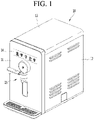
- FIG. 1 is a perspective view illustrating a water treatment apparatus according to the present invention.
- the water treatment apparatus may include various purification apparatuses such as a water purifier, a water softener, and the like.
- the water treatment apparatus may correspond to a purifying unit installed in a washing machine, a dishwasher, a refrigerator, or the like.
- a water treatment apparatus may include a purifier by way of example.
- the water purifier is to purify the water directly supplied from an external water source, and then to cool, heat, and extract the water.
- the water purifier may be a direct water type water purifier.
- the direct water type water purifier refers to a water purifier having the structure in which the purified water is extracted without a water tank for storing the purified water when the user extracts the water.
- a water purifier 10 may have an outer appearance formed by combining a plurality of panels with each other.
- the water purifier 10 may have a substantially hexahedral shape as a front panel 11 forming a front outer appearance, side panels 12 forming outer appearances of opposite side surfaces, a top surface panel 13 forming a top surface outer appearance, and a base panel forming a bottom surface outer appearance are combined with each other.
- a plurality of parts for purifying water are provided in an internal space formed by combining the panels.
- the front panel 11 is provided thereon with an operation display unit 14 to allow a user to input an operation command of the water purifier 10 and to display the operation state of the water purifier 10.
- the operation display unit 14 is provided in the form of a plurality of buttons or a touch screen such that light is irradiated to each button.
- the selected button is irradiated with light to allow the user to easily recognize whether the button is selected, and to simultaneously perform the function of the display unit.
- the operation display unit 14 includes a button to select the kind of water to be extracted, that is, a button to select cold water, hot water or purified water (water at the room temperature), a button to continuously dispense water, a button to identify a power state of the hot water, and a display unit to display the temperatures of the hot water or the cold water.
- the operation display unit 14 may further include a button to perform an additional function, and some buttons may be omitted from the operation display unit 14.
- the water chute 15 is provided so that the user may operate the water chute 15 to dispense the purified water.
- the water chute 15 has a function of opening and closing a water outlet to allow the user to extract the purified water, so the water chute 15 is referred to as an opening/closing device or an opening/closing nozzle.
- the water chute 15 is configured to dispense purified water, cold water, or hot water depending on the functions of the water purifier 10 by the operation of the user.
- a tray is provided below the water chute 15, in detail, at a front lower end portion of the front panel 11 to receive water dropped from the water chute 15.
- the tray is provided in the shape of a hexahedron having an internal space and provided on the top surface thereof with a grill-shaped cover to filter out foreign matters.
- the tray is movable forward from the front panel 11. Such movement of the tray allows the user to put purified water even in a bottle having a higher height or a container having a wider bottom surface.
- the tray further includes a buoy for checking the level of water contained in the internal space thereof.
- the user may recognize the timing to empty water from the tray by recognizing such a buoy, thereby improving the convenience of user.
- a plurality of components including a refrigerant cycle to cool water, a cold water generating unit to generate cold water, and a hot water generating unit to heat water are received inside the panels forming the outer appearance of the water purifier 10.
- the water purifier 10 may include a compressor to compress the refrigerant into a gas-phase refrigerant having a high temperature and high pressure, a condenser to condense the refrigerant discharged from the compressor to a liquid-phase refrigerant having the high temperature and high pressure, and a condensing fan to exchange heat with the condenser.
- the water purifier 10 may further include a filter assembly to filter out foreign matters contained in water supplied from the water supply source.
- the filter assembly may include a carbon filter.
- the water purifier 10 may further include an expansion valve to expand the refrigerant discharged from the condenser to a two-phase refrigerant having a low temperature and low pressure and an evaporator through which the two-phase refrigerant having the low temperature and low pressure, which is subject to the expansion valve, flows.
- the water purifier 10 may further include a cold water generating unit including the evaporator and a cold water pipe through which the cold water flows.
- the water purifier 10 may further include a hot-water heater to heat the water to be supplied to a set temperature.
- FIG. 2 is a view illustrating the piping feature of the water treatment apparatus illustrated in FIG. 1 .
- a water supply line L may extend from a water supply source S to the water chute 15 of the water purifier 10, and various valves and purified water parts may be connected to the water supply line L.
- the water supply line L is connected to the water supply source S, for example, a faucet at home, and a filter assembly 17 is disposed at a certain point in the water supply line L to filter out foreign matters from drinking water supplied from the water supply source S.
- a water supply valve 61 and a flow sensor 70 are sequentially arranged on the water supply line L connected to an outlet end of to the filter assembly 17. Therefore, when a supply amount sensed by the flow sensor 70 reaches a set amount, the water supply valve 61 may be controlled to be closed.
- a hot water supply line L1, a cold water supply line L3, and a cooling water supply line L2 may branch from a certain point of the water supply line L extending from the outlet end of the flow sensor 70.
- a purified water dispensing valve 66 is mounted at an end portion of the water supply line L extending from the outlet end of the flow sensor 70, and a hot water dispensing valve 64 is mounted at an end portion of the hot water supply line L1.
- a cold water dispensing valve 65 may be mounted at an end portion of the cold water supply line L3, and a cooling water valve 63 may be mounted at a certain point of the cooling water supply line L2. The cooling water valve 63 may adjust an amount of cooling water supplied to a cold water generating unit 20.
- all water supply lines extending from the outlet ends of the hot water dispensing valve 64, the cold water dispensing valve 65, and the purified water dispensing valve 66 are connected to the water chute 15.
- the purified water, the cold water, and the hot water may be configured to be connected to a single outlet, and may be configured to be connected to independent outlets, respectively, according to occasions.
- the cooling water supply line L2 may have a refrigerant cycle to cool the cooling water.
- the refrigerant cycle may include a compressor, a condenser, an expansion valve, an evaporator, and the like.
- the cold water may be dispensed through the water chute 15.
- the water treatment apparatus including the purifier having the above components includes a filter module including at least one filter to generate purified water from the raw water.
- the filter module will be described later.
- the filter module for the water treatment apparatus includes a first and a second activated carbon fiber filter.
- FIG. 3 is a schematic view illustrating an activated carbon fiber filter which is some component of the filter module for the water treatment apparatus according to the present invention.
- the activated carbon fiber filter 100 includes at least one activated carbon fiber filter unit 100a stacked.
- the activated carbon fiber filter 100 may include one activated carbon fiber filter unit 100a or may be formed by stacking a plurality of activated carbon fiber filter units 100a.
- the activated carbon fiber filter unit 100a includes a plurality of activated carbon fiber layers 110 including activated carbon fiber and stacked in parallel to each other, a plurality of spacers 130 interposed between the activated carbon fiber layers to prevent short, a pair of current collectors 120 connected with one end portion or an opposite end portion of the activated carbon fiber layers 110 stacked, and power supply units 140 and 150 to apply a current to the activated carbon fiber layer 110 through the current collector 120 such that adjacent activated carbon fiber layers 110 alternately form a positive electrode and a negative electrode.
- the activated carbon fiber layer 110 includes an activated carbon fiber.
- the activated carbon fiber may refer to that activated carbon is processed in the fiber to improve the adsorption performance of the activated carbon.
- a material to be adsorbed are diffused into a hole referred to as a macropore formed in the surface of the activated carbon and finally adsorbed to an internal mesopore or a micropore.
- mesopores or micropores are formed in the surface instead of macropores. Accordingly, the material to be adsorbed is directly adsorbed on the mesopore or the micropore without the diffusion.
- the material to be adsorbed may be adsorbed at a rapid speed.
- the surface area becomes wider than that of the existing activated carbon. Accordingly, an adsorption amount of adsorbed material and the removal speed of the adsorbed material may be increased.
- the activated carbon fiber layer 110 may be processed in various forms.
- the activated carbon fiber layer 110 may have the form of a fabric having flexibility.
- the activated carbon fiber filter 100 may be provided in the form of a curved surface as well as a flat surface. Accordingly, the application range of the filter may be enlarged.
- the activated carbon fiber filter 100 may be installed at a position in which the installation space of the filter is not ensured.
- the number of activated carbon fiber layers 110 may be adjusted depending on the desired adjustment degree of hardness. For example 20 to 40 activated carbon fiber layers 110 may be stacked in one activated carbon fiber filter unit 100a.
- FIG. 8 is a photography having an enlarged activated carbon fiber layer which is some components of the activated carbon fiber filter illustrated in FIG. 3 .
- the activated carbon fibers are woven in the form of a fabric.
- permeability may be ensured.
- a mesopore or a micropore is formed in the surface of the activated carbon fiber.
- the activated carbon fiber layer 110 has an activated carbon fiber woven in the form of a fabric, so the higher permeability is ensured. Accordingly, the activated carbon fiber layer 110 may allow raw water to pass therethrough rapidly. In addition, the activated carbon fiber layer may have a wider surface area, and may rapdily adsorb and remove the material to be adsorbed, which is contained in the raw water passing through mesopores or micropores formed in the surface of the activated carbon fiber.
- the spacers 130 are disposed between the activated carbon fiber layers 110.
- the spacers 130 form a gap between the activated carbon fiber layers 110 to prevent short between the activated carbon fiber layers 110.
- the raw water may be purified while passing between the activated carbon fiber layers 110 through the spacer 130.
- the spacer 130 may be formed of a water-permeable material, while being an insulator.
- the spacer 130 may be formed of a nylon material.
- a pair of current collectors 120 is provided, connected with one end portion or an opposite end portion of the activated carbon fiber layers 110, which are stacked, and provided in the form of an electric conductor.
- the current collector 120 may be formed by applying activated carbon on opposite surfaces of a graphite foil.
- the power supply units 140 and 150 may include a power source 140 and a wire 150.
- a voltage may be applied within a range in which ion adsorption is possible, without decomposing the raw water.
- the power source 140 may apply a voltage of 1.5V.
- the current collector 120 has a positive electrode or a negative electrode depending on the direction of a current flowing through the power supply unit 140 and 150.
- the current collector 120 disposed at the left side of the drawing when the current collector 120 disposed at the left side of the drawing is a positive electrode, the current collector 120 disposed at the right side of the drawing may be a negative electrode.
- the current collector 120 disposed at the left side of the drawing is a negative electrode
- the current collector 120 disposed at the right side of the drawing may be a positive electrode
- current collectors 120 disposed on opposite sides of the activated carbon fiber layer 110 represent positive and negative electrodes, respectively, depending on the direction that the current flows.
- the current collector at which the positive electrode is formed is referred to as a positive electrode
- the current collector at which the negative electrode is formed is referred to as a negative electrode
- Adjacent activated carbon fiber layers of the plurality of activated carbon fiber layers 110 have to alternately have the positive electrode and the negative electrode.
- the meaning of "adjacent” refers to that the adjacent activated carbon fiber layers are close to each other while interposing a spacer 130 therebetween.
- the activated carbon fiber layer 110 disposed at the upper most part of the drawing may be adjacent to the second activated carbon fiber layer 110, which is positioned right thereunder, while interposing the spacer 130 therebetween.
- positive and negative electrodes have to be formed at the current collectors 120 disposed at opposite sides of the activated carbon fiber layer 110, and the adjacent activated carbon fiber layers 110 of the plurality of activated carbon fiber layers 110, which are stacked, has to be alternately connected with the positive electrode and the negative electrode, respectively.
- the first activated carbon fiber layer 110 disposed at the upper most part of the drawing may be connected with the positive electrode at the left side of the drawing and the second activated carbon fiber layer 110 disposed under the first activated carbon fiber layer 110 may be connected with the negative electrode at the right side of the drawing.
- the third activated carbon fiber layer 110 disposed under the second activated carbon fiber layer 110 may be connected with the positive electrode at the right side and the fourth activated carbon fiber layer 110 disposed under the third activated carbon fiber layer 110 may be connected with the negative electrode at the right side of the drawing.
- the activated carbon fiber layer 110 connected with the positive electrode is electrically insulated from the negative electrode
- the activated carbon fiber layer 110 connected with the negative electrode is electrically insulated from the positive electrode
- the activated carbon fiber layer 110 disposed at the upper most part of the drawing may be connected with the negative electrode at the right side and the activated carbon fiber layer 110, which is disposed under the activated carbon fiber layer 110 disposed at the upper most part of the drawing, may be connected with the positive electrode at the left side.
- the activated carbon fiber layer 110 disposed at the upper most part of the drawing may be connected with the negative electrode at the left side and the activated carbon fiber layer 110 disposed, which is disposed under the activated carbon fiber layer 110 disposed at the upper most part of the drawing, may be connected with the positive electrode at the right side.
- the activated carbon fiber layer 110 disposed at the upper most part of the drawing may be connected with the positive electrode at the right side and the activated carbon fiber layer 110, which is disposed under the activated carbon fiber layer 110 disposed at the upper most part of the drawing may be connected with the negative electrode at the left side.
- the activated carbon fiber layer 110 connected with the positive electrode is electrically insulated from the negative electrode
- the activated carbon fiber layer 110 connected with the negative electrode is electrically insulated from the positive electrode
- a negative electrode is spaced apart from the activated carbon fiber layer 110 connected with the positive electrode such that the activated carbon fiber layer 110 connected with the positive electrode is electrically insulated from the negative electrode.
- the positive electrode is spaced apart from the activated carbon fiber layer 110 connected with the negative electrode such that the positive electrode is electrically insulated from the activated carbon fiber layer 110 connected with the negative electrode.
- the activated carbon fiber layer 110 disposed at the upper most part may have a connector protruding to one side from one end portion thereof, and the second activated carbon fiber layer 110 may have a connector protruding to an opposite side from an opposite end portion thereof.
- an odd-numbered activated carbon fiber layer 110 may have a connector protruding to one side from one end portion thereof, and an even-numbered activated carbon fiber layer 110 may have a connector protruding to an opposite side from an opposite end portion thereof.
- an electrode formed at the one side may be connected with the connector of the odd-numbered activated carbon fiber layer 110 protruding to the one side, and an electrode formed at the opposite side may be connected with the connector of the even-numbered activated carbon fiber layer 110 protruding from the opposite side.
- the one side and the opposite side may refer to directions opposite to each other or may refer to directions perpendicular to each other.
- the first activated carbon fiber layer 110 disposed at the upper most part of the drawing may have a connector protruding to the one side from one-side front portion thereof and the second activated carbon fiber layer 110 formed under the first activated carbon fiber layer 110 may have a connector protruding to the one side from one-side rear portion thereof.
- an odd-numbered activated carbon fiber layer 110 may have a connector protruding to one side from one-side front portion thereof
- an even-numbered activated carbon fiber layer 110 may have a connector protruding to one side from the one-side rear portion thereof.
- the electrodes formed in front of the one side may be connected with all connectors of the odd-numbered activated carbon fiber layers 110, which protrudes to the one side from one-side front portion thereof, and the electrodes formed in back of the one side may be connected with all connectors of the even-numbered activated carbon fiber layer 110, which protrude to the one side from one-side rear portion thereof.
- the structure in which the adjacent activated carbon fiber layers 110 of the plurality of activated carbon fiber layers 110, which are stacked, are alternately connected with the positive electrode and the negative electrode may bring various embodiments.
- ions, such as heavy metals, contained in raw water passing between the activated carbon fiber layers 110 separated from each other by the spacer 130 may be adsorbed and removed.
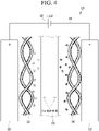
- FIG. 4 is a schematic view illustrating that water is purified through the activated carbon fiber filter illustrated in FIG. 3
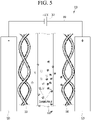
- FIG. 5 is a schematic view illustrating that the activated carbon fiber filter illustrated in FIG. 3 is cleaned.
- the raw water may be purified.
- the raw water may easily pass between the activated carbon fiber layers 110 through the spacer 130, which has a permeable property, interposed between the activated carbon fiber layers 110, thereby preventing short-circuiting and securing the flow passage.
- the activated carbon fiber layer 110 reaches a state in which the activated carbon fiber layer 110 does not adsorb ions any more.
- the activated carbon fiber layer 110 reaches the state, it is necessary to separate the adsorbed ions from the activated carbon fiber layer 110 to regenerate the activated carbon fiber layer 110 as illustrated in FIG. 5 .
- the supply of a current may be cut off, or a current may be allowed to flow in a direction opposite to the direction of a current applied when ions are adsorbed on the activated carbon fiber layer 110.
- the activated carbon fiber layer 110 disposed at the left side of the drawing is negatively charged and the activated carbon fiber layer 110 disposed at the right side of the drawing is positively charged by changing the flow of current, thereby regenerating the activated carbon fiber layer 110.
- the ions (-) adsorbed on the activated carbon fiber layer 110 at the left side in the water purifying process are separated from the activated carbon fiber layer 110, which is negatively charged, at the left side.
- the ions (+) adsorbed on the activated carbon fiber layer 110, which is positively charged, at the right side in the water purifying process are separated from the activated carbon fiber layer 110 at the right side.
- the ions (+) and the ions (-) separated from both activated carbon fiber layer 110 are discharged to the outside together with the cleaning water as described above.
- the ions adsorbed on the activated carbon fiber layer 110 are removed through the process of cleaning the activated carbon fiber layer 110, the ion removal capability of the activated carbon fiber filter 100 is regenerated, so the ion removal capability is uniformly maintained.
- the activated carbon fiber filter unit 100a configured as described above may constitute, in the structure of a single body, the activated carbon fiber filter 100, or a plurality of activated carbon fiber filter units 100a may be provided and stacked in several layers to constitute the activated carbon fiber filter 100.
- the ion exchange membrane which is essentially provided to primarily remove the ions in a conventional technology, may be removed, thereby minimizing the volume of the current collector. Accordingly, the thickness of the electrode may be minimized.
- the stacking may is freely performed, so the stacking height may be variously set depending on the required treatment capacity and the required treatment speed
- the ion exchange membrane is removed, the scope of the present invention is not limited thereto. If necessary, the ion exchange membrane may be selectively used to more increase the ion removal rate of the activated carbon fiber filter 100.
- the ion exchange membrane When the ion exchange membrane is used as described above, the ion exchange membrane may be disposed between the spacer 130 and the activated carbon fiber layer 110.
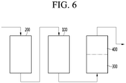
- FIG. 6 is a schematic view illustrating a filter module of the water treatment apparatus.
- FIG. 7 is a schematic view illustrating a filter module of the water treatment apparatus according to the present invention.
- the filter module may include a plurality of activated carbon fiber filters 100.
- raw water passes through the activated carbon fiber filters 100 and 500 several times. Accordingly, various ions contained in the raw water may be more adsorbed and removed on the activated carbon fiber layer 110.
- the number of the activated carbon fiber filters 100 and 500 may be freely increased or decreased depending on the state of the raw water and required water purification performance.
- the filter module may further include a pre-carbon block filter 200 which purifies water introduced from the outside and then supplies the water to the activated carbon fiber filter 100.
- the raw water introduced from the outside may be preliminarily filtered while passing through the pre-carbon block filter 200 and then filtered while passing through the activated carbon fiber filter 100, before supplied to the activated carbon fiber filter 100.
- pre-carbon block filter 200 When the pre-carbon block filter 200 is provided as described above, particulate matter and organic compounds contained in the raw water may be more reliably removed.
- the water treatment apparatus filter may further include a post-carbon block filter 400 which receives, purifies, and then discharges water output through the activated carbon fiber filter 100.
- the water output through the activated carbon fiber filter 100 may be additionally filtered while passing through the post-carbon block filter 400 without directly being supplied to a user, and then may be supplied to the user.
- the post-carbon block filter 400 When the post-carbon block filter 400 is provided, foreign matters may be more removed, so the water taste may be improved.
- the filter module may further include an UF membrane filter 300 which receives, purifies, and then discharges water output through the activated carbon fiber filter 100.
- the water output through the activated carbon fiber filter 100 may be additionally filtered while passing through the UF membrane filter 300 without directly being supplied to a user, and then may be supplied to the user.
- viruses and bacteria in the water may be more reliably removed.
- the water which is output through the activated carbon fiber filter 100, is discharged after sequentially passing through the UF membrane filter 300 and the post-carbon block filter 400.
- the UF membrane filter 300 and the post-carbon block filter 400 may be arranged in a longitudinal direction and installed in one filter housing.
- the filtering efficiency may be enhanced, and the flow rate may be maintained.
- the present invention may be directly applied through simple work of replacing an existing filter with new one without expanding the filter installation space formed in the water treatment apparatus.
- the volume of the filter may be reduced to increase the space utilization. Further, the slim water treatment apparatus may be realized.
- water for treatment which is introduced from the outside, passes through the pre-carbon block filter 200.
- the treatment water subject to the primary purification passes through the activated carbon fiber filter 100.
- ions contained in the treatment water are adsorbed and removed on the activated carbon fiber filter 100, thereby performing secondary purification for the treatment water.
- the treatment water subject to the secondary purification passes through a high-specification UF membrane filter 300.
- the viruses and bacteria contained in the treated water are removed, thereby performing tertiary purification for the treated water.
- the treatment water subject to the tertiary purification passes through the post-carbon block filter 400. In this process, the foreign matters contained in the treatment water are further removed, thereby performing fifth purification for the treatment water.
- the treatment water passes through the filter module including the pre-carbon block filter 200, the activated carbon fiber filter 100, the UF membrane filter 300, and the post-carbon block filter 400, thereby lowering the hardness in the water, more removing foreign matters including harmful underwater microorganism, and improving water taste.
- water for treatment which is introduced from the outside, passes through the pre-carbon block filter 200.
- the treatment water subject to the primary purification passes through the activated carbon fiber filter 100.
- ions contained in the treatment water are adsorbed and removed on the activated carbon fiber filter 100, thereby performing secondary purification for the treatment water.
- the treatment water subject to the secondary purification passes through a second activated carbon fiber filter 500.
- ions contained in the treatment water are adsorbed and removed on the second activated carbon fiber filter 500, thereby performing tertiary purification for the treatment water.
- the treatment water subject to the tertiary purification passes through a high-specification UF membrane filter 300.
- the viruses and bacteria contained in the treated water are removed, thereby performing fourth purification for the treated water.
- the treatment water subject to the fourth purification passes through the post-carbon block filter 400.
- the foreign matters contained in the treatment water are further removed, thereby performing fifth purification for the treatment water.
- the treatment water passes through the filter module including the pre-carbon block filter 200, the activated carbon fiber filter 100, the second activated carbon fiber filter 500, the UF membrane filter 300, and the post-carbon block filter 400, thereby lowering the hardness in the water, more removing foreign matters including harmful underwater microorganism, and improving water taste.
Landscapes
- Chemical & Material Sciences (AREA)
- Chemical Kinetics & Catalysis (AREA)
- Engineering & Computer Science (AREA)
- Water Supply & Treatment (AREA)
- Life Sciences & Earth Sciences (AREA)
- Hydrology & Water Resources (AREA)
- Organic Chemistry (AREA)
- Environmental & Geological Engineering (AREA)
- Analytical Chemistry (AREA)
- Health & Medical Sciences (AREA)
- General Chemical & Material Sciences (AREA)
- Electrochemistry (AREA)
- Molecular Biology (AREA)
- Geology (AREA)
- Materials Engineering (AREA)
- Clinical Laboratory Science (AREA)
- Water Treatment By Sorption (AREA)
- Separation Using Semi-Permeable Membranes (AREA)
- Water Treatment By Electricity Or Magnetism (AREA)
Claims (10)
- Appareil de traitement d'eau (10) comportant :une pluralité de panneaux (11, 12, 13) combinés les uns avec les autres pour former un aspect extérieur de l'appareil de traitement d'eau (10) ; etun module filtrant pour retirer des corps étrangers de l'eau brute qui est introduite, dans lequel le module filtrant comporte :un filtre à fibres de carbone activé (100) incluant une unité filtrante à fibres de carbone activé (100a) ou incluant une pluralité d'unités filtrantes à fibres de carbone activé (100a) qui sont empilées ;un second filtre à fibres de carbone activé (500) configuré pour recevoir la sortie d'eau à travers le filtre à fibres de carbone activé (100) ;un pré-filtre à plaquette de carbone (200) configuré pour purifier l'eau introduite depuis un extérieur et ensuite fournir l'eau au filtre à fibres de carbone activé (100) ;un filtre à membrane UF (300) configuré pour recevoir la sortie d'eau à travers le second filtre à fibres de carbone activé (500), purifier puis évacuer l'eau ; etun post-filtre à plaquette de carbone (400) configuré pour recevoir la sortie d'eau à travers le filtre à membrane UF (300), purifier puis évacuer l'eau ;dans lequel chacun des filtres à fibres de carbone activé (100, 500) inclut :une pluralité de couches de fibres de carbone activé (110) incluant des fibres de carbone activé et empilées parallèlement les unes aux autres ;une pluralité d'éléments d'espacement (130) intercalés entre les couches de fibres de carbone activé (110) pour empêcher un court-circuit ;une paire de collecteurs de courant (120) disposés sur des côtés opposés de la pile de couches de fibres de carbone activé (110), respectivement, et dans lequel l'un des collecteurs de courant (120) est relié à une partie d'extrémité d'une couche de fibres de carbone activé (110) de la pile de couches de fibres de carbone activé (110) et un autre des collecteurs de courant (120) est relié à une partie d'extrémité opposée d'une couche adjacente de fibres de carbone activé (110) de la pile de couches de fibres de carbone activé (110) de telle sorte que des couches adjacentes de fibres de carbone activé (110) forment de manière alternée des électrodes positive et négative, respectivement ; etune unité d'alimentation (140, 150) pour appliquer, via le collecteur de courant (120), un courant à la couche de fibres de carbone activé (110) formant l'électrode positive et l'électrode négative.
- Appareil de traitement d'eau (10) selon la revendication 1, dans lequel la couche de fibres de carbone activé (110) est fournie sous forme de tissu ayant de la souplesse.
- Appareil de traitement d'eau (10) selon la revendication 1, dans lequel l'unité d'alimentation (140, 150) est configurée pour appliquer le courant dans une première direction lorsque de l'eau de traitement est fournie aux filtres à fibres de carbone activé (100, 500) pour permettre d'adsorber les ions sur la couche de fibres de carbone activé (110) pour retirer les ions sous l'eau.
- Appareil de traitement d'eau (10) selon la revendication 3, dans lequel l'unité d'alimentation (140, 150) est configurée pour appliquer le courant dans une direction opposée à la première direction, lorsque l'eau de traitement est fournie aux filtres à fibres de carbone activé (100, 500), pour décharger les ions, qui sont adsorbés sur la couche de fibres de carbone activé (110), sous l'eau pour nettoyer la couches de fibres de carbone activé (110).
- Appareil de traitement d'eau (10) selon la revendication 1,
dans lequel le filtre à membrane UF (300) et le post-filtre à plaquette de carbone (400) sont agencés dans une direction longitudinale et fournis dans un boîtier de filtre. - Appareil de traitement d'eau (10) selon l'une quelconque des revendications 1 à 5, dans lequel une ligne d'alimentation en eau, par laquelle s'écoule la sortie d'eau purifiée à travers le module filtrant, est divisée en une pluralité de lignes d'alimentation en eau (L1, L2, L3).
- Appareil de traitement d'eau (10) selon la revendication 6, dans lequel la ligne d'alimentation en eau, par laquelle s'écoule la sortie d'eau purifiée à travers le module filtrant, est divisée en une ligne d'alimentation en eau chaude (L1) et une ligne d'alimentation en eau froide (L3).
- Appareil de traitement d'eau (10) selon la revendication 7, dans lequel chacune des lignes d'alimentation en eau (L1, L2, L3) est pourvue sur celle-ci d'une vanne (64, 65, 66) pour commander un écoulement d'eau.
- Appareil de traitement d'eau (10) selon la revendication 7, dans lequel de l'eau froide, de l'eau chaude ou de l'eau purifiée s'écoulant à travers les lignes d'alimentation en eau (L1, L2, L3) respectives est fournie à un extérieur du purificateur d'eau à travers une sortie.
- Appareil de traitement d'eau (10) selon la revendication 7, dans lequel un élément de chauffage d'eau chaude (30) est agencé sur la ligne d'alimentation en eau chaude (L1) pour chauffer l'eau purifiée, et dans lequel une unité de production d'eau froide (20) est agencée sur la ligne d'alimentation en eau froide (L3) pour refroidir l'eau purifiée.
Applications Claiming Priority (2)
| Application Number | Priority Date | Filing Date | Title |
|---|---|---|---|
| KR1020160167765A KR20180066665A (ko) | 2016-12-09 | 2016-12-09 | 수처리 장치용 필터모듈 및 이를 포함하는 수처리 장치 |
| PCT/KR2017/014390 WO2018106061A1 (fr) | 2016-12-09 | 2017-12-08 | Module de filtre pour appareil de traitement d'eau, et appareil de traitement d'eau comprenant ledit module de filtre |
Publications (3)
| Publication Number | Publication Date |
|---|---|
| EP3552680A1 EP3552680A1 (fr) | 2019-10-16 |
| EP3552680A4 EP3552680A4 (fr) | 2020-05-20 |
| EP3552680B1 true EP3552680B1 (fr) | 2022-04-13 |
Family
ID=62492062
Family Applications (1)
| Application Number | Title | Priority Date | Filing Date |
|---|---|---|---|
| EP17878460.9A Active EP3552680B1 (fr) | 2016-12-09 | 2017-12-08 | Appareil de traitement d'eau comprenant un module de filtre |
Country Status (4)
| Country | Link |
|---|---|
| US (1) | US20200071201A1 (fr) |
| EP (1) | EP3552680B1 (fr) |
| KR (1) | KR20180066665A (fr) |
| WO (1) | WO2018106061A1 (fr) |
Families Citing this family (8)
| Publication number | Priority date | Publication date | Assignee | Title |
|---|---|---|---|---|
| KR102210951B1 (ko) | 2019-02-19 | 2021-02-02 | 주식회사 이노켐텍 | 유로를 가지는 교환막/수처리필터/정수장치 |
| CN109942046B (zh) * | 2019-04-24 | 2021-06-15 | 江西理工大学 | 一种阵列式橙质基活性炭除臭去污设备 |
| USD987772S1 (en) | 2020-07-02 | 2023-05-30 | Qingdao Ecopure Filter Co., Ltd. | Water filter |
| CN112221280A (zh) * | 2020-09-02 | 2021-01-15 | 安徽省嘉瑞医药科技有限公司 | 一种用于医药呼吸袋生产的废气收集装置 |
| USD1019884S1 (en) | 2021-08-03 | 2024-03-26 | Qingdao Ecopure Filter Co., Ltd. | Water filter |
| USD1016970S1 (en) | 2021-09-03 | 2024-03-05 | Qingdao Ecopure Filter Co., Ltd | Water filter |
| CN114314957B (zh) * | 2021-12-31 | 2023-11-24 | 武汉大学 | 电絮凝—纤维过滤水处理装置用的电极、电絮凝—纤维过滤水处理装置及其使用方法 |
| USD1025290S1 (en) * | 2024-01-04 | 2024-04-30 | Hongxia Huang | Water filter |
Family Cites Families (12)
| Publication number | Priority date | Publication date | Assignee | Title |
|---|---|---|---|---|
| AU6503600A (en) * | 1999-07-30 | 2001-02-19 | Marc D. Andelman | Flow-through capacitor and method |
| KR20090093323A (ko) * | 2008-02-29 | 2009-09-02 | 삼성전자주식회사 | 탈이온화 장치 및 그 제조방법 |
| KR101290728B1 (ko) * | 2008-03-07 | 2013-07-26 | 삼성전자주식회사 | 전극 모듈 및 이를 이용한 탈이온화 장치 |
| KR101110709B1 (ko) * | 2009-02-04 | 2012-03-14 | 송정환 | 고체 지지체에 담지된 dna촉매 필터를 이용하는 다단계 정수시스템 |
| KR100953085B1 (ko) * | 2009-09-09 | 2010-04-19 | 제이에이건설주식회사 | 축전 탈이온화 방식을 이용한 하, 폐수 처리 시스템 |
| KR101732188B1 (ko) * | 2010-09-28 | 2017-05-25 | 한국전력공사 | 탄소전극을 이용한 전기흡착식 수처리장치 |
| KR101675749B1 (ko) * | 2010-12-30 | 2016-11-16 | 코웨이 주식회사 | 수처리 장치 및 이를 이용한 수처리 방법 |
| US9249038B2 (en) * | 2011-03-03 | 2016-02-02 | Lg Electronics Inc. | Water purifier |
| GB201107841D0 (en) * | 2011-05-11 | 2011-06-22 | Enpar Technologies Inc | Liquid flowpaths in CDI having porous electrodes |
| KR101947994B1 (ko) * | 2011-05-25 | 2019-02-14 | 코웨이 주식회사 | 수처리 기기 |
| KR20150059202A (ko) * | 2013-11-21 | 2015-06-01 | (주) 청연 | 투수성 하이브리드 활성탄소섬유를 이용한 cdi용 전극 |
| WO2015164347A1 (fr) * | 2014-04-22 | 2015-10-29 | Purewater Medical, Inc. | Système et procédé de filtre à charbon actif |
-
2016
- 2016-12-09 KR KR1020160167765A patent/KR20180066665A/ko not_active Application Discontinuation
-
2017
- 2017-12-08 US US16/467,741 patent/US20200071201A1/en active Pending
- 2017-12-08 WO PCT/KR2017/014390 patent/WO2018106061A1/fr unknown
- 2017-12-08 EP EP17878460.9A patent/EP3552680B1/fr active Active
Also Published As
| Publication number | Publication date |
|---|---|
| US20200071201A1 (en) | 2020-03-05 |
| EP3552680A1 (fr) | 2019-10-16 |
| WO2018106061A1 (fr) | 2018-06-14 |
| EP3552680A4 (fr) | 2020-05-20 |
| KR20180066665A (ko) | 2018-06-19 |
Similar Documents
| Publication | Publication Date | Title |
|---|---|---|
| EP3552680B1 (fr) | Appareil de traitement d'eau comprenant un module de filtre | |
| EP3563920A1 (fr) | Filtre d'appareil de traitement d'eau et appareil de traitement d'eau le comprenant | |
| KR101948006B1 (ko) | 수처리 장치 | |
| JP5146437B2 (ja) | 給湯機 | |
| KR102247227B1 (ko) | 수처리 장치용 필터 및 이를 포함하는 수처리 장치 | |
| KR102301795B1 (ko) | 카본 전극 필터를 포함하는 가정용 정수기 | |
| JP2011043252A (ja) | 給湯機 | |
| KR20120030834A (ko) | 전기흡착식 수처리장치 | |
| KR20180082251A (ko) | 수처리 장치용 필터 및 이를 포함하는 수처리 장치 | |
| KR102267917B1 (ko) | 수처리 장치용 필터 | |
| KR20150042481A (ko) | 축전식 쌍 전해조 에너지 교차 재이용 해수 담수화 장치 | |
| KR100801916B1 (ko) | 전극식 연수기 | |
| KR101394112B1 (ko) | 전기 흡착식 수처리 셀, 이를 이용한 전기 흡착식 수처리 장치 및 방법. | |
| WO2012090062A1 (fr) | Ensemble condensateur à passage de fluide pour le traitement d'un fluide | |
| KR20100089251A (ko) | 축전 탈 이온화 장치, 이를 이용한 축전 탈 이온화 방법 및이를 이용한 담수화 장치, 폐수 처리 장치 | |
| KR102237038B1 (ko) | 가정 정수기용 카본 전극 필터 모듈 | |
| CN113402079A (zh) | 一种家用净水装置 | |
| EP3031779B1 (fr) | Dispositif de traitement d'eau de type cdi | |
| KR20210021836A (ko) | 수처리 장치용 필터 | |
| KR102572460B1 (ko) | 수 처리 장치용 필터 | |
| JP2005087898A (ja) | 静電脱イオン装置および静電脱イオン方法 | |
| JP2012011344A (ja) | 水処理装置および給湯機 | |
| KR101981343B1 (ko) | 초순수 및 냉수 생산 시스템 및 방법 | |
| JP4006389B2 (ja) | 静電脱イオン装置および静電脱イオン方法 | |
| KR20220096174A (ko) | 전기탈이온 방식의 정수기 |
Legal Events
| Date | Code | Title | Description |
|---|---|---|---|
| STAA | Information on the status of an ep patent application or granted ep patent |
Free format text: STATUS: THE INTERNATIONAL PUBLICATION HAS BEEN MADE |
|
| PUAI | Public reference made under article 153(3) epc to a published international application that has entered the european phase |
Free format text: ORIGINAL CODE: 0009012 |
|
| STAA | Information on the status of an ep patent application or granted ep patent |
Free format text: STATUS: REQUEST FOR EXAMINATION WAS MADE |
|
| 17P | Request for examination filed |
Effective date: 20190701 |
|
| AK | Designated contracting states |
Kind code of ref document: A1 Designated state(s): AL AT BE BG CH CY CZ DE DK EE ES FI FR GB GR HR HU IE IS IT LI LT LU LV MC MK MT NL NO PL PT RO RS SE SI SK SM TR |
|
| AX | Request for extension of the european patent |
Extension state: BA ME |
|
| DAV | Request for validation of the european patent (deleted) | ||
| DAX | Request for extension of the european patent (deleted) | ||
| A4 | Supplementary search report drawn up and despatched |
Effective date: 20200421 |
|
| RIC1 | Information provided on ipc code assigned before grant |
Ipc: C02F 1/44 20060101ALI20200415BHEP Ipc: C02F 1/469 20060101AFI20200415BHEP Ipc: B01D 35/30 20060101ALI20200415BHEP Ipc: B01J 20/28 20060101ALI20200415BHEP Ipc: B01D 35/06 20060101ALI20200415BHEP Ipc: C02F 101/20 20060101ALN20200415BHEP Ipc: B01D 39/20 20060101ALI20200415BHEP Ipc: B01D 61/14 20060101ALI20200415BHEP Ipc: C02F 1/28 20060101ALI20200415BHEP Ipc: B01J 20/20 20060101ALI20200415BHEP Ipc: B01D 35/16 20060101ALI20200415BHEP Ipc: C02F 1/461 20060101ALI20200415BHEP Ipc: C02F 9/00 20060101ALI20200415BHEP |
|
| STAA | Information on the status of an ep patent application or granted ep patent |
Free format text: STATUS: EXAMINATION IS IN PROGRESS |
|
| 17Q | First examination report despatched |
Effective date: 20210722 |
|
| STAA | Information on the status of an ep patent application or granted ep patent |
Free format text: STATUS: EXAMINATION IS IN PROGRESS |
|
| REG | Reference to a national code |
Ref country code: DE Ref legal event code: R079 Ref document number: 602017056078 Country of ref document: DE Free format text: PREVIOUS MAIN CLASS: B01D0035060000 Ipc: C02F0001469000 |
|
| GRAP | Despatch of communication of intention to grant a patent |
Free format text: ORIGINAL CODE: EPIDOSNIGR1 |
|
| STAA | Information on the status of an ep patent application or granted ep patent |
Free format text: STATUS: GRANT OF PATENT IS INTENDED |
|
| RIC1 | Information provided on ipc code assigned before grant |
Ipc: C02F 101/20 20060101ALN20211203BHEP Ipc: C02F 1/461 20060101ALI20211203BHEP Ipc: C02F 9/00 20060101ALI20211203BHEP Ipc: B01J 20/28 20060101ALI20211203BHEP Ipc: B01J 20/20 20060101ALI20211203BHEP Ipc: C02F 1/28 20060101ALI20211203BHEP Ipc: B01D 35/30 20060101ALI20211203BHEP Ipc: C02F 1/44 20060101ALI20211203BHEP Ipc: B01D 61/14 20060101ALI20211203BHEP Ipc: B01D 35/16 20060101ALI20211203BHEP Ipc: B01D 39/20 20060101ALI20211203BHEP Ipc: B01D 35/06 20060101ALI20211203BHEP Ipc: C02F 1/469 20060101AFI20211203BHEP |
|
| INTG | Intention to grant announced |
Effective date: 20211220 |
|
| GRAS | Grant fee paid |
Free format text: ORIGINAL CODE: EPIDOSNIGR3 |
|
| GRAA | (expected) grant |
Free format text: ORIGINAL CODE: 0009210 |
|
| STAA | Information on the status of an ep patent application or granted ep patent |
Free format text: STATUS: THE PATENT HAS BEEN GRANTED |
|
| AK | Designated contracting states |
Kind code of ref document: B1 Designated state(s): AL AT BE BG CH CY CZ DE DK EE ES FI FR GB GR HR HU IE IS IT LI LT LU LV MC MK MT NL NO PL PT RO RS SE SI SK SM TR |
|
| REG | Reference to a national code |
Ref country code: GB Ref legal event code: FG4D |
|
| REG | Reference to a national code |
Ref country code: CH Ref legal event code: EP |
|
| REG | Reference to a national code |
Ref country code: DE Ref legal event code: R096 Ref document number: 602017056078 Country of ref document: DE |
|
| REG | Reference to a national code |
Ref country code: IE Ref legal event code: FG4D |
|
| REG | Reference to a national code |
Ref country code: AT Ref legal event code: REF Ref document number: 1483298 Country of ref document: AT Kind code of ref document: T Effective date: 20220515 |
|
| REG | Reference to a national code |
Ref country code: LT Ref legal event code: MG9D |
|
| REG | Reference to a national code |
Ref country code: NL Ref legal event code: MP Effective date: 20220413 |
|
| REG | Reference to a national code |
Ref country code: AT Ref legal event code: MK05 Ref document number: 1483298 Country of ref document: AT Kind code of ref document: T Effective date: 20220413 |
|
| PG25 | Lapsed in a contracting state [announced via postgrant information from national office to epo] |
Ref country code: NL Free format text: LAPSE BECAUSE OF FAILURE TO SUBMIT A TRANSLATION OF THE DESCRIPTION OR TO PAY THE FEE WITHIN THE PRESCRIBED TIME-LIMIT Effective date: 20220413 |
|
| PG25 | Lapsed in a contracting state [announced via postgrant information from national office to epo] |
Ref country code: SE Free format text: LAPSE BECAUSE OF FAILURE TO SUBMIT A TRANSLATION OF THE DESCRIPTION OR TO PAY THE FEE WITHIN THE PRESCRIBED TIME-LIMIT Effective date: 20220413 Ref country code: PT Free format text: LAPSE BECAUSE OF FAILURE TO SUBMIT A TRANSLATION OF THE DESCRIPTION OR TO PAY THE FEE WITHIN THE PRESCRIBED TIME-LIMIT Effective date: 20220816 Ref country code: NO Free format text: LAPSE BECAUSE OF FAILURE TO SUBMIT A TRANSLATION OF THE DESCRIPTION OR TO PAY THE FEE WITHIN THE PRESCRIBED TIME-LIMIT Effective date: 20220713 Ref country code: LT Free format text: LAPSE BECAUSE OF FAILURE TO SUBMIT A TRANSLATION OF THE DESCRIPTION OR TO PAY THE FEE WITHIN THE PRESCRIBED TIME-LIMIT Effective date: 20220413 Ref country code: HR Free format text: LAPSE BECAUSE OF FAILURE TO SUBMIT A TRANSLATION OF THE DESCRIPTION OR TO PAY THE FEE WITHIN THE PRESCRIBED TIME-LIMIT Effective date: 20220413 Ref country code: GR Free format text: LAPSE BECAUSE OF FAILURE TO SUBMIT A TRANSLATION OF THE DESCRIPTION OR TO PAY THE FEE WITHIN THE PRESCRIBED TIME-LIMIT Effective date: 20220714 Ref country code: FI Free format text: LAPSE BECAUSE OF FAILURE TO SUBMIT A TRANSLATION OF THE DESCRIPTION OR TO PAY THE FEE WITHIN THE PRESCRIBED TIME-LIMIT Effective date: 20220413 Ref country code: ES Free format text: LAPSE BECAUSE OF FAILURE TO SUBMIT A TRANSLATION OF THE DESCRIPTION OR TO PAY THE FEE WITHIN THE PRESCRIBED TIME-LIMIT Effective date: 20220413 Ref country code: BG Free format text: LAPSE BECAUSE OF FAILURE TO SUBMIT A TRANSLATION OF THE DESCRIPTION OR TO PAY THE FEE WITHIN THE PRESCRIBED TIME-LIMIT Effective date: 20220713 Ref country code: AT Free format text: LAPSE BECAUSE OF FAILURE TO SUBMIT A TRANSLATION OF THE DESCRIPTION OR TO PAY THE FEE WITHIN THE PRESCRIBED TIME-LIMIT Effective date: 20220413 |
|
| PG25 | Lapsed in a contracting state [announced via postgrant information from national office to epo] |
Ref country code: RS Free format text: LAPSE BECAUSE OF FAILURE TO SUBMIT A TRANSLATION OF THE DESCRIPTION OR TO PAY THE FEE WITHIN THE PRESCRIBED TIME-LIMIT Effective date: 20220413 Ref country code: PL Free format text: LAPSE BECAUSE OF FAILURE TO SUBMIT A TRANSLATION OF THE DESCRIPTION OR TO PAY THE FEE WITHIN THE PRESCRIBED TIME-LIMIT Effective date: 20220413 Ref country code: LV Free format text: LAPSE BECAUSE OF FAILURE TO SUBMIT A TRANSLATION OF THE DESCRIPTION OR TO PAY THE FEE WITHIN THE PRESCRIBED TIME-LIMIT Effective date: 20220413 Ref country code: IS Free format text: LAPSE BECAUSE OF FAILURE TO SUBMIT A TRANSLATION OF THE DESCRIPTION OR TO PAY THE FEE WITHIN THE PRESCRIBED TIME-LIMIT Effective date: 20220813 |
|
| REG | Reference to a national code |
Ref country code: DE Ref legal event code: R097 Ref document number: 602017056078 Country of ref document: DE |
|
| PG25 | Lapsed in a contracting state [announced via postgrant information from national office to epo] |
Ref country code: SM Free format text: LAPSE BECAUSE OF FAILURE TO SUBMIT A TRANSLATION OF THE DESCRIPTION OR TO PAY THE FEE WITHIN THE PRESCRIBED TIME-LIMIT Effective date: 20220413 Ref country code: SK Free format text: LAPSE BECAUSE OF FAILURE TO SUBMIT A TRANSLATION OF THE DESCRIPTION OR TO PAY THE FEE WITHIN THE PRESCRIBED TIME-LIMIT Effective date: 20220413 Ref country code: RO Free format text: LAPSE BECAUSE OF FAILURE TO SUBMIT A TRANSLATION OF THE DESCRIPTION OR TO PAY THE FEE WITHIN THE PRESCRIBED TIME-LIMIT Effective date: 20220413 Ref country code: EE Free format text: LAPSE BECAUSE OF FAILURE TO SUBMIT A TRANSLATION OF THE DESCRIPTION OR TO PAY THE FEE WITHIN THE PRESCRIBED TIME-LIMIT Effective date: 20220413 Ref country code: DK Free format text: LAPSE BECAUSE OF FAILURE TO SUBMIT A TRANSLATION OF THE DESCRIPTION OR TO PAY THE FEE WITHIN THE PRESCRIBED TIME-LIMIT Effective date: 20220413 Ref country code: CZ Free format text: LAPSE BECAUSE OF FAILURE TO SUBMIT A TRANSLATION OF THE DESCRIPTION OR TO PAY THE FEE WITHIN THE PRESCRIBED TIME-LIMIT Effective date: 20220413 |
|
| PLBE | No opposition filed within time limit |
Free format text: ORIGINAL CODE: 0009261 |
|
| STAA | Information on the status of an ep patent application or granted ep patent |
Free format text: STATUS: NO OPPOSITION FILED WITHIN TIME LIMIT |
|
| 26N | No opposition filed |
Effective date: 20230116 |
|
| PG25 | Lapsed in a contracting state [announced via postgrant information from national office to epo] |
Ref country code: AL Free format text: LAPSE BECAUSE OF FAILURE TO SUBMIT A TRANSLATION OF THE DESCRIPTION OR TO PAY THE FEE WITHIN THE PRESCRIBED TIME-LIMIT Effective date: 20220413 |
|
| PG25 | Lapsed in a contracting state [announced via postgrant information from national office to epo] |
Ref country code: SI Free format text: LAPSE BECAUSE OF FAILURE TO SUBMIT A TRANSLATION OF THE DESCRIPTION OR TO PAY THE FEE WITHIN THE PRESCRIBED TIME-LIMIT Effective date: 20220413 |
|
| REG | Reference to a national code |
Ref country code: CH Ref legal event code: PL |
|
| GBPC | Gb: european patent ceased through non-payment of renewal fee |
Effective date: 20221208 |
|
| REG | Reference to a national code |
Ref country code: BE Ref legal event code: MM Effective date: 20221231 |
|
| PG25 | Lapsed in a contracting state [announced via postgrant information from national office to epo] |
Ref country code: LU Free format text: LAPSE BECAUSE OF NON-PAYMENT OF DUE FEES Effective date: 20221208 |
|
| PG25 | Lapsed in a contracting state [announced via postgrant information from national office to epo] |
Ref country code: LI Free format text: LAPSE BECAUSE OF NON-PAYMENT OF DUE FEES Effective date: 20221231 Ref country code: IE Free format text: LAPSE BECAUSE OF NON-PAYMENT OF DUE FEES Effective date: 20221208 Ref country code: GB Free format text: LAPSE BECAUSE OF NON-PAYMENT OF DUE FEES Effective date: 20221208 Ref country code: CH Free format text: LAPSE BECAUSE OF NON-PAYMENT OF DUE FEES Effective date: 20221231 |
|
| PG25 | Lapsed in a contracting state [announced via postgrant information from national office to epo] |
Ref country code: FR Free format text: LAPSE BECAUSE OF NON-PAYMENT OF DUE FEES Effective date: 20221231 Ref country code: BE Free format text: LAPSE BECAUSE OF NON-PAYMENT OF DUE FEES Effective date: 20221231 |
|
| PGFP | Annual fee paid to national office [announced via postgrant information from national office to epo] |
Ref country code: IT Payment date: 20231107 Year of fee payment: 7 Ref country code: DE Payment date: 20231106 Year of fee payment: 7 |
|
| PG25 | Lapsed in a contracting state [announced via postgrant information from national office to epo] |
Ref country code: HU Free format text: LAPSE BECAUSE OF FAILURE TO SUBMIT A TRANSLATION OF THE DESCRIPTION OR TO PAY THE FEE WITHIN THE PRESCRIBED TIME-LIMIT; INVALID AB INITIO Effective date: 20171208 |
|
| PG25 | Lapsed in a contracting state [announced via postgrant information from national office to epo] |
Ref country code: CY Free format text: LAPSE BECAUSE OF FAILURE TO SUBMIT A TRANSLATION OF THE DESCRIPTION OR TO PAY THE FEE WITHIN THE PRESCRIBED TIME-LIMIT Effective date: 20220413 |