EP3552528B1 - Gasgrill - Google Patents
Gasgrill Download PDFInfo
- Publication number
- EP3552528B1 EP3552528B1 EP19168933.0A EP19168933A EP3552528B1 EP 3552528 B1 EP3552528 B1 EP 3552528B1 EP 19168933 A EP19168933 A EP 19168933A EP 3552528 B1 EP3552528 B1 EP 3552528B1
- Authority
- EP
- European Patent Office
- Prior art keywords
- gas
- burner
- burner tube
- assembly
- valve
- Prior art date
- Legal status (The legal status is an assumption and is not a legal conclusion. Google has not performed a legal analysis and makes no representation as to the accuracy of the status listed.)
- Active
Links
Images


Classifications
-
- A—HUMAN NECESSITIES
- A47—FURNITURE; DOMESTIC ARTICLES OR APPLIANCES; COFFEE MILLS; SPICE MILLS; SUCTION CLEANERS IN GENERAL
- A47J—KITCHEN EQUIPMENT; COFFEE MILLS; SPICE MILLS; APPARATUS FOR MAKING BEVERAGES
- A47J37/00—Baking; Roasting; Grilling; Frying
- A47J37/06—Roasters; Grills; Sandwich grills
- A47J37/07—Roasting devices for outdoor use; Barbecues
- A47J37/0704—Roasting devices for outdoor use; Barbecues with horizontal fire box
- A47J37/0713—Roasting devices for outdoor use; Barbecues with horizontal fire box with gas burners
-
- F—MECHANICAL ENGINEERING; LIGHTING; HEATING; WEAPONS; BLASTING
- F23—COMBUSTION APPARATUS; COMBUSTION PROCESSES
- F23D—BURNERS
- F23D14/00—Burners for combustion of a gas, e.g. of a gas stored under pressure as a liquid
- F23D14/46—Details
Definitions
- the present disclosure relates to cooking systems and, more particularly, to gas-fired barbeque grills.
- US 2010/252020 A1 discloses a barbeque grill.
- the gas-fired barbecue grill cooking system comprises: a firebox; a burner assembly mounted within the firebox, the burner assembly having a first burner tube defining a first cooking zone and a second burner tube defining a second cooking zone; and a gas control assembly having a gas control valve and a control actuator, the gas control valve being configured, in response to positioning of the control actuator, to selectively control a first flow of gas to the first burner tube and a second flow of gas to the second burner tube such that the first cooking zone and the second cooking zone are operable to be heated independently in a first mode, in which only one of the first cooking zone and the second cooking zone is heated, and heated simultaneously in a second mode.
- control actuator comprises a control knob and a selector ring, each of which is rotatable about a common axis.
- the selector ring being configured to designate, via rotation, at least one of the first burner tube or the second burner tube for receiving a corresponding flow of gas.
- control knob being configured to set a flow rate of gas to the at least of the first burner tube or the second burner tube designated with the selector ring.
- the gas control valve has a primary gear and a secondary gear, the primary gear being configured to be rotated via the control knob, the secondary gear being selectively engaged by the primary gear in response to rotation of the selector ring.
- the gas control valve has a valve head defining a gas flow passage therethrough and the valve head is configured to rotate in response to rotation of the secondary gear.
- the system further comprises a cooking grate assembly positioned above the burner assembly.
- the cooking grate assembly has a grate section, defining an aperture, and a removable grate section configured to be received within the aperture.
- the removable grate section has a central plate.
- the first burner tube has an intermediate portion in a generally circular configuration; and the aperture of the grate section is positioned above the intermediate portion of the first burner tube.
- a burner shield assembly is positioned above the burner assembly, the burner shield assembly having a first shield segment positioned above the first burner tube and a second shield segment positioned above the second burner tube.
- the first burner tube has an intermediate portion in a generally circular configuration; and the first shield segment has an intermediate portion in a generally circular configuration aligned with the intermediate portion of the first burner tube.
- the first shield segment exhibits a V-shaped cross-section and an apex of the cross-section is rounded.
- the gas control valve has a manifold, a first valve head, a second valve head, a primary gear, a first secondary gear and a second secondary gear; the manifold having a first valve receptacle, a second valve receptacle, and an inlet port, a first outlet port and a second outlet port, the inlet port in fluid communication with the first outlet port and the second outlet port; the first valve head, extending into the first valve receptacle, having a first gas flow passage formed therethrough, the second valve head, extending into the second valve receptacle, having a second gas flow passage formed therethrough; the first valve head being configured to rotate in response to rotation of the first secondary gear, the second valve head being configured to rotate in response to rotation of the second secondary gear; primary gear being configured to selectively engage at least one of the first secondary gear and the second secondary gear.
- various embodiments may provide alternatives to conventional gas-fired cooking systems that use multiple gas control actuators, with each configured to control a corresponding cooking zone. This may be accomplished by a gas-fired barbeque grill cooking system that incorporates multiple cooking zones but uses a single control actuator to selectively control those zones. Preferred embodiments will now be described with reference to the drawings.
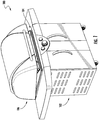
- an embodiment of a gas-fired barbeque grill cooking system 100 includes a base structure 102, a firebox assembly 104 mounted to base structure 102, and a lid assembly 106 movably mounted to base structure 102 to alternately enclose or provide access to firebox assembly 104.
- base structure 102 may be configured as a stationary structure, such as in an outdoor island cooking structure in some embodiments.
- base structure 102 includes a wheeled base 108 from which vertical frame members 111-114 extend.
- Opposing side panels 116 and 118, as well as rear panel 120 (one or more of which may be louvered), are mounted to corresponding ones of the frame members to form an enclosure.
- the enclosure may be configured to store a gas tank (not shown).
- a horizontal frame member 122 extends between frame members 111 and 112 to define an opening 124.
- Door panels 126 and 128 are hingedly mounted to frame members 111 and 112, respectively, to provide access to an interior of the enclosure via opening 124.
- Firebox assembly 104 incorporates a firebox 130 that is configured to mount therein a burner assembly 132 (described later).
- Firebox 130 can be constructed of steel, aluminum, or other heat resistant material.
- a grease catchment 140 is provided at a bottom 142 of firebox 130 to receive grease and/or other droppings from food items that are being cooked within the firebox.
- a bottom 144 of grease catchment 140 is downwardly inclined toward exit apertures (e.g., exit aperture 146), which are configured to permit grease to flow into a removable bin 148.
- Trim panels are mounted to the exterior of firebox 130, including side trim panels 152 and 154, rear trim panel 156, and control panel 158.
- control panel 158 locates a control actuator 160 of a control valve assembly (shown and described later).
- Firebox assembly 104 is mounted to base structure 102 via brackets 162 and 164.
- an optional louvered rear panel 166 is depicted, as well as optional side shelves 168 and 170, which extend from side trim panels 152 and 154, respectively.
- a burner shield 172 is mounted between burner assembly 132 and a cooking grate assembly 174.
- cooking grate assembly 174 incorporates a removable grate portion 176, which is circular in configuration to accommodate placement of a cooking pot and/or pan, for example.
- burner assembly 180 includes a central burner tube 182 flanked by burner tubes 184 and 186.
- central burner tube 182 incorporates a circular configuration and constitutes a first cooking zone, with burner tubes 184 and 186 being generally elongate and constituting one or more additional cooking zones.
- burner tubes 184 and 186 may be configured to receive gas simultaneously, in which case burner tubes 184 and 186 constitute a second cooking zone.
- burner tubes 184 and 186 may be configured to receive gas independently, in which case burner tubes 184 and 186 constitute second and third cooking zones, respectively.
- Burner assembly communicates with a gas control valve 200 of a gas control assembly 202 to receive a flow of gas.
- a regulated flow of gas is provided to gas control valve 200 by a conduit 204.
- the regulated flow of gas may be provided to conduit 204 from a gas tank via a pressure regulator (both of which are not depicted).
- Distribution of the flow of gas to and among the burner tubes of burner assembly 180 is controlled by operation of gas control valve 200.
- gas control valve 200 is configured to supply gas selectively to each of the cooking zones (e.g., to the first cooking zone but not to the second cooking zone).
- gas control valve 200 also is configured to control flame height (via gas flow rate regulation) of the cooking zones either simultaneously or independently by zone.
- burner assembly 210 includes a central burner tube 211, which incorporates a generally circular intermediate portion 212 extending between end portions (e.g., end portion 213).
- Central burner tube 211 is flanked by arcuate-shaped burner tubes 214 and 216 on one side, and arcuate-shaped burner tubes 215 and 217 on the other side.
- the arcuate-shaped burner tubes are curved toward central burner tube 211.
- Central burner tube 211 constitutes a first cooking zone.
- Burner tubes 214 and 215 constitute a second cooking zone, and burner tubes 216 and 217 constitute a third cooking zone.
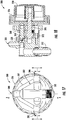
- each of the cooking zones is able to receive gas independently owing to the configuration of gas control valve 220 of a gas control assembly 222.
- gas control valve 220 is configured to provide gas selectively to each of the first, second and/or third cooking zones so that one or more of the cooking zones may be receiving a flow of gas at any given time.
- gas control valve 220 Operation of gas control valve 220 is facilitated by a control actuator 224, which is configured as a rotatable selector ring 226 coaxially mounted about a rotatable control knob 228.
- control actuator 224 configured as a rotatable selector ring 226 coaxially mounted about a rotatable control knob 228.
- rotation of selector ring 226 selects which among the zones is to receive gas, while rotation of control knob 228 adjusts a flow rate of gas through gas control valve 220 to the selected zone(s).
- Burner shield assembly 250 includes multiple shield segments (or "tents"), formed from metal, ceramic, or other heat resistant and heat radiating material.
- the shield segments prevent grease from impinging on the burner tubes.
- each of the shield segments may be generally V-shaped, with the apex being rounded in some embodiments.
- Each shield segment is aligned over a corresponding burner tube and extends lengthwise, spanning the firebox.
- shield segment 252 is positioned in an overlying relationship with burner tube 212
- shield segment 254 is positioned in an overlying relationship with burner tube 214
- shield segment 255 is positioned in an overlying relationship with burner tube 215
- shield segment 256 is positioned in an overlying relationship with burner tube 216
- shield segment 257 is positioned in an overlying relationship with burner tube 217.
- shield segment 252 incorporates a generally circular intermediate portion 258 that corresponds to intermediate portion 212 of central burner tube 211.
- cooking grate assembly 260 incorporates a grate section 262 that defines a circular aperture 264, which is adapted to receive a cooking pot or pan.
- a conformal grate section 266 is sized and shaped to be received within the opening formed by aperture 264.
- a set of tabs are provided on an underside 268 of grate section 262 that extend inwardly from aperture 264.
- the tabs e.g., tab 270
- intermediate portion 212 of central burner tube 211 and intermediate portion 258 of shield segment 252 are configured to improve heat distribution for cooking in the vicinity of grate section 266.
- removable side grate sections 272 and 274 are provided at opposing side edges of grate section 266.
- Grate sections are primarily formed of separated rods or bars for forming a cooking surface.
- grate section 266 incorporates a central flattened plate 276.
- gas control valve 300 incorporates a manifold 302, which includes an inlet port 304.
- Inlet port 304 internally communicates with outlet ports 306, 308 and 310.
- An inlet fitting 312 also is provided for interconnecting inlet port 304 with a supply of gas.
- Manifold 302 defines valve receptacles 316, 318 and 320, which correspond to outlet ports 306, 308 and 310, respectively.
- Each of the valve receptacles is configured to receive a corresponding valve head, which is rotatably disposed within one of the valve receptacles.
- valve head 326 is disposed within valve receptacle 316
- valve head 328 is disposed within valve receptacle 318
- valve head 330 is disposed within valve receptacle 320.
- Each valve head incorporates a gas flow passage and a mating feature (e.g., a slot).
- valve head 326 incorporates a gas flow passage 332 (which extends from a bottom of the valve head through a sidewall) and a mating feature 334.
- the mating features are disposed at the ends of the valve heads (i.e., distal ends) that extend outwardly from manifold 302.
- Biasing members e.g., springs
- Biasing members are positioned to engage between the valve heads and a backing plate 342 to urge the valve heads to seat within the corresponding receptacles.
- biasing member 336 is disposed about valve head 326
- biasing member 338 is disposed about valve head 328
- biasing member 340 is disposed about valve head 330.
- Backing plate 342 includes through-holes that are configured for receiving the proximal ends of actuator rods, which are configured to engage corresponding valve heads.
- through-hole 346 is configured to receive the proximal end of actuator rod 356, through-hole 348 is configured to receive the proximal end of actuator rod 358, and through-hole 350 is configured to receive the proximal end of actuator rod 360.
- the proximal ends of the actuator rods incorporate mating features that are complementary to the mating features of the valve heads so that each of the valve heads matingly engages a corresponding one of the actuator rods.
- valve head 326 engages actuator rod 356, valve head 328 engages actuator rod 358, and valve head 330 engages actuator rod 360.
- the mating features of the valve heads are configured as slots and the complementary mating features of the actuator rods are flattened ends, whereas in other embodiments the complementary mating features of the actuator rods are configured as slots and the valve heads incorporate flattened ends.
- Each of the actuator rods extends lengthwise from a proximal end, which incorporates the complementary mating feature, and a distal end that is configured to engage a corresponding satellite (secondary) gear.
- actuator rod 356 engages satellite gear 366
- actuator rod 358 engages satellite gear 368
- actuator rod 360 engages satellite gear 370.
- the satellite gears are selectively engaged and rotatable in response to rotation of a primary (central) gear 372, which is rotated by control actuator 224.
- Each of the actuator rods incorporates a flange that limits travel of the actuator rod through the corresponding through-hole.
- Each flange also incorporates a protrusion, which is configured to engage rotational stops that limit rotation of the actuator rod about its longitudinal axis, thereby setting rotational limits of the associated valve heads to adjust gas flow rates.
- actuator rod 356 incorporates a flange 362 that limits travel through through-hole 346, with flange 362 including a protrusion 364, which is configured to engage rotational stops 374 and 375.
- the stops are formed by end surfaces of an upwardly protruding ridge 373 that extends about a portion of the through-hole.
- Each of the satellite gears is carried by a corresponding shaft that is received within a corresponding through-hole of a face plate.
- satellite gear 366 is carried by shaft 376, which is received within through-hole 386 of face plate 387
- satellite gear 368 is carried by shaft 378, which is received within through-hole 388
- satellite gear 370 is carried by shaft 380, which is received within through-hole 390.
- Distal ends of the shafts that carry the satellite gears (for example, distal end 392 of shaft 386) extend upwardly beyond upper surface 394 of face plate 387.
- Central shaft 395 which carries central gear 372, also extends upwardly beyond upper surface 394 of face plate 387 after passing through through-hole 396.
- a key 398 retains central shaft 395 in position by engaging within an annular recess 400.
- spacers extend between face plate 387 and backing plate 342 to maintain a desired spacing therebetween.
- Biasing members e.g., biasing member 404 are disposed between the shafts and the actuator rods to urge the shafts upwardly along their longitudinal axes so that the shafts are biased to protrude upwardly through the through-holes. Downward movement of the shafts is selectively provided by a cam 410 ( FIG. 14 ) which is carried by selector ring 226 of control actuator 224.
- control actuator 224 may be further rotated to a second position (e.g., a 1 ⁇ 4 rotation from the first position), which additionally directs a flow of gas to the second zone.
- the second zone includes burner tubes 214 and 215.
- the user may also choose to additionally activate the third zone (which includes burner tubes 216 and 217) by further rotating control actuator 224 to a third position (e.g., a 1 ⁇ 4 rotation from the second position).
Landscapes
- Engineering & Computer Science (AREA)
- Food Science & Technology (AREA)
- Chemical & Material Sciences (AREA)
- Combustion & Propulsion (AREA)
- Mechanical Engineering (AREA)
- General Engineering & Computer Science (AREA)
- Baking, Grill, Roasting (AREA)
Claims (10)
- Gasgrillsystem (100), Folgendes umfassend:einen Feuerraum (130);eine Brenneranordnung (132, 180, 210), die im Feuerraum (130) montiert ist, wobei die Brenneranordnung (132, 180, 210) einen ersten Stabbrenner (184, 186, 214, 215, 216, 217), der einen ersten Kochbereich definiert, und einen zweiten Stabbrenner (184, 186, 214, 215, 216, 217), der einen zweiten Kochbereich definiert, aufweist; undeine Gassteuerungsanordnung (202, 222), die ein Gassteuerungsventil (200, 220, 300) und ein Steuerungsstellglied (160, 224) aufweist, wobei das Gassteuerungsventil (200, 220, 300) dazu ausgelegt ist, als Reaktion auf das Anordnen des Steuerungsstellglieds (160, 224) eine erste Gasströmung zum ersten Stabbrenner (184, 186, 214, 215, 216, 217) und eine zweite Gasströmung zum zweiten Stabbrenner (184, 186, 214, 215, 216, 217) selektiv zu steuern, sodass der erste Kochbereich und der zweite Kochbereich dazu funktionsfähig sind, in einem ersten Modus, in dem nur der erste Kochbereich oder der zweite Kochbereich beheizt wird, unabhängig beheizt zu werden, und in einem zweiten Modus gleichzeitig beheizt zu werden, und dadurch gekennzeichnet, dassdas Steuerungsstellglied (160, 224) einen Drehregler (228) und einen Auswahlring (226) umfasst, die jeweils um eine gemeinsame Achse drehbar sind;der Auswahlring (226) dazu ausgelegt ist, über eine Drehung den ersten Stabbrenner (184, 186, 214, 215, 216, 217) und/oder den zweiten Stabbrenner (184, 186, 214, 215, 216, 217) zu bestimmen, eine zugehörige Gasströmung aufzunehmen; undder Drehregler (228) dazu ausgelegt ist, eine Gasströmungsgeschwindigkeit zum durch den Auswahlring (226) bestimmten ersten Stabbrenner (184, 186, 214, 215, 216, 217) und/oder zweiten Stabbrenner (184, 186, 214, 215, 216, 217) einzustellen.
- System (100) nach Anspruch 1, wobei das Gassteuerungsventil (200, 220, 300) ein primäres Zahnrad (366, 368, 370) und ein sekundäres Zahnrad (366, 368, 370) aufweist, wobei das primäre Zahnrad (366, 368, 370) dazu ausgelegt ist, über den Drehregler (228) gedreht zu werden, wobei das primäre Zahnrad (366, 368, 370) als Reaktion auf die Drehung des Auswahlrings (226) selektiv in das sekundäre Zahnrad (366, 368, 370) eingreift.
- System (100) nach Anspruch 2, wobei:das Gassteuerungsventil (200, 220, 300) einen Ventilkopf (326, 328, 330) aufweist, der einen Gasströmungsweg (332) dort hindurch definiert;der Ventilkopf (326, 328, 330) dazu ausgelegt ist, sich als Reaktion auf das Drehen des sekundären Zahnrads (366, 368, 370) zu drehen.
- System (100) nach Anspruch 1, wobei:das System (100) ferner eine Grillrostanordnung (174, 260) umfasst, die über der Brenneranordnung (132, 180, 210) angeordnet ist; unddie Grillrostanordnung (174, 260) einen Rostabschnitt (262, 266, 272, 274), der eine Öffnung (264) definiert, und einen herausnehmbaren Rostabschnitt (262, 266, 272, 274), der dazu ausgelegt ist, innerhalb der Öffnung (264) aufgenommen zu werden, aufweist.
- System (100) nach Anspruch 4, wobei der herausnehmbare Rostabschnitt (262, 266, 272, 274) eine Mittelplatte (276) aufweist.
- System (100) nach Anspruch 4, wobei:der erste Stabbrenner (184, 186, 214, 215, 216, 217) einen Zwischenabschnitt (212, 258) in einer im Allgemeinen kreisförmigen Konfiguration aufweist unddie Öffnung (264) des Rostabschnitts (262, 266, 272, 274) über dem Zwischenabschnitt (212, 258) des ersten Stabbrenners (184, 186, 214, 215, 216, 217) angeordnet ist.
- System (100) nach Anspruch 1, ferner eine Brennerabschirmungsanordnung (250) umfassend, die über der Brenneranordnung (132, 180, 210) angeordnet ist, wobei die Brennerabschirmungsanordnung (250) ein erstes Abschirmungssegment (252, 254, 255, 256, 257), das über dem ersten Stabbrenner (184, 186, 214, 215, 216, 217) angeordnet ist, und ein zweites Abschirmungssegment (252, 254, 255, 256, 257), das über dem zweiten Stabbrenner (184, 186, 214, 215, 216, 217) angeordnet ist, aufweist.
- System (100) nach Anspruch 7, wobei:der erste Stabbrenner (184, 186, 214, 215, 216, 217) einen Zwischenabschnitt (212, 258) in einer im Allgemeinen kreisförmigen Konfiguration aufweist unddas erste Abschirmungssegment (252, 254, 255, 256, 257) einen Zwischenabschnitt (212, 258) in einer im Allgemeinen kreisförmigen Konfiguration aufweist, der mit dem Zwischenabschnitt (212, 258) des ersten Stabbrenners (184, 186, 214, 215, 216, 217) ausgerichtet ist.
- System (100) nach Anspruch 7, wobei das erste Abschirmungssegment (252, 254, 255, 256, 257) einen V-förmigen Querschnitt aufweist und wobei der Scheitel des Querschnitts abgerundet ist.
- System (100) nach einem der vorstehenden Ansprüche, wobei:das Gassteuerungsventil (200, 220, 300) einen Verteiler (302), einen ersten Ventilkopf (326, 328, 330), einen zweiten Ventilkopf (326, 328, 330), ein primäres Zahnrad (366, 368, 370), ein erstes sekundäres Zahnrad (366, 368, 370) und ein zweites sekundäres Zahnrad (366, 368, 370) aufweist;der Verteiler (302) eine erste Ventilaufnahme (316, 318, 320), eine zweite Ventilaufnahme (316, 318, 320) und einen ersten Einlassanschluss 304, einen ersten Auslassanschluss (306, 308, 310) und einen zweiten Auslassanschluss (306, 308, 310) aufweist, wobei der Einlassanschluss (304) mit dem ersten Auslassanschluss (306, 308, 310) und dem zweiten Auslassanschluss (306, 308, 310) in Fluidverbindung steht;der erste Ventilkopf (326, 328, 330), der sich in die erste Ventilaufnahme (316, 318, 320) erstreckt, einen ersten dort hindurch ausgebildeten Gasströmungsdurchgang (332) aufweist, wobei der zweite Ventilkopf (326, 328, 330), der sich in die zweite Ventilaufnahme (316, 318, 320) erstreckt, einen zweiten dort hindurch ausgebildeten Gasströmungsdurchgang (332) aufweist;der erste Ventilkopf (326, 328, 330) dazu ausgelegt ist, sich als Reaktion auf die Drehung des ersten sekundären Zahnrads (366, 368, 370) zu drehen, wobei der zweite Ventilkopf (326, 328, 330) dazu ausgelegt ist, sich als Reaktion auf die Drehung des zweiten sekundären Zahnrads (366, 368, 370) zu drehen;das primäre Zahnrad (366, 368, 370) dazu ausgelegt ist, selektiv in das erste sekundäre Zahnrad (366, 368, 370) und/oder das zweite sekundäre Zahnrad (366, 368, 370) einzugreifen.
Applications Claiming Priority (1)
| Application Number | Priority Date | Filing Date | Title |
|---|---|---|---|
| US201862657295P | 2018-04-13 | 2018-04-13 |
Publications (2)
| Publication Number | Publication Date |
|---|---|
| EP3552528A1 EP3552528A1 (de) | 2019-10-16 |
| EP3552528B1 true EP3552528B1 (de) | 2021-03-31 |
Family
ID=66175238
Family Applications (1)
| Application Number | Title | Priority Date | Filing Date |
|---|---|---|---|
| EP19168933.0A Active EP3552528B1 (de) | 2018-04-13 | 2019-04-12 | Gasgrill |
Country Status (2)
| Country | Link |
|---|---|
| US (1) | US20190313849A1 (de) |
| EP (1) | EP3552528B1 (de) |
Cited By (2)
| Publication number | Priority date | Publication date | Assignee | Title |
|---|---|---|---|---|
| US12035725B2 (en) | 2022-12-12 | 2024-07-16 | Sharkninja Operating, Llc | Grill systems |
| US12070042B2 (en) | 2022-12-12 | 2024-08-27 | Sharkninja Operating Llc | Grill systems |
Families Citing this family (6)
| Publication number | Priority date | Publication date | Assignee | Title |
|---|---|---|---|---|
| US11213166B2 (en) * | 2019-06-17 | 2022-01-04 | Revoace Inc. Limited | Barbecue grill with a bowl connected to a support structure in a detachable manner |
| ES2961361T3 (es) | 2020-05-12 | 2024-03-11 | Otto Wilde Grillers Gmbh | Parrilla de gas y método de control de esta |
| US11940158B2 (en) | 2021-04-16 | 2024-03-26 | Weber-Stephen Products Llc | Dual-burner assemblies for cookboxes of gas grills |
| US12408793B2 (en) | 2021-09-10 | 2025-09-09 | Weber-Stephen Products Llc | Methods and apparatus for automating shutdown processes of gas grills |
| CN114343448B (zh) * | 2021-12-02 | 2024-05-24 | 永康市东街五金机械有限公司 | 一种固气双燃料型烟熏烤炉 |
| US20230280038A1 (en) * | 2022-02-23 | 2023-09-07 | W.C. Bradley Co. | Burner system for advanced grill |
Family Cites Families (12)
| Publication number | Priority date | Publication date | Assignee | Title |
|---|---|---|---|---|
| US1395799A (en) * | 1919-03-21 | 1921-11-01 | Emil L Claus | Combined burner structure for gas-stoves |
| US2008911A (en) * | 1932-07-18 | 1935-07-23 | Quincy Stove Mfg Co | Dial control for multiple gas cocks |
| US2106310A (en) * | 1935-03-09 | 1938-01-25 | Warrick Jane Elizabeth | Valve |
| US5490452A (en) * | 1994-08-12 | 1996-02-13 | Weber-Stephen Products Co. | Cooking grate assembly for barbecue grills |
| CA2150768A1 (en) * | 1995-06-01 | 1996-12-02 | Wolfgang Schroeter | Gas barbecue |
| CA2158673C (en) * | 1995-09-20 | 2000-11-21 | William Home | Outdoor full function cooking appliance |
| US6705307B2 (en) * | 2002-05-15 | 2004-03-16 | Weber-Stephens Product Co. | Removable gas burner unit for barbecue grill |
| US7096887B2 (en) * | 2004-02-13 | 2006-08-29 | Mueller Industries, Inc. | Fluid valve |
| US8033279B2 (en) * | 2008-11-25 | 2011-10-11 | General Electric Company | Burner control system for a cooking appliance |
| US20100252020A1 (en) * | 2009-04-01 | 2010-10-07 | Alex Siow | Two ring grill burner and control valve |
| US8297317B2 (en) * | 2010-01-21 | 2012-10-30 | Lincoln Brass Works, Inc. | Gas valve with dual outlets |
| US20190093885A1 (en) * | 2017-09-25 | 2019-03-28 | Weber-Stephen Products Llc | Single valve for gas grill with multiple burners |
-
2019
- 2019-04-12 US US16/382,451 patent/US20190313849A1/en not_active Abandoned
- 2019-04-12 EP EP19168933.0A patent/EP3552528B1/de active Active
Non-Patent Citations (1)
| Title |
|---|
| None * |
Cited By (2)
| Publication number | Priority date | Publication date | Assignee | Title |
|---|---|---|---|---|
| US12035725B2 (en) | 2022-12-12 | 2024-07-16 | Sharkninja Operating, Llc | Grill systems |
| US12070042B2 (en) | 2022-12-12 | 2024-08-27 | Sharkninja Operating Llc | Grill systems |
Also Published As
| Publication number | Publication date |
|---|---|
| US20190313849A1 (en) | 2019-10-17 |
| EP3552528A1 (de) | 2019-10-16 |
Similar Documents
| Publication | Publication Date | Title |
|---|---|---|
| EP3552528B1 (de) | Gasgrill | |
| US7527495B2 (en) | Cooperating bridge burner system | |
| US10816215B2 (en) | Diffusion cap burner for gas cooking appliance | |
| US6851420B2 (en) | Burner with piloting ports | |
| EP2337999B1 (de) | Barbecue-grill mit abschnitt zum scharfen anbraten | |
| CA2618038C (en) | Double flame perimeter burner | |
| US6314868B1 (en) | Direct and indirect outdoor cooker | |
| EP2232149B1 (de) | Kopfbrenner und herd damit | |
| JP5313306B2 (ja) | ガスコンロ用グリル装置 | |
| EP2964063B1 (de) | Mehrrohriger brenner mit dünnem profil für gasgrill | |
| US20180160849A1 (en) | Portable multi-function cooking system | |
| WO2005092163A1 (en) | Mobile apparatus provided with a surface for cooking by contact | |
| US6903309B2 (en) | Cooking appliance having concealed cooking feature | |
| US20100282237A1 (en) | Front controls for gas cooking range | |
| MXPA06009873A (es) | Plancha de coccion de combustion a gas. | |
| EP0676591B1 (de) | Kochmulde mit positionierbarem Gasbrenner | |
| US20190167035A1 (en) | Double rotating portable barbecue grill | |
| US20090283090A1 (en) | Hot Top With Dual Burners | |
| US20100147283A1 (en) | Remote oven valve actuator | |
| EP1994827A1 (de) | Backofen | |
| US6622716B2 (en) | Grill heat miser | |
| CN217178591U (zh) | 燃气灶以及用于燃气灶的燃烧器 | |
| CN119042628B (zh) | 一种燃烧器以及灶具 | |
| US20260096687A1 (en) | Griddle system with cook pan arrangement | |
| US20260098645A1 (en) | Griddle and stand system |
Legal Events
| Date | Code | Title | Description |
|---|---|---|---|
| PUAI | Public reference made under article 153(3) epc to a published international application that has entered the european phase |
Free format text: ORIGINAL CODE: 0009012 |
|
| STAA | Information on the status of an ep patent application or granted ep patent |
Free format text: STATUS: THE APPLICATION HAS BEEN PUBLISHED |
|
| AK | Designated contracting states |
Kind code of ref document: A1 Designated state(s): AL AT BE BG CH CY CZ DE DK EE ES FI FR GB GR HR HU IE IS IT LI LT LU LV MC MK MT NL NO PL PT RO RS SE SI SK SM TR |
|
| AX | Request for extension of the european patent |
Extension state: BA ME |
|
| STAA | Information on the status of an ep patent application or granted ep patent |
Free format text: STATUS: REQUEST FOR EXAMINATION WAS MADE |
|
| 17P | Request for examination filed |
Effective date: 20200127 |
|
| RBV | Designated contracting states (corrected) |
Designated state(s): AL AT BE BG CH CY CZ DE DK EE ES FI FR GB GR HR HU IE IS IT LI LT LU LV MC MK MT NL NO PL PT RO RS SE SI SK SM TR |
|
| STAA | Information on the status of an ep patent application or granted ep patent |
Free format text: STATUS: EXAMINATION IS IN PROGRESS |
|
| 17Q | First examination report despatched |
Effective date: 20200602 |
|
| GRAP | Despatch of communication of intention to grant a patent |
Free format text: ORIGINAL CODE: EPIDOSNIGR1 |
|
| STAA | Information on the status of an ep patent application or granted ep patent |
Free format text: STATUS: GRANT OF PATENT IS INTENDED |
|
| INTG | Intention to grant announced |
Effective date: 20201022 |
|
| GRAS | Grant fee paid |
Free format text: ORIGINAL CODE: EPIDOSNIGR3 |
|
| GRAA | (expected) grant |
Free format text: ORIGINAL CODE: 0009210 |
|
| STAA | Information on the status of an ep patent application or granted ep patent |
Free format text: STATUS: THE PATENT HAS BEEN GRANTED |
|
| AK | Designated contracting states |
Kind code of ref document: B1 Designated state(s): AL AT BE BG CH CY CZ DE DK EE ES FI FR GB GR HR HU IE IS IT LI LT LU LV MC MK MT NL NO PL PT RO RS SE SI SK SM TR |
|
| REG | Reference to a national code |
Ref country code: GB Ref legal event code: FG4D Ref country code: CH Ref legal event code: EP |
|
| REG | Reference to a national code |
Ref country code: AT Ref legal event code: REF Ref document number: 1375966 Country of ref document: AT Kind code of ref document: T Effective date: 20210415 |
|
| REG | Reference to a national code |
Ref country code: DE Ref legal event code: R096 Ref document number: 602019003521 Country of ref document: DE |
|
| REG | Reference to a national code |
Ref country code: IE Ref legal event code: FG4D |
|
| RAP2 | Party data changed (patent owner data changed or rights of a patent transferred) |
Owner name: LANDMANN GERMANY GMBH |
|
| REG | Reference to a national code |
Ref country code: LT Ref legal event code: MG9D |
|
| PG25 | Lapsed in a contracting state [announced via postgrant information from national office to epo] |
Ref country code: BG Free format text: LAPSE BECAUSE OF FAILURE TO SUBMIT A TRANSLATION OF THE DESCRIPTION OR TO PAY THE FEE WITHIN THE PRESCRIBED TIME-LIMIT Effective date: 20210630 Ref country code: FI Free format text: LAPSE BECAUSE OF FAILURE TO SUBMIT A TRANSLATION OF THE DESCRIPTION OR TO PAY THE FEE WITHIN THE PRESCRIBED TIME-LIMIT Effective date: 20210331 Ref country code: HR Free format text: LAPSE BECAUSE OF FAILURE TO SUBMIT A TRANSLATION OF THE DESCRIPTION OR TO PAY THE FEE WITHIN THE PRESCRIBED TIME-LIMIT Effective date: 20210331 Ref country code: NO Free format text: LAPSE BECAUSE OF FAILURE TO SUBMIT A TRANSLATION OF THE DESCRIPTION OR TO PAY THE FEE WITHIN THE PRESCRIBED TIME-LIMIT Effective date: 20210630 |
|
| REG | Reference to a national code |
Ref country code: DE Ref legal event code: R081 Ref document number: 602019003521 Country of ref document: DE Owner name: LANDMANN GERMANY GMBH, DE Free format text: FORMER OWNER: LANDMANN GMBH & CO. HANDELS-KG, 27711 OSTERHOLZ-SCHARMBECK, DE |
|
| PG25 | Lapsed in a contracting state [announced via postgrant information from national office to epo] |
Ref country code: LV Free format text: LAPSE BECAUSE OF FAILURE TO SUBMIT A TRANSLATION OF THE DESCRIPTION OR TO PAY THE FEE WITHIN THE PRESCRIBED TIME-LIMIT Effective date: 20210331 Ref country code: RS Free format text: LAPSE BECAUSE OF FAILURE TO SUBMIT A TRANSLATION OF THE DESCRIPTION OR TO PAY THE FEE WITHIN THE PRESCRIBED TIME-LIMIT Effective date: 20210331 Ref country code: SE Free format text: LAPSE BECAUSE OF FAILURE TO SUBMIT A TRANSLATION OF THE DESCRIPTION OR TO PAY THE FEE WITHIN THE PRESCRIBED TIME-LIMIT Effective date: 20210331 |
|
| REG | Reference to a national code |
Ref country code: NL Ref legal event code: MP Effective date: 20210331 |
|
| REG | Reference to a national code |
Ref country code: AT Ref legal event code: MK05 Ref document number: 1375966 Country of ref document: AT Kind code of ref document: T Effective date: 20210331 |
|
| PG25 | Lapsed in a contracting state [announced via postgrant information from national office to epo] |
Ref country code: LT Free format text: LAPSE BECAUSE OF FAILURE TO SUBMIT A TRANSLATION OF THE DESCRIPTION OR TO PAY THE FEE WITHIN THE PRESCRIBED TIME-LIMIT Effective date: 20210331 Ref country code: CZ Free format text: LAPSE BECAUSE OF FAILURE TO SUBMIT A TRANSLATION OF THE DESCRIPTION OR TO PAY THE FEE WITHIN THE PRESCRIBED TIME-LIMIT Effective date: 20210331 Ref country code: EE Free format text: LAPSE BECAUSE OF FAILURE TO SUBMIT A TRANSLATION OF THE DESCRIPTION OR TO PAY THE FEE WITHIN THE PRESCRIBED TIME-LIMIT Effective date: 20210331 Ref country code: AT Free format text: LAPSE BECAUSE OF FAILURE TO SUBMIT A TRANSLATION OF THE DESCRIPTION OR TO PAY THE FEE WITHIN THE PRESCRIBED TIME-LIMIT Effective date: 20210331 Ref country code: SM Free format text: LAPSE BECAUSE OF FAILURE TO SUBMIT A TRANSLATION OF THE DESCRIPTION OR TO PAY THE FEE WITHIN THE PRESCRIBED TIME-LIMIT Effective date: 20210331 Ref country code: NL Free format text: LAPSE BECAUSE OF FAILURE TO SUBMIT A TRANSLATION OF THE DESCRIPTION OR TO PAY THE FEE WITHIN THE PRESCRIBED TIME-LIMIT Effective date: 20210331 |
|
| PG25 | Lapsed in a contracting state [announced via postgrant information from national office to epo] |
Ref country code: PT Free format text: LAPSE BECAUSE OF FAILURE TO SUBMIT A TRANSLATION OF THE DESCRIPTION OR TO PAY THE FEE WITHIN THE PRESCRIBED TIME-LIMIT Effective date: 20210802 Ref country code: RO Free format text: LAPSE BECAUSE OF FAILURE TO SUBMIT A TRANSLATION OF THE DESCRIPTION OR TO PAY THE FEE WITHIN THE PRESCRIBED TIME-LIMIT Effective date: 20210331 Ref country code: SK Free format text: LAPSE BECAUSE OF FAILURE TO SUBMIT A TRANSLATION OF THE DESCRIPTION OR TO PAY THE FEE WITHIN THE PRESCRIBED TIME-LIMIT Effective date: 20210331 Ref country code: PL Free format text: LAPSE BECAUSE OF FAILURE TO SUBMIT A TRANSLATION OF THE DESCRIPTION OR TO PAY THE FEE WITHIN THE PRESCRIBED TIME-LIMIT Effective date: 20210331 Ref country code: IS Free format text: LAPSE BECAUSE OF FAILURE TO SUBMIT A TRANSLATION OF THE DESCRIPTION OR TO PAY THE FEE WITHIN THE PRESCRIBED TIME-LIMIT Effective date: 20210731 |
|
| PG25 | Lapsed in a contracting state [announced via postgrant information from national office to epo] |
Ref country code: LU Free format text: LAPSE BECAUSE OF NON-PAYMENT OF DUE FEES Effective date: 20210412 |
|
| REG | Reference to a national code |
Ref country code: DE Ref legal event code: R097 Ref document number: 602019003521 Country of ref document: DE |
|
| REG | Reference to a national code |
Ref country code: BE Ref legal event code: MM Effective date: 20210430 |
|
| PG25 | Lapsed in a contracting state [announced via postgrant information from national office to epo] |
Ref country code: MC Free format text: LAPSE BECAUSE OF FAILURE TO SUBMIT A TRANSLATION OF THE DESCRIPTION OR TO PAY THE FEE WITHIN THE PRESCRIBED TIME-LIMIT Effective date: 20210331 Ref country code: AL Free format text: LAPSE BECAUSE OF FAILURE TO SUBMIT A TRANSLATION OF THE DESCRIPTION OR TO PAY THE FEE WITHIN THE PRESCRIBED TIME-LIMIT Effective date: 20210331 Ref country code: DK Free format text: LAPSE BECAUSE OF FAILURE TO SUBMIT A TRANSLATION OF THE DESCRIPTION OR TO PAY THE FEE WITHIN THE PRESCRIBED TIME-LIMIT Effective date: 20210331 Ref country code: ES Free format text: LAPSE BECAUSE OF FAILURE TO SUBMIT A TRANSLATION OF THE DESCRIPTION OR TO PAY THE FEE WITHIN THE PRESCRIBED TIME-LIMIT Effective date: 20210331 |
|
| PLBE | No opposition filed within time limit |
Free format text: ORIGINAL CODE: 0009261 |
|
| STAA | Information on the status of an ep patent application or granted ep patent |
Free format text: STATUS: NO OPPOSITION FILED WITHIN TIME LIMIT |
|
| 26N | No opposition filed |
Effective date: 20220104 |
|
| PG25 | Lapsed in a contracting state [announced via postgrant information from national office to epo] |
Ref country code: IE Free format text: LAPSE BECAUSE OF NON-PAYMENT OF DUE FEES Effective date: 20210412 |
|
| PG25 | Lapsed in a contracting state [announced via postgrant information from national office to epo] |
Ref country code: IS Free format text: LAPSE BECAUSE OF FAILURE TO SUBMIT A TRANSLATION OF THE DESCRIPTION OR TO PAY THE FEE WITHIN THE PRESCRIBED TIME-LIMIT Effective date: 20210731 Ref country code: FR Free format text: LAPSE BECAUSE OF NON-PAYMENT OF DUE FEES Effective date: 20210531 |
|
| PG25 | Lapsed in a contracting state [announced via postgrant information from national office to epo] |
Ref country code: IT Free format text: LAPSE BECAUSE OF FAILURE TO SUBMIT A TRANSLATION OF THE DESCRIPTION OR TO PAY THE FEE WITHIN THE PRESCRIBED TIME-LIMIT Effective date: 20210331 Ref country code: BE Free format text: LAPSE BECAUSE OF NON-PAYMENT OF DUE FEES Effective date: 20210430 |
|
| PGFP | Annual fee paid to national office [announced via postgrant information from national office to epo] |
Ref country code: DE Payment date: 20220331 Year of fee payment: 4 |
|
| REG | Reference to a national code |
Ref country code: CH Ref legal event code: PL |
|
| PG25 | Lapsed in a contracting state [announced via postgrant information from national office to epo] |
Ref country code: LI Free format text: LAPSE BECAUSE OF NON-PAYMENT OF DUE FEES Effective date: 20220430 Ref country code: CH Free format text: LAPSE BECAUSE OF NON-PAYMENT OF DUE FEES Effective date: 20220430 |
|
| PG25 | Lapsed in a contracting state [announced via postgrant information from national office to epo] |
Ref country code: CY Free format text: LAPSE BECAUSE OF FAILURE TO SUBMIT A TRANSLATION OF THE DESCRIPTION OR TO PAY THE FEE WITHIN THE PRESCRIBED TIME-LIMIT Effective date: 20210331 |
|
| PG25 | Lapsed in a contracting state [announced via postgrant information from national office to epo] |
Ref country code: HU Free format text: LAPSE BECAUSE OF FAILURE TO SUBMIT A TRANSLATION OF THE DESCRIPTION OR TO PAY THE FEE WITHIN THE PRESCRIBED TIME-LIMIT; INVALID AB INITIO Effective date: 20190412 Ref country code: GR Free format text: LAPSE BECAUSE OF FAILURE TO SUBMIT A TRANSLATION OF THE DESCRIPTION OR TO PAY THE FEE WITHIN THE PRESCRIBED TIME-LIMIT Effective date: 20210331 |
|
| REG | Reference to a national code |
Ref country code: DE Ref legal event code: R119 Ref document number: 602019003521 Country of ref document: DE |
|
| GBPC | Gb: european patent ceased through non-payment of renewal fee |
Effective date: 20230412 |
|
| PG25 | Lapsed in a contracting state [announced via postgrant information from national office to epo] |
Ref country code: GB Free format text: LAPSE BECAUSE OF NON-PAYMENT OF DUE FEES Effective date: 20230412 |
|
| PG25 | Lapsed in a contracting state [announced via postgrant information from national office to epo] |
Ref country code: GB Free format text: LAPSE BECAUSE OF NON-PAYMENT OF DUE FEES Effective date: 20230412 Ref country code: DE Free format text: LAPSE BECAUSE OF NON-PAYMENT OF DUE FEES Effective date: 20231103 |
|
| PG25 | Lapsed in a contracting state [announced via postgrant information from national office to epo] |
Ref country code: MK Free format text: LAPSE BECAUSE OF FAILURE TO SUBMIT A TRANSLATION OF THE DESCRIPTION OR TO PAY THE FEE WITHIN THE PRESCRIBED TIME-LIMIT Effective date: 20210331 |
|
| PG25 | Lapsed in a contracting state [announced via postgrant information from national office to epo] |
Ref country code: MT Free format text: LAPSE BECAUSE OF FAILURE TO SUBMIT A TRANSLATION OF THE DESCRIPTION OR TO PAY THE FEE WITHIN THE PRESCRIBED TIME-LIMIT Effective date: 20210331 |
|
| PG25 | Lapsed in a contracting state [announced via postgrant information from national office to epo] |
Ref country code: TR Free format text: LAPSE BECAUSE OF FAILURE TO SUBMIT A TRANSLATION OF THE DESCRIPTION OR TO PAY THE FEE WITHIN THE PRESCRIBED TIME-LIMIT Effective date: 20210331 |