EP3552501B1 - Vorrichtung und verfahren zur inspektion einer stirnfläche eines stabförmigen rauchartikels - Google Patents
Vorrichtung und verfahren zur inspektion einer stirnfläche eines stabförmigen rauchartikels Download PDFInfo
- Publication number
- EP3552501B1 EP3552501B1 EP19165376.5A EP19165376A EP3552501B1 EP 3552501 B1 EP3552501 B1 EP 3552501B1 EP 19165376 A EP19165376 A EP 19165376A EP 3552501 B1 EP3552501 B1 EP 3552501B1
- Authority
- EP
- European Patent Office
- Prior art keywords
- camera
- smoking article
- products
- position sensor
- time
- Prior art date
- Legal status (The legal status is an assumption and is not a legal conclusion. Google has not performed a legal analysis and makes no representation as to the accuracy of the status listed.)
- Active
Links
- 230000000391 smoking effect Effects 0.000 title claims description 75
- 238000000034 method Methods 0.000 title claims description 11
- 238000012545 processing Methods 0.000 claims description 11
- 230000001960 triggered effect Effects 0.000 claims description 9
- 238000011156 evaluation Methods 0.000 claims description 3
- 239000000779 smoke Substances 0.000 claims description 3
- 238000012546 transfer Methods 0.000 description 12
- 238000005259 measurement Methods 0.000 description 11
- 238000006073 displacement reaction Methods 0.000 description 7
- 230000003287 optical effect Effects 0.000 description 7
- 230000004888 barrier function Effects 0.000 description 4
- 238000005286 illumination Methods 0.000 description 4
- 238000007689 inspection Methods 0.000 description 4
- 239000000463 material Substances 0.000 description 4
- 241000208125 Nicotiana Species 0.000 description 3
- 235000002637 Nicotiana tabacum Nutrition 0.000 description 3
- 238000004519 manufacturing process Methods 0.000 description 3
- 235000019504 cigarettes Nutrition 0.000 description 2
- 238000003384 imaging method Methods 0.000 description 2
- 230000003746 surface roughness Effects 0.000 description 2
- 238000011144 upstream manufacturing Methods 0.000 description 2
- QTBSBXVTEAMEQO-UHFFFAOYSA-M Acetate Chemical compound CC([O-])=O QTBSBXVTEAMEQO-UHFFFAOYSA-M 0.000 description 1
- 241000239290 Araneae Species 0.000 description 1
- 238000013459 approach Methods 0.000 description 1
- 238000001816 cooling Methods 0.000 description 1
- 230000001419 dependent effect Effects 0.000 description 1
- 238000011161 development Methods 0.000 description 1
- 230000018109 developmental process Effects 0.000 description 1
- 230000002349 favourable effect Effects 0.000 description 1
- 238000012544 monitoring process Methods 0.000 description 1
- 238000000275 quality assurance Methods 0.000 description 1
- 238000001454 recorded image Methods 0.000 description 1
- 230000000284 resting effect Effects 0.000 description 1
- 230000000717 retained effect Effects 0.000 description 1
- 239000007787 solid Substances 0.000 description 1
- 239000000126 substance Substances 0.000 description 1
- 238000010408 sweeping Methods 0.000 description 1
- 238000011179 visual inspection Methods 0.000 description 1
Images

Classifications
-
- A—HUMAN NECESSITIES
- A24—TOBACCO; CIGARS; CIGARETTES; SIMULATED SMOKING DEVICES; SMOKERS' REQUISITES
- A24C—MACHINES FOR MAKING CIGARS OR CIGARETTES
- A24C5/00—Making cigarettes; Making tipping materials for, or attaching filters or mouthpieces to, cigars or cigarettes
- A24C5/32—Separating, ordering, counting or examining cigarettes; Regulating the feeding of tobacco according to rod or cigarette condition
- A24C5/34—Examining cigarettes or the rod, e.g. for regulating the feeding of tobacco; Removing defective cigarettes
- A24C5/3412—Examining cigarettes or the rod, e.g. for regulating the feeding of tobacco; Removing defective cigarettes by means of light, radiation or electrostatic fields
-
- A—HUMAN NECESSITIES
- A24—TOBACCO; CIGARS; CIGARETTES; SIMULATED SMOKING DEVICES; SMOKERS' REQUISITES
- A24C—MACHINES FOR MAKING CIGARS OR CIGARETTES
- A24C5/00—Making cigarettes; Making tipping materials for, or attaching filters or mouthpieces to, cigars or cigarettes
- A24C5/32—Separating, ordering, counting or examining cigarettes; Regulating the feeding of tobacco according to rod or cigarette condition
- A24C5/34—Examining cigarettes or the rod, e.g. for regulating the feeding of tobacco; Removing defective cigarettes
-
- A—HUMAN NECESSITIES
- A24—TOBACCO; CIGARS; CIGARETTES; SIMULATED SMOKING DEVICES; SMOKERS' REQUISITES
- A24C—MACHINES FOR MAKING CIGARS OR CIGARETTES
- A24C5/00—Making cigarettes; Making tipping materials for, or attaching filters or mouthpieces to, cigars or cigarettes
- A24C5/32—Separating, ordering, counting or examining cigarettes; Regulating the feeding of tobacco according to rod or cigarette condition
- A24C5/322—Transporting cigarettes during manufacturing
- A24C5/326—Transporting cigarettes during manufacturing with lateral transferring means
Definitions
- the present invention relates to a device for inspecting an end face of a rod-shaped smoking article with the features of the preamble of claim 1 and a method for inspecting an end face of a rod-shaped smoking article with the features of the preamble of claim 10.
- Rod-shaped smoking articles are e.g. cigarettes, cigarillos, heat not burn products (HNB products) or similar products which are intended for inhalation by a consumer.
- HNB products heat not burn products
- Rod-shaped smoking articles are also to be understood as preliminary products of smoking articles such as filter rods, tobacco sticks with a tobacco material stabilized in shape by a wrapping strip, segments of HNB products such as tubular cooling sections, taste-influencing segments or the like, which are subsequently combined with other preliminary products to form a finished rod-shaped smoking article get connected.
- the rod-shaped smoking articles and preliminary products of the smoking articles are referred to below in the description as products for the sake of simplicity.
- a conveying device which comprises a format section in which an endless strand of a material, such as a tobacco or tow, is placed on an endless web of a casing material, which is then folded over and glued on the edges of the casing material is fixed to a solid strand.
- This rigid strand is then cut into cylindrical or rod-shaped products with a predetermined rod length by means of a rotating knife carrier with several knives protruding radially on the outside.
- the products are pushed on a guide device as a strand of adjacent individual products in a longitudinally axial transport direction or strand direction to a take-over point or, alternatively, actively transported further.
- the products are conveyed away from the guide device by a longitudinal conveyor and transported to a transfer point, where the products are transferred from the longitudinal conveyor to a transverse conveyor transversely to their longitudinal direction.
- the rigid strand or the strand of adjacent individual products can also be present without wrapping paper, for example for conveying and using non-wrapped acetate filters (NWA filters).
- the longitudinal conveyor is formed by a rotationally driven drum which has a plurality of protruding, rotatably mounted lever arms. On each of the lever arms, one or more axially spaced receptacles are provided, on which one or more grooves or troughs that are aligned parallel to the supplied products and can be acted upon by vacuum are provided.
- the lever arms execute a rotational movement in the opposite direction to the rotational movement of the drum for an outside observer, so that the recordings are guided on an elliptical path of movement.
- the recordings themselves are held in a constant, preferably horizontal orientation by means of a mechanism during the revolving movement of the drum and the lever arms, which is a Alignment of the products held in the receptacles ensured, the longitudinal axes of the products always preferably being parallel to the transport direction of the supplied strand.
- the receptacles with the channels provided are guided past the products at a transfer point so close that the products are sucked in by the negative pressure acting in the channels and conveyed away by the conveyor device.
- the products are moved to a transfer point in which the channels with the products held therein carry out a preferably pure transverse movement to their longitudinal axes or to the transport direction of the guide device.
- a cross conveyor is provided, which is also formed by a drum that can be driven in rotation, but is arranged with its axis of rotation in a preferably right-angled arrangement to the axis of rotation of the longitudinal conveyor.
- a plurality of grooves that can also be subjected to negative pressure and are aligned parallel to the axis of rotation of the transverse conveyor are provided, which at the transfer point are guided past the grooves of the longitudinal conveyor and the products held therein so close that the products are guided across their longitudinal axis are taken over and transported on.
- a problem with the transport of the products is that the grooves of the receptacles of the longitudinal conveyor in the transfer point have to be moved at a higher speed than the speed of the supplied products (also called overspeed) so that the products supplied to the longitudinal conveyor on the guide device in no case can accumulate or collide with the following product during the transfer movement.
- the overspeed is also dependent on the rod length of the products, since the speed of the longitudinal conveyor of the conveying devices is also the same for the transport of products of different rod lengths, and the line speed of the supplied products must be adjusted to a predetermined number of products to be taken over per unit of time. For these reasons, under unfavorable circumstances, the products are taken over at up to twice the overspeed compared to the feed rate of the products.
- the channels themselves also have a certain surface roughness, which helps determine the frictional forces that act between the channels and the products when they are taken over.
- the products are accelerated jerkily when they are taken over, as a result of which certain forces act on the products in the axial and radial directions, which, among other things, are the cause of the head failure of the products.
- the overspeed should therefore generally be as low as possible or only slightly higher than the feed rate of the products.
- the alignment of the products in the grooves of the cross conveyor is particularly important when the products are transported in double length and are cut into single-length products in this position on the cross conveyor, since the position of the products in the grooves of the cross conveyor is at a fixed cutting edge also has a decisive influence on the lengths of the cut, simply long products.
- an end face sensor based on imaging sensors is provided, for example, in filter manufacturing machines.
- the products are typically subjected to an optical inspection by means of a camera which is set up to record images of an end face of the products.
- the images recorded by the camera are then evaluated by an electronic signal processing device.
- a measuring device for on-line measurement is, for example, from EP 2 677 273 B1 known.
- the measuring device is set up for the optical inspection of the end faces of products conveyed in a cross conveyor and, in one embodiment, proposes quality inspection using a digital camera for 2D recordings
- US 2015/0374028 A discloses an apparatus for inspecting the porosity of a rod-shaped smoking article.
- a possible alignment of the products within the troughs of the drum in the axial direction typically takes place towards the center of the delivery drum.
- the distance between the end face of a product and the camera changes when the length of the products changes or the format changes.
- the distance between the camera and the face to be inspected is different than before the length change or the format change, and a valid measurement with the camera is not possible.
- the camera has previously had to be readjusted after each format change.
- An object of the invention is to provide a device and a corresponding method, which an effective and Enable reliable quality assurance through a reliable visual inspection of the products.
- a position sensor directed at a measuring position which generates a signal when the smoking articles are conveyed through the measuring position and forwards it to the camera, and the camera can be triggered and / or moved into a trigger position as a function of the signal from the position sensor is.
- the invention has recognized that the distance between the camera and the smoking article must adhere to a fixed value in order to generate a sufficiently sharp image with the camera for the evaluation. Triggering the camera as a function of the signal from the position sensor ensures that the camera only records images under the condition when the smoking article is in a defined position that corresponds to the measurement position at the time of sensing by the position sensor.
- the signal which indicates that the smoking article is in the measuring position, is then passed on to the camera in order to trigger a recording and / or to create a condition favorable for a recording in which a sharp image can be made.
- the sensing can be implemented in different ways, for example by referencing directly to the smoking article and / or to a machine part coupled to the position of the smoking article becomes.
- the camera can be arranged and / or moved into the trigger position so that the distance between the camera and the smoking article corresponds to the specified distance in order to be able to record a sharp image with the camera.
- Moving to the release position is used to set the exact distance and ensures a sharp image of the face.
- a fluctuation in the position of the smoking article for example when it is taken over, can thus be taken into account when the image is recorded.
- a variation in the length of the smoking article can thus also be compensated for without further effort.
- a manual adjustment of the trigger position to the corresponding length of the smoking article, which is otherwise customary in the prior art, is therefore not necessary, ie the device and the corresponding method according to the invention operate independently of the format.
- the recording of an image by the camera can take place in such a way that the camera ensures the exposure over a certain exposure time, for example in the range of fractions of a second, based on the generated signal, and during the exposure a luminaire illuminates the face to be inspected.
- the lighting means can optionally comprise an LED.
- the duration of the illumination can preferably be shorter than the exposure time.
- the camera triggers a recording of an image of the smoking article detected by the position sensor at the same time as the signal is received, in order to include a sharp image of the smoking article being guided past the position sensor in the case of a distance between the camera and smoking article corresponding to the value specified for a sharp image to be able to record with the camera.
- the smoking article passes the focal plane of the lens at the time the signal is generated of the camera, ie the measuring position lies in the focal plane of the camera or the trigger position is spaced from the measuring position by a value corresponding to the focal plane. A simultaneous triggering of a recording thus produces a sharp image of the sensed or detected smoking article.
- Simultaneous triggering is also to be understood as signal-related time differences, which can result, for example, from the signal line from the position sensor to the camera or from the signal processing in the position sensor and / or the camera and can be, for example, in the range of a few microseconds.
- the electronic signal processing device determines a trigger time of the camera for triggering an image, for example around the arrangement of the position sensor and the camera, as a function of the signal from the position sensor and the time span required for the smoking article to move from the measuring position to the receiving position to be able to locally decouple from one another using the movement of the smoking article and / or the conveying device.
- the smoking article passes the focal plane with a time offset, for example due to the movement of the conveyor device after the point in time of the generation of the signal.
- the camera can be directed to a recording position different from the measurement position, which the smoking article passes at a defined point in time, which enables the camera to be arranged in a manner that can be adapted to the structural circumstances.
- the triggering time is determined in such a way that precisely the smoking article detected by the position sensor moves through the recording position at the triggering time in order to be able to make defined and product-related recordings.
- the trigger time is preferably determined as a function of the movement of the cross conveyor in order to use a defined angular speed or rotational speed of the cross conveyor, which is preferably designed as a drum, for an exact forecast of the movement of the smoking articles in the cross conveyor and thus determine the movement of the smoking articles through the receiving position.
- the optical axis of the camera is preferably parallel to the axis of rotation of the cross conveyor and therefore parallel to the longitudinal axes of the smoking articles conveyed in the cross conveyor.
- the triggering time is advantageously determined as a function of the movement of the smoking article in a transport direction of the smoking article.
- the direction of transport of the smoking article in the guide device is the same as the longitudinal axis of the smoking article conveyed as a strand.
- the triggering time is preferably determined as a function of the transport direction of the smoking article in the guide device or parallel thereto, since the movement of the smoking article in or against the direction of the camera is used, which is the relevant direction for the sharp image of the end face.
- the direction of transport of the smoking articles is perpendicular to their longitudinal axes, and the direction of transport and the position of the smoking articles can be used to determine exactly when the respective products cross the receiving position.
- the position sensor is preferably arranged in such a way that it detects the position of a smoking article which is transported by a longitudinal conveyor which is arranged between the guide device and the transverse conveyor and which can be driven in a rotational movement is in order to be able to take a picture of the smoking article after the smoking article has been taken over by the guide device from the longitudinal conveyor at a takeover point.
- the longitudinal conveyor conveys the smoking articles in and / or parallel to the transport direction or in the longitudinal axial direction of the smoking articles.
- the movement of the longitudinal conveyor can preferably be used to determine the triggering time.
- a product-related image is made of the smoking article sensed by the position sensor after it has assumed an imprecise position in the grooves of the longitudinal conveyor holding the smoking article due to the overspeed.
- the source of error in the transfer of the smoking article is therefore upstream of the measuring position in relation to the transport direction, so that this error is already contained in the detected position of the smoking article and can be compensated for.
- a quality check can be carried out at a defined position before the transfer to the cross conveyor. For example, the transport speed of the longitudinal conveyor in the transport direction can be included in the determination of the triggering time.
- the triggering time is preferably determined as a function of the rotational movement of the longitudinal conveyor.
- the longitudinal conveyor is preferably designed as a drum and performs a rotational movement about an axis of rotation.
- the trigger time is preferably determined taking into account a rotation angle of the longitudinal conveyor resulting from the measuring position and the receiving position in order to make a defined position for the quality check particularly easy and precise to determine based on the dynamics of the longitudinal conveyor.
- the rotation of the longitudinal conveyor through an angle leads to a movement transversely to the transport direction or to the longitudinal axis of the smoking article and allows the camera to be arranged so that its optical axis does not have to be directed towards the guideway.
- the camera can be adapted to the structural conditions and can be arranged with its optical axis parallel to the transport direction of the guideway.
- the trigger time is determined in such a way that at the time the measurement signal is recorded by the position sensor, the time is added which is necessary to move the detected smoking article transported by the longitudinal conveyor from the measurement position to the recording position for the camera to record the image .
- the position sensor is preferably set up to generate the signal when passing the face to be inspected in order to couple the signal directly to the position of the face to be inspected and to be able to record sharp images of this with the camera.
- the camera has a focal plane and can be triggered and / or moved in such a way that the end face to be inspected is in the focal plane or crosses the focal plane for recording an image at a defined point in time.
- the focal plane is a target plane in which the front surface of the product should be, in order to be able to take a sharp picture of the face.
- the camera can be moved in or against the direction of the end face by means of a displacement device in order to be able to set the distance between the camera and the end face, i.e. between the release position and the recording position.
- the direction of displacement of the camera is aligned parallel to the axis of rotation of the cross conveyor, to the direction of the smoking article in the guide device and / or perpendicular to the axis of rotation of the longitudinal conveyor.
- the camera can preferably be adjusted to a focal plane in order to be able to record a sharp image.
- the camera preferably has a zoom object and / or an autofocus.
- the camera has a variable focal plane and the focal plane can be adapted to the determined position of the smoking article in the receiving position by adjusting the camera.
- the position sensor is advantageously an optical displacement sensor in order to be able to determine the distance between the position sensor and smoking article.
- the position sensor preferably comprises a light barrier, and the position sensor is preferably set up to sense a light beam perpendicular to the longitudinal axes of the smoking article in order to pass the smoking article or the end face to be able to sense effectively and easily.
- the signal is generated when a smoking article is detected by a smoking article passing through the light barrier and thereby interrupting the light beam, which means that it does not hit the position sensor for a short time, ie while the smoking article is passing through the measurement position, thereby triggering the signal.
- the light beam is preferably emitted by the position sensor and / or a light transmitting device and the position sensor is preferably designed as a light sensor which is set up to sense the light beam.
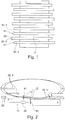
- Figure 1 shows a schematic illustration of a transverse conveyor 2 with smoking articles 5 located therein, which are hereinafter referred to as products 50, and the end faces 51 of the products 50 to be inspected to illustrate the underlying problem.
- the transfer position of the products 50 onto the transverse conveyor 2 depends on various factors, such as, for example, the speed of the products 50 in a longitudinal conveyor 1 shown schematically.
- FIG. 2 a schematic illustration of a device 10 according to an embodiment of the invention is shown, in which a camera 20 is provided, which can be triggered as a function of a signal from a position sensor 13.
- a signal processing device 24 evaluates the images recorded by the camera 20.
- the products 50 are pushed on on a guide device 4 as a strand of individual rods resting against one another in a longitudinally axial transport direction I or strand direction to a take-over point or, alternatively, also actively transported further.
- the transport direction I is preferably defined by the guide device 4.
- the products 50 are conveyed away by the guide device 4 with a longitudinal conveyor 1, which is only shown schematically in the form of ellipses and is designed as a drum, which is also referred to as a spider in the applicant's home.
- the products 50 are in that Longitudinal conveyor 1 is held in receptacles, which are not shown, for example, arranged on lever arms, and the longitudinal conveyor executes a rotational movement about an axis of rotation oriented perpendicular to the transport direction I.
- the receptacles preferably maintain a constant, preferably horizontal alignment during the circulating movement of the longitudinal conveyor 1, which ensures a constant, preferably horizontal alignment of the products 50 during the conveyance in the longitudinal conveyor 1.
- the lever arms move in such a way that the products 50 describe an elliptical path as they are conveyed by the longitudinal conveyor 1.
- the products 50 are always preferably aligned parallel to the transport direction I in the guide device 4 and in the receptacles of the longitudinal conveyor 1.
- the rotational movement of the longitudinal conveyor 1 causes the products 50 to be transported perpendicularly or transversely to the supplied transport direction I; the longitudinal axis of the products is always aligned in the direction of transport I.
- This transverse movement can, however, be neglected by a suitable arrangement of the camera 20, a correspondingly large selected image area and / or a displacement of a region of interest (ROI) defined in the image.
- ROI region of interest
- the product 50 moves as in FIG Figure 2 shown, due to the movement in the guide device 4 through a measuring position II, the position sensor 13 being set up to detect the products 50 in the measuring position II.
- the measuring position II can also be selected such that the product 50 passes the measuring position II due to the movement of the longitudinal conveyor 1.
- the actual position of the end face 51 after the transfer to the longitudinal conveyor 1 is then detected, for example by means of a light barrier of the position sensor 13.
- the position sensor 13 If the product 50 passes the measuring position II, the position sensor 13 generates the signal and forwards it to the signal processing device 24.
- the position sensor 13 is a light barrier that is set up to emit or feed a light beam perpendicular to the transport direction I. to sense.
- the product 50 fed by the conveyor 4 in the transport direction 1 first passes the light beam of the position sensor 13 with an end face 51 to be inspected, which allows an exact assessment of the further trajectory of the end face 51 on the conveyor 4 or on the elliptical path of the longitudinal conveyor 1.
- the signal processing device 24 is set up to determine a trigger time of the camera 20 therefrom.
- the trigger time characterizes the recording of the image and can for this purpose include times for the beginning and the end of the exposure as well as a time for an illumination or times for the beginning and the end of an illumination by an illumination device (not shown).
- the lighting can preferably take place during the exposure and, in a preferred embodiment, the emission of a flash of light can be provided for the lighting.
- the trigger time can result, for example, from the speed of the products 50 on the guide track and / or the angular speed of the longitudinal conveyor 1.
- the triggering time is preferably determined in such a way that the product 50 is moved from the measurement position II to a recording position III between the time of the measurement and the triggering time.
- the product 50 reaches the recording position and the recording of an image of the product 50 detected by the position sensor 13 is triggered in the camera 20 and a sharp product-related image of the end face 51 can be made.
- the recording position III is preferably located in the focal plane of the camera 20 at a corresponding distance from the camera 20.
- the measurement position II and the recording position III coincide.
- the camera 20 simultaneously triggers a product-related image upon receipt of the signal from the positioning device 13 in order to achieve a sharp image.
- the image of the product 50 is made in such a way that its position is determined by the position sensor 13 when the image is triggered.
- the longitudinal conveyor 1 sweeps over an angle ⁇ due to its rotational movement.
- the product 50 remains aligned parallel to the transport direction I and at the same time experiences a movement perpendicular to the transport direction I resulting from the rotational movement of the longitudinal conveyor 1.
- the measuring position II is upstream of the receiving position III in the transport direction I. This means that the product 50 approaches the recording position III due to the movement of the product 50 in the transport direction I after passing the measuring position II and the camera 20 triggers the recording of the image when the product 50 passes the recording position III.
- the correct recording position III for the camera 20 is thus obtained from the signal transmitted by the position sensor 13 and the angle difference a.
- the movement of the products 50 in the strand direction or the transport direction 1 is used in order to obtain a recording of the end face 51 with the correct distance between the camera 20 and the end face 51. This can preferably take place after products 50 have been picked up by the longitudinal conveyor 1.
- Figure 3 shows a device 10 according to a further embodiment of the invention, in which a camera 20 can be moved into a trigger position in or against the direction of the end face 51 of the products 50 as a function of a signal from a position sensor 13, the position sensor 13 being directed to a measuring position II is.
- the camera 20 is arranged here with an electronic signal processing device 24 in a housing 104.
- the products 50 to be inspected are conveyed in a cross conveyor 2 designed as a drum.
- the products 50 are held in troughs 103.
- the cross conveyor 2 executes a rotational movement about an axis of rotation at a defined angular speed.
- the position sensor 13 records the position of the product 50 within the trough 103.
- the product 50 then moves in the direction of rotation in accordance with the rotational movement and arrives from the measuring position II to a recording position III, which is provided by the camera 20 and, in this embodiment, a beam deflector 102.
- the beam deflection 102 can be dispensed with if the optical axis of the camera 20 is aligned coaxially with the transverse conveyor and is thus directed at the product 50.
- the beam deflector 102 includes, for example, prisms and / or mirrors.
- a time defined by the arrangement of the positions II, III and the angular speed of the cross conveyor 2, elapses in which the camera 20 can be moved into the release position.
- the trigger position of the camera 20 can be determined by the distance between the camera 20 and the product 50 or the position of the product 50 in the troughs 103 of the cross conveyor 2 by the position sensor 13 at the measuring position II.
- the camera 20 is held on a displacement device 100 designed as a linear slide in order to enable the camera 20 to be adjusted.
- a motor 101 By means of a motor 101, the position of the camera 20 can be moved along the displacement device 100 parallel to the longitudinal axis of the products 50 in order to be able to set the distance between the camera 20 and an end face 51 of the product 50 to be inspected.
- the motor 101 is, for example, an electrically driven motor, preferably a stepping motor and / or a linear motor.
- the position of the camera 20 can be determined by means of a suitable sensor and / or preferably by means of the stepping motor.
- the trigger position of camera 20 necessary for a sharp image can be set, for example after a brand and / or format change.
- the displacement device 100 and / or the motor 101 can be dispensed with if the camera 20 has, for example, a variable focal plane that adjusts the focal plane of the camera 20 or the lens of the camera 20 to the distance between the camera 20 and the end face 51 allowed.
- an operator of the device 10 carries out a rough adjustment adapted to the format and a fine adjustment takes place with the means described in the embodiments.
- Feedback about the automatic adjustment can preferably be given to the operator.
- Figure 4 schematically illustrates an arrangement for recording images of the end faces 51 of products 50 with different lengths 204, 205.
- the different lengths 204, 205 of the products 50 can come about, for example, through a format change.
- the distances 201, 202 between the camera 20 and the end face 51 of the product 50 to be inspected are different.
- a longer product 50 leads to a smaller distance 201 while a shorter product 50 leads to a larger distance 202.
- the camera 20 can be moved into a release position in accordance with the distances 201, 202 and / or can have a variable focal plane.
- the variable focal plane can be set in such a way that it is always set according to the distance 201, 202 when an image is recorded.
- variable focal plane can be achieved by a zoom lens in order to be able to focus and sharply image the end faces 51 at the given distances 201, 202.
- the different distances 201, 202 are not only due to a format change, but also due to inaccurate positioning of the products 50 in, for example, a transverse conveyor 2, which can be compensated for in accordance with the embodiments of the invention.
Landscapes
- Health & Medical Sciences (AREA)
- General Health & Medical Sciences (AREA)
- Toxicology (AREA)
- Length Measuring Devices By Optical Means (AREA)
Priority Applications (1)
| Application Number | Priority Date | Filing Date | Title |
|---|---|---|---|
| PL19165376T PL3552501T3 (pl) | 2018-04-09 | 2019-03-27 | Urządzenie i sposób do kontroli czołowej powierzchni sztabkowego wyrobu do palenia |
Applications Claiming Priority (1)
| Application Number | Priority Date | Filing Date | Title |
|---|---|---|---|
| DE102018108288.6A DE102018108288A1 (de) | 2018-04-09 | 2018-04-09 | Vorrichtung und Verfahren zur Inspektion einer Stirnfläche eines stabförmigen Rauchartikels |
Publications (2)
| Publication Number | Publication Date |
|---|---|
| EP3552501A1 EP3552501A1 (de) | 2019-10-16 |
| EP3552501B1 true EP3552501B1 (de) | 2021-04-28 |
Family
ID=65995492
Family Applications (1)
| Application Number | Title | Priority Date | Filing Date |
|---|---|---|---|
| EP19165376.5A Active EP3552501B1 (de) | 2018-04-09 | 2019-03-27 | Vorrichtung und verfahren zur inspektion einer stirnfläche eines stabförmigen rauchartikels |
Country Status (4)
| Country | Link |
|---|---|
| EP (1) | EP3552501B1 (zh) |
| CN (1) | CN110353302B (zh) |
| DE (1) | DE102018108288A1 (zh) |
| PL (1) | PL3552501T3 (zh) |
Citations (15)
| Publication number | Priority date | Publication date | Assignee | Title |
|---|---|---|---|---|
| US3039606A (en) | 1960-01-01 | 1962-06-19 | Dearsley George | Cigarette catcher |
| US5588068A (en) | 1992-12-04 | 1996-12-24 | Philip Morris Incorporated | Methods and apparatus for inspecting the appearance of substantially circular objects |
| US20050098744A1 (en) | 2002-09-11 | 2005-05-12 | Hauni Maschinenbau Ag | Process and device for measuring the length and/or the diameter of filter bars |
| US20100059074A1 (en) | 2008-09-05 | 2010-03-11 | R. J. Reynolds Tobacco Company | Inspection System for a Smoking Article Having an Object Inserted Therein, and Associated Method |
| WO2012080686A1 (en) | 2010-12-15 | 2012-06-21 | Molins Plc | Apparatus for imaging features of a rod |
| DE102011006449A1 (de) | 2011-03-30 | 2012-10-04 | Hauni Maschinenbau Ag | Verfahren und Vorrichtung zum Messen einer physikalischen Eigenschaft eines längsaxial geförderten stabförmigen Artikels der Tabak verarbeitenden Industrie |
| US20130002853A1 (en) | 2010-03-24 | 2013-01-03 | Okuyama Tetsuya | Filter inspection method and apparatus |
| DE102013209621A1 (de) | 2013-05-23 | 2014-11-27 | Hauni Maschinenbau Ag | Messsystem zur optischen Beurteilung eines stabförmigen Artikels der Tabak verarbeitenden Industrie |
| DE102013209831A1 (de) | 2013-05-27 | 2014-11-27 | Hauni Maschinenbau Ag | Strangmaschine der Tabak verarbeitenden Industrie, und Verfahren zum Steuern einer Strangmaschine |
| EP2837294A1 (de) | 2013-05-27 | 2015-02-18 | HAUNI Maschinenbau AG | Verfahren und Vorrichtung zur Ermittlung und/oder Bewertung der Verteilung eines Zusatzstoffs in einem stabförmigen Artikel der Tabak verarbeitenden Industrie |
| US20150374028A1 (en) | 2013-02-13 | 2015-12-31 | Philip Morris Products S.A. | Evaluating porosity distribution within a porous rod |
| EP3042574A1 (de) | 2015-01-09 | 2016-07-13 | HAUNI Maschinenbau AG | Vorrichtung und verfahren zur stirnseitigen inspektion eines queraxial geförderten stabförmigen artikels in einer maschine der tabak verarbeitenden industrie |
| WO2017108819A1 (en) | 2015-12-21 | 2017-06-29 | Philip Morris Products S.A. | Apparatus and method for acquiring data relative to a dimension of an elongated object |
| EP2677273B1 (de) | 2012-06-14 | 2017-08-02 | Hauni Maschinenbau GmbH | Messvorrichtung und Verfahren zur optischen Prüfung einer Stirnfläche eines queraxial geförderten stabförmigen Produkts der Tabak verarbeitenden Industrie |
| EP3654275A1 (en) | 2018-11-15 | 2020-05-20 | Xepics SA | Method and system for the automatic measuring of physical and dimensional parameters of multi-segment articles |
Family Cites Families (2)
| Publication number | Priority date | Publication date | Assignee | Title |
|---|---|---|---|---|
| DE19753333A1 (de) * | 1997-12-02 | 1999-06-10 | Focke & Co | Verfahren zur Kontrolle der Vollzähligkeit von Zigarettengruppen und der Befüllung der Zigaretten |
| EP1397966A1 (de) * | 2002-09-11 | 2004-03-17 | Hauni Maschinenbau AG | Vorrichtung und Verfahren zur Förderung von stabförmigen Filterelementen |
-
2018
- 2018-04-09 DE DE102018108288.6A patent/DE102018108288A1/de active Pending
-
2019
- 2019-03-27 PL PL19165376T patent/PL3552501T3/pl unknown
- 2019-03-27 EP EP19165376.5A patent/EP3552501B1/de active Active
- 2019-04-08 CN CN201910276064.7A patent/CN110353302B/zh active Active
Patent Citations (15)
| Publication number | Priority date | Publication date | Assignee | Title |
|---|---|---|---|---|
| US3039606A (en) | 1960-01-01 | 1962-06-19 | Dearsley George | Cigarette catcher |
| US5588068A (en) | 1992-12-04 | 1996-12-24 | Philip Morris Incorporated | Methods and apparatus for inspecting the appearance of substantially circular objects |
| US20050098744A1 (en) | 2002-09-11 | 2005-05-12 | Hauni Maschinenbau Ag | Process and device for measuring the length and/or the diameter of filter bars |
| US20100059074A1 (en) | 2008-09-05 | 2010-03-11 | R. J. Reynolds Tobacco Company | Inspection System for a Smoking Article Having an Object Inserted Therein, and Associated Method |
| US20130002853A1 (en) | 2010-03-24 | 2013-01-03 | Okuyama Tetsuya | Filter inspection method and apparatus |
| WO2012080686A1 (en) | 2010-12-15 | 2012-06-21 | Molins Plc | Apparatus for imaging features of a rod |
| DE102011006449A1 (de) | 2011-03-30 | 2012-10-04 | Hauni Maschinenbau Ag | Verfahren und Vorrichtung zum Messen einer physikalischen Eigenschaft eines längsaxial geförderten stabförmigen Artikels der Tabak verarbeitenden Industrie |
| EP2677273B1 (de) | 2012-06-14 | 2017-08-02 | Hauni Maschinenbau GmbH | Messvorrichtung und Verfahren zur optischen Prüfung einer Stirnfläche eines queraxial geförderten stabförmigen Produkts der Tabak verarbeitenden Industrie |
| US20150374028A1 (en) | 2013-02-13 | 2015-12-31 | Philip Morris Products S.A. | Evaluating porosity distribution within a porous rod |
| DE102013209621A1 (de) | 2013-05-23 | 2014-11-27 | Hauni Maschinenbau Ag | Messsystem zur optischen Beurteilung eines stabförmigen Artikels der Tabak verarbeitenden Industrie |
| DE102013209831A1 (de) | 2013-05-27 | 2014-11-27 | Hauni Maschinenbau Ag | Strangmaschine der Tabak verarbeitenden Industrie, und Verfahren zum Steuern einer Strangmaschine |
| EP2837294A1 (de) | 2013-05-27 | 2015-02-18 | HAUNI Maschinenbau AG | Verfahren und Vorrichtung zur Ermittlung und/oder Bewertung der Verteilung eines Zusatzstoffs in einem stabförmigen Artikel der Tabak verarbeitenden Industrie |
| EP3042574A1 (de) | 2015-01-09 | 2016-07-13 | HAUNI Maschinenbau AG | Vorrichtung und verfahren zur stirnseitigen inspektion eines queraxial geförderten stabförmigen artikels in einer maschine der tabak verarbeitenden industrie |
| WO2017108819A1 (en) | 2015-12-21 | 2017-06-29 | Philip Morris Products S.A. | Apparatus and method for acquiring data relative to a dimension of an elongated object |
| EP3654275A1 (en) | 2018-11-15 | 2020-05-20 | Xepics SA | Method and system for the automatic measuring of physical and dimensional parameters of multi-segment articles |
Also Published As
| Publication number | Publication date |
|---|---|
| PL3552501T3 (pl) | 2021-11-02 |
| DE102018108288A1 (de) | 2019-10-10 |
| CN110353302B (zh) | 2022-09-09 |
| EP3552501A1 (de) | 2019-10-16 |
| CN110353302A (zh) | 2019-10-22 |
Similar Documents
| Publication | Publication Date | Title |
|---|---|---|
| EP1397961B1 (de) | Verfahren und Vorrichtung zum Messen der Länge und des Durchmessers von Filterstäben | |
| EP2918180B1 (de) | Optische Prüfung von stabförmigen Artikeln der Tabak verarbeitenden Industrie | |
| EP2238847B1 (de) | Verfahren zum Betrieb einer Filterstrangmaschine und Filterstrangmaschine | |
| EP2769632B2 (de) | Messverfahren und Messanordnung zur Erfassung der Lage eines Objekts in einem längsaxial geförderten Filterstrang, und Maschine der Tabak verarbeitenden Industrie | |
| EP2677273A1 (de) | Messvorrichtung und Verfahren zur optischen Prüfung einer Stirnfläche eines queraxial geförderten stabförmigen Produkts der Tabak verarbeitenden Industrie | |
| EP2187752A1 (de) | Fettauflagenvermessungseinrichtung | |
| EP1647800B1 (de) | Vorrichtung und Verfahren zum Messen des Durchmessers eines stabförmigen Gegenstandes insbesondere der Tabak verarbeitenden Industrie | |
| DE3541142C2 (de) | Kontroll- und Korrekturvorrichtung der Querabmessungen von stabförmigen Produkten, insbesondere für Konfektioniermaschinen für Rauchwaren | |
| EP3497438B1 (de) | Messvorrichtung und verfahren zum erkennen von elektrisch leitenden elementen in produkten sowie eine maschine zum herstellen von produkten der tabak verarbeitenden industrie | |
| EP1435803A1 (de) | Verfahren und vorrichtung zur überwachung von leimbildern | |
| DE102012201922B3 (de) | Fördereinrichtung zum Fördern stabförmiger Produkte der Tabak verarbeitenden Industrie und Verfahren zur Steuerung einer derartigen Fördervorrichtung | |
| DE102012200611A1 (de) | Prüfen von stabförmigen Artikeln der Tabak verarbeitenden Industrie | |
| DE102011006121A1 (de) | Inbetriebnahme einer Maschine der Tabak verarbeitenden Industrie | |
| EP2233017A1 (de) | Prüfung von stabförmigen Artikeln der Tabak verarbeitenden Industrie | |
| EP1849370B1 (de) | Überwachung der Lage eines Belagpapierstreifens | |
| DE102009058040A1 (de) | Maschine und Verfahren zum Herstellen von Filterstäben für die Tabak verarbeitende Industrie | |
| EP3552501B1 (de) | Vorrichtung und verfahren zur inspektion einer stirnfläche eines stabförmigen rauchartikels | |
| EP1479303B1 (de) | Vorrichtung zum Messen des Durchmessers eines stabförmigen Gegenstandes insbesondere der Tabak verarbeitenden Industrie | |
| EP0528197B1 (de) | Verfahren und Vorrichtung zur Inspektion von Tabletten | |
| DE10203095A1 (de) | Verfahren und Vorrichtung zum Messen des Durchmessers von Zigarettenstrang- oder stabförmigen Erzeugnissen der Tabak verarbeitenden Industrie | |
| EP3445183A1 (de) | Anordnung und verfahren zum optischen prüfen von stabförmigen artikeln der tabak verarbeitenden industrie | |
| DE102013209831A1 (de) | Strangmaschine der Tabak verarbeitenden Industrie, und Verfahren zum Steuern einer Strangmaschine | |
| DE3806320A1 (de) | Verfahren und vorrichtung zum ueberwachen der geometrischen abmessungen von strang- oder stabfoermigen erzeugnissen der tabakverarbeitenden industrie | |
| DE102013209621A1 (de) | Messsystem zur optischen Beurteilung eines stabförmigen Artikels der Tabak verarbeitenden Industrie | |
| DE4108166A1 (de) | Verfahren und vorrichtung zum perforieren von zigaretten |
Legal Events
| Date | Code | Title | Description |
|---|---|---|---|
| PUAI | Public reference made under article 153(3) epc to a published international application that has entered the european phase |
Free format text: ORIGINAL CODE: 0009012 |
|
| STAA | Information on the status of an ep patent application or granted ep patent |
Free format text: STATUS: THE APPLICATION HAS BEEN PUBLISHED |
|
| AK | Designated contracting states |
Kind code of ref document: A1 Designated state(s): AL AT BE BG CH CY CZ DE DK EE ES FI FR GB GR HR HU IE IS IT LI LT LU LV MC MK MT NL NO PL PT RO RS SE SI SK SM TR |
|
| AX | Request for extension of the european patent |
Extension state: BA ME |
|
| RIN1 | Information on inventor provided before grant (corrected) |
Inventor name: EL JARAD, AKRAM Inventor name: GAST, HANNO |
|
| STAA | Information on the status of an ep patent application or granted ep patent |
Free format text: STATUS: REQUEST FOR EXAMINATION WAS MADE |
|
| 17P | Request for examination filed |
Effective date: 20200409 |
|
| RBV | Designated contracting states (corrected) |
Designated state(s): AL AT BE BG CH CY CZ DE DK EE ES FI FR GB GR HR HU IE IS IT LI LT LU LV MC MK MT NL NO PL PT RO RS SE SI SK SM TR |
|
| GRAP | Despatch of communication of intention to grant a patent |
Free format text: ORIGINAL CODE: EPIDOSNIGR1 |
|
| STAA | Information on the status of an ep patent application or granted ep patent |
Free format text: STATUS: GRANT OF PATENT IS INTENDED |
|
| INTG | Intention to grant announced |
Effective date: 20201102 |
|
| GRAS | Grant fee paid |
Free format text: ORIGINAL CODE: EPIDOSNIGR3 |
|
| GRAA | (expected) grant |
Free format text: ORIGINAL CODE: 0009210 |
|
| STAA | Information on the status of an ep patent application or granted ep patent |
Free format text: STATUS: THE PATENT HAS BEEN GRANTED |
|
| AK | Designated contracting states |
Kind code of ref document: B1 Designated state(s): AL AT BE BG CH CY CZ DE DK EE ES FI FR GB GR HR HU IE IS IT LI LT LU LV MC MK MT NL NO PL PT RO RS SE SI SK SM TR |
|
| REG | Reference to a national code |
Ref country code: GB Ref legal event code: FG4D Free format text: NOT ENGLISH |
|
| REG | Reference to a national code |
Ref country code: CH Ref legal event code: EP |
|
| REG | Reference to a national code |
Ref country code: AT Ref legal event code: REF Ref document number: 1386093 Country of ref document: AT Kind code of ref document: T Effective date: 20210515 |
|
| REG | Reference to a national code |
Ref country code: DE Ref legal event code: R096 Ref document number: 502019001294 Country of ref document: DE |
|
| REG | Reference to a national code |
Ref country code: IE Ref legal event code: FG4D Free format text: LANGUAGE OF EP DOCUMENT: GERMAN |
|
| REG | Reference to a national code |
Ref country code: NL Ref legal event code: FP |
|
| REG | Reference to a national code |
Ref country code: LT Ref legal event code: MG9D |
|
| PG25 | Lapsed in a contracting state [announced via postgrant information from national office to epo] |
Ref country code: FI Free format text: LAPSE BECAUSE OF FAILURE TO SUBMIT A TRANSLATION OF THE DESCRIPTION OR TO PAY THE FEE WITHIN THE PRESCRIBED TIME-LIMIT Effective date: 20210428 Ref country code: HR Free format text: LAPSE BECAUSE OF FAILURE TO SUBMIT A TRANSLATION OF THE DESCRIPTION OR TO PAY THE FEE WITHIN THE PRESCRIBED TIME-LIMIT Effective date: 20210428 Ref country code: LT Free format text: LAPSE BECAUSE OF FAILURE TO SUBMIT A TRANSLATION OF THE DESCRIPTION OR TO PAY THE FEE WITHIN THE PRESCRIBED TIME-LIMIT Effective date: 20210428 Ref country code: BG Free format text: LAPSE BECAUSE OF FAILURE TO SUBMIT A TRANSLATION OF THE DESCRIPTION OR TO PAY THE FEE WITHIN THE PRESCRIBED TIME-LIMIT Effective date: 20210728 |
|
| PG25 | Lapsed in a contracting state [announced via postgrant information from national office to epo] |
Ref country code: GR Free format text: LAPSE BECAUSE OF FAILURE TO SUBMIT A TRANSLATION OF THE DESCRIPTION OR TO PAY THE FEE WITHIN THE PRESCRIBED TIME-LIMIT Effective date: 20210729 Ref country code: IS Free format text: LAPSE BECAUSE OF FAILURE TO SUBMIT A TRANSLATION OF THE DESCRIPTION OR TO PAY THE FEE WITHIN THE PRESCRIBED TIME-LIMIT Effective date: 20210828 Ref country code: LV Free format text: LAPSE BECAUSE OF FAILURE TO SUBMIT A TRANSLATION OF THE DESCRIPTION OR TO PAY THE FEE WITHIN THE PRESCRIBED TIME-LIMIT Effective date: 20210428 Ref country code: NO Free format text: LAPSE BECAUSE OF FAILURE TO SUBMIT A TRANSLATION OF THE DESCRIPTION OR TO PAY THE FEE WITHIN THE PRESCRIBED TIME-LIMIT Effective date: 20210728 Ref country code: PT Free format text: LAPSE BECAUSE OF FAILURE TO SUBMIT A TRANSLATION OF THE DESCRIPTION OR TO PAY THE FEE WITHIN THE PRESCRIBED TIME-LIMIT Effective date: 20210830 Ref country code: RS Free format text: LAPSE BECAUSE OF FAILURE TO SUBMIT A TRANSLATION OF THE DESCRIPTION OR TO PAY THE FEE WITHIN THE PRESCRIBED TIME-LIMIT Effective date: 20210428 Ref country code: SE Free format text: LAPSE BECAUSE OF FAILURE TO SUBMIT A TRANSLATION OF THE DESCRIPTION OR TO PAY THE FEE WITHIN THE PRESCRIBED TIME-LIMIT Effective date: 20210428 |
|
| REG | Reference to a national code |
Ref country code: DE Ref legal event code: R026 Ref document number: 502019001294 Country of ref document: DE |
|
| PLBI | Opposition filed |
Free format text: ORIGINAL CODE: 0009260 |
|
| PG25 | Lapsed in a contracting state [announced via postgrant information from national office to epo] |
Ref country code: ES Free format text: LAPSE BECAUSE OF FAILURE TO SUBMIT A TRANSLATION OF THE DESCRIPTION OR TO PAY THE FEE WITHIN THE PRESCRIBED TIME-LIMIT Effective date: 20210428 Ref country code: EE Free format text: LAPSE BECAUSE OF FAILURE TO SUBMIT A TRANSLATION OF THE DESCRIPTION OR TO PAY THE FEE WITHIN THE PRESCRIBED TIME-LIMIT Effective date: 20210428 Ref country code: SK Free format text: LAPSE BECAUSE OF FAILURE TO SUBMIT A TRANSLATION OF THE DESCRIPTION OR TO PAY THE FEE WITHIN THE PRESCRIBED TIME-LIMIT Effective date: 20210428 Ref country code: SM Free format text: LAPSE BECAUSE OF FAILURE TO SUBMIT A TRANSLATION OF THE DESCRIPTION OR TO PAY THE FEE WITHIN THE PRESCRIBED TIME-LIMIT Effective date: 20210428 Ref country code: RO Free format text: LAPSE BECAUSE OF FAILURE TO SUBMIT A TRANSLATION OF THE DESCRIPTION OR TO PAY THE FEE WITHIN THE PRESCRIBED TIME-LIMIT Effective date: 20210428 Ref country code: DK Free format text: LAPSE BECAUSE OF FAILURE TO SUBMIT A TRANSLATION OF THE DESCRIPTION OR TO PAY THE FEE WITHIN THE PRESCRIBED TIME-LIMIT Effective date: 20210428 Ref country code: CZ Free format text: LAPSE BECAUSE OF FAILURE TO SUBMIT A TRANSLATION OF THE DESCRIPTION OR TO PAY THE FEE WITHIN THE PRESCRIBED TIME-LIMIT Effective date: 20210428 |
|
| PLAX | Notice of opposition and request to file observation + time limit sent |
Free format text: ORIGINAL CODE: EPIDOSNOBS2 |
|
| 26 | Opposition filed |
Opponent name: G.D S.P.A. Effective date: 20220127 |
|
| PG25 | Lapsed in a contracting state [announced via postgrant information from national office to epo] |
Ref country code: IS Free format text: LAPSE BECAUSE OF FAILURE TO SUBMIT A TRANSLATION OF THE DESCRIPTION OR TO PAY THE FEE WITHIN THE PRESCRIBED TIME-LIMIT Effective date: 20210828 Ref country code: AL Free format text: LAPSE BECAUSE OF FAILURE TO SUBMIT A TRANSLATION OF THE DESCRIPTION OR TO PAY THE FEE WITHIN THE PRESCRIBED TIME-LIMIT Effective date: 20210428 |
|
| PLBB | Reply of patent proprietor to notice(s) of opposition received |
Free format text: ORIGINAL CODE: EPIDOSNOBS3 |
|
| REG | Reference to a national code |
Ref country code: DE Ref legal event code: R081 Ref document number: 502019001294 Country of ref document: DE Owner name: KOERBER TECHNOLOGIES GMBH, DE Free format text: FORMER OWNER: HAUNI MASCHINENBAU GMBH, 21033 HAMBURG, DE |
|
| PG25 | Lapsed in a contracting state [announced via postgrant information from national office to epo] |
Ref country code: MC Free format text: LAPSE BECAUSE OF FAILURE TO SUBMIT A TRANSLATION OF THE DESCRIPTION OR TO PAY THE FEE WITHIN THE PRESCRIBED TIME-LIMIT Effective date: 20210428 |
|
| REG | Reference to a national code |
Ref country code: CH Ref legal event code: PL |
|
| REG | Reference to a national code |
Ref country code: NL Ref legal event code: HC Owner name: KOERBER TECHNOLOGIES GMBH; DE Free format text: DETAILS ASSIGNMENT: CHANGE OF OWNER(S), CHANGE OF OWNER(S) NAME; FORMER OWNER NAME: HAUNI MASCHINENBAU GMBH Effective date: 20221031 |
|
| REG | Reference to a national code |
Ref country code: BE Ref legal event code: MM Effective date: 20220331 |
|
| RAP4 | Party data changed (patent owner data changed or rights of a patent transferred) |
Owner name: KOERBER TECHNOLOGIES GMBH |
|
| PG25 | Lapsed in a contracting state [announced via postgrant information from national office to epo] |
Ref country code: LU Free format text: LAPSE BECAUSE OF NON-PAYMENT OF DUE FEES Effective date: 20220327 Ref country code: LI Free format text: LAPSE BECAUSE OF NON-PAYMENT OF DUE FEES Effective date: 20220331 Ref country code: IE Free format text: LAPSE BECAUSE OF NON-PAYMENT OF DUE FEES Effective date: 20220327 Ref country code: FR Free format text: LAPSE BECAUSE OF NON-PAYMENT OF DUE FEES Effective date: 20220331 Ref country code: CH Free format text: LAPSE BECAUSE OF NON-PAYMENT OF DUE FEES Effective date: 20220331 |
|
| PG25 | Lapsed in a contracting state [announced via postgrant information from national office to epo] |
Ref country code: BE Free format text: LAPSE BECAUSE OF NON-PAYMENT OF DUE FEES Effective date: 20220331 |
|
| PGFP | Annual fee paid to national office [announced via postgrant information from national office to epo] |
Ref country code: PL Payment date: 20230227 Year of fee payment: 5 Ref country code: DE Payment date: 20230323 Year of fee payment: 5 |
|
| APAH | Appeal reference modified |
Free format text: ORIGINAL CODE: EPIDOSCREFNO |
|
| APBM | Appeal reference recorded |
Free format text: ORIGINAL CODE: EPIDOSNREFNO |
|
| APBP | Date of receipt of notice of appeal recorded |
Free format text: ORIGINAL CODE: EPIDOSNNOA2O |
|
| P01 | Opt-out of the competence of the unified patent court (upc) registered |
Effective date: 20230616 |
|
| PGFP | Annual fee paid to national office [announced via postgrant information from national office to epo] |
Ref country code: IT Payment date: 20230331 Year of fee payment: 5 |
|
| APBQ | Date of receipt of statement of grounds of appeal recorded |
Free format text: ORIGINAL CODE: EPIDOSNNOA3O |
|
| GBPC | Gb: european patent ceased through non-payment of renewal fee |
Effective date: 20230327 |
|
| PG25 | Lapsed in a contracting state [announced via postgrant information from national office to epo] |
Ref country code: GB Free format text: LAPSE BECAUSE OF NON-PAYMENT OF DUE FEES Effective date: 20230327 |
|
| PG25 | Lapsed in a contracting state [announced via postgrant information from national office to epo] |
Ref country code: GB Free format text: LAPSE BECAUSE OF NON-PAYMENT OF DUE FEES Effective date: 20230327 |
|
| PGFP | Annual fee paid to national office [announced via postgrant information from national office to epo] |
Ref country code: NL Payment date: 20240320 Year of fee payment: 6 |
|
| PG25 | Lapsed in a contracting state [announced via postgrant information from national office to epo] |
Ref country code: MK Free format text: LAPSE BECAUSE OF FAILURE TO SUBMIT A TRANSLATION OF THE DESCRIPTION OR TO PAY THE FEE WITHIN THE PRESCRIBED TIME-LIMIT Effective date: 20210428 Ref country code: CY Free format text: LAPSE BECAUSE OF FAILURE TO SUBMIT A TRANSLATION OF THE DESCRIPTION OR TO PAY THE FEE WITHIN THE PRESCRIBED TIME-LIMIT Effective date: 20210428 |