EP3552476B1 - Landwirtschaftliche maschine, insbesondere eine heuerntemaschine - Google Patents
Landwirtschaftliche maschine, insbesondere eine heuerntemaschine Download PDFInfo
- Publication number
- EP3552476B1 EP3552476B1 EP19168940.5A EP19168940A EP3552476B1 EP 3552476 B1 EP3552476 B1 EP 3552476B1 EP 19168940 A EP19168940 A EP 19168940A EP 3552476 B1 EP3552476 B1 EP 3552476B1
- Authority
- EP
- European Patent Office
- Prior art keywords
- shielding
- beams
- agricultural machine
- processing members
- construction
- Prior art date
- Legal status (The legal status is an assumption and is not a legal conclusion. Google has not performed a legal analysis and makes no representation as to the accuracy of the status listed.)
- Active
Links
Images





Classifications
-
- A—HUMAN NECESSITIES
- A01—AGRICULTURE; FORESTRY; ANIMAL HUSBANDRY; HUNTING; TRAPPING; FISHING
- A01D—HARVESTING; MOWING
- A01D80/00—Parts or details of, or accessories for, haymakers
-
- A—HUMAN NECESSITIES
- A01—AGRICULTURE; FORESTRY; ANIMAL HUSBANDRY; HUNTING; TRAPPING; FISHING
- A01D—HARVESTING; MOWING
- A01D75/00—Accessories for harvesters or mowers
- A01D75/20—Devices for protecting men or animals
-
- A—HUMAN NECESSITIES
- A01—AGRICULTURE; FORESTRY; ANIMAL HUSBANDRY; HUNTING; TRAPPING; FISHING
- A01D—HARVESTING; MOWING
- A01D78/00—Haymakers with tines moving with respect to the machine
- A01D78/08—Haymakers with tines moving with respect to the machine with tine-carrying rotary heads or wheels
- A01D78/10—Haymakers with tines moving with respect to the machine with tine-carrying rotary heads or wheels the tines rotating about a substantially vertical axis
- A01D78/1007—Arrangements to facilitate transportation specially adapted therefor
- A01D78/1014—Folding frames
-
- A—HUMAN NECESSITIES
- A01—AGRICULTURE; FORESTRY; ANIMAL HUSBANDRY; HUNTING; TRAPPING; FISHING
- A01D—HARVESTING; MOWING
- A01D75/00—Accessories for harvesters or mowers
- A01D75/20—Devices for protecting men or animals
- A01D2075/203—Devices for protecting men or animals by stopping driving when lifting frames, e.g. for haymakers
Definitions
- the invention relates to an agricultural machine, in particular to a haymaking machine comprising a frame which is configured to be attached to a vehicle in order to move the agricultural machine in a normal direction of travel, a bearing arm construction having at least one bearing arm, which bearing arm construction is connected to the frame so as to be pivotable about one or more pivot axes, and a plurality of processing members with processing elements for working the land or processing a crop, wherein the processing members are at least displaceable between an operating position and a transport position by pivoting the bearing arm construction about the one or more pivot axes.
- the processing elements are positioned in such a manner that they can work the land or process the crop over which the agricultural machine moves, for example rake or ted grass.
- the processing members are folded and supported on the frame so that they are in a position which is convenient for transportation.
- the processing elements for example teeth or tines
- the processing elements can protrude towards one side of the agricultural machine and thus cause a risk of injury for people or animals and/or of damage to objects. Such a risk of injury and/or damage is undesirable.
- the agricultural machine may comprise a movable shielding construction to at least partially shield the processing members in the transport position.
- the movable shielding construction comprises two shielding beams located at opposite sides of the agricultural machine.
- the shielding beams are pivotable about a horizontal axis running parallel to the normal direction of travel of the agricultural machine between a shielding position and a lower position. In the shielding position the shielding beams are at least partially arranged at the same height as the processing members in the transport position to shield at least partially the processing members.
- the desired height of the shielding beams may prevent or hinder movement of the processing members between the operating position and the transport position. By moving the shielding beams to the lower position, the shielding beams may no longer hinder or prevent movement of the processing members between the operating position and the transport position.
- a drawback of the known embodiment is that the shielding beams do not shield the processing members at opposite sides of the agricultural machine close to and/or even up to the back end of the agricultural machine, since the presence of the processing members in the operating position prevent the arrangement of a shielding beam at the sides close by and/or up to the back end of the agricultural machine, even when arranged in the lower position.
- EP 2 179 641 discloses an agricultural machine with a barrier device that comprises a band, a winding device and a fastening device, such that the band when fastened runs at the same height as the processing members of the agricultural device.
- the invention provides an agricultural machine comprising:
- the shielding beams in the shielding position may hinder movement of the processing members between the operational position and the transport position, it is undesirable that this movement is performed when the shielding beams are positioned in the shielding position.
- By providing a suitable safety device it may be prevented that the processing members can be moved between the operating position and the transport position, when the movable shielding construction is arranged in the shielding position. As a result, the risk on damage of the processing members and/or movable shielding construction is prevented or at least substantially reduced.
- the shielding beams By providing shielding beams at opposite sides of the agricultural machine, that also move backwards, i.e. in a direction opposite to the normal travel direction, during a movement from the lower position to the shielding position, the shielding beams will reach, in the shielding position, further to the back end of the agricultural machine than shielding beams that only move upwards when moved from the lower position to the shielding position.
- the shielding of processing members may be improved without the shielding beams hindering operation of the processing members, when the processing members are arranged in the operating position and/or without the shielding beams hindering movement of the processing members between the operating position and the transport position.
- the shielding beams will move downwards and forwards with respect to the normal direction of travel when the shielding beams are moved from the shielding position to the lower position.
- the movement of the shielding beams may be a helical movement about a longitudinal axis of the machine, such that movement of the shielding beams from the lower position to the shielding position results in an upwards movement and a backwards movement.
- the movable shielding construction may comprise a first axis of rotation to rotate the shielding beams between a lower position and a higher position and a second axis of rotation to move the shielding beams forwards and backwards with respect to the normal direction of travel of the machine.
- the agricultural machine may be any machine having processing members to be shielded in a transportation position to shield the proccesing members, such as for example a hay making machine, a soil cultivation machine, a planting machine or harvesting machine having such processing members.
- the processing members may be movably, in particular rotatably, connected to the bearing arm construction.
- the movable shielding construction comprises an elongate shielding element connecting the two opposite shielding beams to shield the front side of the processing members in transport position.
- the shielding beams provide for shielding of the processing members at the opposite sides and, optionally, at the back end corners of the agricultural machine.
- the front side may be at least partially unprotected by the shielding beams.
- An elongate shielding element may be provided to provide such additional protection at the front side of the processing members in transport position, i.e. at the front end and/or front part of the sides of the agricultural machine.
- a front side of the elongate shielding element is pivotably mounted at a fixed location with respect to the frame, wherein both ends of the elongate shielding element are slidably connected to the shielding beams.
- the front end of the movable shielding construction remains at a substantially constant location with respect to the frame, and it is avoided that in the lower position the elongate shielding element is moved relatively far in the forwards direction, without any shielding or such being required.
- the elongate shielding element is moved relatively far in the forward direction as it may interfere with a pulling vehicle of the agricultural machine, in particular when the combination of pulling vehicle and agricultural machine makes a turn, and the pulling vehicle and agricultural machine are in an angled position with respect to each other.
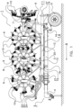
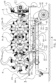
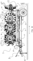
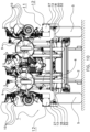
- Figures 1 - 4 show side views and back end views of an embodiment of a haymaking machine according to the invention which is denoted overall by reference numeral 1.
- the haymaking machine 1 is configured to ted a crop and has an elongate frame 2. At a front end 3 of the frame 2, a device 4 is provided for coupling the haymaking machine 1 to a pulling vehicle, such as a tractor (not shown). At the rear end of the agricultural machine 1, wheels 5 are provided for supporting the haymaking machine 1. When the haymaking machine 1 is coupled to a tractor or the like, it can be pulled in a normal direction of travel during operation, which normal direction of travel is indicated in Figure 1 by arrow A.
- the agricultural machine 1 comprises a bearing arm construction pivotable about a number of pivot axes to move the bearing arm construction between the operating position and the transport position.
- the bearing arm construction comprises a pivotable bearing arm support frame 6, a central bearing arm part 7 and two bearing arms 8.
- the pivotable bearing arm support frame 6 is pivotable mounted on the frame 2 and pivotable supports a central bearing arm part 7 which in its turn pivotably is connected to the two bearing arms 8.
- the central bearing arm part 7 and the two bearing arms 8 support a number of crop-processing members 9.
- the two bearing arms 8 with processing members 9 are arranged substantially symmetrically with respect to the frame 2.
- the processing members 9 are arranged rotatably about shafts which are attached to one of the central bearing arm part 7 and the two bearing arms 8.
- the crop-processing members 9 comprise a number of processing elements 10, such as teeth, tines or the like, which are arranged around the circumference of the processing members 9.
- the bearing arm construction is movable to move the processing members 9 between an operating position and a transport position.
- the processing members 9 In the operating position (not shown) the processing members 9 are positioned near the ground in a substantially straight line perpendicular to the normal direction of travel, in such a manner that the processing elements 10 can process crop situated on the ground.
- the bearing arms 9 In the transport position, the bearing arms 9 are folded towards each other and supported by the frame 2, as is illustrated in Figures 1-4 .
- the entire haymaking machine 1 In the transport position, it is desirable that the entire haymaking machine 1 remains substantially within the maximum dimensions which are often imposed by the relevant authorities and government bodies with regard to such machines during transportation. In certain countries, for example, the agricultural machine is only allowed to have a maximum height of four meters and a maximum width of three meters in the transport position. It is desirable that the relatively large crop-processing members 9 are optimally situated so that they remain within the prescribed dimensions in the operating position.
- the processing members 9 are folded up in order to take up a position which is convenient for transportation.
- This transport position may result in the processing elements 10 protruding sideways from the haymaking machine 1 and thus causing a potential risk of injury to people or animals or of damage to objects.
- the agricultural machine 1 comprises a movable shielding construction 11.
- the shielding construction 11 comprises at each of opposite sides of the agricultural machine 1 a shielding beam 12 movable between a lower position, shown in Figures 1 , 3 and 5 , and a shielding position, shown in Figures 2 , 4 and 6 .
- the shielding beams 12 are arranged at a height in the range from 1 meters up to 2 meters, preferably at a height in the range from 1.2 meters to 1.7 meters. In this height range, the shielding beams 12 may prevent that a person is directly hit by one the processing elements 10.
- this desired height of the shielding beams 12 may prevent or hinder movement of the processing members between the operating position and the transport position. By moving the shielding beams 12 to the lower position, the shielding beams 12 may no longer hinder or prevent movement of the processing members between the operating position and the transport position.
- the drive mechanism 14 comprises a first drive axle 15 and two second drive axles 16.
- a front link arm 17 is integrally formed, perpendicularly to the longitudinal direction of the first drive axle 15.
- the outer ends of the second drive axles 16 are each integrally formed with a back link arm 18 perpendicularly to the longitudinal direction of the second drive axle 16.
- the free ends of the front link arms 17 and the back link arms 18 are pivotably connected to one of the shielding beams 12.
- Each rotation transfer arm 19 of the second drive axle 16 is connected with a connection rod 20 to a rotation transfer arm 19 of the first drive axle 15.
- the actuator 13 is mechanically connected to the first drive axle 15 by a rotation arm 21. Extension and retraction of the actuator 13 results in rotation of the first drive axle 15 and, as a result, in a tilting movement of the front link arms 17. Furthermore, rotation of the first drive axle 15 results in a rotation of the second drive axles 16 via the rotation transfer arms 19 and the connection rods 20. The rotation of each of the second drive axles 16 in its turns results in a tilting movement of the back link arms 18.
- the frame 2, the front link arm 17, the back link arm 18 and the shielding beam 12, at each side of the agricultural machine 1 form a four-bar link mechanism.
- simultaneous tilting movements of the front link arm 17 and the back link arm 18, at one side of the agricultural machine 1 will result in that the shielding beam 12 at that side will move between the shielding position and the lower position, wherein the shielding beam 12 remains orientated substantially horizontally.
- the shielding beams 12 In the movements of the shielding beams 12 between the lower position and the shielding position, the shielding beams remain in a substantially vertical plane. This has the advantage that the shielding beams remain both in the lower position and the shielding position relatively close to the frame.
- the front link arms 17 and back link arms 18 are directed substantially horizontally and in the normal direction of movement A.
- the front link arms 17 and back link arms 18 are directed substantially vertically and upwards.
- This backwards movement has the advantage that the shielding beams 12 are moved further backwards to provide more shielding of the processing members 9 towards the back of the agricultural machine 1.
- the shielding beams 12 In the shielding position of the shielding beams 12 in the shown embodiment, the shielding beams 12 extend at the backside of the agricultural machine 1 beyond the processing members 9 carried, in the transport position, by the central bearing arm part 7. As a result, the shielding beams 12 provide shielding of the processing members 9 up to and passed the back end corners of the agricultural machine 1.
- an elongate rod shaped shielding element 22 is provided at the front side of the agricultural machine.
- the shielding element 22 is connected with both front ends of the shielding beams 12 to provide a shielding of the processing members 9 at the front end and front parts of the sides of the agricultural machine 1.
- a shielding element support frame 23 is mounted on a front side of the frame 2 to provide a stationary mounting location 24 for pivotable support of the shielding element 22 at the front side in a fixed position with respect to the frame 2.
- the ends 25 of the shielding element 22 are slidably and rotatably mounted in a sliding groove 26 mounted on the shielding beams 12, so that the ends 25 will follow, but not hinder, movement of the shielding beams 12 between the lower position and the shielding position.
- the advantage of the stationary mounting location 24 of the shielding element 22 is that the front end of the shielding element 22 does not move forwards when the shielding beams 12 are brought from the shielding position to the lower position.
- the shielding element 12 would be allowed to move forward, it may interfere with the movement of a pulling vehicle pulling the agricultural machine 1, in particular when the combination of pulling vehicle and the agricultural machine 1 are not aligned with respect to each other, for example when the combination makes a turn.
- the height of the mounting location 24 is selected such that in the shielding position of the shielding beams 12, the shielding element 22 runs substantially horizontally and substantially at the same height as the shielding beams 12.
- the combination of the shielding beams 12 and the shielding element 22 provide a continuous shielding of the processing members 9 at the front end, at opposite sides, and at the corner areas of a back end of the agricultural machine 1, as shown in Figure 6 .
- the front and back ends of the shielding beams are provided with a plate shaped marking object 27 to mark a corner and/or side of the agricultural machine 1.
- the presence of the shielding beams 12 may prevent or hinder movement of the processing members between the operating position and the transport position.
- the unfolding of the bearing arms 8 with respect to the central bearing arm part 7 may not be carried out when the shielding beams 12 are positioned in the shielding position.
- the agricultural machine 1 comprises a safety device configured to avoid that the actuator or actuators that actuate the folding and unfolding of the bearing arms 8 can be actuated when the shielding beams 12 are in the shielding position.
- the safety device comprises a shut-off valve 28 arranged in a hydraulic drive circuit of the folding and unfolding actuator or actuators. The shut-off valve 28 is movable between a closed position and an open position.
- the shut-off valve 28 is mechanically linked to the rotation arm 21 of the actuator 13 so that the shut-off valve 28 is arranged in the closed position when the shielding beams 12 are in the shielding position, and the shut-off valve 28 is arranged in the open position when the shielding beams are in the lower position.
- Figures 6 - 10 show side views and back end views of an alternative embodiment of a haymaking machine according to the invention.
- the same parts or parts having the same or substantially the same function are indicated by corresponding reference numerals as used in Figures 1-6 .
- the haymaking machine 1 of Figures 6 - 10 is configured to ted a crop. When the haymaking machine 1 is coupled to a tractor or the like, it can be pulled in a normal direction of travel A.
- the haymaking machine 1 comprises a bearing arm construction having a pivotable bearing arm support frame 6, a central bearing arm part 7 and two bearing arms 8.
- the bearing arm construction is, similarly to the embodiment of Figures 1-6 , movable to move the processing members 9 between an operating position and a transport position. Main difference is that in the bearing arm construction of Figures 6-10 , the bearing arms carry more processing members 9 and are pivotable.
- the processing members 9 are folded up in order to take up a position which is convenient for transportation.
- This transport position results in the processing elements 10 protruding sideways from the haymaking machine 1 and thus causing a potential risk of injury to people or animals or of damage to objects.
- the agricultural machine 1 comprises a movable shielding construction 11 to shield the processing members 9 during transport.
- the shielding construction 11 comprises at each of opposite sides of the agricultural machine 1 a shielding beam 12 movable between a lower position, shown in Figures 7 , 9 and 11 , and a shielding position, shown in Figures 8 , 10 and 12 .
- the shielding beams 12 are arranged at a height in the range from 1 meters up to 2 meters, preferably at a height in the range from 1.2 meters to 1.7 meters. In this height range, the shielding beams 12 may prevent that a person is directly hit by one the processing elements 10. This desired height of the shielding beams 12 may prevent or hinder movement of the processing members between the operating position and the transport position. By moving the shielding beams 12 to the lower position, the shielding beams 12 may no longer hinder or prevent movement of the processing members between the operating position and the transport position.
- each shielding beam 12 is mounted on a front link arm 17 and a back link arm 18.
- the frame 2, front link arm 17, back link arm 18 and the shielding beam 12, at each side of the agricultural machine 1 form a four-bar link mechanism.
- simultaneous tilting movements of the front link arm 17 and the back link arm 18, at one side of the agricultural machine 1 will result in that the shielding beam 12 at that side will move between the shielding position and the lower position, wherein the shielding beam 12 remains orientated substantially horizontally.
- the frame 2 comprises frame beams 32 at the end of which pivot axes 30 are provided to pivotably support the front and back link arms 17, 18.
- Each of the front link arms 17 and back link arms 18 is pivotably movable with respect to the frame 2 about such pivot axis 30 to make movement between the shielding position and lower position possible.
- the pivot axes 30 extend in a substantially vertical plane and are arranged at an acute angle ⁇ with respect to the horizontal plane normal direction of travel A. As a result of the acute angle ⁇ , the shielding beams 12 will move upwards, backwards with respect with the normal direction of travel A and towards each other, when the shielding beam 12 is moved from the lower position to the shielding position.
- the shielding beams 12 will move downwards, forwards with respect with the normal direction of travel A and away from each other, when the shielding beams 12 is moved from the shielding position to the lower position.
- the acute angle ⁇ is in the shown embodiment about 45 degrees, but may vary in other embodiments in dependence on the desired ratio between displacements in the different directions upwards, backwards and sidewards in the movement of the shielding beam 12 from the lower position to the shielding position and vice versa.
- the angle may for example be in the range 20 to 70 degrees, preferably 35 to 55 degrees.
- the shielding beams 12 are pivotably mounted on the front link arm 17 and the back link arm 18 at second pivot axes 31 to maintain the same orientation of the shielding beams 12 in the lower position and the shielding position.
- the angle of the pivot axes 30 and the second pivot axes substantially correspond.
- an hydraulic actuator 13 is provided to move the shielding beam 12 between the lower position and the shielding position.
- other actuators or actuator arrangements may be provided to move the shielding beams 12 between the lower position and the shielding position.
- the shielding beams 12 when moved from the lower position to the shielding position, will also move backwards, i.e. opposite to the normal direction of travel A.
- This backwards movement has the advantage that the shielding beams 12 are moved further backwards to provide more shielding of the processing members 9 towards the back of the agricultural machine 1.
- the shielding beams 12 In the shielding position of the shielding beams 12 in the shown embodiment, the shielding beams 12 extend at the backside of the agricultural machine 1 beyond the processing members 9 carried, in the transport position, by the central bearing arm part 7. As a result, the shielding beams 12 provide shielding of the processing members 9 up to and passed the back end corners of the agricultural machine 1.
- the presence of the shielding beams 12 may prevent or hinder movement of the processing members between the operating position and the transport position.
- the unfolding of the bearing arms 8 with respect to the central bearing arm part 7 may not be carried out when the shielding beams 12 are positioned in the shielding position.
- a safety device (not shown) may be provided to prevent movement of the bearing arm construction to or from the transport position, when the shielding beams 12 are in the transport position.
- Such movable shielding construction may also be used in any other agricultural machine to shield its processing members, such as for example a soil cultivation machine, a planting machine or harvesting machine having processing members to be shielded in a transportation position.
- the processing members may be movably, in particular rotatably, connected to the bearing arm construction, or may be fixedly connected to the bearing arm construction.
Landscapes
- Life Sciences & Earth Sciences (AREA)
- Environmental Sciences (AREA)
- Soil Working Implements (AREA)
- Agricultural Machines (AREA)
Claims (6)
- Landwirtschaftliche Maschine (1) mit:- einem Rahmen (2), der konfiguriert ist, um an einem Fahrzeug befestigt zu werden, um die landwirtschaftliche Maschine (1) in einer normalen Fahrtrichtung (A) zu bewegen,- einer Lagerarmkonstruktion (6, 7, 8) mit mindestens einem Lagerarm (8), wobei die Lagerarmkonstruktion verschwenkbar an den Rahmen (2) angeschlossen ist, um um eine oder mehrere Schwenkachsen verschwenkbar zu sein, und- mehreren Verarbeitungsgliedern (9) mit Verarbeitungselementen (10) für ein Bearbeiten des Bodens oder ein Verarbeiten eines Ernteguts, wobei die Verarbeitungsglieder (9) durch Verschwenken der mindestens einen Lagerarmkonstruktion um die eine oder die mehreren Schwenkachsen zumindest zwischen einer Betriebsposition und einer Transportposition verlagerbar sind,wobei die landwirtschaftliche Maschine (1) eine bewegliche Abschirmkonstruktion (11) aufweist, um die Bearbeitungsglieder (9) in der Transportposition zumindest teilweise abzuschirmen, wobei die bewegliche Abschirmkonstruktion zwei Abschirmbalken (12) aufweist, die an einander gegenüberliegenden Seite der landwirtschaftlichen Maschine angeordnet sind, wobei die Abschirmbalken zwischen einer Abschirmposition für das mindestens teilweise Abschirmen der Verarbeitungsglieder (9) und einer niedrigeren Position, in der eine Bewegung der Verarbeitungsglieder zwischen der Betriebsposition und der Transportposition möglich ist, beweglich sind,wobei die bewegliche Abschirmkonstruktion (11) konfiguriert ist, um die Abschirmbalken (12) bezüglich der normalen Fahrtrichtung (A) aufwärts und rückwärts zu bewegen, wenn die Abschirmbalken aus der niedrigeren Position in die Abschirmposition bewegt werden, wobei die landwirtschaftliche Maschine eine Sicherungseinrichtung aufweist, die konfiguriert ist, um zu verhindern, dass die Verarbeitungsglieder (9) zwischen der Betriebsposition und der Transportposition bewegt werden können, wenn die bewegliche Abschirmkonstruktion (11) in der Abschirmposition angeordnet ist, und dadurch gekennzeichnet, dass die Sicherheitseinrichtung ein Abschaltventil (28) aufweist, das in einer hydraulischen Antriebsleitung der Lagerarmkonstruktion angeordnet ist, wobei das Abschaltventil zwischen einer geschlossenen Position und einer offenen Position beweglich ist, und wobei das Abschaltventil mechanisch mit der beweglichen Abschirmkonstruktion (11) gekoppelt ist, so dass das Abschaltventil in der geschlossenen Position ist, wenn die Abschirmbalken in der Abschirmposition sind, und das Abschaltventil in der offenen Position angeordnet ist, wenn die Abschirmbalken in der niedrigeren Position sind.
- Landwirtschaftliche Maschine (1) nach Anspruch 1, wobei die bewegliche Abschirmkonstruktion (11) ein langgestrecktes Abschirmelement (22) aufweist, das die beiden einander gegenüberliegenden Abschirmbalken (12) verbindet, um die Vorderseite der Verarbeitungsglieder (9) in der Transportposition abzuschirmen.
- Landwirtschaftliche Maschine (1) nach Anspruch 2, wobei eine Vorderseite des langgestreckten Abschirmelements (11) in einem bezüglich des Rahmens (2) festen Lagerort (24) verschwenkbar gelagert ist, und wobei beide Enden (25) des langgestreckten Abschirmelements gleitend mit dem Abschirmbalken verbunden sind.
- Landwirtschaftliche Maschine (1) nach einem der vorhergehenden Ansprüche, wobei vordere und hintere Enden der Abschirmbalken (12) mit einem plattenförmigen Markierungsobjekt versehen sind, das konfiguriert ist, um eine Ecke und/oder Seite der landwirtschaftlichen Maschine (1) zu markieren.
- Landwirtschaftliche Maschine (1) nach einem der vorhergehenden Ansprüche, wobei die Abschirmbalken (12) und das Abschirmelement (22) konfiguriert sind, um eine durchlaufende Abschirmung der Verarbeitungsglieder (9) an einem vorderen Ende und an gegenüberliegenden Seiten und mindestens in Eckbereichen eines hinteren Endes der landwirtschaftlichen Maschine bereitzustellen.
- Landwirtschaftliche Maschine (1) nach einem der vorhergehenden Ansprüche, wobei die Abschirmbalken (12), wenn sie in der Abschirmposition positioniert sind, in einer Höhe in dem Bereich von 1 m bis 2 m, vorzugsweise in einer Höhe in dem Bereich von 1,2 m bis 1,7 m angeordnet sind.
Priority Applications (1)
| Application Number | Priority Date | Filing Date | Title |
|---|---|---|---|
| SI201432071T SI3552476T1 (sl) | 2013-07-11 | 2014-05-22 | Kmetijski stroj, še posebej stroj za seno |
Applications Claiming Priority (3)
| Application Number | Priority Date | Filing Date | Title |
|---|---|---|---|
| NL2011137A NL2011137C2 (en) | 2013-07-11 | 2013-07-11 | Agricultural machine, in particular a haymaking machine. |
| EP14169421.6A EP2826358B1 (de) | 2013-07-11 | 2014-05-22 | Landwirtschaftliche Maschine, insbesondere eine Heuerntemaschine |
| EP16166128.5A EP3106017B1 (de) | 2013-07-11 | 2014-05-22 | Landwirtschaftliche maschine, insbesondere eine heuerntemaschine |
Related Parent Applications (4)
| Application Number | Title | Priority Date | Filing Date |
|---|---|---|---|
| EP14169421.6A Division EP2826358B1 (de) | 2013-07-11 | 2014-05-22 | Landwirtschaftliche Maschine, insbesondere eine Heuerntemaschine |
| EP14169421.6A Previously-Filed-Application EP2826358B1 (de) | 2013-07-11 | 2014-05-22 | Landwirtschaftliche Maschine, insbesondere eine Heuerntemaschine |
| EP16166128.5A Division-Into EP3106017B1 (de) | 2013-07-11 | 2014-05-22 | Landwirtschaftliche maschine, insbesondere eine heuerntemaschine |
| EP16166128.5A Division EP3106017B1 (de) | 2013-07-11 | 2014-05-22 | Landwirtschaftliche maschine, insbesondere eine heuerntemaschine |
Publications (2)
| Publication Number | Publication Date |
|---|---|
| EP3552476A1 EP3552476A1 (de) | 2019-10-16 |
| EP3552476B1 true EP3552476B1 (de) | 2024-04-10 |
Family
ID=49517585
Family Applications (3)
| Application Number | Title | Priority Date | Filing Date |
|---|---|---|---|
| EP16166128.5A Active EP3106017B1 (de) | 2013-07-11 | 2014-05-22 | Landwirtschaftliche maschine, insbesondere eine heuerntemaschine |
| EP14169421.6A Active EP2826358B1 (de) | 2013-07-11 | 2014-05-22 | Landwirtschaftliche Maschine, insbesondere eine Heuerntemaschine |
| EP19168940.5A Active EP3552476B1 (de) | 2013-07-11 | 2014-05-22 | Landwirtschaftliche maschine, insbesondere eine heuerntemaschine |
Family Applications Before (2)
| Application Number | Title | Priority Date | Filing Date |
|---|---|---|---|
| EP16166128.5A Active EP3106017B1 (de) | 2013-07-11 | 2014-05-22 | Landwirtschaftliche maschine, insbesondere eine heuerntemaschine |
| EP14169421.6A Active EP2826358B1 (de) | 2013-07-11 | 2014-05-22 | Landwirtschaftliche Maschine, insbesondere eine Heuerntemaschine |
Country Status (3)
| Country | Link |
|---|---|
| EP (3) | EP3106017B1 (de) |
| NL (1) | NL2011137C2 (de) |
| SI (3) | SI3552476T1 (de) |
Families Citing this family (1)
| Publication number | Priority date | Publication date | Assignee | Title |
|---|---|---|---|---|
| PL248874B1 (pl) * | 2023-03-24 | 2026-02-09 | Samasz Spolka Z Ograniczona Odpowiedzialnoscia | Przetrząsacz pokosów |
Family Cites Families (5)
| Publication number | Priority date | Publication date | Assignee | Title |
|---|---|---|---|---|
| DE3709097A1 (de) * | 1987-03-20 | 1988-09-29 | Khd Agrartechnik | Kreiselheuwerbungsmaschine |
| DE8712165U1 (de) * | 1987-09-08 | 1987-10-29 | Fella-Werke Gmbh, 8501 Feucht | Schutzvorrichtung für Heuwerbungsmaschinen |
| ATE92240T1 (de) * | 1987-11-19 | 1993-08-15 | Claas Saulgau Gmbh | Schutzvorrichtung fuer kreiselheumaschinen. |
| NL1036115C (nl) * | 2008-10-27 | 2010-04-28 | Lely Patent Nv | Landbouwmachine. |
| DE202011107679U1 (de) * | 2011-11-09 | 2013-02-13 | Alois Pöttinger Maschinenfabrik Gmbh | Heuwerbungsmaschine |
-
2013
- 2013-07-11 NL NL2011137A patent/NL2011137C2/en not_active IP Right Cessation
-
2014
- 2014-05-22 EP EP16166128.5A patent/EP3106017B1/de active Active
- 2014-05-22 EP EP14169421.6A patent/EP2826358B1/de active Active
- 2014-05-22 SI SI201432071T patent/SI3552476T1/sl unknown
- 2014-05-22 SI SI201431661T patent/SI3106017T1/sl unknown
- 2014-05-22 EP EP19168940.5A patent/EP3552476B1/de active Active
- 2014-05-22 SI SI201430294T patent/SI2826358T1/en unknown
Also Published As
| Publication number | Publication date |
|---|---|
| EP2826358A2 (de) | 2015-01-21 |
| EP3106017B1 (de) | 2020-07-01 |
| EP2826358A3 (de) | 2015-04-29 |
| EP2826358B1 (de) | 2017-04-19 |
| SI2826358T1 (en) | 2018-02-28 |
| EP3106017A1 (de) | 2016-12-21 |
| NL2011137C2 (en) | 2015-01-13 |
| SI3552476T1 (sl) | 2024-09-30 |
| EP3552476A1 (de) | 2019-10-16 |
| SI3106017T1 (sl) | 2020-10-30 |
Similar Documents
| Publication | Publication Date | Title |
|---|---|---|
| US6907719B2 (en) | Agricultural implement comprising a transporting device | |
| RU2569294C2 (ru) | Сеноуборочное устройство | |
| US9622404B2 (en) | Integral lateral transport of a mower | |
| JP3549213B2 (ja) | 刈り取った干草を列に並べる干草刈り機 | |
| AU2004285320B2 (en) | Agricultural machine for swathing products lying on the ground | |
| US8910724B2 (en) | Telescoping coulter system and method | |
| AU2012216866B2 (en) | Haymaking machine | |
| EP3370499B1 (de) | Tragarmanordnung | |
| AU2014351686B2 (en) | Agricultural machine, in particular machine for harvesting plant matter, comprising two driven working units that are articulated on a single lateral arm | |
| AU2016335152B2 (en) | Carrier assembly | |
| US20150282426A1 (en) | Forage harvesting machine with an improved deflector | |
| EP3811766B1 (de) | Verbessertes landwirtschaftliches arbeitsgerät | |
| CA2890534C (en) | Device for harvesting long agricultural products and agricultural self-propelled unit for harvesting agricultural products comprising the device | |
| EP3106017B1 (de) | Landwirtschaftliche maschine, insbesondere eine heuerntemaschine | |
| EP1937054B1 (de) | Verstellbarer heurechen | |
| EP2057890B1 (de) | Heuerntemaschine | |
| AU2006208796B2 (en) | Lawn mower provided with an improved folding and unfolding device | |
| EP2445330B1 (de) | Landmaschine | |
| DK2526758T3 (en) | Mower | |
| EP3332628B1 (de) | Landwirtschaftliche arbeitsmaschine | |
| EP2908615B2 (de) | Zetter für auf dem boden liegende pflanzen |
Legal Events
| Date | Code | Title | Description |
|---|---|---|---|
| PUAI | Public reference made under article 153(3) epc to a published international application that has entered the european phase |
Free format text: ORIGINAL CODE: 0009012 |
|
| STAA | Information on the status of an ep patent application or granted ep patent |
Free format text: STATUS: THE APPLICATION HAS BEEN PUBLISHED |
|
| AC | Divisional application: reference to earlier application |
Ref document number: 3106017 Country of ref document: EP Kind code of ref document: P Ref document number: 2826358 Country of ref document: EP Kind code of ref document: P |
|
| AK | Designated contracting states |
Kind code of ref document: A1 Designated state(s): AL AT BE BG CH CY CZ DE DK EE ES FI FR GB GR HR HU IE IS IT LI LT LU LV MC MK MT NL NO PL PT RO RS SE SI SK SM TR |
|
| STAA | Information on the status of an ep patent application or granted ep patent |
Free format text: STATUS: REQUEST FOR EXAMINATION WAS MADE |
|
| 17P | Request for examination filed |
Effective date: 20200416 |
|
| RBV | Designated contracting states (corrected) |
Designated state(s): AL AT BE BG CH CY CZ DE DK EE ES FI FR GB GR HR HU IE IS IT LI LT LU LV MC MK MT NL NO PL PT RO RS SE SI SK SM TR |
|
| STAA | Information on the status of an ep patent application or granted ep patent |
Free format text: STATUS: EXAMINATION IS IN PROGRESS |
|
| 17Q | First examination report despatched |
Effective date: 20200807 |
|
| RAP3 | Party data changed (applicant data changed or rights of an application transferred) |
Owner name: FORAGE COMPANY B.V. |
|
| GRAP | Despatch of communication of intention to grant a patent |
Free format text: ORIGINAL CODE: EPIDOSNIGR1 |
|
| STAA | Information on the status of an ep patent application or granted ep patent |
Free format text: STATUS: GRANT OF PATENT IS INTENDED |
|
| INTG | Intention to grant announced |
Effective date: 20240122 |
|
| GRAS | Grant fee paid |
Free format text: ORIGINAL CODE: EPIDOSNIGR3 |
|
| GRAA | (expected) grant |
Free format text: ORIGINAL CODE: 0009210 |
|
| STAA | Information on the status of an ep patent application or granted ep patent |
Free format text: STATUS: THE PATENT HAS BEEN GRANTED |
|
| AC | Divisional application: reference to earlier application |
Ref document number: 2826358 Country of ref document: EP Kind code of ref document: P Ref document number: 3106017 Country of ref document: EP Kind code of ref document: P |
|
| AK | Designated contracting states |
Kind code of ref document: B1 Designated state(s): AL AT BE BG CH CY CZ DE DK EE ES FI FR GB GR HR HU IE IS IT LI LT LU LV MC MK MT NL NO PL PT RO RS SE SI SK SM TR |
|
| REG | Reference to a national code |
Ref country code: GB Ref legal event code: FG4D |
|
| REG | Reference to a national code |
Ref country code: CH Ref legal event code: EP |
|
| REG | Reference to a national code |
Ref country code: DE Ref legal event code: R096 Ref document number: 602014089938 Country of ref document: DE |
|
| REG | Reference to a national code |
Ref country code: IE Ref legal event code: FG4D |
|
| PGFP | Annual fee paid to national office [announced via postgrant information from national office to epo] |
Ref country code: IE Payment date: 20240524 Year of fee payment: 11 |
|
| REG | Reference to a national code |
Ref country code: LT Ref legal event code: MG9D |
|
| REG | Reference to a national code |
Ref country code: NL Ref legal event code: MP Effective date: 20240410 |
|
| REG | Reference to a national code |
Ref country code: AT Ref legal event code: MK05 Ref document number: 1673860 Country of ref document: AT Kind code of ref document: T Effective date: 20240410 |
|
| PG25 | Lapsed in a contracting state [announced via postgrant information from national office to epo] |
Ref country code: NL Free format text: LAPSE BECAUSE OF FAILURE TO SUBMIT A TRANSLATION OF THE DESCRIPTION OR TO PAY THE FEE WITHIN THE PRESCRIBED TIME-LIMIT Effective date: 20240410 |
|
| PG25 | Lapsed in a contracting state [announced via postgrant information from national office to epo] |
Ref country code: NL Free format text: LAPSE BECAUSE OF FAILURE TO SUBMIT A TRANSLATION OF THE DESCRIPTION OR TO PAY THE FEE WITHIN THE PRESCRIBED TIME-LIMIT Effective date: 20240410 |
|
| PG25 | Lapsed in a contracting state [announced via postgrant information from national office to epo] |
Ref country code: IS Free format text: LAPSE BECAUSE OF FAILURE TO SUBMIT A TRANSLATION OF THE DESCRIPTION OR TO PAY THE FEE WITHIN THE PRESCRIBED TIME-LIMIT Effective date: 20240810 |
|
| PG25 | Lapsed in a contracting state [announced via postgrant information from national office to epo] |
Ref country code: BG Free format text: LAPSE BECAUSE OF FAILURE TO SUBMIT A TRANSLATION OF THE DESCRIPTION OR TO PAY THE FEE WITHIN THE PRESCRIBED TIME-LIMIT Effective date: 20240410 |
|
| PG25 | Lapsed in a contracting state [announced via postgrant information from national office to epo] |
Ref country code: FI Free format text: LAPSE BECAUSE OF FAILURE TO SUBMIT A TRANSLATION OF THE DESCRIPTION OR TO PAY THE FEE WITHIN THE PRESCRIBED TIME-LIMIT Effective date: 20240410 Ref country code: HR Free format text: LAPSE BECAUSE OF FAILURE TO SUBMIT A TRANSLATION OF THE DESCRIPTION OR TO PAY THE FEE WITHIN THE PRESCRIBED TIME-LIMIT Effective date: 20240410 |
|
| PG25 | Lapsed in a contracting state [announced via postgrant information from national office to epo] |
Ref country code: GR Free format text: LAPSE BECAUSE OF FAILURE TO SUBMIT A TRANSLATION OF THE DESCRIPTION OR TO PAY THE FEE WITHIN THE PRESCRIBED TIME-LIMIT Effective date: 20240711 |
|
| PG25 | Lapsed in a contracting state [announced via postgrant information from national office to epo] |
Ref country code: PT Free format text: LAPSE BECAUSE OF FAILURE TO SUBMIT A TRANSLATION OF THE DESCRIPTION OR TO PAY THE FEE WITHIN THE PRESCRIBED TIME-LIMIT Effective date: 20240812 |
|
| PG25 | Lapsed in a contracting state [announced via postgrant information from national office to epo] |
Ref country code: ES Free format text: LAPSE BECAUSE OF FAILURE TO SUBMIT A TRANSLATION OF THE DESCRIPTION OR TO PAY THE FEE WITHIN THE PRESCRIBED TIME-LIMIT Effective date: 20240410 |
|
| PG25 | Lapsed in a contracting state [announced via postgrant information from national office to epo] |
Ref country code: AT Free format text: LAPSE BECAUSE OF FAILURE TO SUBMIT A TRANSLATION OF THE DESCRIPTION OR TO PAY THE FEE WITHIN THE PRESCRIBED TIME-LIMIT Effective date: 20240410 |
|
| PG25 | Lapsed in a contracting state [announced via postgrant information from national office to epo] |
Ref country code: PL Free format text: LAPSE BECAUSE OF FAILURE TO SUBMIT A TRANSLATION OF THE DESCRIPTION OR TO PAY THE FEE WITHIN THE PRESCRIBED TIME-LIMIT Effective date: 20240410 |
|
| PGFP | Annual fee paid to national office [announced via postgrant information from national office to epo] |
Ref country code: SI Payment date: 20240510 Year of fee payment: 11 |
|
| PG25 | Lapsed in a contracting state [announced via postgrant information from national office to epo] |
Ref country code: LV Free format text: LAPSE BECAUSE OF FAILURE TO SUBMIT A TRANSLATION OF THE DESCRIPTION OR TO PAY THE FEE WITHIN THE PRESCRIBED TIME-LIMIT Effective date: 20240410 |
|
| PG25 | Lapsed in a contracting state [announced via postgrant information from national office to epo] |
Ref country code: PT Free format text: LAPSE BECAUSE OF FAILURE TO SUBMIT A TRANSLATION OF THE DESCRIPTION OR TO PAY THE FEE WITHIN THE PRESCRIBED TIME-LIMIT Effective date: 20240812 Ref country code: PL Free format text: LAPSE BECAUSE OF FAILURE TO SUBMIT A TRANSLATION OF THE DESCRIPTION OR TO PAY THE FEE WITHIN THE PRESCRIBED TIME-LIMIT Effective date: 20240410 Ref country code: NO Free format text: LAPSE BECAUSE OF FAILURE TO SUBMIT A TRANSLATION OF THE DESCRIPTION OR TO PAY THE FEE WITHIN THE PRESCRIBED TIME-LIMIT Effective date: 20240710 Ref country code: LV Free format text: LAPSE BECAUSE OF FAILURE TO SUBMIT A TRANSLATION OF THE DESCRIPTION OR TO PAY THE FEE WITHIN THE PRESCRIBED TIME-LIMIT Effective date: 20240410 Ref country code: IS Free format text: LAPSE BECAUSE OF FAILURE TO SUBMIT A TRANSLATION OF THE DESCRIPTION OR TO PAY THE FEE WITHIN THE PRESCRIBED TIME-LIMIT Effective date: 20240810 Ref country code: HR Free format text: LAPSE BECAUSE OF FAILURE TO SUBMIT A TRANSLATION OF THE DESCRIPTION OR TO PAY THE FEE WITHIN THE PRESCRIBED TIME-LIMIT Effective date: 20240410 Ref country code: GR Free format text: LAPSE BECAUSE OF FAILURE TO SUBMIT A TRANSLATION OF THE DESCRIPTION OR TO PAY THE FEE WITHIN THE PRESCRIBED TIME-LIMIT Effective date: 20240711 Ref country code: FI Free format text: LAPSE BECAUSE OF FAILURE TO SUBMIT A TRANSLATION OF THE DESCRIPTION OR TO PAY THE FEE WITHIN THE PRESCRIBED TIME-LIMIT Effective date: 20240410 Ref country code: ES Free format text: LAPSE BECAUSE OF FAILURE TO SUBMIT A TRANSLATION OF THE DESCRIPTION OR TO PAY THE FEE WITHIN THE PRESCRIBED TIME-LIMIT Effective date: 20240410 Ref country code: BG Free format text: LAPSE BECAUSE OF FAILURE TO SUBMIT A TRANSLATION OF THE DESCRIPTION OR TO PAY THE FEE WITHIN THE PRESCRIBED TIME-LIMIT Effective date: 20240410 Ref country code: AT Free format text: LAPSE BECAUSE OF FAILURE TO SUBMIT A TRANSLATION OF THE DESCRIPTION OR TO PAY THE FEE WITHIN THE PRESCRIBED TIME-LIMIT Effective date: 20240410 Ref country code: RS Free format text: LAPSE BECAUSE OF FAILURE TO SUBMIT A TRANSLATION OF THE DESCRIPTION OR TO PAY THE FEE WITHIN THE PRESCRIBED TIME-LIMIT Effective date: 20240710 |
|
| REG | Reference to a national code |
Ref country code: CH Ref legal event code: PL |
|
| REG | Reference to a national code |
Ref country code: DE Ref legal event code: R097 Ref document number: 602014089938 Country of ref document: DE |
|
| PG25 | Lapsed in a contracting state [announced via postgrant information from national office to epo] |
Ref country code: DK Free format text: LAPSE BECAUSE OF FAILURE TO SUBMIT A TRANSLATION OF THE DESCRIPTION OR TO PAY THE FEE WITHIN THE PRESCRIBED TIME-LIMIT Effective date: 20240410 |
|
| PG25 | Lapsed in a contracting state [announced via postgrant information from national office to epo] |
Ref country code: LU Free format text: LAPSE BECAUSE OF NON-PAYMENT OF DUE FEES Effective date: 20240522 |
|
| PG25 | Lapsed in a contracting state [announced via postgrant information from national office to epo] |
Ref country code: EE Free format text: LAPSE BECAUSE OF FAILURE TO SUBMIT A TRANSLATION OF THE DESCRIPTION OR TO PAY THE FEE WITHIN THE PRESCRIBED TIME-LIMIT Effective date: 20240410 |
|
| PG25 | Lapsed in a contracting state [announced via postgrant information from national office to epo] |
Ref country code: CZ Free format text: LAPSE BECAUSE OF FAILURE TO SUBMIT A TRANSLATION OF THE DESCRIPTION OR TO PAY THE FEE WITHIN THE PRESCRIBED TIME-LIMIT Effective date: 20240410 |
|
| PG25 | Lapsed in a contracting state [announced via postgrant information from national office to epo] |
Ref country code: SK Free format text: LAPSE BECAUSE OF FAILURE TO SUBMIT A TRANSLATION OF THE DESCRIPTION OR TO PAY THE FEE WITHIN THE PRESCRIBED TIME-LIMIT Effective date: 20240410 Ref country code: RO Free format text: LAPSE BECAUSE OF FAILURE TO SUBMIT A TRANSLATION OF THE DESCRIPTION OR TO PAY THE FEE WITHIN THE PRESCRIBED TIME-LIMIT Effective date: 20240410 |
|
| PG25 | Lapsed in a contracting state [announced via postgrant information from national office to epo] |
Ref country code: SM Free format text: LAPSE BECAUSE OF FAILURE TO SUBMIT A TRANSLATION OF THE DESCRIPTION OR TO PAY THE FEE WITHIN THE PRESCRIBED TIME-LIMIT Effective date: 20240410 |
|
| PG25 | Lapsed in a contracting state [announced via postgrant information from national office to epo] |
Ref country code: SM Free format text: LAPSE BECAUSE OF FAILURE TO SUBMIT A TRANSLATION OF THE DESCRIPTION OR TO PAY THE FEE WITHIN THE PRESCRIBED TIME-LIMIT Effective date: 20240410 Ref country code: SK Free format text: LAPSE BECAUSE OF FAILURE TO SUBMIT A TRANSLATION OF THE DESCRIPTION OR TO PAY THE FEE WITHIN THE PRESCRIBED TIME-LIMIT Effective date: 20240410 Ref country code: RO Free format text: LAPSE BECAUSE OF FAILURE TO SUBMIT A TRANSLATION OF THE DESCRIPTION OR TO PAY THE FEE WITHIN THE PRESCRIBED TIME-LIMIT Effective date: 20240410 Ref country code: LU Free format text: LAPSE BECAUSE OF NON-PAYMENT OF DUE FEES Effective date: 20240522 Ref country code: EE Free format text: LAPSE BECAUSE OF FAILURE TO SUBMIT A TRANSLATION OF THE DESCRIPTION OR TO PAY THE FEE WITHIN THE PRESCRIBED TIME-LIMIT Effective date: 20240410 Ref country code: DK Free format text: LAPSE BECAUSE OF FAILURE TO SUBMIT A TRANSLATION OF THE DESCRIPTION OR TO PAY THE FEE WITHIN THE PRESCRIBED TIME-LIMIT Effective date: 20240410 Ref country code: CZ Free format text: LAPSE BECAUSE OF FAILURE TO SUBMIT A TRANSLATION OF THE DESCRIPTION OR TO PAY THE FEE WITHIN THE PRESCRIBED TIME-LIMIT Effective date: 20240410 Ref country code: MC Free format text: LAPSE BECAUSE OF FAILURE TO SUBMIT A TRANSLATION OF THE DESCRIPTION OR TO PAY THE FEE WITHIN THE PRESCRIBED TIME-LIMIT Effective date: 20240410 Ref country code: CH Free format text: LAPSE BECAUSE OF NON-PAYMENT OF DUE FEES Effective date: 20240531 |
|
| PG25 | Lapsed in a contracting state [announced via postgrant information from national office to epo] |
Ref country code: IT Free format text: LAPSE BECAUSE OF FAILURE TO SUBMIT A TRANSLATION OF THE DESCRIPTION OR TO PAY THE FEE WITHIN THE PRESCRIBED TIME-LIMIT Effective date: 20240410 |
|
| PLBE | No opposition filed within time limit |
Free format text: ORIGINAL CODE: 0009261 |
|
| STAA | Information on the status of an ep patent application or granted ep patent |
Free format text: STATUS: NO OPPOSITION FILED WITHIN TIME LIMIT |
|
| REG | Reference to a national code |
Ref country code: BE Ref legal event code: MM Effective date: 20240531 |
|
| 26N | No opposition filed |
Effective date: 20250113 |
|
| GBPC | Gb: european patent ceased through non-payment of renewal fee |
Effective date: 20240710 |
|
| PG25 | Lapsed in a contracting state [announced via postgrant information from national office to epo] |
Ref country code: BE Free format text: LAPSE BECAUSE OF NON-PAYMENT OF DUE FEES Effective date: 20240531 |
|
| PG25 | Lapsed in a contracting state [announced via postgrant information from national office to epo] |
Ref country code: GB Free format text: LAPSE BECAUSE OF NON-PAYMENT OF DUE FEES Effective date: 20240710 |
|
| PGFP | Annual fee paid to national office [announced via postgrant information from national office to epo] |
Ref country code: DE Payment date: 20250521 Year of fee payment: 12 |
|
| PGFP | Annual fee paid to national office [announced via postgrant information from national office to epo] |
Ref country code: FR Payment date: 20250528 Year of fee payment: 12 |
|
| PG25 | Lapsed in a contracting state [announced via postgrant information from national office to epo] |
Ref country code: CY Free format text: LAPSE BECAUSE OF FAILURE TO SUBMIT A TRANSLATION OF THE DESCRIPTION OR TO PAY THE FEE WITHIN THE PRESCRIBED TIME-LIMIT; INVALID AB INITIO Effective date: 20140522 |
|
| PG25 | Lapsed in a contracting state [announced via postgrant information from national office to epo] |
Ref country code: HU Free format text: LAPSE BECAUSE OF FAILURE TO SUBMIT A TRANSLATION OF THE DESCRIPTION OR TO PAY THE FEE WITHIN THE PRESCRIBED TIME-LIMIT; INVALID AB INITIO Effective date: 20140522 |
|
| PG25 | Lapsed in a contracting state [announced via postgrant information from national office to epo] |
Ref country code: SE Free format text: LAPSE BECAUSE OF FAILURE TO SUBMIT A TRANSLATION OF THE DESCRIPTION OR TO PAY THE FEE WITHIN THE PRESCRIBED TIME-LIMIT Effective date: 20240410 |
|
| PG25 | Lapsed in a contracting state [announced via postgrant information from national office to epo] |
Ref country code: IE Free format text: LAPSE BECAUSE OF NON-PAYMENT OF DUE FEES Effective date: 20250522 |