EP3552292B1 - Energiespeichervorrichtung und deren verwendung - Google Patents
Energiespeichervorrichtung und deren verwendung Download PDFInfo
- Publication number
- EP3552292B1 EP3552292B1 EP18706204.7A EP18706204A EP3552292B1 EP 3552292 B1 EP3552292 B1 EP 3552292B1 EP 18706204 A EP18706204 A EP 18706204A EP 3552292 B1 EP3552292 B1 EP 3552292B1
- Authority
- EP
- European Patent Office
- Prior art keywords
- energy storage
- storage device
- electrochemical energy
- profile
- power
- Prior art date
- Legal status (The legal status is an assumption and is not a legal conclusion. Google has not performed a legal analysis and makes no representation as to the accuracy of the status listed.)
- Active
Links
Images

Classifications
-
- H—ELECTRICITY
- H02—GENERATION; CONVERSION OR DISTRIBUTION OF ELECTRIC POWER
- H02J—ELECTRIC POWER NETWORKS; CIRCUIT ARRANGEMENTS OR SYSTEMS FOR SUPPLYING OR DISTRIBUTING ELECTRIC POWER; SYSTEMS FOR STORING ELECTRIC ENERGY
- H02J15/00—Systems for storing electric energy specially adapted for power networks
-
- G—PHYSICS
- G05—CONTROLLING; REGULATING
- G05B—CONTROL OR REGULATING SYSTEMS IN GENERAL; FUNCTIONAL ELEMENTS OF SUCH SYSTEMS; MONITORING OR TESTING ARRANGEMENTS FOR SUCH SYSTEMS OR ELEMENTS
- G05B13/00—Adaptive control systems, i.e. systems automatically adjusting themselves to have a performance which is optimum according to some preassigned criterion
- G05B13/02—Adaptive control systems, i.e. systems automatically adjusting themselves to have a performance which is optimum according to some preassigned criterion electric
- G05B13/0205—Adaptive control systems, i.e. systems automatically adjusting themselves to have a performance which is optimum according to some preassigned criterion electric not using a model or a simulator of the controlled system
- G05B13/021—Adaptive control systems, i.e. systems automatically adjusting themselves to have a performance which is optimum according to some preassigned criterion electric not using a model or a simulator of the controlled system in which a variable is automatically adjusted to optimise the performance
-
- H—ELECTRICITY
- H02—GENERATION; CONVERSION OR DISTRIBUTION OF ELECTRIC POWER
- H02J—ELECTRIC POWER NETWORKS; CIRCUIT ARRANGEMENTS OR SYSTEMS FOR SUPPLYING OR DISTRIBUTING ELECTRIC POWER; SYSTEMS FOR STORING ELECTRIC ENERGY
- H02J3/00—Circuit arrangements for AC mains or AC distribution networks
- H02J3/003—Load forecast, e.g. methods or systems for forecasting future load demand
-
- H—ELECTRICITY
- H02—GENERATION; CONVERSION OR DISTRIBUTION OF ELECTRIC POWER
- H02J—ELECTRIC POWER NETWORKS; CIRCUIT ARRANGEMENTS OR SYSTEMS FOR SUPPLYING OR DISTRIBUTING ELECTRIC POWER; SYSTEMS FOR STORING ELECTRIC ENERGY
- H02J3/00—Circuit arrangements for AC mains or AC distribution networks
- H02J3/28—Arrangements for balancing of the load in networks by storage of energy
Definitions
- the invention relates in particular to a flexible control unit for the optimized operation of hybrid storage systems.
- Typical classification features for energy storage systems are the energy and power density, the typical discharge time, the temperature range in which the storage systems can be operated, the efficiency, the expected service life under certain operating conditions and, last but not least, the investment costs related to the storage capacity.
- WO 2016/150815 A1 US 2016/334821 A1 and US 2016/218511 A1 are state-of-the-art documents.
- the object of the invention is to optimize and use an electrical energy storage device in a simple, flexible and effective manner with regard to certain criteria, in particular with regard to service life, efficiency, energy density, power density, discharge time, costs.
- the object is achieved by an energy storage device according to main claim 1 and a use according to secondary claim 7.
- hybrid storage It has been recognized that not every energy storage device is equally well suited for every application. There are often applications for which a combination of different memories makes sense in order to combine advantages, eliminate disadvantages or simply to be able to cover special requirements at all. Solutions in which different types of storage are interconnected are referred to as hybrid storage.
- the service life of the individual energy storage devices can be increased.
- the efficiency of the individual energy storage devices can be increased.
- the maintenance costs for the energy storage devices can be reduced. It can be made possible to save on peripherals, such as cooling components, for example.
- the investment costs can also be reduced.
- the criterion according to which optimization is to be carried out can be selected. New knowledge about the individual energy storage devices can be easily implemented by updating the evaluation profiles. Active control of the overall system or the energy storage device is possible. By avoiding critical operating states, the accuracy of the prediction can be increased and the ability to estimate the service life can be improved.
- a respective mapping of the evaluation profile can be switched as a matrix or as a three-dimensional graph.
- the computer device can expand the evaluation profiles in terms of number of scope and / or degree of detail by means of values recorded by the measuring device.
- additional evaluation profiles can be stored in the data storage device.
- the operating state values of the energy storage devices can be temperature, charge state, humidity, pressure, radiation values, capacity and / or power.
- the respective ratios of a current power to the maximum power of a respective energy storage device and the ratio of the current power to the maximum power of the energy storage device can be different.
- control device can be designed as a regulating device by means of an actual / target comparison.
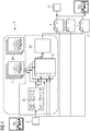
- Figure 1 shows an embodiment of an energy storage device 1 according to the invention.
- the present invention describes a basic concept for flexible control by means of a control device 11 for flexible control, which makes it possible to optimize the operation of hybrid energy storage devices 5 according to certain selectable aspects.
- the basis for the optimization is provided by empirical values collected from the individual energy storage devices 5 as evaluation profiles BP.
- a preferred embodiment of an evaluation profile BP is an evaluation matrix.
- the required load profile P (t) is broken down into partial load profiles Pi (t) and distributed to the individual energy storage devices 5 on the basis of the evaluation matrices, the current operating states of the energy storage devices 5 and an optimization method.
- the optimization process can distribute the load profiles according to various adjustable criteria.
- the partial load profiles Pi (t) are compared with the total load profile P (t). In this way, deviations are determined and they can be counteracted. This can be done by means of a feedback path.
- the functioning of the concept represents Figure 1 represent.
- Input signals of a computer 9 are the power P (t) required by the system and current status reports or operating status values of the individual energy storage devices 5.
- the computer 9 now first calculates partial load profiles Pi (t) of different sizes from the required load profile P (t). For each of these part-load profiles Pi (t), it is then checked how well the individual energy storage devices 5 are suitable for fulfilling the respective part-load profile Pi (t). The analysis is carried out based on the respective current operating state values of the individual energy storage devices 5 recorded by the measuring device 3 and the evaluation matrix stored for the respective energy storage device 5 in a data storage device 7 as an exemplary embodiment for an evaluation profile BP. The optimization assigns the partial load profiles Pi (t) to the individual energy storage devices 5 in such a way that the best possible result is achieved depending on the set criterion.
- evaluation profiles BP or evaluation matrices are stored in the data storage device 7 for the different aspects.
- Figure 1 shows a schematic representation of an energy saving device 1 with incoming load profile P (t), the following evaluation algorithms and subsequent profile assignment for each individual type of energy storage device 5.
- incoming load profile P (t) the following evaluation algorithms and subsequent profile assignment for each individual type of energy storage device 5.
- Measuring device 3, data storage device 7, computer device 9 and control device 11 can be combined as a control unit with flexible optimization.
- An energy storage device 1 according to the invention can be designed for a long service life of a hybrid storage system that is optimized for a long service life and consists of various electrochemical storage systems.
- An energy storage device 1 according to the invention can be designed as an operational management of a hybrid storage device that is optimized for a long service life and consists of electrochemical storage devices and non-electrochemical storage devices.
- the management of a hybrid storage system consisting of electrochemical storage and non-electrochemical storage can be optimized at the expense of, for example, costs per kilowatt-hour of stored energy.
- An operational management of a hybrid storage system consisting of different electrochemical storage systems can be optimized for the efficiency, for example.
- An operational management of a hybrid storage system consisting of electrochemical storage and non-electrochemical storage, can be optimized for the efficiency.
- the mode of operation of a hybrid storage system can be achieved by utilizing the advantageous evaluation schemes and / or by avoiding the disadvantageous evaluation schemes be optimized. With the help of partial load profile evaluations, it is possible to predict favorable times for maintenance cycles.
- the following hardware features can indicate that an energy storage device 1 according to the invention was used to control a hybrid storage device or a system of different energy storage devices 5: Two or more different types of energy storage devices 5 are controlled via a common control unit.
- the load profile of the hybrid storage system is typically composed of several different partial load profiles.
- the control unit contains a module for data storage.
- Figure 2 shows an embodiment of an evaluation profile BP according to the invention.
- associated evaluation matrices with respective parameters are stored in a data storage device 7 for each individual energy storage device 5 and each adjustable optimization criterion.
- the parameters can be the state of charge SOC and the temperature T, for example. These are determined from measurement data by means of a measuring device 3 and can be continuously adapted during operation.
- the evaluation matrices is due optimized management, a more accurate age estimation and thus a more accurate prediction is possible.
- the evaluation matrices contain information on how certain operating points affect certain criteria. There is an associated evaluation matrix for each energy storage device 5 and each criterion.
- evaluation matrices can be expanded as the level of knowledge increases. Further evaluation matrices can also be easily added.
- Figure 2 shows an example of an evaluation matrix.
- a measured calendar aging of a lithium-ion storage device is shown as a function of the state of charge SOC and the temperature T. So shows Figure 2 As an example of a described evaluation matrix, the influence of the state of charge SOC (State of Charge) and the temperature T on the calendar aging of an electrochemical energy store as an embodiment of an energy storage device 5, based on individual lithium-ion cells of a specific cell chemistry.
- the greatest aging occurs when the storage tank is fully charged in the upper temperature range. By avoiding this operating range, the aging of the storage component or the energy storage device 5 can be reduced in a targeted manner.
- FIG. 3 shows an embodiment of an inventive use of an energy storage device.
- a measuring device is used to record S1 an electrical load profile to be provided and operating state values of energy storage devices.
- data storage of at least one impact of operating parameters on a respective criterion of a respective energy storage device is carried out for a respective energy storage device.
- a third step S3 divides the electrical load profile to be provided into partial load profiles.
- a fourth step S4 assigns a respective partial load profile to a respective best energy storage device with regard to the required criterion, taking into account the operating state value or the operating state values of the energy storage device concerned.
- the energy storage devices selected by means of the assignment S4 are activated for jointly providing electrical power for the required electrical load profile.
Landscapes
- Engineering & Computer Science (AREA)
- Power Engineering (AREA)
- Health & Medical Sciences (AREA)
- Artificial Intelligence (AREA)
- Computer Vision & Pattern Recognition (AREA)
- Evolutionary Computation (AREA)
- Medical Informatics (AREA)
- Software Systems (AREA)
- Physics & Mathematics (AREA)
- General Physics & Mathematics (AREA)
- Automation & Control Theory (AREA)
- Secondary Cells (AREA)
- Supply And Distribution Of Alternating Current (AREA)
- Charge And Discharge Circuits For Batteries Or The Like (AREA)
Description
- Die Erfindung betrifft insbesondere eine flexible Steuereinheit für den optimierten Betrieb von Hybridspeichern.
- Der Wunsch elektrische Energie zu speichern und zu einem späteren Zeitpunkt zu nutzen gewinnt nicht zuletzt durch die steigende Indikation von erneuerbaren Energieformen wie Sonne und Wind immer mehr an Bedeutung. Zur Speicherung von Energie gibt es mittlerweile eine große und ständig wachsende Anzahl an Lösungsansätzen. Diese lassen sich grob in mechanische, physikalische oder chemische /elektrochemische Speicher einteilen. Bekannte Beispiele sind Schwungräder, Pumpspeicherkraftwerke und verschiedene Akkumulatoren. Alle diese beschriebenen Speicher besitzen dabei sehr unterschiedliche technische Eigenschaften und technologiespezifische Vor- und Nachteile.
- Typische Klassifizierungsmerkmale für Energiespeicher sind die Energie- und Leistungsdichte, die typische Entladezeit, der Temperaturbereich, indem die Speicher betrieben werden können, die Effizienz, die unter bestimmten Betriebsbedingungen zu erwartende Lebensdauer und nicht zuletzt die auf die Speicherkapazität bezogenen Investitionskosten.
-
- Es ist Aufgabe der Erfindung eine elektrische Energiespeichervorrichtung hinsichtlich bestimmter Kriterien, insbesondere hinsichtlich Lebensdauer, Effizienz, Energiedichte, Leistungsdichte, Entladungszeit, Kosten, einfach, flexibel und wirksam zu optimieren und zu verwenden.
- Die Aufgabe wird durch eine Energiespeichervorrichtung gemäß dem Hauptanspruch 1 und eine Verwendung gemäß dem Nebenanspruch 7 gelöst.
- Es ist erkannt worden, dass nicht jeder Energiespeicher für jede Anwendung gleichermaßen gut geeignet ist. Häufig gibt es Anwendungen, für die eine Kombination aus verschiedenen Speichern sinnvoll ist, um Vorteile zu kombinieren, Nachteile zu beseitigen oder einfach um spezielle Anforderungen überhaupt abdecken zu können. Lösungen in denen verschiedenartige Speicher zusammengeschaltet werden, werden als Hybridspeicher bezeichnet.
- Technisch ergibt sich bei der Kombination verschiedenartiger Speicher zu Hybridspeichern die Fragestellung, wie die einzelnen Komponenten zu steuern sind, und wie das jeweilige geforderte Lastprofil auf die einzelnen Speicher sinnvoll zu verteilen ist.
- In der Betriebsführung von Hybridspeichern steckt sehr viel Potential. Eine Aufteilung des Lastprofils in Teillastprofile und deren geschickte Zuordnung zu den einzelnen Speicherkomponenten kann Systemeigenschaften wie Effizienz, Lebensdauer, Vorhersagbarkeit und dadurch ebenso Investitionskosten und Betriebskosten in sehr starken Maße beeinflussen. Durch eine optimierte Betriebsführung lassen sich deshalb beachtliche Vorteile generieren.
- Für eine geschickte Betriebsstrategie wird sehr viel Detailwissen der einzelnen Speicherkomponenten benötigt. Häufig verändern sich zudem Systemeigenschaften einzelner Speicher, abhängig von ihrem jeweiligen Betriebspunkt, wie es beispielsweise der Ladezustand und die Leistung sein können, und den vorherrschenden Betriebsbedingungen, wie es beispielsweise die Temperatur sein kann. Es gibt beispielsweise bei elektrochemischen Speichern Betriebsbereiche, die sich besonders ungünstig auf die Lebensdauer der Speicher auswirken können und Betriebsbereiche in denen die Speichersysteme eine verringerte Effizienz aufweisen.
- Wenn es gelingt gezielt ungünstige Betriebsbereiche einzelner Speicherkomponenten zu vermeiden und durch andere Speicherkomponenten abdecken zu lassen, können für das Gesamtsystem deutliche Vorteile generiert werden, ohne die Gesamtfunktionalität des Speichers einschränken zu müssen.
- Gemäß der Idee der vorliegenden Erfindung ergeben sich folgende Vorteile. Die Lebensdauer der einzelnen Energiespeichereinrichtungen kann erhöht werden. Die Effizienz der einzelnen Energiespeichereinrichtungen kann erhöht werden. Die Wartungskosten für die Energiespeichereinrichtungen können reduziert werden. Es können Einsparungen von Peripherie, wie es beispielsweise Kühlkomponenten sein können, ermöglicht werden. Ebenso können die Investitionskosten reduziert werden. Zudem ist das Kriterium, nachdem optimiert werden soll, wählbar. Neue Erkenntnisse zu den einzelnen Energiespeichereinrichtungen können durch aktualisieren der Bewertungsprofile einfach implementiert werden. Es ist eine aktive Steuerung des Gesamtsystems bzw. der Energiespeichervorrichtung möglich. Durch Vermeidung kritischer Betriebszustände kann eine Vorhersagegenauigkeit erhöht und eine Lebensdauerabschätzbarkeit verbessert werden.
- Weitere vorteilhafte Ausgestaltungen werden mit den Unteransprüchen beansprucht.
- Gemäß einer weiteren vorteilhaften Ausgestaltung kann ein jeweiliges Abbilden des Bewertungsprofils als eine Matrix oder als ein dreidimensionaler Graph geschalten sein.
- Gemäß einer weiteren vorteilhaften Ausgestaltung kann die Rechnereinrichtung die Bewertungsprofile mittels durch die Messeinrichtung erfasster Werte in Anzahl Umfang und / oder Detailierungsgrad erweitern.
- Gemäß einer weiteren vorteilhaften Ausgestaltung können in die Datenspeichereinrichtung zusätzliche Bewertungsprofile eingespeichert werden.
- Gemäß einer weiteren vorteilhaften Ausgestaltung können die Betriebszustandswerte der Energiespeichereinrichtungen Temperatur, Ladungszustand, Feuchte, Druck, Strahlungswerte, Kapazität und / oder Leistung sein.
- Gemäß einer weiteren vorteilhaften Ausgestaltung können die jeweiligen Verhältnisse einer aktuellen Leistung zur Maximalleistung einer jeweiligen Energiespeichereinrichtung zu dem Verhältnis der aktuellen Leistung zu Maximalleistung der Energiespeichervorrichtung verschieden sein.
- Gemäß einer weiteren vorteilhaften Ausgestaltung kann die Steuerungseinrichtung mittels eines Ist-Soll-Vergleichs als Reglungseinrichtung ausgeführt sein.
- Die Erfindung wird anhand von Ausführungsbeispielen in Verbindung mit den Figuren näher beschrieben.
- Es zeigen:
- Figur 1
- ein Ausführungsbeispiel einer erfindungsgemäßen Energiespeichervorrichtung ;
- Figur 2
- ein Ausführungsbeispiel eines erfindungsgemäßen Bewertungsprofils;
- Figur 3
- ein Ausführungsbeispiel einer erfindungsgemäßen Verwendung.
-
Figur 1 zeigt ein Ausführungsbeispiel einer erfindungsgemäßen Energiespeichervorrichtung 1. Die vorliegende Erfindung beschreibt ein Grundkonzept für eine flexible Steuerung mittels einer Steuereinrichtung 11 für eine flexible Steuerung, die es ermöglicht, den Betrieb von hybriden Energiespeichereinrichtungen 5 nach bestimmten wählbaren Gesichtspunkten zu optimieren. Basis für die Optimierung stellen als Bewertungsprofile BP gesammelte Erfahrungswerte der einzelnen Energiespeichereinrichtungen 5 dar. Eine bevorzugte Ausführungsform eines Bewertungsprofils BP ist eine Bewertungsmatrize. Das geforderte Lastprofil P(t) wird in Teillastprofile Pi(t) zerlegt und auf Basis der Bewertungsmatrizen, der aktuellen Betriebszustände der Energiespeichereinrichtungen 5 und einem Optimierungsverfahren auf die einzelnen Energiespeichereinrichtungen 5 verteilt. Das Optimierungsverfahren kann die Verteilung der Lastprofile nach verschiedenen einstellbaren Kriterien vornehmen. Zudem werden die Teillastprofile Pi(t) mit dem Gesamtlastprofil P(t) abgeglichen. Damit werden Abweichungen ermittelt und ihnen kann entgegengewirkt werden. Dies kann mittels eines Rückkopplungspfades ausgeführt sein. Die Funktionsweise des Konzeptes stelltFigur 1 dar. - Eingangssignale einer Rechnereinrichtung 9 sind die vom System geforderte Leistung P(t) und aktuelle Zustandsmeldungen oder Betriebszustandswerte der einzelnen Energiespeichereinrichtungen 5. Die Rechnereinrichtung 9 berechnet nun zunächst aus den geforderten Lastprofil P(t) unterschiedlich große Teillastprofile Pi(t). Anschließend wird für jedes dieser Teillastprofile Pi(t) geprüft, wie gut die einzelnen Energiespeichereinrichtungen 5 geeignet sind, das jeweilige Teillastprofil Pi(t) zu erfüllen. Die Analyse erfolgt basierend auf den jeweiligen von der Messeinrichtung 3 erfassten aktuellen Betriebszustandswerten der einzelnen Energiespeichereinrichtungen 5 und der für die jeweilige Energiespeichereinrichtung 5 in einer Datenspeichereinrichtung 7 hinterlegten Bewertungsmatrix als Ausführungsbeispiel für ein Bewertungsprofil BP. Die Optimierung ordnet die Teillastprofile Pi(t) den einzelnen Energiespeichereinrichtungen 5 derart zu, dass je nach dem eingestellten Kriterium das bestmögliche Ergebnis erzielt wird.
- Es besteht die Möglichkeit, den Betrieb nach beliebigen Kriterien zu optimieren. Beispiel hierfür sind die Lebensdauer, die auf die gespeicherte Energiemenge bezogenen Kosten oder die Effizienz. Für die unterschiedlichen Aspekte werden in der Datenspeichereinrichtung 7 die entsprechenden Bewertungsprofile BP bzw. Bewertungsmatrizen hinterlegt.
-
Figur 1 zeigt eine schematische Darstellung einer Energiesparvorrichtung 1 mit eingehendem Lastprofil P(t), folgender Bewertungsalgorythmik und anschließender Profilzuweisung für jeden einzelnen Typ einer Energiespeichereinrichtung 5. Zusätzlich gibt es eine Rückkopplungsschleife, die den Abgleich von Teillastprofilen Pi(t) zu Komplettlastprofilen P(t) vollzieht, um Abweichungen zu erkennen und diesen entgegenzuwirken. Messeinrichtung 3, Datenspeichereinrichtung 7, Rechnereinrichtung 9 und Steuereinrichtung 11 können als eine Steuereinheit mit flexibler Optimierung zusammengefasst sein. - Eine erfindungsgemäße Energiespeichervorrichtung 1 kann auf eine lange Lebensdauer optimierte Betriebsführung eines Hybridspeichers, bestehend aus verschiedenen elektrochemischen Speichern ausgeführt sein. Eine erfindungsgemäße Energiespeichervorrichtung 1 kann als auf lange Lebensdauer optimierte Betriebsführung eines Hybridspeichers, bestehend aus elektrochemischen Speichern und nicht elektrochemischen Speichern ausgeführt sein. Eine Betriebsführung eines Hybridspeichers, bestehend aus elektrochemischen Speichern und nicht elektrochemischen Speichern kann auf Kosten beispielsweise Kosten pro Kilowattstunden gespeicherte Energie optimiert sein. Eine Betriebsführung eines Hybridspeichers, bestehend aus verschiedenen elektrochemischen Speichern kann beispielsweise auf den Wirkungsgrad optimiert sein. Eine Betriebsführung eines Hybridspeichers, bestehend aus elektrochemischen Speichern und nicht elektrochemischen Speichern kann auf den Wirkungsgrad hin optimiert sein. Die Betriebsweise eines Hybridspeichers kann durch Ausnutzen der vorteilhaften Bewertungsschemata und / oder durch Vermeidung der nachteiligen Bewertungsschemata optimiert sein. Mit Hilfe von Teillastprofilbewertungen ergibt sich eine Vorhersagemöglichkeit von günstigen Zeitpunkten für Wartungszyklen.
- Folgende Hardwaremerkmale können darauf hinweisen, dass eine erfindungsgemäße Energiespeichervorrichtung 1 zur Steuerung eines Hybridspeichers bzw. eines Systems von verschiedenen Energiespeichereinrichtungen 5 eingesetzt wurde: Zwei oder mehrere verschiedenartige Energiespeichereinrichtungen 5 werden über eine gemeinsame Steuereinheit gesteuert. Das Lastprofil des Hybridspeicher wird typischerweise aus mehreren voneinander abweichenden Teil-Lastprofilen zusammengesetzt.


- Das Verhältnis von Leistung zu Maximalleistung der einzelnen Energiespeichereinrichtungen 5 zu dem des Gesamtspeichers ist unterschiedlich.

- Die Steuereinheit enthält einen Baustein zur Datenspeicherung.
-
Figur 2 zeigt ein Ausführungsbeispiel eines erfindungsgemäßen Bewertungsprofiles BP. Erfindungsgemäß wird vorgeschlagen dass in einer Datenspeichereinrichtung 7 für jede einzelne Energiespeichereinrichtung 5 und jedes einstellbare Optimierungskriterium zugehörige Bewertungsmatrizen mit jeweiligen Parametern hinterlegt werden. Die Parameter können beispielsweise der Ladezustand SOC und die Temperatur T sein. Diese werden mittels einer Messeinrichtung 3 aus Messdaten ermittelt und können während des Betriebes kontinuierlich angepasst werden. Mit Hilfe der Bewertungsmatrizen ist aufgrund optimierter Betriebsführung eine genauere Altersabschätzung und somit eine genauere Vorhersage möglich. - Die Bewertungsmatrizen enthalten Informationen, wie sich bestimmte Betriebspunkte auf bestimmte Kriterien auswirken. Für jede Energiespeichereinrichtung 5 und jedes Kriterium gibt es eine zugehörige Bewertungsmatrix.
- Anzahl, Umfang und Detailierungsgrad der Bewertungsmatrizen können mit zunehmendem Kenntnisstand erweitert werden. Ebenso können einfach weitere Bewertungsmatrizen hinzugefügt werden.
-
Figur 2 zeigt ein Beispiel für eine Bewertungsmatrix. Dabei ist eine gemessene kalendarische Alterung eines Lithium-Ionen-Speichers in Abhängigkeit des Ladezustandes SOC und der Temperatur T dargestellt. Damit zeigtFigur 2 als Beispiel für eine beschriebene Bewertungsmatrix den Einfluss des Ladezustand SOC (State of Charge) und der Temperatur T auf die kalendarische Alterung eines elektrochemischen Energiespeichers als Ausführungsbeispiel einer Energiespeichereinrichtung 5, basierend auf einzelnen Lithium-Ionen-Zellen einer bestimmten Zellchemie. Im dargestellten Beispiel findet die stärkste Alterung bei vollgeladenen Speicher im oberen Temperaturbereich statt. Durch Vermeidung dieses Betriebsbereiches kann die Alterung der Speicherkomponente bzw. der Energiespeichereinrichtung 5 gezielt reduziert werden. -
Figur 3 zeigt ein Ausführungsbeispiel einer erfindungsgemäßen Verwendung einer Energiespeichervorrichtung. Mittels einer Messeinrichtung erfolgt ein Erfassen S1 eines bereitzustellenden elektrischen Lastprofils und von Betriebszustandswerten von Energiespeichereinrichtungen. Mit einem zweiten Schritt S2 wird ein Datenspeichern mindestens eines Auswirkungen von Betriebsparametern auf ein jeweiliges Kriterium einer jeweiligen Energiespeichereinrichtung abbildenden Bewertungsprofils für eine jeweilige Energiespeichereinrichtung ausgeführt. Mit einem dritten Schritt S3 erfolgt ein Einteilen des bereitzustellenden elektrischen Lastprofils in Teillastprofile. Mit einem vierten Schritt S4 erfolgt ein Zuordnen eines jeweiligen Teillastprofils zu einer jeweiligen besten Energiespeichereinrichtung hinsichtlich des geforderten Kriteriums unter Berücksichtigung des Betriebszustandswertes oder der Betriebszustandswerte der betroffenen Energiespeichereinrichtung. Mit einem fünften Schritt S5 erfolgt ein Ansteuern der mittels des Zuordnens S4 ausgewählten Energiespeichereinrichtungen zum gemeinsamen Bereitstellen elektrischer Leistung für das geforderte elektrische Lastprofil.
Claims (10)
- Energiespeichervorrichtung (1) zur Bereitstellung elektrischer Energie, aufweisend
eine Messeinrichtung (3) zur Erfassung eines bereitzustellenden elektrischen Lastprofils und von Betriebszustandswerten von elektrochemischen Energiespeichereinrichtungen (5);
eine Datenspeichereinrichtung (7) zur Datenspeicherung mindestens eines Auswirkungen von Betriebsparametern auf ein jeweiliges Kriterium einer jeweiligen elektrochemischen Energiespeichereinrichtung abbildenden Bewertungsprofils (BP) für eine jeweilige elektrochemische Energiespeichereinrichtung (5) ;
eine Rechnereinrichtung (9) zur Einteilung des bereitzustellenden elektrischen Lastprofils in Teillastprofile und deren Zuordnung zu einer jeweiligen besten elektrochemischen Energiespeichereinrichtung hinsichtlich des jeweiligen Kriteriums unter Berücksichtigung deren Betriebszustandswerte;
eine Steuereinrichtung (11) zur Ansteuerung der mittels der Zuordnung ausgewählten elektrochemischen Energiespeichereinrichtungen (5) zur gemeinsamen Bereitstellung elektrischer Leistung für das elektrische Lastprofil, dadurch gekennzeichnet, dass
die Kriterien Energiedichte und/oder Leistungsdichte sind und, dass
die jeweiligen Verhältnisse einer aktuellen Leistung zur Maximalleistung einer jeweiligen elektrochemischen Energiespeichereinrichtung zu dem Verhältnis der aktuellen Leistung zur Maximalleistung der Energiespeichervorrichtung verschieden sind. - Energiespeichervorrichtung gemäß Anspruch 1,
dadurch gekennzeichnet, dass
ein jeweiliges abbildendes Bewertungsprofil als eine Matrix oder als ein dreidimensionaler Graph erzeugt ist. - Energiespeichervorrichtung gemäß einem der vorangehenden Ansprüche,
dadurch gekennzeichnet, dass
die Rechnereinrichtung die Bewertungsprofile mittels durch die Messeinrichtung erfasster Werte in Anzahl, Umfang und/oder Detaillierungsgrad erweitert. - Energiespeichervorrichtung gemäß einem der vorangehenden Ansprüche,
dadurch gekennzeichnet, dass
in die Datenspeichereinrichtung zusätzliche Bewertungsprofile eingespeichert sind. - Energiespeichervorrichtung gemäß einem der vorangehenden Ansprüche,
dadurch gekennzeichnet, dass
die Betriebszustandswerte Temperatur, Ladungszustand, Feuchte, Druck, Strahlungswerte, Kapazität und/oder Leistung sind. - Energiespeichervorrichtung gemäß einem der vorangehenden Ansprüche,
dadurch gekennzeichnet, dass
die Steuerungseinrichtung mittels eines Ist-Soll-Vergleichs als Regelungseinrichtung ausgeführt ist. - Verwendung einer Energiespeichervorrichtung gemäß den Ansprüchen 1 bis 6 zum Bereitstellen elektrischer Energie, mit den Schritten
mittels einer Messeinrichtung ausgeführtes Erfassen (S1) eines bereitzustellenden elektrischen Lastprofils und von Betriebszustandswerten von elektrochemischen Energiespeichereinrichtungen;
mittels einer Datenspeichereinrichtung ausgeführtes Datenspeichern (S2) mindestens eines Auswirkungen von Betriebsparametern auf ein jeweiliges Kriterium einer jeweiligen elektrochemischen Energiespeichereinrichtung abbildenden Bewertungsprofils für eine jeweilige elektrochemische Energiespeichereinrichtung;
mittels einer Rechnereinrichtung ausgeführtes Einteilen (S3) des bereitzustellenden elektrischen Lastprofils in Teillastprofile und deren Zuordnen (S4) zu einer jeweiligen besten elektrochemischen Energiespeichereinrichtung hinsichtlich des jeweiligen Kriteriums unter Berücksichtigung deren Betriebszustandswerte;
mittels einer Steuereinrichtung ausgeführtes Ansteuern (S5) der mittels des Zuordnens ausgewählten elektrochemischen Energiespeichereinrichtungen zum gemeinsamen Bereitstellen elektrischer Leistung für das elektrische Lastprofil, dadurch gekennzeichnet, dass
die Kriterien Energiedichte, Leistungsdichte und/oder Entladungszeit sind und, dass
die jeweiligen Verhältnisse einer aktuellen Leistung zur Maximalleistung einer jeweiligen elektrochemischen Energiespeichereinrichtung zu dem Verhältnis der aktuellen Leistung zur Maximalleistung der Energiespeichervorrichtung verschieden sind. - Verwendung gemäß Anspruch 7,
dadurch gekennzeichnet, dass
mittels der Rechnereinrichtung die Bewertungsprofile mittels durch die Messeinrichtung erfasster Werte in Anzahl, Umfang und/oder Detaillierungsgrad erweitert werden. - Verwendung gemäß Anspruch 7 oder 8,
dadurch gekennzeichnet, dass
in die Datenspeichereinrichtung zusätzliche Bewertungsprofile eingespeichert werden. - Verwendung gemäß einem der vorherigen Ansprüche 7 bis 9, dadurch gekennzeichnet, dass
die Steuerungseinrichtung mittels eines Ist-Soll-Vergleichs regelt.
Applications Claiming Priority (2)
| Application Number | Priority Date | Filing Date | Title |
|---|---|---|---|
| DE102017202136.5A DE102017202136A1 (de) | 2017-02-10 | 2017-02-10 | Energiespeichervorrichtung und deren Verwendung |
| PCT/EP2018/052555 WO2018145998A1 (de) | 2017-02-10 | 2018-02-01 | Energiespeichervorrichtung und deren verwendung |
Publications (2)
| Publication Number | Publication Date |
|---|---|
| EP3552292A1 EP3552292A1 (de) | 2019-10-16 |
| EP3552292B1 true EP3552292B1 (de) | 2021-08-18 |
Family
ID=61249610
Family Applications (1)
| Application Number | Title | Priority Date | Filing Date |
|---|---|---|---|
| EP18706204.7A Active EP3552292B1 (de) | 2017-02-10 | 2018-02-01 | Energiespeichervorrichtung und deren verwendung |
Country Status (7)
| Country | Link |
|---|---|
| US (1) | US11043840B2 (de) |
| EP (1) | EP3552292B1 (de) |
| CN (1) | CN110291693B (de) |
| DE (1) | DE102017202136A1 (de) |
| ES (1) | ES2898355T3 (de) |
| PT (1) | PT3552292T (de) |
| WO (1) | WO2018145998A1 (de) |
Families Citing this family (2)
| Publication number | Priority date | Publication date | Assignee | Title |
|---|---|---|---|---|
| US10172786B2 (en) | 2014-12-16 | 2019-01-08 | Axim Biotechnologies, Inc. | Oral care composition comprising cannabinoids |
| DE102017202136A1 (de) | 2017-02-10 | 2018-08-16 | Siemens Aktiengesellschaft | Energiespeichervorrichtung und deren Verwendung |
Family Cites Families (14)
| Publication number | Priority date | Publication date | Assignee | Title |
|---|---|---|---|---|
| US9818073B2 (en) * | 2009-07-17 | 2017-11-14 | Honeywell International Inc. | Demand response management system |
| EP2563614A1 (de) * | 2010-04-26 | 2013-03-06 | DONG Energy A/S | Lieferststeuerung für ein verteiltes stromsystem |
| US9088179B2 (en) * | 2011-08-22 | 2015-07-21 | Cisco Technology, Inc. | Adaptive control of power grid operations based on energy profiles |
| GB2506401A (en) * | 2012-09-28 | 2014-04-02 | Ibm | Method for allocating electrical energy in a smart grid |
| US9312698B2 (en) * | 2012-12-19 | 2016-04-12 | Robert Bosch Gmbh | System and method for energy distribution |
| US9660450B2 (en) * | 2013-10-17 | 2017-05-23 | Zhangjiakou Wind And Solar Power Energy Demonstration | Monitoring system and method for megawatt level battery energy storage power plant |
| KR101553451B1 (ko) * | 2013-12-30 | 2015-09-16 | 주식회사 효성 | 에너지 저장 시스템에서 전력 분배 방법 및 장치 |
| DE102014212451B4 (de) * | 2014-06-27 | 2023-09-07 | Vitesco Technologies GmbH | Vorrichtung und Verfahren zur Regelung eines Ladezustands eines elektrischen Energiespeichers |
| JP2016039728A (ja) * | 2014-08-08 | 2016-03-22 | 株式会社デンソー | 蓄電池システムの制御装置 |
| CN104158187B (zh) * | 2014-08-29 | 2016-09-21 | 国家电网公司 | 一种局域电网能量和功率二次分配的控制方法及控制系统 |
| NO338463B1 (en) * | 2015-03-20 | 2016-08-22 | Kongsberg Maritime As | Dynamic hybrid control |
| US10270275B2 (en) * | 2015-08-27 | 2019-04-23 | General Electric Company | Systems and methods for controlling energy storage systems having multiple battery types |
| CN106374627A (zh) * | 2016-11-28 | 2017-02-01 | 墨宝股份有限公司 | 一种智能电网用户侧能源信息感知方法 |
| DE102017202136A1 (de) | 2017-02-10 | 2018-08-16 | Siemens Aktiengesellschaft | Energiespeichervorrichtung und deren Verwendung |
-
2017
- 2017-02-10 DE DE102017202136.5A patent/DE102017202136A1/de not_active Withdrawn
-
2018
- 2018-02-01 US US16/484,747 patent/US11043840B2/en not_active Expired - Fee Related
- 2018-02-01 ES ES18706204T patent/ES2898355T3/es active Active
- 2018-02-01 EP EP18706204.7A patent/EP3552292B1/de active Active
- 2018-02-01 PT PT187062047T patent/PT3552292T/pt unknown
- 2018-02-01 CN CN201880011245.0A patent/CN110291693B/zh not_active Expired - Fee Related
- 2018-02-01 WO PCT/EP2018/052555 patent/WO2018145998A1/de not_active Ceased
Non-Patent Citations (1)
| Title |
|---|
| None * |
Also Published As
| Publication number | Publication date |
|---|---|
| CN110291693A (zh) | 2019-09-27 |
| PT3552292T (pt) | 2021-09-29 |
| ES2898355T3 (es) | 2022-03-07 |
| DE102017202136A1 (de) | 2018-08-16 |
| EP3552292A1 (de) | 2019-10-16 |
| WO2018145998A1 (de) | 2018-08-16 |
| US20200006983A1 (en) | 2020-01-02 |
| US11043840B2 (en) | 2021-06-22 |
| CN110291693B (zh) | 2023-08-25 |
Similar Documents
| Publication | Publication Date | Title |
|---|---|---|
| DE102014212451B4 (de) | Vorrichtung und Verfahren zur Regelung eines Ladezustands eines elektrischen Energiespeichers | |
| DE102015101969B4 (de) | Verschlechterungsbestimmungsvorrichtung für eine Batterie | |
| DE102014223737A1 (de) | Spülsteuersystem und -verfahren für eine brennstoffzelle | |
| DE102015109962A1 (de) | Batteriemanagementterminal und Batteriemanagementsystem | |
| DE102010031337A1 (de) | Verfahren zur Ermittlung der voraussichtlichen Lebensdauer wenigstens einer Batteriezelle, Batterie mit einer Mehrzahl von Batteriezellen und Kraftfahrzeug | |
| DE102019135197A1 (de) | Ausgleichssystem für wiederaufladbare energiespeicheranordnung mit mehreren parallelen einheiten | |
| DE102014219889B4 (de) | Fahrzeug und Verfahren zum Steuern einer Batterie in einem Fahrzeug | |
| DE102018203824A1 (de) | Verfahren zum Betreiben eines elektrischen Energiespeichers, Steuerung für einen elektrischen Energiespeicher und Vorrichtung und/oder Fahrzeug | |
| DE102015221807A1 (de) | Verfahren zum Betrieb einer Batterie und Batterie | |
| DE102015016987A1 (de) | Verfahren zum Feststellen einer Degradation einer wiederaufladbaren Batteriezelle sowie Vorrichtung zur Durchführung des Verfahrens | |
| DE102021125478A1 (de) | Bestimmung eines alterungswerts für batterien mit strom-spannungs-zeitreihen in zeitdomäne und belastungsdomäne | |
| EP3552292B1 (de) | Energiespeichervorrichtung und deren verwendung | |
| DE102020111208A1 (de) | Verfahren zum Betreiben einer Steuergeräteanordnung sowie entsprechende Steuergeräteanordnung | |
| DE102020202307A1 (de) | Elektrisches Energiespeichersystem mit mehreren elektrochemischen Energiespeichereinheiten unterschiedlicher elektrochemischer Art in Reihenschaltung | |
| DE102019216439A1 (de) | Verfahren zum Betrieb eines elektrischen Energiespeichersystems sowie Vorrichtung, elektrisches Energiespeichersystem, Computerprogramm und maschinenlesbares Speichermedium | |
| DE102023202789A1 (de) | Verfahren und Vorrichtung zum Bereitstellen von geeigneten Ladeprofilen für Gerätebatterien von batteriebetriebenen Geräten | |
| DE102018220045A1 (de) | Verfahren zur Ermittlung eines Zustandes eines Thermomanagementsystems eines elektrischen Energiespeichers sowie entsprechende Vorrichtung, entsprechender elektrischer Energiespeicher, entsprechendes Computerprogramm und entsprechendes maschinenlesbares Speichermedium | |
| DE102016222126A1 (de) | Verfahren zum Betrieb eines elektrischen Energiespeichersystems sowie entsprechendes maschinenlesbares Speichermedium, elektronische Steuereinheit und elektrisches Energiespeichersystem | |
| DE102018132755A1 (de) | System und verfahren zur mea-konditionierung in einer brennstoffzelle | |
| DE102017201061A1 (de) | Verfahren zum Betreiben eines hybriden Energiespeichersystems | |
| DE102020214180A1 (de) | Verfahren und Vorrichtung zum Bestimmen einer Zustandsgröße eines elektrischen Energiespeichers | |
| EP3900148A1 (de) | VERFAHREN ZUR ERMITTLUNG MINDESTENS EINER BETRIEBSKENNGRÖßE FÜR DEN BETRIEB EINES ELEKTRISCHEN ENERGIESPEICHERS SOWIE ENTSPRECHENDES COMPUTERPROGRAMM, MASCHINENLESBARES SPEICHERMEDIUM UND RECHNERVORRICHTUNG | |
| DE102020110155A1 (de) | Batteriewiderstandsmessvorrichtung | |
| DE102008040696A1 (de) | Verfahren zur Regelung der Ausgangsspannung eines Generators in einem Kraftfahrzeug | |
| DE102019214731A1 (de) | Verfahren zum Betreiben eines hybriden Energiesystems |
Legal Events
| Date | Code | Title | Description |
|---|---|---|---|
| STAA | Information on the status of an ep patent application or granted ep patent |
Free format text: STATUS: UNKNOWN |
|
| STAA | Information on the status of an ep patent application or granted ep patent |
Free format text: STATUS: THE INTERNATIONAL PUBLICATION HAS BEEN MADE |
|
| PUAI | Public reference made under article 153(3) epc to a published international application that has entered the european phase |
Free format text: ORIGINAL CODE: 0009012 |
|
| STAA | Information on the status of an ep patent application or granted ep patent |
Free format text: STATUS: REQUEST FOR EXAMINATION WAS MADE |
|
| 17P | Request for examination filed |
Effective date: 20190710 |
|
| AK | Designated contracting states |
Kind code of ref document: A1 Designated state(s): AL AT BE BG CH CY CZ DE DK EE ES FI FR GB GR HR HU IE IS IT LI LT LU LV MC MK MT NL NO PL PT RO RS SE SI SK SM TR |
|
| AX | Request for extension of the european patent |
Extension state: BA ME |
|
| DAV | Request for validation of the european patent (deleted) | ||
| DAX | Request for extension of the european patent (deleted) | ||
| STAA | Information on the status of an ep patent application or granted ep patent |
Free format text: STATUS: EXAMINATION IS IN PROGRESS |
|
| 17Q | First examination report despatched |
Effective date: 20200706 |
|
| GRAP | Despatch of communication of intention to grant a patent |
Free format text: ORIGINAL CODE: EPIDOSNIGR1 |
|
| STAA | Information on the status of an ep patent application or granted ep patent |
Free format text: STATUS: GRANT OF PATENT IS INTENDED |
|
| INTG | Intention to grant announced |
Effective date: 20210324 |
|
| GRAS | Grant fee paid |
Free format text: ORIGINAL CODE: EPIDOSNIGR3 |
|
| GRAA | (expected) grant |
Free format text: ORIGINAL CODE: 0009210 |
|
| STAA | Information on the status of an ep patent application or granted ep patent |
Free format text: STATUS: THE PATENT HAS BEEN GRANTED |
|
| AK | Designated contracting states |
Kind code of ref document: B1 Designated state(s): AL AT BE BG CH CY CZ DE DK EE ES FI FR GB GR HR HU IE IS IT LI LT LU LV MC MK MT NL NO PL PT RO RS SE SI SK SM TR |
|
| REG | Reference to a national code |
Ref country code: GB Ref legal event code: FG4D Free format text: NOT ENGLISH |
|
| REG | Reference to a national code |
Ref country code: CH Ref legal event code: EP |
|
| REG | Reference to a national code |
Ref country code: DE Ref legal event code: R096 Ref document number: 502018006625 Country of ref document: DE |
|
| REG | Reference to a national code |
Ref country code: IE Ref legal event code: FG4D Free format text: LANGUAGE OF EP DOCUMENT: GERMAN Ref country code: AT Ref legal event code: REF Ref document number: 1422497 Country of ref document: AT Kind code of ref document: T Effective date: 20210915 |
|
| REG | Reference to a national code |
Ref country code: PT Ref legal event code: SC4A Ref document number: 3552292 Country of ref document: PT Date of ref document: 20210929 Kind code of ref document: T Free format text: AVAILABILITY OF NATIONAL TRANSLATION Effective date: 20210923 |
|
| REG | Reference to a national code |
Ref country code: LT Ref legal event code: MG9D |
|
| REG | Reference to a national code |
Ref country code: NL Ref legal event code: MP Effective date: 20210818 |
|
| PG25 | Lapsed in a contracting state [announced via postgrant information from national office to epo] |
Ref country code: NO Free format text: LAPSE BECAUSE OF FAILURE TO SUBMIT A TRANSLATION OF THE DESCRIPTION OR TO PAY THE FEE WITHIN THE PRESCRIBED TIME-LIMIT Effective date: 20211118 Ref country code: BG Free format text: LAPSE BECAUSE OF FAILURE TO SUBMIT A TRANSLATION OF THE DESCRIPTION OR TO PAY THE FEE WITHIN THE PRESCRIBED TIME-LIMIT Effective date: 20211118 Ref country code: LT Free format text: LAPSE BECAUSE OF FAILURE TO SUBMIT A TRANSLATION OF THE DESCRIPTION OR TO PAY THE FEE WITHIN THE PRESCRIBED TIME-LIMIT Effective date: 20210818 Ref country code: RS Free format text: LAPSE BECAUSE OF FAILURE TO SUBMIT A TRANSLATION OF THE DESCRIPTION OR TO PAY THE FEE WITHIN THE PRESCRIBED TIME-LIMIT Effective date: 20210818 Ref country code: SE Free format text: LAPSE BECAUSE OF FAILURE TO SUBMIT A TRANSLATION OF THE DESCRIPTION OR TO PAY THE FEE WITHIN THE PRESCRIBED TIME-LIMIT Effective date: 20210818 Ref country code: FI Free format text: LAPSE BECAUSE OF FAILURE TO SUBMIT A TRANSLATION OF THE DESCRIPTION OR TO PAY THE FEE WITHIN THE PRESCRIBED TIME-LIMIT Effective date: 20210818 Ref country code: HR Free format text: LAPSE BECAUSE OF FAILURE TO SUBMIT A TRANSLATION OF THE DESCRIPTION OR TO PAY THE FEE WITHIN THE PRESCRIBED TIME-LIMIT Effective date: 20210818 |
|
| PG25 | Lapsed in a contracting state [announced via postgrant information from national office to epo] |
Ref country code: PL Free format text: LAPSE BECAUSE OF FAILURE TO SUBMIT A TRANSLATION OF THE DESCRIPTION OR TO PAY THE FEE WITHIN THE PRESCRIBED TIME-LIMIT Effective date: 20210818 Ref country code: LV Free format text: LAPSE BECAUSE OF FAILURE TO SUBMIT A TRANSLATION OF THE DESCRIPTION OR TO PAY THE FEE WITHIN THE PRESCRIBED TIME-LIMIT Effective date: 20210818 Ref country code: GR Free format text: LAPSE BECAUSE OF FAILURE TO SUBMIT A TRANSLATION OF THE DESCRIPTION OR TO PAY THE FEE WITHIN THE PRESCRIBED TIME-LIMIT Effective date: 20211119 |
|
| REG | Reference to a national code |
Ref country code: ES Ref legal event code: FG2A Ref document number: 2898355 Country of ref document: ES Kind code of ref document: T3 Effective date: 20220307 |
|
| PG25 | Lapsed in a contracting state [announced via postgrant information from national office to epo] |
Ref country code: NL Free format text: LAPSE BECAUSE OF FAILURE TO SUBMIT A TRANSLATION OF THE DESCRIPTION OR TO PAY THE FEE WITHIN THE PRESCRIBED TIME-LIMIT Effective date: 20210818 |
|
| PG25 | Lapsed in a contracting state [announced via postgrant information from national office to epo] |
Ref country code: DK Free format text: LAPSE BECAUSE OF FAILURE TO SUBMIT A TRANSLATION OF THE DESCRIPTION OR TO PAY THE FEE WITHIN THE PRESCRIBED TIME-LIMIT Effective date: 20210818 |
|
| REG | Reference to a national code |
Ref country code: DE Ref legal event code: R097 Ref document number: 502018006625 Country of ref document: DE |
|
| PG25 | Lapsed in a contracting state [announced via postgrant information from national office to epo] |
Ref country code: SM Free format text: LAPSE BECAUSE OF FAILURE TO SUBMIT A TRANSLATION OF THE DESCRIPTION OR TO PAY THE FEE WITHIN THE PRESCRIBED TIME-LIMIT Effective date: 20210818 Ref country code: SK Free format text: LAPSE BECAUSE OF FAILURE TO SUBMIT A TRANSLATION OF THE DESCRIPTION OR TO PAY THE FEE WITHIN THE PRESCRIBED TIME-LIMIT Effective date: 20210818 Ref country code: RO Free format text: LAPSE BECAUSE OF FAILURE TO SUBMIT A TRANSLATION OF THE DESCRIPTION OR TO PAY THE FEE WITHIN THE PRESCRIBED TIME-LIMIT Effective date: 20210818 Ref country code: EE Free format text: LAPSE BECAUSE OF FAILURE TO SUBMIT A TRANSLATION OF THE DESCRIPTION OR TO PAY THE FEE WITHIN THE PRESCRIBED TIME-LIMIT Effective date: 20210818 Ref country code: CZ Free format text: LAPSE BECAUSE OF FAILURE TO SUBMIT A TRANSLATION OF THE DESCRIPTION OR TO PAY THE FEE WITHIN THE PRESCRIBED TIME-LIMIT Effective date: 20210818 Ref country code: AL Free format text: LAPSE BECAUSE OF FAILURE TO SUBMIT A TRANSLATION OF THE DESCRIPTION OR TO PAY THE FEE WITHIN THE PRESCRIBED TIME-LIMIT Effective date: 20210818 |
|
| PLBE | No opposition filed within time limit |
Free format text: ORIGINAL CODE: 0009261 |
|
| STAA | Information on the status of an ep patent application or granted ep patent |
Free format text: STATUS: NO OPPOSITION FILED WITHIN TIME LIMIT |
|
| 26N | No opposition filed |
Effective date: 20220519 |
|
| PG25 | Lapsed in a contracting state [announced via postgrant information from national office to epo] |
Ref country code: SI Free format text: LAPSE BECAUSE OF FAILURE TO SUBMIT A TRANSLATION OF THE DESCRIPTION OR TO PAY THE FEE WITHIN THE PRESCRIBED TIME-LIMIT Effective date: 20210818 |
|
| PG25 | Lapsed in a contracting state [announced via postgrant information from national office to epo] |
Ref country code: MC Free format text: LAPSE BECAUSE OF FAILURE TO SUBMIT A TRANSLATION OF THE DESCRIPTION OR TO PAY THE FEE WITHIN THE PRESCRIBED TIME-LIMIT Effective date: 20210818 |
|
| REG | Reference to a national code |
Ref country code: CH Ref legal event code: PL |
|
| REG | Reference to a national code |
Ref country code: BE Ref legal event code: MM Effective date: 20220228 |
|
| PG25 | Lapsed in a contracting state [announced via postgrant information from national office to epo] |
Ref country code: LU Free format text: LAPSE BECAUSE OF NON-PAYMENT OF DUE FEES Effective date: 20220201 |
|
| PG25 | Lapsed in a contracting state [announced via postgrant information from national office to epo] |
Ref country code: LI Free format text: LAPSE BECAUSE OF NON-PAYMENT OF DUE FEES Effective date: 20220228 Ref country code: IE Free format text: LAPSE BECAUSE OF NON-PAYMENT OF DUE FEES Effective date: 20220201 Ref country code: CH Free format text: LAPSE BECAUSE OF NON-PAYMENT OF DUE FEES Effective date: 20220228 |
|
| PG25 | Lapsed in a contracting state [announced via postgrant information from national office to epo] |
Ref country code: BE Free format text: LAPSE BECAUSE OF NON-PAYMENT OF DUE FEES Effective date: 20220228 |
|
| PGFP | Annual fee paid to national office [announced via postgrant information from national office to epo] |
Ref country code: FR Payment date: 20230330 Year of fee payment: 7 |
|
| P01 | Opt-out of the competence of the unified patent court (upc) registered |
Effective date: 20230510 |
|
| REG | Reference to a national code |
Ref country code: AT Ref legal event code: MM01 Ref document number: 1422497 Country of ref document: AT Kind code of ref document: T Effective date: 20230201 |
|
| PG25 | Lapsed in a contracting state [announced via postgrant information from national office to epo] |
Ref country code: AT Free format text: LAPSE BECAUSE OF NON-PAYMENT OF DUE FEES Effective date: 20230201 |
|
| PG25 | Lapsed in a contracting state [announced via postgrant information from national office to epo] |
Ref country code: MK Free format text: LAPSE BECAUSE OF FAILURE TO SUBMIT A TRANSLATION OF THE DESCRIPTION OR TO PAY THE FEE WITHIN THE PRESCRIBED TIME-LIMIT Effective date: 20210818 Ref country code: CY Free format text: LAPSE BECAUSE OF FAILURE TO SUBMIT A TRANSLATION OF THE DESCRIPTION OR TO PAY THE FEE WITHIN THE PRESCRIBED TIME-LIMIT Effective date: 20210818 Ref country code: AT Free format text: LAPSE BECAUSE OF NON-PAYMENT OF DUE FEES Effective date: 20230201 |
|
| PGFP | Annual fee paid to national office [announced via postgrant information from national office to epo] |
Ref country code: PT Payment date: 20240105 Year of fee payment: 7 Ref country code: GB Payment date: 20240304 Year of fee payment: 7 |
|
| PG25 | Lapsed in a contracting state [announced via postgrant information from national office to epo] |
Ref country code: HU Free format text: LAPSE BECAUSE OF FAILURE TO SUBMIT A TRANSLATION OF THE DESCRIPTION OR TO PAY THE FEE WITHIN THE PRESCRIBED TIME-LIMIT; INVALID AB INITIO Effective date: 20180201 |
|
| PGFP | Annual fee paid to national office [announced via postgrant information from national office to epo] |
Ref country code: IT Payment date: 20240221 Year of fee payment: 7 |
|
| PG25 | Lapsed in a contracting state [announced via postgrant information from national office to epo] |
Ref country code: TR Free format text: LAPSE BECAUSE OF FAILURE TO SUBMIT A TRANSLATION OF THE DESCRIPTION OR TO PAY THE FEE WITHIN THE PRESCRIBED TIME-LIMIT Effective date: 20210818 |
|
| PGFP | Annual fee paid to national office [announced via postgrant information from national office to epo] |
Ref country code: DE Payment date: 20240418 Year of fee payment: 7 |
|
| PGFP | Annual fee paid to national office [announced via postgrant information from national office to epo] |
Ref country code: ES Payment date: 20240521 Year of fee payment: 7 |
|
| PG25 | Lapsed in a contracting state [announced via postgrant information from national office to epo] |
Ref country code: MT Free format text: LAPSE BECAUSE OF FAILURE TO SUBMIT A TRANSLATION OF THE DESCRIPTION OR TO PAY THE FEE WITHIN THE PRESCRIBED TIME-LIMIT Effective date: 20210818 |
|
| REG | Reference to a national code |
Ref country code: DE Ref legal event code: R119 Ref document number: 502018006625 Country of ref document: DE |
|
| PG25 | Lapsed in a contracting state [announced via postgrant information from national office to epo] |
Ref country code: PT Free format text: LAPSE BECAUSE OF NON-PAYMENT OF DUE FEES Effective date: 20250801 |
|
| GBPC | Gb: european patent ceased through non-payment of renewal fee |
Effective date: 20250201 |
|
| PG25 | Lapsed in a contracting state [announced via postgrant information from national office to epo] |
Ref country code: DE Free format text: LAPSE BECAUSE OF NON-PAYMENT OF DUE FEES Effective date: 20250902 |
|
| PG25 | Lapsed in a contracting state [announced via postgrant information from national office to epo] |
Ref country code: GB Free format text: LAPSE BECAUSE OF NON-PAYMENT OF DUE FEES Effective date: 20250201 |
|
| PG25 | Lapsed in a contracting state [announced via postgrant information from national office to epo] |
Ref country code: IT Free format text: LAPSE BECAUSE OF NON-PAYMENT OF DUE FEES Effective date: 20250201 Ref country code: FR Free format text: LAPSE BECAUSE OF NON-PAYMENT OF DUE FEES Effective date: 20250228 |
|
| REG | Reference to a national code |
Ref country code: ES Ref legal event code: FD2A Effective date: 20260326 |
|
| PG25 | Lapsed in a contracting state [announced via postgrant information from national office to epo] |
Ref country code: ES Free format text: LAPSE BECAUSE OF NON-PAYMENT OF DUE FEES Effective date: 20250202 |
|
| PGFP | Annual fee paid to national office [announced via postgrant information from national office to epo] |
Ref country code: AT Payment date: 20260410 Year of fee payment: 5 |