EP3552051B1 - Optischer bypass-schalter und verfahren - Google Patents
Optischer bypass-schalter und verfahren Download PDFInfo
- Publication number
- EP3552051B1 EP3552051B1 EP17790896.9A EP17790896A EP3552051B1 EP 3552051 B1 EP3552051 B1 EP 3552051B1 EP 17790896 A EP17790896 A EP 17790896A EP 3552051 B1 EP3552051 B1 EP 3552051B1
- Authority
- EP
- European Patent Office
- Prior art keywords
- field
- mount
- view
- diverter
- bypass position
- Prior art date
- Legal status (The legal status is an assumption and is not a legal conclusion. Google has not performed a legal analysis and makes no representation as to the accuracy of the status listed.)
- Active
Links
Images


Classifications
-
- G—PHYSICS
- G02—OPTICS
- G02B—OPTICAL ELEMENTS, SYSTEMS OR APPARATUS
- G02B17/00—Systems with reflecting surfaces, with or without refracting elements
- G02B17/08—Catadioptric systems
- G02B17/0896—Catadioptric systems with variable magnification or multiple imaging planes, including multispectral systems
-
- G—PHYSICS
- G02—OPTICS
- G02B—OPTICAL ELEMENTS, SYSTEMS OR APPARATUS
- G02B17/00—Systems with reflecting surfaces, with or without refracting elements
- G02B17/02—Catoptric systems, e.g. image erecting and reversing system
- G02B17/06—Catoptric systems, e.g. image erecting and reversing system using mirrors only, i.e. having only one curved mirror
- G02B17/0694—Catoptric systems, e.g. image erecting and reversing system using mirrors only, i.e. having only one curved mirror with variable magnification or multiple imaging planes, including multispectral systems
-
- G—PHYSICS
- G02—OPTICS
- G02B—OPTICAL ELEMENTS, SYSTEMS OR APPARATUS
- G02B17/00—Systems with reflecting surfaces, with or without refracting elements
- G02B17/08—Catadioptric systems
- G02B17/0804—Catadioptric systems using two curved mirrors
- G02B17/0808—Catadioptric systems using two curved mirrors on-axis systems with at least one of the mirrors having a central aperture
-
- G—PHYSICS
- G02—OPTICS
- G02B—OPTICAL ELEMENTS, SYSTEMS OR APPARATUS
- G02B23/00—Telescopes, e.g. binoculars; Periscopes; Instruments for viewing the inside of hollow bodies; Viewfinders; Optical aiming or sighting devices
- G02B23/02—Telescopes, e.g. binoculars; Periscopes; Instruments for viewing the inside of hollow bodies; Viewfinders; Optical aiming or sighting devices involving prisms or mirrors
- G02B23/06—Telescopes, e.g. binoculars; Periscopes; Instruments for viewing the inside of hollow bodies; Viewfinders; Optical aiming or sighting devices involving prisms or mirrors having a focussing action, e.g. parabolic mirror
-
- G—PHYSICS
- G02—OPTICS
- G02B—OPTICAL ELEMENTS, SYSTEMS OR APPARATUS
- G02B23/00—Telescopes, e.g. binoculars; Periscopes; Instruments for viewing the inside of hollow bodies; Viewfinders; Optical aiming or sighting devices
- G02B23/16—Housings; Caps; Mountings; Supports, e.g. with counterweight
-
- G—PHYSICS
- G02—OPTICS
- G02B—OPTICAL ELEMENTS, SYSTEMS OR APPARATUS
- G02B7/00—Mountings, adjusting means, or light-tight connections, for optical elements
- G02B7/18—Mountings, adjusting means, or light-tight connections, for optical elements for prisms; for mirrors
- G02B7/182—Mountings, adjusting means, or light-tight connections, for optical elements for prisms; for mirrors for mirrors
- G02B7/1822—Mountings, adjusting means, or light-tight connections, for optical elements for prisms; for mirrors for mirrors comprising means for aligning the optical axis
- G02B7/1827—Motorised alignment
-
- H—ELECTRICITY
- H04—ELECTRIC COMMUNICATION TECHNIQUE
- H04N—PICTORIAL COMMUNICATION, e.g. TELEVISION
- H04N23/00—Cameras or camera modules comprising electronic image sensors; Control thereof
- H04N23/58—Means for changing the camera field of view without moving the camera body, e.g. nutating or panning of optics or image sensors
Definitions
- optical imaging systems that require a high sensitivity narrow field-of-view telescope for detection and discrimination purposes, for example.
- switching between fields-of-view involves the use of moving parts, such as mounts, laterally movable lenses (to provide "zoom") or other movable optical components, such as a field-of-view switch.
- US 6 084 727 A discloses an all-reflective field-switching optical imaging system including an optical beam coincident with an optical axis and forming a nominal pupil, a pupil-reimaging mirror array spatially separated from the optical axis and having an incident beam with a first pupil the same size as the nominal pupil and an output beam with a second pupil, and a beam diverter mirror array controllably movable between a first position where the beam diverter mirror array does not intercept the optical axis and does not divert the optical beam, and a second position where the beam diverter mirror array intercepts the optical axis and diverts the optical beam.
- the beam diverter mirror array has a first beam diverter mirror positioned so as to direct the optical beam to the pupil-reimaging mirror array as its incident beam, when the first beam diverter mirror intercepts the optical axis, and a second beam diverter mirror positioned so as to receive the output beam from the pupil-reimaging mirror array and reflect the output beam so as to be coaxial with the optical axis and with the second pupil lying at the pupil plane so as to be concentric and coplanar with a location of the nominal pupil when the beam diverter mirror array is in the first position, when the second beam diverter mirror intercepts the optical axis.
- US 2014/253999 A1 discloses an optical system incorporating a compact internal field of view switch configured to switch the field of view of the optical system between a narrow field of view and a wide field of view while maintaining a constant exit aperture size.
- the optical system includes an active imaging sub-system optically coupled to the exit aperture, and the field of view switch is positioned between the exit aperture and the active imaging sub-system.
- WO 2010/148272 A1 discloses an optical system which has a compact, all reflective design that has multiple fields of view for imaging an object.
- the optical system also has identical viewing directions and can have several different configurations for adding laser range finding and designating components.
- the present disclosure provides an optical system comprising: a single window; a detector; an optical assembly that reflects light rays from a first, narrow, field-of-view through a first optical path to the detector; a field-of-view switch assembly, comprising: a mount movably coupled to the optical assembly, the mount being selectively movable between a non-bypass position and a bypass position; a first diverter mirror attached to the mount; a second diverter mirror attached to the mount, wherein the first and second diverter mirrors are configured, when in the non-bypass position, to not receive, and not to be reflective of, light rays through the first optical path, and to bypass the first field-of-view and translate a second, wide, field-of-view when moved from the non-bypass position to the bypass position, thereby redirecting light rays from the second field-of-view via the first and second diverter mirrors through a second optical path to the detector, such that the light rays through the second optical path
- the present disclosure provides a method for facilitating switching between a first, narrow, field-of-view and a second, wide, field-of-view, both through a single window, with a field-of-view switch assembly, the method comprising: facilitating translation of light rays with an optical assembly that reflects light rays from a first field-of-view to a detector of an optical system, wherein a first optical path is defined by the light rays through the single window to the detector; facilitating switching between the first field-of-view and a second field-of-view, both through the single window, by moving a field-of-view switch assembly of the optical system comprising first and second diverter mirrors between a non-bypass position and a bypass position; and facilitating shielding a reflective surface of the second diverter mirror from light rays with a dynamic shutter when the mount is moved to the non-bypass position, and facilitating exposing the reflective surface with the dynamic shutter when the mount is moved to the bypass position; wherein the
- the term “substantially” refers to the complete or nearly complete extent or degree of an action, characteristic, property, state, structure, item, or result.
- an object that is “substantially” enclosed would mean that the object is either completely enclosed or nearly completely enclosed.
- the exact allowable degree of deviation from absolute completeness may in some cases depend on the specific context. However, generally speaking the nearness of completion will be so as to have the same overall result as if absolute and total completion were obtained.
- the use of “substantially” is equally applicable when used in a negative connotation to refer to the complete or near complete lack of an action, characteristic, property, state, structure, item, or result.
- adjacent refers to the proximity of two structures or elements. Particularly, elements that are identified as being “adjacent” may be either abutting or connected. Such elements may also be near or close to each other without necessarily contacting each other. The exact degree of proximity may in some cases depend on the specific context.
- an optical system comprising an optical assembly that reflects and refracts light rays, from a single window, through an optical path to a detector of the system (e.g., a detector such as a camera for receiving and transmitting signal associated with the light rays).
- the optical system comprises a field-of-view switch assembly comprising a mount movably coupled to the optical assembly and being selectively movable between a non-bypass position and a bypass position.
- the field-of-view switch assembly comprises a first diverter mirror attached to the mount and a second diverter mirror attached to the mount.
- the first and second diverter mirrors are configured to optically pass a first field-of-view and reflect/translate a second field-of-view when moved from the non-bypass position to the bypass position.
- the field-of-view switch assembly is configured to redirect the optical path to the detector, such as a camera. Both the first field-of-view and the second field-of-view are through the single window of the optical system.
- One of the fields-of-view is a narrow field of view, and the other of the field-of-view is a wide field-of-view.
- the first and second diverter mirrors straddle the optical path when in the non-bypass position. At least one of the first and second diverter mirrors is positioned within the optical path when in the bypass position to translate the second field-of-view.
- reflective surfaces of the first and second diverter mirrors are positioned to vertically translate and redirect the optical path approximately 180 degrees relative to the redirected optical path and the detector.
- the optical system further comprises a dynamic shutter movably coupled to the mount.
- the dynamic shutter is configured to shield a reflective surface of the second diverter mirror from creating stray light rays when in the non-bypass position, and the dynamic shutter is also configured to expose the reflective surface when in the bypass position (to redirect the optical path).
- the field-of-view switch assembly further comprises a support structure to which the mount is pivotally coupled to.
- An on-board motor can be attached to the support structure and can be configured to actuate the mount between the non-bypass position and the bypass position.
- a torsional shaft can be operably coupled to the on-board motor and configured to rotate the mount when actuated by the on-board motor.
- the torsional shaft absorbs impact forces acting on the on-board motor, which can facilitate operation of the on-board motor at maximum power capacity to minimize switching duration times of the mount and attached diverter mirrors.
- a method for facilitating switching between a first field-of-view and a second field-of-view, both through a single window, with a field-of-view switch assembly comprises facilitating translation of light rays to a detector (e.g., a camera) of an optical system, wherein an optical path is defined by the light rays through a single window.
- the method comprises facilitating switching between a first field-of-view and a second field-of-view with the field-of-view switch assembly of the optical system to redirect the optical path.
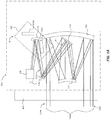
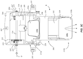
- FIG. 1A is a diagram illustrating an optical system 100 (e.g., a reflective telescope) having a field-of-view switch assembly 102 in a normal, non-bypass position (first position) N
- FIG. 1B is a diagram illustrating the optical system 100 having the field-of-view switch assembly 102 in a bypass position (second position) B.
- the optical system 100 includes a single window 104, a curved primary mirror 106, curved secondary mirror 112, a first flat mirror 114, a second flat mirror 116, a curved tertiary mirror 118, and a camera 128.
- these mirrors can be part of a fore optics assembly of a high-magnification telescope. While this telescope uses three powered mirrors and two flat mirrors, other telescope forms which use 2,4 or 5 powered mirrors and any number of flat mirrors, could use this bypass approach.
- incident beams i.e., light
- incident beams 132a and 132b from an object can be passed through the single aperture or window 104 and are associated with a narrow field-of-view 130a (as the field-of-view switch assembly 102 is shown as being in the normal, non-bypass position (or first position) N).
- Beams 132a and 132b can be caused to impinge or be incident upon the primary mirror 106.
- the primary mirror 106 can be situated relative to the window 104 to receive the beams 132a and 132b, respectively.
- Beams 132a can then be reflected by the primary mirror 106, and concurrently, beams 132b can be reflected by the first flat mirror 114.
- a pair of ray lines is used to represent beams 132a-d (see also FIG. 1B ).
- the beams 132a and 132b can be caused to be incident on the secondary mirror 112, which reflects beams 132a and 132b to the first flat mirror 114, which then reflects beams 132a and 132b to the second flat mirror 116.
- the second flat mirror 116 e.g., a fold mirror
- beams 132a and 132b can be caused to converge/fold and can be reflected as beams 132c, which can be caused to be incident on the tertiary mirror 118.
- the second tertiary mirror 118 can reflect beams to the camera 128, for example, that can receive and transmit signals associated with the beams 132c to a computer system and/or displays (not shown) in a known manner for processing the signals.
- box 128 can be a sub-assembly that includes one detector or a multiplicity of other sensors that receives or that is configured to receive said signals.
- the detector can be any suitable imaging detector or sensor for a telescope, such as a CCD, CMOS, photodiode array, light emitting device or other suitable imaging sensor capable of receiving and transmitting signals pertaining to light rays.
- an optical path P1 defines (in part) the path of the reflected beams 132c to the camera 128, as shown by the dashed lines.
- the beams 132c are shown as being directly received by the camera 128 in FIG. 1A and 1B (and 4A and 4B); however, the beams 132c can be directed to other mirrors or other devices before being received by the camera 128, for instance, depending on the particular application and type of detector and system employed.
- the field-of-view switch assembly 102 of FIG. 1A (in the normal, non-bypass position N) further comprises a first diverter mirror 134a and a second diverter mirror 134b.
- the diverter mirrors 134a and 134b do not receive, and are not reflective of, any of the beams 132a-c of FIG. 1A , as these are in a stowed or inactive configuration (e.g., see FIG. 3A and 4A ).
- the diverter mirrors 134a and 134b can be situated so as to straddle the optical path P1. That is, the diverter mirrors 134a and 134b can be spatially positioned from each other on either side of the beams 132c (i.e., the optical path P1) (see e.g., FIG. 4A ).
- the field-of-view switch assembly 102 is shown as being in the bypass position B, which accommodates a wide field-of view 130b.
- the wide field-of view 130b and the narrow field-of view 130a are directed through the same single aperture or window 104.
- incident beams 132d from an object are passed through the single window 104 and are associated with the wide field-of view 130b.
- beams 132d can be caused to be incident upon, and reflected by the second diverter mirror 134b and subsequently incident upon the first diverter mirror 134a.
- the first diverter mirror 134a then reflects beams 132d to the camera 128 for receiving and transmitting signals associated with the beams 132d.
- the diverter mirrors 134a are in a deployed or active configuration (see e.g., FIG. 3B and 4B ), and thereby shield or block the beams 132c ( FIG. 1 ) that would otherwise be reflected from the tertiary mirror 118.
- the beams 132d comprise or are directed through an optical path P2, as illustrated by the dashed lines, which is different from the optical path P1 of FIG. 1A with the diverter mirrors 134a and 134b in a stowed position.
- the field-of-view switch assembly 102 when the field-of-view switch assembly 102 is moved from the normal, non-bypass position N ( FIG. 1A ) to the bypass position B ( FIG. 1B ), the optical path P1 is redirected (from the same single window 104) by the switch assembly 102 to the camera 128.
- the field-of-view switch assembly 102 is configured to vertically translate the optical path such that the optical path is redirected approximately 180 degrees when in the bypass position (such as illustrated by the pair of 90 degree symbols on the optical path P2 of FIG. 4B ).
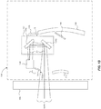
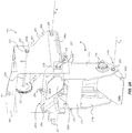
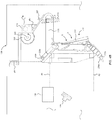
- FIGS. 2A-4B show various views of a field-of-view switch assembly 202, as one example implementation of the field-of-view switch assembly 102 of the system 100 (see also FIGS. 1A and 1B ).
- FIG. 2A shows a front right isometric view
- FIG. 2B shows a front left isometric
- FIG. 2C shows a rear right isometric view (all showing the field-of-view switch assembly 202 in the bypass position B).
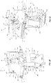
- FIG. 3A is a left side view of the field-of-view switch assembly in a non-bypass position
- FIG. 3B is a left side view of the field-of-view switch assembly in the bypass position;
- FIG. 3C is a front view of the field-of-view switch assembly in the bypass position;
- FIG. 4A is a right side cross sectional view of the field-of-view switch assembly in the non-bypass position; and
- FIG. 4B is a left side cross sectional view of the field-of-view switch assembly in the bypass position.
- the field-of-view switch assembly 202 can comprise a support structure 204 attached to a portion of a reflective telescope, for example (see FIGS. 2A and 3A ). In this manner, the support structure 204 can be secured to a chassis 201 or other support structure of a reflective telescope of the optical system 100 (e.g. see FIG. 4A ), which is further discussed below.
- the field-of-view switch assembly 202 can comprise a mount 206 movably coupled to the support structure 204. In one aspect, the mount 206 can be pivotally coupled to the support structure 204 about a retainer pin 209 ( FIG. 2A ) and an azimuth cam 252 ( FIGS.
- the retainer pin 209 can be part of an inner race flange bearing configuration between the mount 206 and the support structure 204, for instance. Other suitable coupling devices can be used to facilitate said pivotal movement.
- the support structure 204 can comprise a pair of parallel arms 208a and 208b that extend from a body section 210 of the mount 206 (e.g., FIGS. 2A and 2B ).
- the body section 210 can comprise an upper support region 212a and an opposing lower support region 212b, and a pair of parallel side panels 214a and 214b formed between the upper and lower support regions 212a and 212b.
- a lateral cross member 216 is formed between the side panels 214a and 214b to provide structural stability for the mount 206 and the attached mirrors (see discussion below).
- the support structure 204 can be secured to the chassis 201 ( FIG.
- attachment devices 207 can be threaded fasteners, bolts, alignment pins, threaded pins or other suitable devices that can be implemented to attach a sub-assembly housing/frame to a system telescope chassis, for example.
- the field-of-view switch assembly 202 can comprise a four-bar linkage mechanism to facilitate actuation of the mount 206 between the non-bypass position N ( FIGS. 3A and 4A ) and the bypass position B ( FIGS. 2A-2C , 3B , and 4B ).
- An on-board gearmotor 218 can be attached to the support structure 204 and, although not intending to be limiting in any way, can comprise a drive gear 220 rotatably interfaced (e.g., by gear teeth, belts, pulleys, etc.) to a driven gear 222.
- the on-board gearmotor 218 (e.g., an electric motor with integral gearbox and armature encoder) can be clamped to the support structure 204 with a fastener 219 ( FIG. 2C ).
- the on-board gearmotor 218 can be attached directly to the switch assembly 202, which reduces or minimizes impact forces on the internal components of the gearmotor 218, for instance.
- the drive gear 220 can be a metallic pinion gear and the driven gear 222 can be a plastic gear with a clamping hub that interfaces with the drive gear 220 in a typical manner.
- a torsional shaft 224 can be secured to the driven gear 222 and can be rotatably coupled at one end of the torsional shaft 224 through a bearing 227 on left side 226a of the support structure 204 and retained with a screw 225 or other retaining device ( FIG. 2C ).
- the other end of the torsional shaft 224 can similarly be rotatably coupled to the support structure 204 through a bearing 227 of a right side 226b of the structural support 204 and retained with a similar screw 225 ( FIG. 2A ).
- the torsional shaft 224 can be comprised of metal (or plastic) that is suitably shaped and sized (e.g., an elongated rod) and that acts as a torsion spring to absorb energy when the mount 206 is actuated (see further discussion below).
- a crank device 228 can be clamped (or otherwise attached) via a slot 229 that receives the torsional shaft 224 ( FIG. 2B ) at an opposing end of the torsional shaft 224 from the driven gear 222.
- the crank device 228 can be clamped to the torsional shaft 224 by a pair of fasteners 231 (e.g., bolts and nuts, threaded bolt, etc.).
- the crank device 228 is adjustable longitudinally along the shaft 224.
- the crank device 228 is positioned distally from the driven gear 222 along the length of the torsional shaft 224.
- the torsional shaft 224 is allowed to act as a torsional spring where a rotational torque/force is exerted on one end (driven gear 222), and a resistance torque/force is exerted on the other end (by the crank device 228).
- a rotational torque/force is exerted on one end (driven gear 222)
- a resistance torque/force is exerted on the other end (by the crank device 228).
- an amount of energy is absorbed by the torsional shaft 224 when the driven crank device 228 impacts its travel stops 256.
- This facilitates operation of the on-board motor 218 at maximum power capacity to minimize switching duration times of the mount 206 and attached diverter mirrors 232a and 232b.
- a range of maximum power of the on-board motor 218 can be between 1 and 3 Watts
- the switching duration time can be between 0.75 and 2.0 seconds.
- the torsional spring rate is controlled by the diameter of the shaft 224.
- Spring rate is determined the intermittent load rating of the gearmotor 218. The spring rate is reduced so that the kinetic energy of the gearmotor armature running a no-load speed is equal to the wound up torsion shaft potential energy just as the armature angular velocity is decelerated to zero and the torque specification is not exceeded.
- a spring link 230 can be rotatably coupled between the crank device 228 and the mount 206 about two degrees of rotational movement ( FIGS. 3A and 3B ).
- the spring link 230 can have an aperture at one end that is rotatably coupled to a pin 233a of the crank device 228.
- the other end of the spring link 230 can have an aperture that is rotatably coupled to the mount 206 in a similar manner. That is, the mount 206 can have a pin 233b that rotatably receives the aperture of the other end of the spring link 230, as illustrated by the rotation arrow adjacent pin 233b on FIG. 3A and on FIG. 3B .
- the spring link 230 can be comprised of a rigid or semi-rigid material (e.g., certain metals like steel, aluminum, or glass filled plastic etc.) and can be shaped in an arc toward the front of the switch ( FIG. 3B ) to provide an amount of deflection or compliance that generates a "spring effect" that locks the crank device 228 against its travel stop 256 when the mount 206 is in either bypass or non-bypass positions.
- a rigid or semi-rigid material e.g., certain metals like steel, aluminum, or glass filled plastic etc.
- the four-bar linkage mechanism can comprise respective interface/linkage positions of the drive gear 220, driven gear 222, the torsional shaft 224, the crank device 228, and the spring link 230.
- the on-board gearmotor 218 can be activated and caused to rotate the drive gear 220 in a counter-clockwise manner, as shown by the arrow associated with the drive gear 220 on FIG. 3A .
- the on-board gearmotor 218 can be an electric motor electrically controlled by an electronics controller (not shown) and electrically coupled to a power source (e.g., a battery, or other power source) of an overall telescope system, for example.
- the electronics controller can be controlled by a human operator, or by a computer system that causes the electronics controller to activate the on-board gearmotor 218 (i.e., rotate the drive gear 220 in either rotational directions). Therefore, counter-clockwise rotation of the drive gear 220 (about axis M; see FIG. 2C ) causes clockwise rotation ( FIG. 3A ) of the driven gear 222 about axis D (as shown by the rotational arrows associated with driven gear 222 of FIGS.
- the on-board gearmotor 218 can be caused to rotate clockwise, which causes the mount 206 to rotate upwardly to the non-bypass position N, in an opposite manner as described above with utilizing the components of the four-bar linkage mechanism.
- a first diverter mirror 232a can be attached to the mount 206 about the upper support portion 212a, and a second diverter mirror 232b can be attached to the mount 206 about the lower support portion 212b.
- the first diverter mirror 232a can be secured to the mount 206 by compliant fasteners 234 on a back side of the first diverter mirror 232a ( FIGS. 2A , 2B , and 4A ).
- the compliant fasteners 234 can be a suitable mirror fastener with a coil spring coupled between the fastener head and the mirror to minimize mirror surface figure change to manufacturing imperfections in the mating surfaces, for instance.
- the second diverter mirror 232b can be pivotally coupled to the lower support portion 212b about mounting devices 236 (shoulder screw retained ball bearing) on either side of the second diverter mirror 232b, as illustrated by the rotational arrows associated with mounting device 236 of FIG. 3A and 3B .
- the mounting devices 236 can each be rotatably received through apertures of the mount 206 and attached to the mirror 232b through bores or other suitable attachment features of the mirror.
- each mounting device 236 can be part of an inner race flange bearing arrangement between the mount 206 and the second diverter mirror 232b.
- the first diverter mirror 232a can have a reflective surface 238a and the second diverter mirror 232b can have a reflective surface 238b.
- the first diverter mirror 232a can be mounted at an angle such that its reflective surface 238a is optically incident with the reflective surface 238b of the second diverter mirror 232b (e.g., the mirrors can be nominally mounted at approximately a 90 degree angle relative to their reflective surfaces).
- Each mirror can be any suitable mirror, such as an optical mirror comprised of aluminum or other mirrors used in high-magnification telescope systems, for example.
- a dynamic shutter 240 is movably coupled to the mount 206 and configured to shield the reflective surface 238b from stray light rays when the mount 206 is moved to the non-bypass position N.
- the dynamic shutter 240 is also configured to expose the reflective surface 238b of the second diverter mirror 232b when the mount 206 is moved to the bypass position B.
- the dynamic shutter 240 can comprise a non-reflective shielding panel 242 that covers the reflective surface 238b when in the non-bypass position N.
- the shielding panel 242 does not have to cover surface area the same or larger than that of the second diverter mirror 232b (see FIG. 2C and 3C ); it only needs to be large enough prevent stray light for the non-bypass position.
- An elongated link member 244 can be pivotally linked between the mount 206 and the dynamic shutter 240 to facilitate rotational movement of the dynamic shutter 240 when the mount 206 is actuated ( FIGS. 2B-3B and 4A ).
- the elongated link member 244 can have a first end 246a ( FIGS. 2C and 4A ) with an aperture pivotally coupled to the structural support 204 by a shoulder screw arrangement through said aperture (or via other suitable devices that retain and facilitate rotational movement of the link member 244 about the structural support 204). This facilitates rotation of the first end 246a, as shown by the rotational arrows associated with the first end 246a on FIG. 3A .
- a second end 246b of the elongated link member 244 can be pivotally coupled to a pivot portion 248, formed of the dynamic shutter 240 (see FIGS. 2B, 2C , 3A , and 3B ).
- the pivot portion 248 can be formed with and extend from the dynamic shutter 240 in a direction along a length of the shielding panel 242.
- the pivot portion 248 can comprise a cylindrical protrusion that rotatably receives an aperture at the second end 246b (is retained by a pan head screw) of the elongated link member 244 to allow pivotal movement between the dynamic shutter 240 and the link device 244, as illustrated by the rotational arrows associated with the pivot portion 248 of FIG. 3A .
- the pivot portion 248 (of the dynamic shutter 240) comprises an aperture that receives a mounting device 250 (e.g., a shoulder screw) that retains and pivotally couples the dynamic shutter 240 to the mount 206 adjacent the second diverter mirror 232b ( FIG. 2C , 3A , and 3B ).
- the mounting device 250 can be a shoulder screw fastener that is fastened through a bore in the mount 206 and rotational coupled to the pivot portion 248 about its aperture, as illustrated on FIG. 2C .
- the elongated link member 244 is caused to rotate downwardly relative to the support structure 204 (about end 246a of link member 244).
- This causes a pulling force on the pivot portion 248 (of the dynamic shutter 240) that rotates it upwardly relative to the link member 244, which therefore concurrently rotates the shielding panel 242 upwardly and away from the reflective surface 238b of the second diverter mirror 232b to expose the reflective surface 238b to light rays.
- the dynamic shutter 240 is automatically moved between a shielding position S and a mirror exposing position E (e.g., FIG. 4A and 4B ).
- rotational movement of the dynamic shutter 240 occurs automatically by virtue of activating and rotating the mount 206.
- the first diverter mirror 232a and the second diverter mirror 232b are supported such that they straddle the optical path P1 (e.g., see also discussion of FIG. 1A ).
- the first diverter mirror 232a can be positioned spatially and vertically above the optical path P1
- the second diverter mirror 232b can be positioned spatially and vertically below the optical path P1 (although the mirrors can straddle the optical path about any three dimensional orientation on any sides of the path).
- This "straddle" configuration allows for a more compact field-of-view switch mechanism compared to systems that do not have a pair of diverter mirrors on either side of an optical path. Therefore, the diverter mirrors 232a and 232b allow beams (not shown here, but see FIG. 1A ) of the optical path P1 to be reflected from the second flat mirror 116 to the tertiary mirror 118, and ultimately to the camera 128 (see FIGS. 1A and 4A ) (both mirrors 116 and 118 are shown schematically and "in space” for illustration purposes, but they would be attached to a telescope system in a suitable manner for statically mounting precision mirrors, for example). Thus, in comparison of the views of FIGS.
- the first diverter mirror 232a when the mount 206 is rotated downwardly (as discussed above), the first diverter mirror 232a is caused to be positioned within, and blocks light rays of, the beams defining the optical path P1.
- the dynamic shutter 240 is automatically rotated upwardly, thereby moving the shielding panel 242 away from the reflective surface 238b of the second diverter mirror 232b to uncover and expose the reflective surface 238b.
- the second diverter mirror 232b being in a position and angle directed toward the single window 104, reflects beams (e.g., from a wide field of view) upwardly at approximately 90 degrees toward the first diverter mirror 232a.
- the field-of-view switch assembly 202 can be configured to vertically translate and redirect the optical path approximately 180 degrees when in the bypass position B, and through the single window 104 ( FIG. 1B ).
- the field-of-view switch assembly 202 comprises an azimuth cam 252 coupled between the mount 206 and the support structure 204 about the left side 226a at the left parallel arm 208a of the mount 206 ( FIG. 2C , 3A , and 3B ).
- the azimuth cam 252 is an adjustment device and is configured to facilitate adjustment of the mount 206 and the diverter mirrors 232a and 232b in azimuth (for illustration, see the azimuth adjustment arrows on the second diverter mirror 232b of FIG. 3C ).
- Azimuth cams are well known and will not be discussed in great detail.
- the azimuth cam 252 can have an off-center axis body that is adjustable by an operator using a tool to loosen the azimuth cam 252, wherein the mount 206 can be set to a desired azimuth angle about the azimuth cam 252, and then the azimuth cam 252 tightened to ready the mount 206 for use.
- axis A of the mount 204 can be adjusted in two directions (x and y directions), as exemplified by the dashed center lines of axis Y on FIG. 2C , to adjust for azimuth of the mount 204 and its diverter mirrors.
- an elevation cam 254 can be secured to the right side panel 214a of the mount 206 and positioned through an aperture of the mount 206 adjacent the reflective surface 238b of the second diverter mirror 232b ( FIG. 2A , 2B , and 3C ).
- the second diverter mirror 232b is pivotally mounted to the mount 206 (as discussed above) about a central axis X of the second diverter mirror 232b by mounting pins 236 ( FIG. 2A and 2B ) on either side of the second diverter mirror 232b, such that the second diverter mirror 232b is pivotable about axis X ( FIG. 2B ) to adjust for elevation of the second reflective surface 238b (see FIG.
- the elevation cam 254 can have an off-center axis body that can be loosened and rotated (like the azimuth cam), which causes a radial surface of the cam 254 to contact or bias the reflective surface 238b in a desired direction (down or up), which causes the second diverter mirror 232b to pivot upwardly or downwardly to a desired elevation angle. Then the elevation cam 254 can be tightened and set to its desired position for alignment of the second diverter mirror 232b (as illustrated by the arrow adjacent cam 254 on FIG. 2A ).
- the mirror elevation position uses a spring to preload the mirror 232b against the adjustment cam 254.
- Preloaded helical coils or other types of springs or spring-like members can be incorporated in each of the azimuth cam 252 ( FIG. 2B ) and the retainer pin 209 ( FIG. 2A ) at locations between the mount 206 and the support structure 204 in a manner to cause axial preloaded forces against the mount 206 to create a duplex pair-type bearing using deep groove radial contact bearings.
- Similar preloaded helical coil or other types of springs or spring-like members can be incorporated at the side interfaces (about mounting pins 236) between the mount 206 and the second diverter mirror 232b in a manner to cause axial preloaded forces against the mirror 232b to create a duplex pair-type bearing using deep groove radial contact bearings.
- Similar springs can be used in conjunction with the rotational mounting interface between the mount 206 and the support structure 204 when adjusting the azimuth cam 252 to cause a biasing force against the force of an individual rotating the azimuth cam 252.
- Adjustment devices such as azimuth and elevation cams are known in the industry and will not be discussed in greater detail, but it will be appreciated that the azimuth and elevation cams 252 and 254 are adjustable by an operator for boresight adjustment of the second diverter mirror 232b to a desired position in both azimuth and elevation, as illustrated by the boresight arrows of FIGS. 3B and 3C of the second diverter mirror 232b.
- Stop members 256 may be attached to the support structure 204 (e.g., through apertures) about various locations through walls or panels of the support structure 204, as shown on FIGS. 2A-3C .
- the stop members 256 can each extend inwardly towards the center of the support structure 204 to act as stops against the mount 204 when actuated to the bypass position B.
- the stop members 256 can have an adjustable off-center axis body for adjustment (i.e., to account for any azimuth adjustments of the azimuth cam 252).
Landscapes
- Physics & Mathematics (AREA)
- General Physics & Mathematics (AREA)
- Optics & Photonics (AREA)
- Spectroscopy & Molecular Physics (AREA)
- Astronomy & Astrophysics (AREA)
- Multimedia (AREA)
- Engineering & Computer Science (AREA)
- Signal Processing (AREA)
- Telescopes (AREA)
- Studio Devices (AREA)
- Optical Communication System (AREA)
- Instruments For Viewing The Inside Of Hollow Bodies (AREA)
- Mounting And Adjusting Of Optical Elements (AREA)
Claims (15)
- Optisches System (100), das Folgendes umfasst:ein einzelnes Fenster (104);einen Detektor (128);eine optische Anordnung (106, 112, 114, 116, 118), die Lichtstrahlen von einem ersten, schmalen Sichtfeld (130a) durch einen ersten Strahlverlauf (P1) zu dem Detektor reflektiert;eine Sichtfeldschalteranordnung (102, 202), die Folgendes umfasst:eine Halterung (206), die mit der optischen Anordnung beweglich gekoppelt ist, wobei die Halterung zwischen einer Nicht-Bypass-Position (N) und einer Bypass-Position (B) wahlweise beweglich ist;einen ersten Umlenkspiegel (134a, 232a), der an der Halterung angebracht ist;einen zweiten Umlenkspiegel (134b, 232b), der an der Halterung angebracht ist, wobei der erste und der zweite Umlenkspiegel konfiguriert sind, wenn sie sich in der Nicht-Bypass-Position befinden, um Lichtstrahlen (132a-132c) durch den ersten Strahlverlauf nicht zu empfangen und diese nicht zu reflektieren, und um das erste Sichtfeld zu umgehen und ein zweites, weites Sichtfeld (130b) zu verschieben, wenn sie von der Nicht-Bypass-Position in die Bypass-Position bewegt werden, wobei dadurch Lichtstrahlen (132d) von dem zweiten Sichtfeld über den ersten und den zweiten Umlenkspiegel durch einen zweiten Strahlverlauf (P2) zu dem Detektor derart umgeleitet werden, dass die Lichtstrahlen durch den zweiten Strahlverlauf durch das einzelne Fenster auf den zweiten Umlenkspiegel direkt einfallen und durch diesen reflektiert werden, und dann auf den ersten Umlenkspiegel direkt einfallen und dann von dem ersten Umlenkspiegel zu dem Detektor direkt reflektiert werden; undeinen dynamischen Verschluss, der mit der Halterung beweglich gekoppelt ist, wobei der dynamische Verschluss (240) konfiguriert ist, um eine reflektierende Oberfläche (238b) des zweiten Umlenkspiegels von Lichtstrahlen abzuschirmen, wenn er sich in der Nicht-Bypass-Position befindet, und um die reflektierende Oberfläche zu belichten, wenn er sich in der Bypass-Position befindet;wobei sowohl das erste Sichtfeld als auch das zweite Sichtfeld durch das einzelne Fenster verlaufen;wobei der erste und der zweite Umlenkspiegel den ersten Strahlverlauf überspannen, wenn sie sich in der Nicht-Bypass-Position befinden; undwobei der erste Umlenkspiegel, wenn er sich in der Bypass-Position befindet, innerhalb des ersten Strahlverlaufs positioniert ist, und wobei dadurch verhindert wird, dass Lichtstrahlen (132c) entlang des ersten Strahlverlaufs, die von dem ersten Sichtfeld zugeordnet sind, zu dem Detektor reflektiert werden.
- System nach Anspruch 1, wobei der dynamische Verschluss mit der Halterung angrenzend an den zweiten Umlenkspiegel schwenkbar gekoppelt ist, wobei der dynamische Verschluss ferner konfiguriert ist, um sich von der reflektierenden Oberfläche automatisch wegzudrehen, wenn die Halterung in die Bypass-Position bewegt wird, und um sich der reflektierenden Oberfläche automatisch zuzudrehen, wenn die Halterung in die Nicht-Bypass-Position bewegt wird, um die reflektierende Oberfläche abzudecken.
- System nach Anspruch 1, wobei die Sichtfeldschalteranordnung ferner eine Gestellstruktur (204) umfasst, wobei die Halterung mit der Gestellstruktur schwenkbar gekoppelt ist, und wobei die Sichtfeldschalteranordnung ferner einen integrierten Motor (218) umfasst, der an der Gestellstruktur angebracht ist und konfiguriert ist, um die Halterung zwischen der Nicht-Bypass-Position und der Bypass-Position zu betätigen.
- System nach Anspruch 3, wobei die Sichtfeldschalteranordnung eine Torsionswelle (224) umfasst, die mit dem integrierten Motor wirkgekoppelt ist und konfiguriert ist, um die Halterung zu drehen, wenn sie durch den integrierten Motor betätigt wird, wobei die Torsionswelle konfiguriert ist, um Schlagkräfte zu absorbieren, die auf den integrierten Motor einwirken, wobei auf diese Weise ein Betrieb des integrierten Motors bei maximaler Leistungskapazität ermöglicht wird, um die Schaltdauern der Halterung und der angebrachten Umlenkspiegel zu minimieren.
- System nach Anspruch 1, wobei die Sichtfeldschalteranordnung einen Azimutnocken (252) umfasst, der mit der Halterung gekoppelt ist, wobei der Azimutnocken einen Körper mit versetzter Achse für eine Azimuteinstellung der Halterung und des ersten und des zweiten Umlenkspiegels umfasst.
- System nach Anspruch 1, wobei die Sichtfeldschalteranordnung einen Höhennocken (254) umfasst, der einen Körper mit versetzter Achse aufweist, der mit dem zweiten Umlenkspiegel für eine Höheneinstellung des zweiten Umlenkspiegels wirkgekoppelt ist.
- System nach Anspruch 1, wobei reflektierende Oberflächen (238a, 238b) des ersten und des zweiten Umlenkspiegels (232a, 232b), wenn sie sich in der Bypass-Position befinden, positioniert sind, um den zweiten Strahlverlauf um ungefähr 180 Grad zu dem Detektor vertikal zu verschieben und umzuleiten.
- System nach Anspruch 1, wobei die Sichtfeldschalteranordnung einen Gelenkviereckantriebsmechanismus umfasst, der konfiguriert ist, um die Halterung über eine Torsionswelle zwischen der Bypass-- und der Nicht-Bypass-Position zu drehen.
- System nach Anspruch 1, wobei das optische System ein Teleskop mit starker Vergrößerung ist.
- Verfahren zum Ermöglichen eines Schaltens zwischen einem ersten, schmalen Sichtfeld (130a) und einem zweiten, weiten Sichtfeld (130b), beide durch ein einzelnes Fenster (104), mit einer Sichtfeldschalteranordnung (102, 202), wobei das Verfahren Folgendes umfasst:Ermöglichen einer Verschiebung von Lichtstrahlen mit einer optischen Anordnung (106, 112, 114, 116, 118), die Lichtstrahlen von einem ersten Sichtfeld zu einem Detektor (128) eines optischen Systems (100) reflektiert, wobei ein erster Strahlverlauf (P1) durch die Lichtstrahlen durch das einzelne Fenster zu dem Detektor definiert ist;Ermöglichen des Schaltens zwischen dem ersten Sichtfeld und einem zweiten Sichtfeld, beide durch das einzelne Fenster, durch Bewegen einer Sichtfeldschalteranordnung des optischen Systems, die den ersten und den zweiten Umlenkspiegel (134a, 134b, 232a, 232b) zwischen einer Nicht-Bypass-Position (N) und einer Bypass-Position (B) umfasst; undErmöglichen des Abschirmens einer reflektierenden Oberfläche (238b) des zweiten Umlenkspiegels von Lichtstrahlen mit einem dynamischen Verschluss (240), wenn die Halterung in die Nicht-Bypass-Position bewegt wird, und Ermöglichen des Belichtens der reflektierenden Oberfläche mit dem dynamischen Verschluss, wenn die Halterung in die Bypass-Position bewegt wird;wobei der erste und der zweite Umlenkspiegel den ersten Strahlverlauf überspannen, wenn sie sich in der Nicht-Bypass-Position befinden;wobei, wenn sich die Sichtfeldschalteranordnung in der Nicht-Bypass-Position befindet, der erste und der zweite Umlenkspiegel keine Lichtstrahlen (132a-132c) durch den ersten Strahlverlauf empfangen und diese nicht reflektieren, und wobei, wenn sich die Sichtfeldschalteranordnung in der Nicht-Bypass-Position befindet, der erste und der zweite Umlenkspiegel Lichtstrahlen (132d) von dem zweiten Sichtfeld durch einen zweiten Strahlverlauf (P2) zu dem Detektor derart umleiten, dass die Lichtstrahlen durch den zweiten Strahlverlauf durch das einzelne Fenster auf den zweiten Umlenkspiegel direkt einfallen und von diesem reflektiert werden, und dann auf den ersten Umlenkspiegel direkt einfallen und dann von dem ersten Umlenkspiegel zu dem Detektor direkt reflektiert werden; undwobei, wenn die Sichtfeldschalteranordnung Lichtstrahlen von dem zweiten Sichtfeld durch den zweiten Strahlverlauf umleitet, der erste Umlenkspiegel innerhalb des ersten Strahlverlaufs positioniert ist, und wobei dadurch verhindert wird, dass Lichtstrahlen entlang des ersten Strahlverlaufs, die von dem ersten Sichtfeld zugeordnet werden, zu dem Detektor reflektiert werden.
- Verfahren nach Anspruch 10, wobei das Ermöglichen des Schaltens das Ermöglichen einer Bewegung einer Halterung (206) der Sichtfeldschalteranordnung umfasst, wobei die Halterung den ersten Umlenkspiegel und den zweiten Umlenkspiegel innerhalb des ersten Strahlverlaufs positioniert, wenn die Halterung von einer Nicht-Bypass-Position in eine Bypass-Position bewegt wird, um die Lichtstrahlen durch den zweiten Strahlverlauf umzuleiten.
- Verfahren nach Anspruch 11, das ferner das Ermöglichen des Absorbierens von Schlagkräften umfasst, die auf einen integrierten Motor (218) mit einer Torsionswelle (224) der Sichtfeldschalteranordnung ausübbar sind, wenn die Halterung zwischen der Nicht-Bypass- und der Bypass-Position bewegt wird, wobei die Torsionswelle mit der Halterung drehbar gekoppelt ist und durch den integrierten Motor angetrieben wird, um die Halterung zu drehen.
- Verfahren nach Anspruch 11, wobei das Ermöglichen des Schaltens ferner Folgendes umfasst:Ermöglichen der Umleitung des Strahlverlaufs um ungefähr 180 Grad mit dem ersten und dem zweiten Umlenkspiegel, wenn sie sich in der Bypass-Position befinden.
- Verfahren nach Anspruch 11, das ferner das Ermöglichen des Überspannens des Strahlverlaufs mit den Umlenkspiegeln umfasst, wenn sie sich in der Nicht-Bypass-Position befinden.
- Verfahren nach Anspruch 11, wobei das Ermöglichen des Schaltens ferner das Ermöglichen einer Betätigung der Halterung über einen Gelenkviereckantriebsmechanismus der optischen Schalteranordnung umfasst, um die Halterung zwischen der Nicht-Bypass- und der Bypass-Position zu schwenken.
Applications Claiming Priority (2)
| Application Number | Priority Date | Filing Date | Title |
|---|---|---|---|
| US15/370,766 US10761307B2 (en) | 2016-12-06 | 2016-12-06 | Bypass optical switch and methods |
| PCT/US2017/055176 WO2018106332A1 (en) | 2016-12-06 | 2017-10-04 | Bypass optical switch and methods |
Publications (2)
| Publication Number | Publication Date |
|---|---|
| EP3552051A1 EP3552051A1 (de) | 2019-10-16 |
| EP3552051B1 true EP3552051B1 (de) | 2021-03-10 |
Family
ID=60183112
Family Applications (1)
| Application Number | Title | Priority Date | Filing Date |
|---|---|---|---|
| EP17790896.9A Active EP3552051B1 (de) | 2016-12-06 | 2017-10-04 | Optischer bypass-schalter und verfahren |
Country Status (5)
| Country | Link |
|---|---|
| US (1) | US10761307B2 (de) |
| EP (1) | EP3552051B1 (de) |
| JP (1) | JP6824412B2 (de) |
| IL (1) | IL266816B2 (de) |
| WO (1) | WO2018106332A1 (de) |
Families Citing this family (8)
| Publication number | Priority date | Publication date | Assignee | Title |
|---|---|---|---|---|
| US11099371B2 (en) | 2017-12-12 | 2021-08-24 | Raytheon Company | Telescope bypass mirror mechanism with minimized stow volume |
| US11360246B1 (en) * | 2018-03-19 | 2022-06-14 | Wavefront Research, Inc. | Configurable afocal imager system |
| CN110850592B (zh) * | 2019-11-12 | 2022-03-01 | 中国航空工业集团公司洛阳电光设备研究所 | 一种具有扫描功能的激光电视红外三波段光学系统 |
| JP7679618B2 (ja) | 2020-11-12 | 2025-05-20 | セイコーエプソン株式会社 | 測色装置 |
| JP7631747B2 (ja) | 2020-11-12 | 2025-02-19 | セイコーエプソン株式会社 | 測色装置 |
| JP7707522B2 (ja) | 2020-11-12 | 2025-07-15 | セイコーエプソン株式会社 | 測色装置 |
| JP7753644B2 (ja) | 2021-03-04 | 2025-10-15 | セイコーエプソン株式会社 | 測色装置 |
| JP7773125B2 (ja) | 2021-10-25 | 2025-11-19 | セイコーエプソン株式会社 | 測色装置 |
Citations (1)
| Publication number | Priority date | Publication date | Assignee | Title |
|---|---|---|---|---|
| US20060146399A1 (en) * | 2005-01-05 | 2006-07-06 | Raytheon Company | Optical system having three fields of view using two all-reflective optical modules |
Family Cites Families (20)
| Publication number | Priority date | Publication date | Assignee | Title |
|---|---|---|---|---|
| US4469396A (en) | 1980-10-08 | 1984-09-04 | Barr & Stroud Limited | Afocal dual magnification refractor telescopes |
| US4567782A (en) * | 1981-04-06 | 1986-02-04 | General Dynamics Pomona Division | Compound parallelogram four-bar linkage |
| US4877317A (en) * | 1983-10-03 | 1989-10-31 | Texas Instruments Incorporated | Dual field of view catadioptric optical system |
| US4763991A (en) * | 1987-08-10 | 1988-08-16 | Litton Systems, Inc. | Adjustable six degree of freedom mount for optical components |
| US5009494A (en) * | 1990-05-21 | 1991-04-23 | Hughes Aircraft Company | Wide field all-reflective multiple field of view telescope |
| US5227923A (en) | 1991-09-30 | 1993-07-13 | Hughes Aircraft Company | Dual-field of view reflective reimaging telescope |
| US5477395A (en) | 1994-11-14 | 1995-12-19 | Hughes Aircraft Company | Two nested all-reflective afocal telescopes providing four fields of view |
| GB9711366D0 (en) * | 1997-06-02 | 1997-07-30 | Pilkington Perkin Elmer Ltd | Optical imaging system |
| US5907433A (en) | 1997-06-16 | 1999-05-25 | Versatron Corporation | Compact variable field of view optical system |
| DE19904687A1 (de) * | 1999-02-05 | 2000-08-10 | Zeiss Carl Fa | Richtbare Teleskopanordnung |
| US6084727A (en) | 1999-04-28 | 2000-07-04 | Raytheon Company | All-reflective field-switching optical imaging system |
| FR2833717B1 (fr) * | 2001-12-14 | 2004-02-20 | Thales Sa | Combinaison optique multichamp de type cassegrain |
| US6970286B1 (en) | 2004-06-23 | 2005-11-29 | Corning Incorporated | Multiple field of view reflective telescope |
| TW200812198A (en) * | 2006-08-21 | 2008-03-01 | Sunonwealth Electr Mach Ind Co | Shock-prevention structure of motor |
| CN200990537Y (zh) * | 2006-12-18 | 2007-12-12 | 中山大洋电机股份有限公司 | 一种外转子电机轴与定子的减振连接装置 |
| US8154712B2 (en) | 2008-07-23 | 2012-04-10 | Corning Incorporated | Insertion of laser path in multiple field of view reflective telescope |
| US7952799B2 (en) * | 2009-06-19 | 2011-05-31 | Corning Incorporated | Extreme broadband compact optical system with multiple fields of view |
| US8427744B2 (en) | 2009-10-12 | 2013-04-23 | Raytheon Company | All-reflective relayed focal telescope derived from the first two mirrors of an afocal three-mirror anastigmat |
| US9122039B2 (en) | 2013-03-06 | 2015-09-01 | Raytheon Company | Compact internal field of view switch and pupil relay |
| US9310601B1 (en) | 2014-08-13 | 2016-04-12 | Lockheed Martin Corporation | System and method for converting between Keplerian and Galilean telescope magnification |
-
2016
- 2016-12-06 US US15/370,766 patent/US10761307B2/en active Active
-
2017
- 2017-10-04 JP JP2019530006A patent/JP6824412B2/ja active Active
- 2017-10-04 EP EP17790896.9A patent/EP3552051B1/de active Active
- 2017-10-04 WO PCT/US2017/055176 patent/WO2018106332A1/en not_active Ceased
-
2019
- 2019-05-22 IL IL266816A patent/IL266816B2/en unknown
Patent Citations (1)
| Publication number | Priority date | Publication date | Assignee | Title |
|---|---|---|---|---|
| US20060146399A1 (en) * | 2005-01-05 | 2006-07-06 | Raytheon Company | Optical system having three fields of view using two all-reflective optical modules |
Also Published As
| Publication number | Publication date |
|---|---|
| IL266816A (en) | 2019-07-31 |
| US10761307B2 (en) | 2020-09-01 |
| JP6824412B2 (ja) | 2021-02-03 |
| EP3552051A1 (de) | 2019-10-16 |
| JP2019537069A (ja) | 2019-12-19 |
| US20180157018A1 (en) | 2018-06-07 |
| WO2018106332A1 (en) | 2018-06-14 |
| IL266816B1 (en) | 2023-01-01 |
| IL266816B2 (en) | 2023-05-01 |
Similar Documents
| Publication | Publication Date | Title |
|---|---|---|
| EP3552051B1 (de) | Optischer bypass-schalter und verfahren | |
| JP6545392B2 (ja) | 光路切換装置 | |
| EP2008141B1 (de) | Optisches pointierbares system mit coude-optik mit kurzer kardanweglänge | |
| EP1308748B1 (de) | Optischer Sensor mit einem Sensorstrahlengang und einem parallel zu der optischen Achse des Sensorstrahlenganges emittierenden Laserstrahler | |
| US9285581B2 (en) | Optical scanning devices and systems | |
| US5907433A (en) | Compact variable field of view optical system | |
| US6084727A (en) | All-reflective field-switching optical imaging system | |
| JP4326946B2 (ja) | 多数の回転望遠鏡サブアセンブリを有する走査センサシステム | |
| EP3203296A1 (de) | Punktsymmetrischer wechsler für optische elemente | |
| US8385733B2 (en) | Image pickup apparatus | |
| CN110673291A (zh) | 两档定焦、反射镜切换变焦、高清镜头的结构及实现方法 | |
| JP2001512586A (ja) | 光学装置 | |
| JP3432677B2 (ja) | 赤外線映像装置の視野切換機構 | |
| EP1622758A2 (de) | Kardananordnung für optisches abbildungssystem | |
| JPS5932033B2 (ja) | 工業用テレビカメラ | |
| US4677288A (en) | Optical turret | |
| US9989753B2 (en) | Centrosymmetric changer for optical elements | |
| US6513940B1 (en) | Field-of-view switching and focusing system of common-optical-path periscope | |
| DE102007044766B4 (de) | Vorrichtung zur Erfassung einer Objektszene | |
| US11099371B2 (en) | Telescope bypass mirror mechanism with minimized stow volume | |
| US11774732B2 (en) | Continuous zoom afocal lens assembly | |
| JP6736700B2 (ja) | レンズ組立体のための位置整合機構 | |
| RU2275662C2 (ru) | Телескоп | |
| US10989898B2 (en) | Quad-axis rotatable coudé path | |
| EP2798390B1 (de) | Optisches schaltsystem |
Legal Events
| Date | Code | Title | Description |
|---|---|---|---|
| STAA | Information on the status of an ep patent application or granted ep patent |
Free format text: STATUS: UNKNOWN |
|
| STAA | Information on the status of an ep patent application or granted ep patent |
Free format text: STATUS: THE INTERNATIONAL PUBLICATION HAS BEEN MADE |
|
| PUAI | Public reference made under article 153(3) epc to a published international application that has entered the european phase |
Free format text: ORIGINAL CODE: 0009012 |
|
| STAA | Information on the status of an ep patent application or granted ep patent |
Free format text: STATUS: REQUEST FOR EXAMINATION WAS MADE |
|
| 17P | Request for examination filed |
Effective date: 20190705 |
|
| AK | Designated contracting states |
Kind code of ref document: A1 Designated state(s): AL AT BE BG CH CY CZ DE DK EE ES FI FR GB GR HR HU IE IS IT LI LT LU LV MC MK MT NL NO PL PT RO RS SE SI SK SM TR |
|
| AX | Request for extension of the european patent |
Extension state: BA ME |
|
| STAA | Information on the status of an ep patent application or granted ep patent |
Free format text: STATUS: EXAMINATION IS IN PROGRESS |
|
| 17Q | First examination report despatched |
Effective date: 20200130 |
|
| DAV | Request for validation of the european patent (deleted) | ||
| DAX | Request for extension of the european patent (deleted) | ||
| GRAP | Despatch of communication of intention to grant a patent |
Free format text: ORIGINAL CODE: EPIDOSNIGR1 |
|
| STAA | Information on the status of an ep patent application or granted ep patent |
Free format text: STATUS: GRANT OF PATENT IS INTENDED |
|
| INTG | Intention to grant announced |
Effective date: 20201015 |
|
| RIN1 | Information on inventor provided before grant (corrected) |
Inventor name: MILLER, KIRK A. |
|
| GRAS | Grant fee paid |
Free format text: ORIGINAL CODE: EPIDOSNIGR3 |
|
| GRAA | (expected) grant |
Free format text: ORIGINAL CODE: 0009210 |
|
| STAA | Information on the status of an ep patent application or granted ep patent |
Free format text: STATUS: THE PATENT HAS BEEN GRANTED |
|
| AK | Designated contracting states |
Kind code of ref document: B1 Designated state(s): AL AT BE BG CH CY CZ DE DK EE ES FI FR GB GR HR HU IE IS IT LI LT LU LV MC MK MT NL NO PL PT RO RS SE SI SK SM TR |
|
| REG | Reference to a national code |
Ref country code: GB Ref legal event code: FG4D |
|
| REG | Reference to a national code |
Ref country code: AT Ref legal event code: REF Ref document number: 1370469 Country of ref document: AT Kind code of ref document: T Effective date: 20210315 Ref country code: CH Ref legal event code: EP |
|
| REG | Reference to a national code |
Ref country code: IE Ref legal event code: FG4D |
|
| REG | Reference to a national code |
Ref country code: DE Ref legal event code: R096 Ref document number: 602017034424 Country of ref document: DE |
|
| REG | Reference to a national code |
Ref country code: LT Ref legal event code: MG9D |
|
| PG25 | Lapsed in a contracting state [announced via postgrant information from national office to epo] |
Ref country code: LT Free format text: LAPSE BECAUSE OF FAILURE TO SUBMIT A TRANSLATION OF THE DESCRIPTION OR TO PAY THE FEE WITHIN THE PRESCRIBED TIME-LIMIT Effective date: 20210310 Ref country code: BG Free format text: LAPSE BECAUSE OF FAILURE TO SUBMIT A TRANSLATION OF THE DESCRIPTION OR TO PAY THE FEE WITHIN THE PRESCRIBED TIME-LIMIT Effective date: 20210610 Ref country code: GR Free format text: LAPSE BECAUSE OF FAILURE TO SUBMIT A TRANSLATION OF THE DESCRIPTION OR TO PAY THE FEE WITHIN THE PRESCRIBED TIME-LIMIT Effective date: 20210611 Ref country code: HR Free format text: LAPSE BECAUSE OF FAILURE TO SUBMIT A TRANSLATION OF THE DESCRIPTION OR TO PAY THE FEE WITHIN THE PRESCRIBED TIME-LIMIT Effective date: 20210310 Ref country code: FI Free format text: LAPSE BECAUSE OF FAILURE TO SUBMIT A TRANSLATION OF THE DESCRIPTION OR TO PAY THE FEE WITHIN THE PRESCRIBED TIME-LIMIT Effective date: 20210310 Ref country code: NO Free format text: LAPSE BECAUSE OF FAILURE TO SUBMIT A TRANSLATION OF THE DESCRIPTION OR TO PAY THE FEE WITHIN THE PRESCRIBED TIME-LIMIT Effective date: 20210610 |
|
| REG | Reference to a national code |
Ref country code: AT Ref legal event code: MK05 Ref document number: 1370469 Country of ref document: AT Kind code of ref document: T Effective date: 20210310 |
|
| REG | Reference to a national code |
Ref country code: NL Ref legal event code: MP Effective date: 20210310 |
|
| PG25 | Lapsed in a contracting state [announced via postgrant information from national office to epo] |
Ref country code: LV Free format text: LAPSE BECAUSE OF FAILURE TO SUBMIT A TRANSLATION OF THE DESCRIPTION OR TO PAY THE FEE WITHIN THE PRESCRIBED TIME-LIMIT Effective date: 20210310 Ref country code: RS Free format text: LAPSE BECAUSE OF FAILURE TO SUBMIT A TRANSLATION OF THE DESCRIPTION OR TO PAY THE FEE WITHIN THE PRESCRIBED TIME-LIMIT Effective date: 20210310 Ref country code: SE Free format text: LAPSE BECAUSE OF FAILURE TO SUBMIT A TRANSLATION OF THE DESCRIPTION OR TO PAY THE FEE WITHIN THE PRESCRIBED TIME-LIMIT Effective date: 20210310 |
|
| PG25 | Lapsed in a contracting state [announced via postgrant information from national office to epo] |
Ref country code: NL Free format text: LAPSE BECAUSE OF FAILURE TO SUBMIT A TRANSLATION OF THE DESCRIPTION OR TO PAY THE FEE WITHIN THE PRESCRIBED TIME-LIMIT Effective date: 20210310 |
|
| PG25 | Lapsed in a contracting state [announced via postgrant information from national office to epo] |
Ref country code: AT Free format text: LAPSE BECAUSE OF FAILURE TO SUBMIT A TRANSLATION OF THE DESCRIPTION OR TO PAY THE FEE WITHIN THE PRESCRIBED TIME-LIMIT Effective date: 20210310 Ref country code: SM Free format text: LAPSE BECAUSE OF FAILURE TO SUBMIT A TRANSLATION OF THE DESCRIPTION OR TO PAY THE FEE WITHIN THE PRESCRIBED TIME-LIMIT Effective date: 20210310 Ref country code: EE Free format text: LAPSE BECAUSE OF FAILURE TO SUBMIT A TRANSLATION OF THE DESCRIPTION OR TO PAY THE FEE WITHIN THE PRESCRIBED TIME-LIMIT Effective date: 20210310 Ref country code: CZ Free format text: LAPSE BECAUSE OF FAILURE TO SUBMIT A TRANSLATION OF THE DESCRIPTION OR TO PAY THE FEE WITHIN THE PRESCRIBED TIME-LIMIT Effective date: 20210310 |
|
| PG25 | Lapsed in a contracting state [announced via postgrant information from national office to epo] |
Ref country code: PL Free format text: LAPSE BECAUSE OF FAILURE TO SUBMIT A TRANSLATION OF THE DESCRIPTION OR TO PAY THE FEE WITHIN THE PRESCRIBED TIME-LIMIT Effective date: 20210310 Ref country code: PT Free format text: LAPSE BECAUSE OF FAILURE TO SUBMIT A TRANSLATION OF THE DESCRIPTION OR TO PAY THE FEE WITHIN THE PRESCRIBED TIME-LIMIT Effective date: 20210712 Ref country code: RO Free format text: LAPSE BECAUSE OF FAILURE TO SUBMIT A TRANSLATION OF THE DESCRIPTION OR TO PAY THE FEE WITHIN THE PRESCRIBED TIME-LIMIT Effective date: 20210310 Ref country code: SK Free format text: LAPSE BECAUSE OF FAILURE TO SUBMIT A TRANSLATION OF THE DESCRIPTION OR TO PAY THE FEE WITHIN THE PRESCRIBED TIME-LIMIT Effective date: 20210310 Ref country code: IS Free format text: LAPSE BECAUSE OF FAILURE TO SUBMIT A TRANSLATION OF THE DESCRIPTION OR TO PAY THE FEE WITHIN THE PRESCRIBED TIME-LIMIT Effective date: 20210710 |
|
| REG | Reference to a national code |
Ref country code: DE Ref legal event code: R097 Ref document number: 602017034424 Country of ref document: DE |
|
| PLBE | No opposition filed within time limit |
Free format text: ORIGINAL CODE: 0009261 |
|
| STAA | Information on the status of an ep patent application or granted ep patent |
Free format text: STATUS: NO OPPOSITION FILED WITHIN TIME LIMIT |
|
| PG25 | Lapsed in a contracting state [announced via postgrant information from national office to epo] |
Ref country code: AL Free format text: LAPSE BECAUSE OF FAILURE TO SUBMIT A TRANSLATION OF THE DESCRIPTION OR TO PAY THE FEE WITHIN THE PRESCRIBED TIME-LIMIT Effective date: 20210310 Ref country code: DK Free format text: LAPSE BECAUSE OF FAILURE TO SUBMIT A TRANSLATION OF THE DESCRIPTION OR TO PAY THE FEE WITHIN THE PRESCRIBED TIME-LIMIT Effective date: 20210310 Ref country code: ES Free format text: LAPSE BECAUSE OF FAILURE TO SUBMIT A TRANSLATION OF THE DESCRIPTION OR TO PAY THE FEE WITHIN THE PRESCRIBED TIME-LIMIT Effective date: 20210310 |
|
| 26N | No opposition filed |
Effective date: 20211213 |
|
| PG25 | Lapsed in a contracting state [announced via postgrant information from national office to epo] |
Ref country code: SI Free format text: LAPSE BECAUSE OF FAILURE TO SUBMIT A TRANSLATION OF THE DESCRIPTION OR TO PAY THE FEE WITHIN THE PRESCRIBED TIME-LIMIT Effective date: 20210310 |
|
| PG25 | Lapsed in a contracting state [announced via postgrant information from national office to epo] |
Ref country code: IT Free format text: LAPSE BECAUSE OF FAILURE TO SUBMIT A TRANSLATION OF THE DESCRIPTION OR TO PAY THE FEE WITHIN THE PRESCRIBED TIME-LIMIT Effective date: 20210310 |
|
| REG | Reference to a national code |
Ref country code: CH Ref legal event code: PL |
|
| PG25 | Lapsed in a contracting state [announced via postgrant information from national office to epo] |
Ref country code: IS Free format text: LAPSE BECAUSE OF FAILURE TO SUBMIT A TRANSLATION OF THE DESCRIPTION OR TO PAY THE FEE WITHIN THE PRESCRIBED TIME-LIMIT Effective date: 20210710 |
|
| REG | Reference to a national code |
Ref country code: BE Ref legal event code: MM Effective date: 20211031 |
|
| PG25 | Lapsed in a contracting state [announced via postgrant information from national office to epo] |
Ref country code: MC Free format text: LAPSE BECAUSE OF FAILURE TO SUBMIT A TRANSLATION OF THE DESCRIPTION OR TO PAY THE FEE WITHIN THE PRESCRIBED TIME-LIMIT Effective date: 20210310 |
|
| PG25 | Lapsed in a contracting state [announced via postgrant information from national office to epo] |
Ref country code: LU Free format text: LAPSE BECAUSE OF NON-PAYMENT OF DUE FEES Effective date: 20211004 Ref country code: BE Free format text: LAPSE BECAUSE OF NON-PAYMENT OF DUE FEES Effective date: 20211031 |
|
| PG25 | Lapsed in a contracting state [announced via postgrant information from national office to epo] |
Ref country code: LI Free format text: LAPSE BECAUSE OF NON-PAYMENT OF DUE FEES Effective date: 20211031 Ref country code: CH Free format text: LAPSE BECAUSE OF NON-PAYMENT OF DUE FEES Effective date: 20211031 |
|
| PG25 | Lapsed in a contracting state [announced via postgrant information from national office to epo] |
Ref country code: IE Free format text: LAPSE BECAUSE OF NON-PAYMENT OF DUE FEES Effective date: 20211004 |
|
| PG25 | Lapsed in a contracting state [announced via postgrant information from national office to epo] |
Ref country code: CY Free format text: LAPSE BECAUSE OF FAILURE TO SUBMIT A TRANSLATION OF THE DESCRIPTION OR TO PAY THE FEE WITHIN THE PRESCRIBED TIME-LIMIT Effective date: 20210310 |
|
| P01 | Opt-out of the competence of the unified patent court (upc) registered |
Effective date: 20230530 |
|
| PG25 | Lapsed in a contracting state [announced via postgrant information from national office to epo] |
Ref country code: HU Free format text: LAPSE BECAUSE OF FAILURE TO SUBMIT A TRANSLATION OF THE DESCRIPTION OR TO PAY THE FEE WITHIN THE PRESCRIBED TIME-LIMIT; INVALID AB INITIO Effective date: 20171004 |
|
| PG25 | Lapsed in a contracting state [announced via postgrant information from national office to epo] |
Ref country code: MK Free format text: LAPSE BECAUSE OF FAILURE TO SUBMIT A TRANSLATION OF THE DESCRIPTION OR TO PAY THE FEE WITHIN THE PRESCRIBED TIME-LIMIT Effective date: 20210310 |
|
| PG25 | Lapsed in a contracting state [announced via postgrant information from national office to epo] |
Ref country code: MT Free format text: LAPSE BECAUSE OF FAILURE TO SUBMIT A TRANSLATION OF THE DESCRIPTION OR TO PAY THE FEE WITHIN THE PRESCRIBED TIME-LIMIT Effective date: 20210310 |
|
| PGFP | Annual fee paid to national office [announced via postgrant information from national office to epo] |
Ref country code: DE Payment date: 20240919 Year of fee payment: 8 |
|
| PGFP | Annual fee paid to national office [announced via postgrant information from national office to epo] |
Ref country code: GB Payment date: 20250923 Year of fee payment: 9 |
|
| PGFP | Annual fee paid to national office [announced via postgrant information from national office to epo] |
Ref country code: FR Payment date: 20250925 Year of fee payment: 9 |
|
| PG25 | Lapsed in a contracting state [announced via postgrant information from national office to epo] |
Ref country code: TR Free format text: LAPSE BECAUSE OF FAILURE TO SUBMIT A TRANSLATION OF THE DESCRIPTION OR TO PAY THE FEE WITHIN THE PRESCRIBED TIME-LIMIT Effective date: 20210310 |