EP3552038B1 - Automatisches aufstellen von hygieneausrüstung - Google Patents
Automatisches aufstellen von hygieneausrüstung Download PDFInfo
- Publication number
- EP3552038B1 EP3552038B1 EP16809361.5A EP16809361A EP3552038B1 EP 3552038 B1 EP3552038 B1 EP 3552038B1 EP 16809361 A EP16809361 A EP 16809361A EP 3552038 B1 EP3552038 B1 EP 3552038B1
- Authority
- EP
- European Patent Office
- Prior art keywords
- hygiene equipment
- piece
- payload data
- information
- processing circuit
- Prior art date
- Legal status (The legal status is an assumption and is not a legal conclusion. Google has not performed a legal analysis and makes no representation as to the accuracy of the status listed.)
- Active
Links
Images

Classifications
-
- G—PHYSICS
- G01—MEASURING; TESTING
- G01S—RADIO DIRECTION-FINDING; RADIO NAVIGATION; DETERMINING DISTANCE OR VELOCITY BY USE OF RADIO WAVES; LOCATING OR PRESENCE-DETECTING BY USE OF THE REFLECTION OR RERADIATION OF RADIO WAVES; ANALOGOUS ARRANGEMENTS USING OTHER WAVES
- G01S13/00—Systems using the reflection or reradiation of radio waves, e.g. radar systems; Analogous systems using reflection or reradiation of waves whose nature or wavelength is irrelevant or unspecified
- G01S13/74—Systems using reradiation of radio waves, e.g. secondary radar systems; Analogous systems
- G01S13/76—Systems using reradiation of radio waves, e.g. secondary radar systems; Analogous systems wherein pulse-type signals are transmitted
-
- G—PHYSICS
- G01—MEASURING; TESTING
- G01S—RADIO DIRECTION-FINDING; RADIO NAVIGATION; DETERMINING DISTANCE OR VELOCITY BY USE OF RADIO WAVES; LOCATING OR PRESENCE-DETECTING BY USE OF THE REFLECTION OR RERADIATION OF RADIO WAVES; ANALOGOUS ARRANGEMENTS USING OTHER WAVES
- G01S5/00—Position-fixing by co-ordinating two or more direction or position line determinations; Position-fixing by co-ordinating two or more distance determinations
- G01S5/02—Position-fixing by co-ordinating two or more direction or position line determinations; Position-fixing by co-ordinating two or more distance determinations using radio waves
- G01S5/10—Position of receiver fixed by co-ordinating a plurality of position lines defined by path-difference measurements, e.g. omega or decca systems
-
- A—HUMAN NECESSITIES
- A47—FURNITURE; DOMESTIC ARTICLES OR APPLIANCES; COFFEE MILLS; SPICE MILLS; SUCTION CLEANERS IN GENERAL
- A47K—SANITARY EQUIPMENT NOT OTHERWISE PROVIDED FOR; TOILET ACCESSORIES
- A47K10/00—Body-drying implements; Toilet paper; Holders therefor
- A47K10/24—Towel dispensers, e.g. for piled-up or folded textile towels; Toilet paper dispensers; Dispensers for piled-up or folded textile towels provided or not with devices for taking-up soiled towels as far as not mechanically driven
-
- A—HUMAN NECESSITIES
- A47—FURNITURE; DOMESTIC ARTICLES OR APPLIANCES; COFFEE MILLS; SPICE MILLS; SUCTION CLEANERS IN GENERAL
- A47K—SANITARY EQUIPMENT NOT OTHERWISE PROVIDED FOR; TOILET ACCESSORIES
- A47K5/00—Holders or dispensers for soap, toothpaste, or the like
-
- G—PHYSICS
- G01—MEASURING; TESTING
- G01S—RADIO DIRECTION-FINDING; RADIO NAVIGATION; DETERMINING DISTANCE OR VELOCITY BY USE OF RADIO WAVES; LOCATING OR PRESENCE-DETECTING BY USE OF THE REFLECTION OR RERADIATION OF RADIO WAVES; ANALOGOUS ARRANGEMENTS USING OTHER WAVES
- G01S13/00—Systems using the reflection or reradiation of radio waves, e.g. radar systems; Analogous systems using reflection or reradiation of waves whose nature or wavelength is irrelevant or unspecified
- G01S13/87—Combinations of radar systems, e.g. primary radar and secondary radar
- G01S13/878—Combination of several spaced transmitters or receivers of known location for determining the position of a transponder or a reflector
Definitions
- the present invention relates to hygiene equipment and to setting up and configuring individual pieces of hygiene equipment. More specifically, the present invention relates to a piece of hygiene equipment that can be arranged to dispense a consumable to a user, and/or to dispose a consumable from a user, and has capabilities to receive and/or transmit radio signals. The present invention also relates to a system formed by two or more corresponding pieces of hygiene equipment.
- Hygiene equipment in the form of, for example, dispensers for various liquids and/or tissues is generally common today in premises that are frequented by many people.
- premises can be office buildings, manufacturing sites, hospitals, airports, train stations, bus terminals, shopping malls, hotels, restaurants, schools, kindergartens, and the like, which all have in common that they are places being visited by a considerable number of people and that hand or body hygiene or cleaning in general is desired at least to some degree. As a consequence, these premises will provide restroom or related facilities for the people working or staying in these premises.
- the mentioned hygiene equipment may be installed in form of soap, foam or towel dispensers, disinfectant (e.g. alcogel etc.) dispensers, toilet paper dispensers, hygiene bag dispensers, dispensers for hygiene products, such as absorbent articles, diapers, incontinence products, and other related devices.
- disinfectant e.g. alcogel etc.
- toilet paper dispensers e.g. a toilet paper dispenser
- hygiene bag dispensers e.g. sonic dispensers
- dispensers for hygiene products such as absorbent articles, diapers, incontinence products, and other related devices.
- hygiene equipment is predominantly present in restroom or toilet facilities.
- such equipment may be found in entrance halls, kitchens, kitchenettes, offices, restaurants, canteens, conference/meeting rooms, receptions, reception areas, elevator, waiting areas, printer rooms and docucenters, gyms, or disposal areas.
- hygiene equipment will be present virtually everywhere, since doctors and caring personnel will need access to such facilities also when not using a restroom or toilet facility.
- a server of, or, connected to a data network can receive and store such notifications in order for allowing service personnel to receive or obtain corresponding indications that a refill needs to be carried out.
- a data network e.g. Internet
- the hygiene equipment may have capabilities to convey signals related to said notification via a wireless radio signal to a recipient station placed sufficiently near to the hygiene equipment.
- nodes within the ad hoc network may have a communication module configured to communicate with the ad hoc network using at least one of room-limited communications and room-transparent communications.
- FIG. 1 shows a schematic view of a piece of hygiene equipment according to an embodiment of the present invention.
- the figure shows a piece of hygiene equipment in the form of a soap, gel, foam, or liquid dispenser 10.
- the dispenser 10 is configured to dispense a consumable to a user in that, for example, a lever 101 is actuated for driving an ejection mechanism 102, which, in turn, ejects an amount 104 of the consumable held in a reservoir 103.
- the consumable may be accordingly liquid or solid soap, a disinfectant liquid/consumable, a foaming liquid etc.
- a user's hand actuating the lever 101 can be provided with the amount 104 of soap, foam, or disinfectant.
- a liquid dispenser is shown, the following details may equally be combined with the respective components of a dispenser for solid substances, tissues, towels, absorbent articles, or other hygiene articles.
- the shown piece of hygiene equipment 10 comprises a processing circuit 111 and a radio circuit 112.
- the latter radio circuit 112 is configured to receive and transmit a radio signal 20 carrying payload data 200.
- the radio circuit 112 can be configured to receive an inbound radio signal 20-1 carrying payload data 200, and to transmit an outbound radio signal 20-0 carrying the payload data 200.
- the processing circuit 111 can be configured to obtain the payload data 200 carried by a received inbound radio signal 20-1 and/or to generate the payload data to be carried by a transmitted outbound radio signal 20-0.
- there is thus envisaged a two-way operation although some embodiments of the present invention may rely and comprise only the configuration for one of the two directions, i.e. the receiving of inbound signals or the transmission of outbound signals.
- the processing circuit 111 is further configured to obtain information on a positional relationship to another device by instructing the radio circuit to receive and/or transmit a radio signal carrying first payload data.
- the information on a positional relationship to another device can comprise information on a distance to the other device, information on a range, information on a 2D or 3D vector pointing to the other device, or on any coordinate position - in relative or in absolute terms - that allows determining a positional relationship to the other device.
- timing information indicating when the radio signal is received and/or transmitted by an antenna coupled to said radio circuit 111 can be obtained.
- the processing circuit 111 can obtain information on when an inbound radio signal reached the receiving antenna 113 and/or when an outbound radio signal leaves the antenna 113 coupled to the radio circuit 112.
- the piece of hygiene equipment 10 may as such comprise the antenna 113 that receives/transmits the radio signal 20 from or into a transmission range.
- the antenna 113 may well be external to the piece of hygiene equipment and as such not comprised by the dispenser 10.
- Said first payload data may be employed to convey information on said timing information for the purpose of ranging and/or positioning. More detailed examples are described elsewhere in the present disclosure.
- the processing circuit 111 is further configured to generate second payload data on the basis of the obtained information on a positional relationship, and to instruct the radio circuit 111 to transmit a radio signal carrying said second payload data.
- the piece of hygiene equipment can determine at least a positional relationship to one other device and can convey information on that determined positional relationship to any recipient in the radio range of the piece of hygiene equipment.
- a piece of hygiene equipment according to an embodiment of the present invention can be installed at a given position, and can automatically determine some kind of a relative position (e.g. one or more distances/ranges) to one or more neighboring devices.
- This information can be collected by some kind of central entity which, in turn, is able to locate the individual pieces of hygiene equipment even in a larger installation.
- the embodiments of the present invention can thus provide the advantage of substantially facilitating the installation of hygiene equipment which is oftentimes installed in large premises and thus comprising usually a considerable number of individual dispensers and related devices.
- a relative positional map can be established within a floating, relative coordinate system. This system can then be anchored in reality or mapped to the real world by defining one or more absolute points, e.g. in terms of real world 3D coordinates.
- the payload data (PD) 200 may generally comprise any suitable data, including information indicating an identification of the piece of hygiene equipment 10, information indicating an identification of an originator/transmitter of an inbound radio signal, information relating to timing information, information indicating a number of use instances of the piece hygiene equipment 10, and/or information indicating a filling state of the consumable in the reservoir 103.
- the processing circuit 111 may be coupled to sensors of the ejection mechanism 102 and/or, respectively, the reservoir 103 so as to be able to generate corresponding payload data.
- the detailed mechanical and/or electronic mechanisms and configurations for dispensing an amount of consumable and detecting use instances and filling states are as such known in the prior arts.
- the embodiments of the present invention are not limited to above mentioned types of information. Therefore, the PD may also comprise or relate to status data, or data on a physical observable like luminosity, light, humidity, temperature and the like may be conveyed. Further examples include data on a refill ID, data on occupancy or movement (by persons and/or equipment), and general content (e.g. messages, commercial images, etc.).
- the specific hitherto mentioned information is conveyed in the form of payload data carried by radio signals in specific modi and phases.
- the operation of the piece of hygiene equipment can be divided into two phases, a first installation phase in which the hygiene equipment is operated in a first mode and a second operation phase in which the hygiene equipment is operated in a second mode.
- the payload may be predominantly identified by the mentioned first and second payload plus, optionally, payload carrying information on timings, originators, identifications and the like.
- the payload may be predominantly identified again by payload carrying information on originators and identifications, but it will likely also include information on the number of use instances and/or on one or more filling states of the considered reservoirs.
- FIG. 2 shows a schematic view of operation of hygiene equipment according to an embodiment of the present invention. It is firstly assumed that at certain locations of a room 1 there are installed pieces 11 & 12 of hygiene equipment. Each piece 11, 12 may be generally in line with an applicable embodiment as described in conjunction with the present disclosure.
- piece 11 is shown as, for example, a disinfectant (e.g. alcogel) dispenser
- piece 12 is shown as, for example, towel dispenser.
- the device 19 is a data access point which can at least communicate with dispenser 11 so as to convey data from or to a conventional (external) data network (e.g. wireless or wired LAN, cellular communication network, Internet, etc.) to the pieces of hygiene equipment.
- a piece of hygiene equipment according to an
- the processing circuit being configured to operate in a first mode and in a second mode, wherein during said first mode the processing circuit is configured to determine a communication partner, and during the second mode the processing circuit is configured to obtain the information on a positional relationship to the communication partner as the other device.
- the processing section may additionally be configured to generate the second payload data on the basis of the obtained information on the positional relationship to the communication partner.
- the dispenser 11, 12 exchange payload data 211 so as to identify each other as possible communication partners.
- the same is performed amongst device 19 and the dispenser 11 by means of payload data 221.
- This process may also involve the determination of a preferred communication direction, indicating that data can be conveyed via dispenser 11 to the access point 19, or from the access point 19 to dispenser 12 via dispenser 11.
- the process of finding communication partners and determining communication paths, routes, and directions is described in greater detail below. In any way, the result of the exchanged payload data 211 and 221 will be that both dispensers 11, 12 are aware of each other and may further exchange data to the data network via the access point 19.
- the devices 11, 12 exchange payload data 212 for determining information on a positional relationship. The same is carried out between device 19 and dispenser 11 by means of data 222. Although in room 1 three involved devices are shown, an installation may involve more than this. In particular, it may be considered that for obtaining position coordinates in three dimensions at least three input values have to be known. In other words, when information is known on three distances from one device to three other devices, a relative coordinate can be calculated over methods that are, as such, known in the arts (e.g. multilateration). This information can be processed and/or conveyed to another entity for processing so as to determine information on a location of the dispensers 11, 12.
- a sufficient number of individual dispensers in room 1 can be configured to determine information on a mutual positional relationship so as to establish coordinates in at least a relative coordinate system.
- the position of device 19 either known or defined as origo and corresponding ranging
- a position model can be obtained automatically which can serve as an information base for determining what dispenser is located where.
- the relative coordinate system thus created can be merged (translated / rotated / etc) with eg. a 3D CAD drawing of the overall building so that an absolute coordinate system is made.
- This information can be forwarded, generated, or held in a remote entity, such as a central server also having access to the mentioned (external) data network.
- the position for the hygiene equipment thus obtained can now be used by the overall system to assign names to each piece of hygiene equipment and to structure them into a logical hierarchy based on location, to provide a base for further applications within the system.
- Via e.g. a merged map of the building tangible information can also be assigned to the positional information defining each dispenser.
- These tangible data may include e.g. room number, floor number, 3D-coordinates, and the like.
- information on individual distances in conjunction with respective identification information can be collected by the pieces of hygiene equipment in the form of a position/identification data set.
- the position/identification data set can be obtained.
- the position/identification data set can be mined for finding all available distance values for each individual unit (i.e. piece of hygiene equipment or access point or relay). From this and given some origin, the position/identification data set can be processed in a chained fashion so as to build a coordinate system with all devices participating in the position data exchange. Missing devices or missing data (e.g. one device has reported only one or two or otherwise non suitable distance relationships), a manual addition of data may of course complete the position model.
- the result of concluding this first phase will be that a number of individual pieces of hygiene equipment have discovered themselves, have established communication routes and paths, and have determined - at least to some degree - positional relationship information that allows to, in turn, determine information on what piece of hygiene equipment is located where.
- the system may now proceed to a second operation phase in which the pieces of hygiene equipment are used along their intended purpose, detect use instances or filling levels, and to report - whenever found necessary - related information toward a central entity, e.g. the server over the (external) data network.
- the dispenser 12 will at a certain time detect that its supply of consumable (here tissues) is about to run empty. Accordingly, it may be determined that a refill of the reservoir becomes necessary. Based on the self-established communication paths, the dispenser 12 may generate payload including information on the necessity of such a refill and including information on an identification of dispenser 12. This data may be conveyed as 213 toward dispenser 11 which relays the information toward access point 19 via the communication 223. From there, the data can be conveyed to a central entity that has also access to information on where the dispenser 12 is located. As a result, guiding information can be generated that tells service personnel that a specific dispenser, located at a specific position (e.g. room number, floor number, 3D-coordinates, and the like) requires a specific refill (e.g. order number, consumable type ID, and the like).
- a specific position e.g. room number, floor number, 3D-coordinates, and the like
- a specific refill e.g. order number, consumable type ID, and
- data to be conveyed may include data identifying the dispenser and/or a location or position of that dispenser.
- any other suitable data may be carried by the system instead of or in addition to the mentioned filling state data.
- status data, or data on a physical observable like luminosity, light, humidity, smell, temperature and the like may be conveyed.
- data on occupancy or movement (by persons and/or equipment) or general content e.g. messages, commercial images, etc.
- Any data may be time-stamped in the sense that a measurement or detection result is accompanying with information on a time when an observable was measured or an event was detected (e.g. when a dispensing or disposing action was detected, in other words, when a user has actually used the piece of hygiene equipment).
- positional information can be compiled by the devices as such, i.e. the involved pieces of hygiene equipment.
- no central entity may be necessary to provide such guiding information to users.
- This scenario may be referred to as a system which locally generates and provides location information, as opposed to a system which collects and processes all data at some kind of central entity (server etc.).
- Figure 3 shows a schematic sequence diagram of an exemplary modus operandi for establishing a communication according to an embodiment of the present invention.
- it is considered a set-up of several devices including a first piece 11 of hygiene equipment, a second piece 12 of hygiene equipment, an access point 19, and a (remote) server or data processing repository 30.
- the latter two are assumed to communicate over a network 300 which is as such known.
- the target device 19 may be some kind of network access point or gateway in the sense that the relayed and received data can be forwarded to network 300.
- the target device has access to a local area network (LAN) or a wireless LAN (WLAN, WiMAX, WiFi, etc.) or another telecommunication network (GSM, PCS, GPRS, EDGE, 3GPP, UMTS, LTE, etc.).
- LAN local area network
- WLAN wireless LAN
- GSM global system
- PCS personal area network
- GPRS GPRS
- EDGE wireless LAN
- 3GPP 3GPP
- UMTS Universal Mobile communications
- the pieces 11 and 12 may determine each other as possible communication partners by exchanging data portions 281, 291.
- the piece of hygiene equipment can employ its radio circuit 112 to transmit an outbound radio signal 281 carrying transmission payload data (TxPD) and to receive an inbound radio signal 291 carrying reception payload data (RxPD) for determining the communication partner 12 to which outbound radio signals are to be transmitted and from which inbound radio signals are to be received.
- TxPD transmission payload data
- RxPD reception payload data
- the processing circuit 111 can be configured to instruct the radio circuit 112 to transmit the outbound radio signal 281 carrying specific transmission payload data that can be received by any suitable receiver within the transmission range.
- This range may be in the order of several meters, several tens of meters, hundred or several hundreds of meters, and more, depending on the employed transmission power and technology.
- any suitable technology and protocols may be employed and preferred standards and technologies include Bluetooth (TM), WiFi, WLAN, WiMAX, UWB (ultra wide band), LORAN, ZigBee, Z-wave, IEEE 802.11, IEEE 802.15, IEEE 802.15.4/4a (2006, 2007, 2011, ...) and related or similarly suitable technologies.
- the outbound signal 281 may be received by one possible communication partner, here device 12, being a further piece of hygiene equipment or a dedicated access point or base station, which may send a return radio signal 291 carrying again specific payload data.
- the processing circuit 111 can determine the device 12 as the communication partner to which outbound radio signals are to be transmitted and from which inbound radio signals are to be received. In this way, the processing circuit 111 can store information on the determined communication partner 12.
- This information, as well as the information representing the specific transmission and/or reception payload data can represent addresses or identification values of the involved devices.
- the specific transmission payload data may represent an ID of the piece of hygiene equipment 11 and, optionally, data explicitly indicating the attempt to find a communication partner. The latter can receive this data and complete a so-called pairing process by responding with the specific reception payload data, including, for example, information on an ID or address of the device 12.
- the result of this procedure may be that both devices 11 and 12 have identified the other device as a potential communication partner, which would as such not establish a preferred communication direction.
- the same procedure may be carried out with data 292, 201 exchanged between devices 12 and 19, where the latter device 19 is an access point in the sense that it can directly forward data to the server 30. This property may be known to the access point 19, so that corresponding information can be conveyed with data 201 to the device 12.
- devices 12 and 19 can determine that the direction from the device 12 to the device 19 is the preferred direction of forwarding or relaying data. Since device 12 is also aware of the further communication partner 11 but also is aware of the preferred direction toward device 19, corresponding data 293 is conveyed to device 11.
- the devices may store information relating to their communication partner as follows: Device: Stores as communication partner: 11 12 12 19 19 n/a
- the term communication partner is understood to identify the device to which data is preferably addressed and/or transmitted.
- the embodiments of the present invention may consider one or more "fall-back" routes in order to make the data exchange system as such more robust.
- an alternative communication path is established between the devices 11 and 19 over, say another piece of hygiene equipment. Should the communication over the device 12 in the above example fail, the communication could be routed from device 11 to device 19 via said other piece of hygiene equipment.
- the device 19 can be made aware that it is a data access point and the direction of communication is preferably to the device 19.
- This information can be identified in the sense of directional information so that any device having such information can determine a preferred direction of forwarding/relaying or can communicate (e.g. step 293 in Figure 2 ) the property to other devices so as to determine the proper forwarding/relaying direction.
- a step 282 of acknowledging the preferred direction is optional.
- the involved devices may be in a second mode in which at least one device determines information on a positional relationship to another device.
- each device can attempt to obtain such information for each communication partner it is aware of after the first phase 91.
- This may employ the transmission and reception of one or more signals 289 that carry payload data that may referred to as the so-called first payload data elsewhere in the present disclosure. Details of some possible embodiments for determining the information on a positional relationship by means of transmitting/receiving such signals 289 are described below.
- at least one device for example dispenser 11, has information on a positional relationship to another device, for example information on a distance to device 12.
- second payload data is generated in device 11 including any information on positional relationships to other devices that the device 11 is aware of in the form of possible communication partners.
- device 11 may not only have device 12 in its range but also information on a positional relationship to one or more further devices.
- This information can be sent as the second payload data by means of the data 271.
- this second payload data can be conveyed in transmissions 272 and 273 to the central entity or server 30.
- the piece of hygiene equipment 11 may generate a report on any determined positional information or timing information and transmit this report as a data message 271. Since the piece of hygiene equipment 12 is in the same mode and knows about the partners and direction, it can relay this data with a data message 272 to the access point 19, which, eventually, can forward the data message 273 to the server 30. In this way, the data of the hygiene equipment as such is collected over a self-established system of communication paths. In other words, at some central entity, e.g. at the server 30, all the information of positional relationships can be collected.
- the entity 30 may obtain information on a distance between device 11 and device 12, information on a distance between device 12 and device 19, and so on, including all devices that are in reach to each other.
- the collected data may be searched for finding sufficient data sets that allow for positioning the individual devices.
- the collected data may comprise information on three distances to device 11, each distance measured from another device, so that the position of device 11 can be calculated at least relative to the remaining device. If this relationship is parsed for iteratively, a full set of positional data can be calculated.
- additional data may be fed into the system, including data on known positions for devices or origins.
- the conveyed data can also relate to other issues including consumption or filling level and can likewise relate to commands to initiate a specific operation mode, commands in general terms, request commands for collecting any other information such as IDs, power levels, position information, general purpose data packets carrying any suitable content.
- a multi-hop arrangement can be implemented by means of several pieces of hygiene equipment. As a consequence, there may be no need for any wiring between the individual devices for establishing a multi-hop relaying of data. Furthermore, the overall extent of the communication range can be substantially increased, although one individual piece of hygiene equipment may only have a limited transmission range. That is, since the power resources available (e.g. in the form of a battery) may be limited, also the transmission power, and, with this, the range may be limited. As shown, however, the multi-hop arrangement by means of several relaying devices can extend the range over the entire installation of one or more restrooms.
- the radio circuit and processing circuit are arranged to check for any ongoing transmissions in a relevant frequency band prior to transmitting any data.
- the radio circuit "listens" before starting the transmission so as to avoid interference by transmitting into an already ongoing transmission process.
- the transmission is initiated only after a predetermined delay after receiving the payload data.
- said predetermined delay is specific to the piece of hygiene equipment, so that two pieces of hygiene equipment likely have different predetermined delays.
- a piece of hygiene equipment has the capability of storing information that can identify the piece.
- the processing circuit may be provided with a memory 114 that stores an identifier or serial number in a non-volatile manner.
- the identification can be set during manufacturing, possibly as a unique identifier, or the identifier can be set or modified later by means of reprogramming the memory.
- the predetermined delay is dependent on the identifier. In other words, different identifiers may result in different values for the predetermined delay.
- a reuse scheme may be adapted so that, for example, an acceptable set of different delay values is reused over consecutive serial numbers. If this scheme is adopted consecutively with increasing serial number, the advantage can be obtained that units being manufactured during a given time interval are both likely to be shipped together and installed at the same premises as well as to have different delay values.
- the processing circuit is arranged to change the delay when interference is detected.
- the processing circuit may employ the radio circuit to monitor any present radio signals during the time when transmission takes place. If, for example, the transmitted relayed payload data can be well received, then this can be taken as an indication that no interference needs to be considered. However, should it be not possible to receive the transmitted relayed payload data during transmission, then this may be taken as an indication for interference and the delay may be changed. Again, this change may be made dependent of the identifier, so that two neighboring and interfering dispensers will eventually choose different values for the delay so as to relay data without interference.
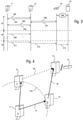
- FIG. 4 shows a schematic view of an installation of several pieces of hygiene equipment during communication according to an embodiment of the present invention.
- a first piece of hygiene equipment 11 is configured to emit a radio signal 31 comprising payload data into a range 310 where the signal 31 can be received essentially contemporaneously by the second piece of hygiene equipment 12 and third piece of hygiene equipment 13.
- both the second piece of hygiene equipment 12 and third piece of hygiene equipment 13 would be configured in the same way, a situation may need to be considered in which both pieces transmit the relayed payload data by radio signals 39 and 39' essentially at the same time.
- interference between signals 39 and 39' may occur which may render it impossible for the fourth piece of hygiene equipment 14 - or the access point 19 - to receive a signal in a proper way.
- Some embodiments of the present invention provide a configuration that allows two or more of pieces of hygiene equipment that all receive payload data to relay this data without interference and disruption and in a reliable way.
- the pieces of hygiene equipment consider varying delay values for delaying the transmission of relayed payload data.
- this may be implemented as follows:
- the second piece of hygiene equipment (e.g. dispenser) 12 is configured with a shorter delay as compared to the third dispenser 13.
- the dispenser 12 can emit the radio signal 39 toward the target without interference, since the third dispenser 13 is still waiting for its (longer) delay to elapse. After also this delay has elapsed, the dispenser 13 may also transmit the radio signal 39', which may be used for an increase of reliability by redundancy by the target 14 or 19, or may be simply ignored. In the latter case, any receiving entity (e.g. target or piece of hygiene equipment) may buffer a data message (payload data) for at least the time of a longest delay in the system, and compare any received data to data recently relayed and transmitted in order to decide whether a further transmission of relayed payload data may be suppressed.
- any receiving entity e.g. target or piece of hygiene equipment
- the piece of hygiene equipment 13 may monitor any further transmissions from other devices in response of receiving a signal with payload data to be relayed.
- the third piece of hygiene equipment 13 may also receive the radio signal 39 transmitted from the second piece of hygiene equipment 12 and thus may realize that data corresponding to the signal 31 has already been forwarded for relaying.
- the device 13, just as generally any piece of hygiene equipment according to this embodiment may decide on its own whether or not to transmit the data to be relayed.
- a delay value is dependent on an identifier of the individual piece of hygiene equipment.
- devices 12 and 13 have not conflicting (same or similar) delays, where they would transmit any data to be relayed at overlapping times which would - in turn - likely produce interference and render at least problematic the reception of the data by the target entity.
- devices manufactured with serial numbers in the vicinity/proximity or a given range may be ensured to all have default delays that differ from each other.
- devices 12 and 13 are installed at the same time, it can be ensured that no interference occurs.
- the pieces of hygiene equipment can be installed at the desired locations without the need for any manual or additional configuration effort.
- the devices are able to build a real self-organized "network" for relaying and forwarding data toward a given target. This can substantially facilitate the setup and mounting of pieces of hygiene equipment with the corresponding functionalities.
- the devices may be still equipped with switches or a communication interface that allows for manual reprogramming once the automatic procedures for relaying data fail or needs to be modified for other reasons.
- a piece of hygiene equipment has a processing circuit that is further arranged to add data to the data to be relayed before transmitting.
- the dispenser 12 may receive data from the dispenser 11 which is data to be relayed toward the device/dispenser 14.
- dispenser 12 adds data, for example in relation to its own filling state or its own measured observable, to the data to be relayed before transmitting any signals.
- the device/dispenser 14 receives data from both originators, namely dispenser 11 and 12 in this case, in one instance. This way forward can substantially contribute in saving power resources in the involved pieces of hygiene equipment, since the number of transmission instances can be reduced by "accumulating" data before the actual transmission.
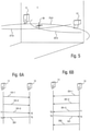
- FIG. 5 shows a schematic view of positioning with hygiene equipment according to an embodiment of the present invention.
- the hygiene equipment is shown in the context of a room 1 of the above discussed exemplary premises.
- room 1 is an intensive care ward room of a hospital.
- such a premise is provided with hygiene equipment and so is the ward room 1 as shown in Figure 5 .
- two pieces of hygiene equipment in the form of the liquid dispenser 11 and the tissue dispenser 12, which are, as such provided with the respective components and functionalities as described in conjunction with the corresponding embodiments of the present invention.
- the pieces 11 and 12 of hygiene equipment are in this exemplary configuration set up to transmit the respective radio signals 21-0 and 22-0.
- radio signals may be instead or additionally received by the pieces 11 and 12 of hygiene equipment.
- a third radio signal 23-0 is emitted into room 1 from equipment that is as such not shown.
- two or more radio signals are transmitted into room 1 in order to allow a determination of a position 30.
- the dimensionality and precision of position 30 may depend on the number of receivable signals and the corresponding properties of these signals.
- two or more signals originating from known sources may allow the determination of a 2D-position
- three or more signals originating from known sources may allow the determination of a 3D-position.
- it may be desired to have even more than three signals at hand which then not only contributes in an improved accuracy but may also compensate for shadowing or reflection phenomena.
- Figures 6A to 6D show schematic views of mechanisms for ranging by employing a time-of-flight determination of radio signals according to embodiments of the present invention.
- Figure 6A shows a schematic view of a general variant of so-called two way ranging (TWR) between pieces of hygiene equipment 11 and 12 (e.g. a dispenser), when, for example, the dispenser 11 acts as a beacon.
- TWR two way ranging
- the dispenser 11 transmits beacon signals 101-1, 101-2, in regular or irregular intervals.
- the device 12 can receive the beacon signal 101-3.
- the device 12 can obtain information on the timing when the signal 101-3 was received (T2) and obtain information on when a response signal 201 is transmitted (T3) toward the dispenser 11.
- the payload in the beacon signal 101 may contain information on identifying the dispenser 11, and this information may be encoded, together with relative or absolute information on the receiving/transmission timings, onto the payload of the response signal 201.
- the dispenser can thus obtain information on the timing when the signal 201 was received (T4) and obtain information on the timing when the signal 101-3 was transmitted (T1).
- the conveyed payload may also be employed to ensure that the signal 201 is in actual response to the beacon signal 101-3.
- further signals may be employed for any one of improving accuracy, employing cancelling techniques or adding redundancy.
- Figure 6B shows a schematic view of a similar ranging scheme where it is assumed that the device 12 transmits beacon signals 201-1, 201-2, in regular or irregular intervals.
- the ranging is carried out similar to the situation of Figure 6A , taking into account - at least indirectly - the timings T1 to T4.
- an additional signal 202 is employed, since the distance determination is made at the site of the device 11 and the necessary information on the timings should be available there.
- FIG. 6C shows a schematic view of time difference of arrival (TDOA) scheme between more than one piece of hygiene equipment.
- two pieces 11 and 12 of hygiene equipment transmit beacon signals 101-1,... and, respectively, 111-1,... into some overlapping range.
- the piece of hygiene equipment 13 is assumed to have received the two beacon signals 101-2 and 111-1.
- Both dispensers 11, 12 obtain information on timing when the signals 101-1 and 111-1 are transmitted by their respectively coupled antennae.
- the information on the timing can be identified as an instruction or synchronization signal employed for the plurality of dispensers 11, 12 to transmit the signals 101-1 and 111-1 at substantially the same time T1. In this way, the device 13 may determine different timings when the different signals are received.
- the signal 101-2 can be assumed to be received at T2 at device 13, and the signal 111-1 can be assumed to be received at T3 at device 13.
- the device 13 can initiate ranging calculations.
- further signals may be employed for any one of improving accuracy, employing cancelling techniques or adding redundancy.
- any determined distance or difference may be conveyed to some central entity (server) via another means of communication (e.g. a wireless network connection) or via an optional signal 203 to any one of the involved devices.
- FIG. 6D shows a schematic view of another time difference of arrival (TDOA) scheme.
- this scheme is similar to the one described in conjunction with Figure 6C , but here the piece of hygiene equipment 13 is the originator of the beacon signal. Therefore, the device 13 is assumed to transmit the beacon signals 204-1, 204-2,... at regular or irregular intervals. It may now be assumed that dispenser 11 receives the particular signal 204-2 at time T2, whereas dispenser 12 receives this particular signal 204-2 at time T3. Again, the payload carried by the signal 204 may be employed for facilitating identification and association of any received signals. The dispensers can obtain information on the receiving times T2 and T3 and can decode any payload to accomplish the mentioned association, so as to determine a time difference of arrival of one signal at different locations. This information may be fed back to the target device and/or a central entity (server) to complete a ranging and/or positioning calculation.
- server central entity
- the configuration shown in Figure 6D can be modified so that the device 13 is passive and 'listening' until device 11 or 12 sends a message to initiate the process (ranging).
- device 13 can transmit a 'single ping' that is received by devices 11, 12, where these devices are operated in synchronization and can calculate the desired information based on TDOA.
- devices 11 and 12 can be operated to be in synchronization and information on the timing T3 can be for example transported to device 11, when TDOA calculations are supposed to take place in device 11.
- the dispensers can then obtain information on the receiving times T2 and T3 and can decode any payload to accomplish the mentioned association.
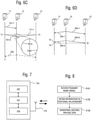
- Figure 7 shows a schematic view of device functionalities for implementing embodiments of the present invention.
- a piece of hygiene equipment 124 has a processing circuit 121, a memory 122, a radio circuit 123, and an antenna 124.
- the radio circuit 123 is configured to receive and transmit a radio signal carrying payload data using the antenna 124.
- the memory 122 stores code to configure the processing circuit 121 to obtain information on a positional relationship to another device by instructing the radio circuit to receive and/or transmit a radio signal carrying first payload data, and to generate second payload data on the basis of the obtained information on the obtained positional relationship, and to instruct the radio circuit to transmit a radio signal carrying said second payload data.
- Figure 8 shows a flowchart of a general method embodiment of the present invention.
- the method is for operating a piece of hygiene equipment that has a processing circuit, a memory, and a radio circuit.
- the method comprises a step S101 of receiving and transmitting a radio signal carrying payload data, a step S102 of obtaining information on a positional relationship to another device by instructing the radio circuit to receive and/or transmit a radio signal carrying first payload data, and a step S103 of generating second payload data on the basis of the obtained information on the obtained positional relationship, and to instruct the radio circuit to transmit a radio signal carrying said second payload data.
Landscapes
- Engineering & Computer Science (AREA)
- Radar, Positioning & Navigation (AREA)
- Remote Sensing (AREA)
- Physics & Mathematics (AREA)
- General Physics & Mathematics (AREA)
- Computer Networks & Wireless Communication (AREA)
- Health & Medical Sciences (AREA)
- Public Health (AREA)
- Telephonic Communication Services (AREA)
- Mobile Radio Communication Systems (AREA)
- Selective Calling Equipment (AREA)
Claims (14)
- Hygieneausrüstungsteil ((11, 124), umfassend eine Verarbeitungsschaltung (111, 121) und eine Funkschaltung (112, 123),wobei die Funkschaltung (112, 123) konfiguriert ist, um ein Funksignal (20), das Nutzlastdaten (211, ...) trägt, zu empfangen und zu senden,wobei die Verarbeitungsschaltung (111, 121) konfiguriert ist, um Informationen über eine Positionsbeziehung zu einer anderen Vorrichtung (12, 13, ...) durch Anweisen der Funkschaltung (112, 123), ein Funksignal (20), das erste Nutzlastdaten (211, ...) trägt, zu empfangen und zu senden, zu erhalten,wobei die Verarbeitungsschaltung (111, 121) konfiguriert ist, um zweite Nutzlastdaten auf der Grundlage der erhaltenen Informationen über die erhaltene Positionsbeziehung zu erzeugen, und die Funkschaltung (112, 123) anzuweisen, ein Funksignal (20), das die zweiten Nutzlastdaten trägt, zu senden,wobei die Verarbeitungsschaltung konfiguriert ist, um ein ausgehendes Funksignal (20), das spezifische Sendungsnutzlastdaten trägt, zu senden, und/oder ein eingehendes Funksignal (20), das spezifische Empfangsnutzlastdaten trägt, zu empfangen, um einen Kommunikationspartner zu bestimmen, an den ausgehende Funksignale (20) zu senden sind, und von dem eingehende Funksignale (20) zu empfangen sind, undwobei das Hygieneausrüstungsteil (11, 124) weiter konfiguriert ist, um einen Verbrauchsstoff an einen Nutzer abzugeben, oder einen Verbrauchsstoff von einem Nutzer zu entsorgen, und weiter einen Sensorabschnitt umfasst, konfiguriert, um einen Wert, der sich auf einen Behälter des Verbrauchsstoffs bezieht, zu bestimmen, wobei die Verarbeitungsschaltung angeordnet ist, um die Nutzlastdaten (211, ...) in Bezug auf den bestimmten Wert zusammenzutragen.
- Hygieneausrüstungsteil (11, 124) nach Anspruch 1, wobei die Verarbeitungsschaltung (111, 121) konfiguriert ist, um die ersten Nutzlastdaten, die von einem empfangenen Funksignal (20) getragen werden, zu erhalten, und eine Positionsbeziehung zu einem Urheber des empfangenen Funksignals (20) zu bestimmen; und
wobei die Verarbeitungsschaltung (111, 121) konfiguriert ist, um die zweiten Nutzlastdaten zu erzeugen, um Informationen über die bestimmte Positionsbeziehung mit einem oder mehreren Urhebern zu teilen. - Hygieneausrüstungsteil (11, 124) nach Anspruch 1 oder 2, wobei die Verarbeitungsschaltung (111, 121) konfiguriert ist, um den Kommunikationspartner zu bestimmen und Informationen über den bestimmten Kommunikationspartner in einem Speicherabschnitt zu speichern.
- Hygieneausrüstungsteil (11, 124) nach einem der Ansprüche 1 bis 3, wobei die Verarbeitungsschaltung (111, 121) konfiguriert ist, um in einem ersten Modus und in einem zweiten Modus betrieben zu werden, wobei die Verarbeitungsschaltung (111, 121) während des ersten Modus konfiguriert ist, um den Kommunikationspartner zu bestimmen, und wobei die Verarbeitungsschaltung (111, 121) während des zweiten Modus konfiguriert ist, um die Informationen über eine Positionsbeziehung zu dem Kommunikationspartner als die andere Vorrichtung zu erhalten.
- Hygieneausrüstungsteil (11, 124) nach Anspruch 4, wobei die Verarbeitungsschaltung (111, 121) konfiguriert ist, um die zweiten Nutzlastdaten auf der Grundlage der erhaltenen Informationen über die Positionsbeziehung zu dem Kommunikationspartner zu erzeugen.
- Hygieneausrüstungsteil (11, 124) nach Anspruch 4 oder 5, wobei der erste und zweite Modus nach dem Einschalten des Hygieneausrüstungsteils (11, 124) für eine vorbestimmte Zeit aktiviert werden.
- Hygieneausrüstungsteil (11, 124) nach einem der Ansprüche 1 bis 6, wobei das Hygieneausrüstungsteil (11, 124) weiter eine Quelle elektrischen Stroms, vorzugsweise eine Batterie, umfasst.
- Hygieneausrüstungsteil (11, 124) nach Anspruch 7, wobei eine Isolierschleife eine elektrische Verbindung mit der Quelle elektrischen Stroms unterbindet und das Hygieneausrüstungsteil (11, 124) durch Entfernen der Schleife eingeschaltet wird.
- Hygieneausrüstungsteil (11, 124) nach einem der Ansprüche 1 bis 8, wobei die Verarbeitungsschaltung (111, 121) weiter angeordnet ist, um das Senden der ersten und/oder zweiten Nutzlastdaten entsprechend einem vorbestimmten Wert zu verzögern.
- Hygieneausrüstungsteil (11, 124) nach Anspruch 9, wobei der vorbestimmte Wert für das Hygieneausrüstungsteil (11, 124) spezifisch ist.
- Hygieneausrüstungsteil (11, 124) nach Anspruch 10, wobei dem Hygieneausrüstungsteil (11, 124) eine Kennung zugewiesen ist, und wobei der vorbestimmte Wert in Bezug auf die Kennung eingestellt wird.
- Hygieneausrüstungsteil (11, 124) nach einem der Ansprüche 1 bis 11, umfassend einen beliebigen von einem Seifenspender, Handtuchspender, Desinfektionsmittelspender, Alcogelspender, Papiertuchspender, Hygieneartikelspender, Abfalleimer, Eimer für gebrauchte Handtücher, und einen Toilettenpapierspender.
- System, umfassend eine Vielzahl von Hygieneausrüstungsteilen (11, 124) nach einem der Ansprüche 1 bis 12.
- Verfahren zum Betreiben eines Hygieneausrüstungsteils (11, 124), umfassend eine Verarbeitungsschaltung (111, 121) und eine Funkschaltung (112, 123), wobei das Verfahren die Schritte umfasst:Empfangen und Senden eines Funksignals (20), das Nutzlastdaten (211, ...) trägt, mit der Funkschaltung (112, 123),Erhalten von Informationen über eine Positionsbeziehung zu einer anderen Vorrichtung (12, 13, ...) durch Anweisen der Funkschaltung (112, 123), ein Funksignal (20), das erste Nutzlastdaten trägt, zu empfangen und/oder zu senden,Erzeugen zweiter Nutzlastdaten auf der Grundlage der erhaltenen Informationen über die erhaltene Positionsbeziehung, und um die Funkschaltung (112, 123) anzuweisen, ein Funksignal (20), das die zweiten Nutzlastdaten trägt, zu senden,Senden eines ausgehenden Funksignals (20), das spezifische Sendungsnutzlastdaten trägt, und/oder Empfangen eines eingehenden Funksignals (20), das spezifische Empfangsnutzlastdaten trägt, zum Bestimmen eines Kommunikationspartners, an den ausgehende Funksignale (20) zu senden sind, und von dem eingehende Funksignale (20) zu empfangen sind,Abgeben eines Verbrauchsstoffs an einen Nutzer, oder Entsorgen eines Verbrauchsstoffs von einem Nutzer,Bestimmen, mit einem Sensorabschnitt des Hygieneausrüstungsteils (11, 124), eines Werts, der sich auf einen Behälter des Verbrauchsstoffs bezieht, und einen Schritt desZusammentragens der Nutzlastdaten (211, ...) in Bezug auf den bestimmten Wert.
Priority Applications (1)
| Application Number | Priority Date | Filing Date | Title |
|---|---|---|---|
| EP22152914.2A EP4009067B1 (de) | 2016-12-07 | 2016-12-07 | Automatisches aufstellen von hygieneausrüstung |
Applications Claiming Priority (1)
| Application Number | Priority Date | Filing Date | Title |
|---|---|---|---|
| PCT/EP2016/080144 WO2018103847A1 (en) | 2016-12-07 | 2016-12-07 | Automatic setting-up of hygiene equipment |
Related Child Applications (2)
| Application Number | Title | Priority Date | Filing Date |
|---|---|---|---|
| EP22152914.2A Division EP4009067B1 (de) | 2016-12-07 | 2016-12-07 | Automatisches aufstellen von hygieneausrüstung |
| EP22152914.2A Division-Into EP4009067B1 (de) | 2016-12-07 | 2016-12-07 | Automatisches aufstellen von hygieneausrüstung |
Publications (2)
| Publication Number | Publication Date |
|---|---|
| EP3552038A1 EP3552038A1 (de) | 2019-10-16 |
| EP3552038B1 true EP3552038B1 (de) | 2022-03-02 |
Family
ID=57539242
Family Applications (2)
| Application Number | Title | Priority Date | Filing Date |
|---|---|---|---|
| EP16809361.5A Active EP3552038B1 (de) | 2016-12-07 | 2016-12-07 | Automatisches aufstellen von hygieneausrüstung |
| EP22152914.2A Active EP4009067B1 (de) | 2016-12-07 | 2016-12-07 | Automatisches aufstellen von hygieneausrüstung |
Family Applications After (1)
| Application Number | Title | Priority Date | Filing Date |
|---|---|---|---|
| EP22152914.2A Active EP4009067B1 (de) | 2016-12-07 | 2016-12-07 | Automatisches aufstellen von hygieneausrüstung |
Country Status (4)
| Country | Link |
|---|---|
| US (1) | US11402490B2 (de) |
| EP (2) | EP3552038B1 (de) |
| TW (1) | TW201824011A (de) |
| WO (1) | WO2018103847A1 (de) |
Families Citing this family (4)
| Publication number | Priority date | Publication date | Assignee | Title |
|---|---|---|---|---|
| US11403888B2 (en) * | 2018-09-24 | 2022-08-02 | Gojo Industries, Inc. | Method and system for using data packet beaconing to determine compliance with protocols |
| US11871322B2 (en) | 2018-12-21 | 2024-01-09 | Essity Hygiene And Health Aktiebolag | Installation of hygiene equipment |
| WO2021021611A1 (en) * | 2019-07-26 | 2021-02-04 | Gojo Industries, Inc. | Systems and methods for increased accuracy for tracking hygiene compliance |
| US20240008693A1 (en) * | 2020-08-28 | 2024-01-11 | Tekt Industries Pty Ltd | System for Monitoring Usage of Sanitary Product |
Citations (1)
| Publication number | Priority date | Publication date | Assignee | Title |
|---|---|---|---|---|
| AU2014227493A1 (en) * | 2013-09-23 | 2015-04-09 | Kcrown Australia Pty Ltd | Washroom monitoring and consumable supply management system |
Family Cites Families (39)
| Publication number | Priority date | Publication date | Assignee | Title |
|---|---|---|---|---|
| US4412292A (en) * | 1981-02-17 | 1983-10-25 | The Coca-Cola Company | System for the remote monitoring of vending machines |
| GB9725168D0 (en) * | 1997-11-27 | 1998-01-28 | Design To Distribution Limited | Security system |
| JPH11185120A (ja) * | 1997-12-19 | 1999-07-09 | Sanyo Electric Co Ltd | ネットワークに接続するための自動販売機及び自動販売機ネットワークシステム |
| US7084737B1 (en) * | 1999-08-20 | 2006-08-01 | Motorola, Inc. | Method and apparatus for locating a nearby alternate vending machine for a desired product |
| US6727818B1 (en) | 1999-10-29 | 2004-04-27 | Hill-Rom Services, Inc. | Hygiene monitoring system |
| US20050091552A1 (en) * | 2003-04-11 | 2005-04-28 | Piccionelli Gregory A. | Secure portable computer and security method |
| US7242306B2 (en) | 2001-05-08 | 2007-07-10 | Hill-Rom Services, Inc. | Article locating and tracking apparatus and method |
| KR20030089626A (ko) * | 2002-05-16 | 2003-11-22 | 여태순 | 자동판매기 관리 시스템 |
| US7194283B2 (en) | 2002-08-14 | 2007-03-20 | Intel Corporation | Method and apparatus for communication using multiple communication protocols |
| CN102665265B (zh) | 2003-09-26 | 2016-12-14 | 美商内数位科技公司 | 用于3gpp时分双工通信系统的rnc和接收站及其执行方法 |
| US7783380B2 (en) | 2003-12-31 | 2010-08-24 | Kimberly-Clark Worldwide, Inc. | System and method for measuring, monitoring and controlling washroom dispensers and products |
| DE102004060930B4 (de) * | 2004-12-17 | 2014-09-18 | Siemens Aktiengesellschaft | Sicherung eines medizinischen Geräts |
| US8191779B2 (en) * | 2005-10-27 | 2012-06-05 | Avt, Inc. | Wireless management of remote vending machines |
| US7899396B2 (en) | 2006-06-02 | 2011-03-01 | Qulacomm Incorporated | Efficient operation for co-located WLAN and Bluetooth |
| KR100842522B1 (ko) | 2006-11-27 | 2008-07-01 | 삼성전자주식회사 | 방송 서비스와 이동통신 서비스를 지원하는 복합단말기에서 간섭 제거 방법 및 장치와 그 단말기 |
| US8189710B2 (en) | 2007-04-06 | 2012-05-29 | Intel Corporation | Architecture and methods for coexistence of wireless radios having differing protocols |
| US8750796B2 (en) | 2007-05-17 | 2014-06-10 | Abbott Medical Optics Inc. | Exclusive pairing technique for short-range communication devices |
| US9686049B2 (en) | 2007-09-12 | 2017-06-20 | Avago Technologies General Ip (Singapore) Pte. Ltd | Method and system for Bluetooth (BT) delayed acknowledgement (ACK) |
| US8135344B2 (en) | 2008-02-13 | 2012-03-13 | Apple Inc. | Method for using bluetooth module to process non-bluetooth signals |
| US20100051637A1 (en) | 2008-09-03 | 2010-03-04 | Hsiu-Hung Shu | Wireless parallel dispensing system |
| US8279063B2 (en) | 2008-11-12 | 2012-10-02 | Xhale, Inc. | Personnel location and monitoring system and method for enclosed facilities |
| US8201707B2 (en) | 2009-02-27 | 2012-06-19 | Gotohti.Com Inc | Manual fluid dispenser with discharge measurement |
| US8823494B1 (en) | 2010-11-19 | 2014-09-02 | Logitech Europe S.A. | Systems and methods for wireless device connection and pairing |
| US20120245729A1 (en) * | 2011-03-24 | 2012-09-27 | Gojo Industries, Inc. | Network enabled dispenser |
| US8565112B2 (en) | 2011-04-26 | 2013-10-22 | Qualcomm Incorporated | Concurrent transmission of Wi-Fi and Bluetooth signals |
| WO2013063690A1 (en) | 2011-11-04 | 2013-05-10 | Gotohti.Com Inc. | Dispenser and contaminant sensor |
| US8725080B2 (en) | 2011-12-29 | 2014-05-13 | Motorola Solutions, Inc. | Method and apparatus for transmission in a trunked radio communication system |
| CA2862506C (en) | 2012-02-08 | 2020-04-28 | Simplehuman, Llc | Liquid dispensing units |
| US20140022941A1 (en) | 2012-07-17 | 2014-01-23 | The Procter & Gamble Company | Systems and methods for networking consumer devices |
| UA114637C2 (uk) | 2012-08-31 | 2017-07-10 | Ска Хайджин Продактс Аб | Система і спосіб для збирання і моніторингу даних певного простору |
| ES2625693T3 (es) | 2012-10-30 | 2017-07-20 | Nokia Technologies Oy | Uso de energía baja de Bluetooth |
| US20140179231A1 (en) * | 2012-12-26 | 2014-06-26 | Cellco Partnership D/B/A Verizon Wireless | Smart vending machine |
| US20150199883A1 (en) | 2014-01-15 | 2015-07-16 | Kaylin Wayne Hartley | Hand Sanitation Dispensing and Tracking Systems and Methods |
| US9913562B2 (en) | 2014-02-11 | 2018-03-13 | Gojo Industries, Inc. | Dispensing system with material level detector |
| US9886810B1 (en) | 2014-04-09 | 2018-02-06 | Gpcp Ip Holdings Llc | Universal dispenser interface |
| US9645561B2 (en) | 2015-01-23 | 2017-05-09 | Georgia-Pacific Consumer Products Lp | Optimizing a dispensing parameter of a product dispenser based on product usage data |
| WO2016168082A1 (en) | 2015-04-13 | 2016-10-20 | Pi Konrad David | Method and system for hand washing compliance |
| CA2911934A1 (en) | 2015-11-13 | 2017-05-13 | Heiner Ophardt | Lever operated fluid dispenser with rotary potentiometer |
| GB201520277D0 (en) | 2015-11-17 | 2015-12-30 | Kennedy Hygiene Products Ltd | Dispensing apparatus and method |
-
2016
- 2016-12-07 EP EP16809361.5A patent/EP3552038B1/de active Active
- 2016-12-07 EP EP22152914.2A patent/EP4009067B1/de active Active
- 2016-12-07 US US16/467,521 patent/US11402490B2/en active Active
- 2016-12-07 WO PCT/EP2016/080144 patent/WO2018103847A1/en not_active Ceased
-
2017
- 2017-12-07 TW TW106143007A patent/TW201824011A/zh unknown
Patent Citations (1)
| Publication number | Priority date | Publication date | Assignee | Title |
|---|---|---|---|---|
| AU2014227493A1 (en) * | 2013-09-23 | 2015-04-09 | Kcrown Australia Pty Ltd | Washroom monitoring and consumable supply management system |
Also Published As
| Publication number | Publication date |
|---|---|
| US11402490B2 (en) | 2022-08-02 |
| TW201824011A (zh) | 2018-07-01 |
| EP4009067B1 (de) | 2024-09-11 |
| EP3552038A1 (de) | 2019-10-16 |
| US20190331786A1 (en) | 2019-10-31 |
| EP4009067A1 (de) | 2022-06-08 |
| WO2018103847A1 (en) | 2018-06-14 |
Similar Documents
| Publication | Publication Date | Title |
|---|---|---|
| US11729595B2 (en) | Apparatuses and method for transmitting payload data between hygiene equipments with radio transmission capabilities | |
| US10715465B1 (en) | Asset tracking systems and methods | |
| EP3552038B1 (de) | Automatisches aufstellen von hygieneausrüstung | |
| JP6749419B2 (ja) | ポジショニングシステム | |
| CA2882066C (en) | A system and a method for data collection and monitoring of a defined space | |
| JP6816021B2 (ja) | 位置特定システム | |
| US20130300541A1 (en) | Improving positioning accuracy of location tracking system | |
| JP2007514134A (ja) | 位置特定システム | |
| US20160292972A1 (en) | Systems and methods for locating a public facility | |
| JP2014517651A (ja) | 無線通信システム | |
| WO2018196979A1 (en) | Improved hygiene compliance monitoring | |
| JP5962349B2 (ja) | 無線通信システム、無線通信方法、及び無線通信装置 | |
| US10132917B2 (en) | Systems and methods of location and tracking | |
| JP2006266859A (ja) | 位置測定システムおよび位置測定方法 | |
| US20230199349A1 (en) | Data collection and monitoring for hygiene equipment | |
| US11282371B2 (en) | Installation of hygiene equipment | |
| EP2908611A1 (de) | Vorrichtung zur lokalisierung und identifizierung von objekten in einem raum und ermöglichung des zugangs zu einem kontextuellen dienst | |
| WO2018103845A1 (en) | Hygiene equipment system for positioning | |
| EP2976992B1 (de) | Pflegerufsystem mit lokalem betriebsmodus | |
| EP2978164B1 (de) | Hybrides Pflegerufsystem |
Legal Events
| Date | Code | Title | Description |
|---|---|---|---|
| STAA | Information on the status of an ep patent application or granted ep patent |
Free format text: STATUS: UNKNOWN |
|
| STAA | Information on the status of an ep patent application or granted ep patent |
Free format text: STATUS: THE INTERNATIONAL PUBLICATION HAS BEEN MADE |
|
| PUAI | Public reference made under article 153(3) epc to a published international application that has entered the european phase |
Free format text: ORIGINAL CODE: 0009012 |
|
| STAA | Information on the status of an ep patent application or granted ep patent |
Free format text: STATUS: REQUEST FOR EXAMINATION WAS MADE |
|
| 17P | Request for examination filed |
Effective date: 20190625 |
|
| AK | Designated contracting states |
Kind code of ref document: A1 Designated state(s): AL AT BE BG CH CY CZ DE DK EE ES FI FR GB GR HR HU IE IS IT LI LT LU LV MC MK MT NL NO PL PT RO RS SE SI SK SM TR |
|
| AX | Request for extension of the european patent |
Extension state: BA ME |
|
| DAV | Request for validation of the european patent (deleted) | ||
| DAX | Request for extension of the european patent (deleted) | ||
| STAA | Information on the status of an ep patent application or granted ep patent |
Free format text: STATUS: EXAMINATION IS IN PROGRESS |
|
| 17Q | First examination report despatched |
Effective date: 20200930 |
|
| GRAP | Despatch of communication of intention to grant a patent |
Free format text: ORIGINAL CODE: EPIDOSNIGR1 |
|
| STAA | Information on the status of an ep patent application or granted ep patent |
Free format text: STATUS: GRANT OF PATENT IS INTENDED |
|
| INTG | Intention to grant announced |
Effective date: 20210914 |
|
| GRAS | Grant fee paid |
Free format text: ORIGINAL CODE: EPIDOSNIGR3 |
|
| GRAA | (expected) grant |
Free format text: ORIGINAL CODE: 0009210 |
|
| STAA | Information on the status of an ep patent application or granted ep patent |
Free format text: STATUS: THE PATENT HAS BEEN GRANTED |
|
| AK | Designated contracting states |
Kind code of ref document: B1 Designated state(s): AL AT BE BG CH CY CZ DE DK EE ES FI FR GB GR HR HU IE IS IT LI LT LU LV MC MK MT NL NO PL PT RO RS SE SI SK SM TR |
|
| REG | Reference to a national code |
Ref country code: GB Ref legal event code: FG4D |
|
| REG | Reference to a national code |
Ref country code: CH Ref legal event code: EP Ref country code: AT Ref legal event code: REF Ref document number: 1472702 Country of ref document: AT Kind code of ref document: T Effective date: 20220315 |
|
| REG | Reference to a national code |
Ref country code: DE Ref legal event code: R096 Ref document number: 602016069656 Country of ref document: DE |
|
| REG | Reference to a national code |
Ref country code: IE Ref legal event code: FG4D |
|
| REG | Reference to a national code |
Ref country code: LT Ref legal event code: MG9D |
|
| REG | Reference to a national code |
Ref country code: NL Ref legal event code: MP Effective date: 20220302 |
|
| PG25 | Lapsed in a contracting state [announced via postgrant information from national office to epo] |
Ref country code: SE Free format text: LAPSE BECAUSE OF FAILURE TO SUBMIT A TRANSLATION OF THE DESCRIPTION OR TO PAY THE FEE WITHIN THE PRESCRIBED TIME-LIMIT Effective date: 20220302 Ref country code: RS Free format text: LAPSE BECAUSE OF FAILURE TO SUBMIT A TRANSLATION OF THE DESCRIPTION OR TO PAY THE FEE WITHIN THE PRESCRIBED TIME-LIMIT Effective date: 20220302 Ref country code: NO Free format text: LAPSE BECAUSE OF FAILURE TO SUBMIT A TRANSLATION OF THE DESCRIPTION OR TO PAY THE FEE WITHIN THE PRESCRIBED TIME-LIMIT Effective date: 20220602 Ref country code: LT Free format text: LAPSE BECAUSE OF FAILURE TO SUBMIT A TRANSLATION OF THE DESCRIPTION OR TO PAY THE FEE WITHIN THE PRESCRIBED TIME-LIMIT Effective date: 20220302 Ref country code: HR Free format text: LAPSE BECAUSE OF FAILURE TO SUBMIT A TRANSLATION OF THE DESCRIPTION OR TO PAY THE FEE WITHIN THE PRESCRIBED TIME-LIMIT Effective date: 20220302 Ref country code: ES Free format text: LAPSE BECAUSE OF FAILURE TO SUBMIT A TRANSLATION OF THE DESCRIPTION OR TO PAY THE FEE WITHIN THE PRESCRIBED TIME-LIMIT Effective date: 20220302 Ref country code: BG Free format text: LAPSE BECAUSE OF FAILURE TO SUBMIT A TRANSLATION OF THE DESCRIPTION OR TO PAY THE FEE WITHIN THE PRESCRIBED TIME-LIMIT Effective date: 20220602 |
|
| REG | Reference to a national code |
Ref country code: AT Ref legal event code: MK05 Ref document number: 1472702 Country of ref document: AT Kind code of ref document: T Effective date: 20220302 |
|
| PG25 | Lapsed in a contracting state [announced via postgrant information from national office to epo] |
Ref country code: PL Free format text: LAPSE BECAUSE OF FAILURE TO SUBMIT A TRANSLATION OF THE DESCRIPTION OR TO PAY THE FEE WITHIN THE PRESCRIBED TIME-LIMIT Effective date: 20220302 Ref country code: LV Free format text: LAPSE BECAUSE OF FAILURE TO SUBMIT A TRANSLATION OF THE DESCRIPTION OR TO PAY THE FEE WITHIN THE PRESCRIBED TIME-LIMIT Effective date: 20220302 Ref country code: GR Free format text: LAPSE BECAUSE OF FAILURE TO SUBMIT A TRANSLATION OF THE DESCRIPTION OR TO PAY THE FEE WITHIN THE PRESCRIBED TIME-LIMIT Effective date: 20220603 Ref country code: FI Free format text: LAPSE BECAUSE OF FAILURE TO SUBMIT A TRANSLATION OF THE DESCRIPTION OR TO PAY THE FEE WITHIN THE PRESCRIBED TIME-LIMIT Effective date: 20220302 |
|
| PG25 | Lapsed in a contracting state [announced via postgrant information from national office to epo] |
Ref country code: NL Free format text: LAPSE BECAUSE OF FAILURE TO SUBMIT A TRANSLATION OF THE DESCRIPTION OR TO PAY THE FEE WITHIN THE PRESCRIBED TIME-LIMIT Effective date: 20220302 |
|
| PG25 | Lapsed in a contracting state [announced via postgrant information from national office to epo] |
Ref country code: SM Free format text: LAPSE BECAUSE OF FAILURE TO SUBMIT A TRANSLATION OF THE DESCRIPTION OR TO PAY THE FEE WITHIN THE PRESCRIBED TIME-LIMIT Effective date: 20220302 Ref country code: SK Free format text: LAPSE BECAUSE OF FAILURE TO SUBMIT A TRANSLATION OF THE DESCRIPTION OR TO PAY THE FEE WITHIN THE PRESCRIBED TIME-LIMIT Effective date: 20220302 Ref country code: RO Free format text: LAPSE BECAUSE OF FAILURE TO SUBMIT A TRANSLATION OF THE DESCRIPTION OR TO PAY THE FEE WITHIN THE PRESCRIBED TIME-LIMIT Effective date: 20220302 Ref country code: PT Free format text: LAPSE BECAUSE OF FAILURE TO SUBMIT A TRANSLATION OF THE DESCRIPTION OR TO PAY THE FEE WITHIN THE PRESCRIBED TIME-LIMIT Effective date: 20220704 Ref country code: EE Free format text: LAPSE BECAUSE OF FAILURE TO SUBMIT A TRANSLATION OF THE DESCRIPTION OR TO PAY THE FEE WITHIN THE PRESCRIBED TIME-LIMIT Effective date: 20220302 Ref country code: CZ Free format text: LAPSE BECAUSE OF FAILURE TO SUBMIT A TRANSLATION OF THE DESCRIPTION OR TO PAY THE FEE WITHIN THE PRESCRIBED TIME-LIMIT Effective date: 20220302 Ref country code: AT Free format text: LAPSE BECAUSE OF FAILURE TO SUBMIT A TRANSLATION OF THE DESCRIPTION OR TO PAY THE FEE WITHIN THE PRESCRIBED TIME-LIMIT Effective date: 20220302 |
|
| PG25 | Lapsed in a contracting state [announced via postgrant information from national office to epo] |
Ref country code: IS Free format text: LAPSE BECAUSE OF FAILURE TO SUBMIT A TRANSLATION OF THE DESCRIPTION OR TO PAY THE FEE WITHIN THE PRESCRIBED TIME-LIMIT Effective date: 20220702 Ref country code: AL Free format text: LAPSE BECAUSE OF FAILURE TO SUBMIT A TRANSLATION OF THE DESCRIPTION OR TO PAY THE FEE WITHIN THE PRESCRIBED TIME-LIMIT Effective date: 20220302 |
|
| REG | Reference to a national code |
Ref country code: DE Ref legal event code: R097 Ref document number: 602016069656 Country of ref document: DE |
|
| PLBE | No opposition filed within time limit |
Free format text: ORIGINAL CODE: 0009261 |
|
| STAA | Information on the status of an ep patent application or granted ep patent |
Free format text: STATUS: NO OPPOSITION FILED WITHIN TIME LIMIT |
|
| PG25 | Lapsed in a contracting state [announced via postgrant information from national office to epo] |
Ref country code: DK Free format text: LAPSE BECAUSE OF FAILURE TO SUBMIT A TRANSLATION OF THE DESCRIPTION OR TO PAY THE FEE WITHIN THE PRESCRIBED TIME-LIMIT Effective date: 20220302 |
|
| 26N | No opposition filed |
Effective date: 20221205 |
|
| PG25 | Lapsed in a contracting state [announced via postgrant information from national office to epo] |
Ref country code: SI Free format text: LAPSE BECAUSE OF FAILURE TO SUBMIT A TRANSLATION OF THE DESCRIPTION OR TO PAY THE FEE WITHIN THE PRESCRIBED TIME-LIMIT Effective date: 20220302 |
|
| PG25 | Lapsed in a contracting state [announced via postgrant information from national office to epo] |
Ref country code: IT Free format text: LAPSE BECAUSE OF FAILURE TO SUBMIT A TRANSLATION OF THE DESCRIPTION OR TO PAY THE FEE WITHIN THE PRESCRIBED TIME-LIMIT Effective date: 20220302 |
|
| REG | Reference to a national code |
Ref country code: CH Ref legal event code: PL |
|
| REG | Reference to a national code |
Ref country code: BE Ref legal event code: MM Effective date: 20221231 |
|
| PG25 | Lapsed in a contracting state [announced via postgrant information from national office to epo] |
Ref country code: LU Free format text: LAPSE BECAUSE OF NON-PAYMENT OF DUE FEES Effective date: 20221207 |
|
| PG25 | Lapsed in a contracting state [announced via postgrant information from national office to epo] |
Ref country code: LI Free format text: LAPSE BECAUSE OF NON-PAYMENT OF DUE FEES Effective date: 20221231 Ref country code: IE Free format text: LAPSE BECAUSE OF NON-PAYMENT OF DUE FEES Effective date: 20221207 Ref country code: CH Free format text: LAPSE BECAUSE OF NON-PAYMENT OF DUE FEES Effective date: 20221231 |
|
| PG25 | Lapsed in a contracting state [announced via postgrant information from national office to epo] |
Ref country code: BE Free format text: LAPSE BECAUSE OF NON-PAYMENT OF DUE FEES Effective date: 20221231 |
|
| PG25 | Lapsed in a contracting state [announced via postgrant information from national office to epo] |
Ref country code: HU Free format text: LAPSE BECAUSE OF FAILURE TO SUBMIT A TRANSLATION OF THE DESCRIPTION OR TO PAY THE FEE WITHIN THE PRESCRIBED TIME-LIMIT; INVALID AB INITIO Effective date: 20161207 |
|
| PG25 | Lapsed in a contracting state [announced via postgrant information from national office to epo] |
Ref country code: CY Free format text: LAPSE BECAUSE OF FAILURE TO SUBMIT A TRANSLATION OF THE DESCRIPTION OR TO PAY THE FEE WITHIN THE PRESCRIBED TIME-LIMIT Effective date: 20220302 |
|
| PG25 | Lapsed in a contracting state [announced via postgrant information from national office to epo] |
Ref country code: MK Free format text: LAPSE BECAUSE OF FAILURE TO SUBMIT A TRANSLATION OF THE DESCRIPTION OR TO PAY THE FEE WITHIN THE PRESCRIBED TIME-LIMIT Effective date: 20220302 |
|
| PG25 | Lapsed in a contracting state [announced via postgrant information from national office to epo] |
Ref country code: MC Free format text: LAPSE BECAUSE OF FAILURE TO SUBMIT A TRANSLATION OF THE DESCRIPTION OR TO PAY THE FEE WITHIN THE PRESCRIBED TIME-LIMIT Effective date: 20220302 |
|
| PG25 | Lapsed in a contracting state [announced via postgrant information from national office to epo] |
Ref country code: TR Free format text: LAPSE BECAUSE OF FAILURE TO SUBMIT A TRANSLATION OF THE DESCRIPTION OR TO PAY THE FEE WITHIN THE PRESCRIBED TIME-LIMIT Effective date: 20220302 Ref country code: MC Free format text: LAPSE BECAUSE OF FAILURE TO SUBMIT A TRANSLATION OF THE DESCRIPTION OR TO PAY THE FEE WITHIN THE PRESCRIBED TIME-LIMIT Effective date: 20220302 |
|
| PG25 | Lapsed in a contracting state [announced via postgrant information from national office to epo] |
Ref country code: MT Free format text: LAPSE BECAUSE OF FAILURE TO SUBMIT A TRANSLATION OF THE DESCRIPTION OR TO PAY THE FEE WITHIN THE PRESCRIBED TIME-LIMIT Effective date: 20220302 |
|
| PGFP | Annual fee paid to national office [announced via postgrant information from national office to epo] |
Ref country code: GB Payment date: 20241217 Year of fee payment: 9 |
|
| PGFP | Annual fee paid to national office [announced via postgrant information from national office to epo] |
Ref country code: FR Payment date: 20241227 Year of fee payment: 9 |
|
| PGFP | Annual fee paid to national office [announced via postgrant information from national office to epo] |
Ref country code: DE Payment date: 20241227 Year of fee payment: 9 |