EP3552032B1 - System zur erkennung von defekten in einer übertragungsleitung unter verwendung eines komplexen signals - Google Patents
System zur erkennung von defekten in einer übertragungsleitung unter verwendung eines komplexen signals Download PDFInfo
- Publication number
- EP3552032B1 EP3552032B1 EP17804207.3A EP17804207A EP3552032B1 EP 3552032 B1 EP3552032 B1 EP 3552032B1 EP 17804207 A EP17804207 A EP 17804207A EP 3552032 B1 EP3552032 B1 EP 3552032B1
- Authority
- EP
- European Patent Office
- Prior art keywords
- signal
- complex
- frequency
- reflectogram
- domain
- Prior art date
- Legal status (The legal status is an assumption and is not a legal conclusion. Google has not performed a legal analysis and makes no representation as to the accuracy of the status listed.)
- Active
Links
Images


Classifications
-
- G—PHYSICS
- G01—MEASURING; TESTING
- G01R—MEASURING ELECTRIC VARIABLES; MEASURING MAGNETIC VARIABLES
- G01R31/00—Arrangements for testing electric properties; Arrangements for locating electric faults; Arrangements for electrical testing characterised by what is being tested not provided for elsewhere
- G01R31/08—Locating faults in cables, transmission lines, or networks
- G01R31/11—Locating faults in cables, transmission lines, or networks using pulse reflection methods
-
- G—PHYSICS
- G01—MEASURING; TESTING
- G01R—MEASURING ELECTRIC VARIABLES; MEASURING MAGNETIC VARIABLES
- G01R31/00—Arrangements for testing electric properties; Arrangements for locating electric faults; Arrangements for electrical testing characterised by what is being tested not provided for elsewhere
- G01R31/08—Locating faults in cables, transmission lines, or networks
- G01R31/081—Locating faults in cables, transmission lines, or networks according to type of conductors
- G01R31/086—Locating faults in cables, transmission lines, or networks according to type of conductors in power transmission or distribution networks, i.e. with interconnected conductors
-
- G—PHYSICS
- G06—COMPUTING OR CALCULATING; COUNTING
- G06F—ELECTRIC DIGITAL DATA PROCESSING
- G06F17/00—Digital computing or data processing equipment or methods, specially adapted for specific functions
- G06F17/10—Complex mathematical operations
- G06F17/15—Correlation function computation including computation of convolution operations
-
- G—PHYSICS
- G01—MEASURING; TESTING
- G01R—MEASURING ELECTRIC VARIABLES; MEASURING MAGNETIC VARIABLES
- G01R31/00—Arrangements for testing electric properties; Arrangements for locating electric faults; Arrangements for electrical testing characterised by what is being tested not provided for elsewhere
- G01R31/28—Testing of electronic circuits, e.g. by signal tracer
- G01R31/2832—Specific tests of electronic circuits not provided for elsewhere
- G01R31/2836—Fault-finding or characterising
- G01R31/2839—Fault-finding or characterising using signal generators, power supplies or circuit analysers
-
- G—PHYSICS
- G01—MEASURING; TESTING
- G01R—MEASURING ELECTRIC VARIABLES; MEASURING MAGNETIC VARIABLES
- G01R31/00—Arrangements for testing electric properties; Arrangements for locating electric faults; Arrangements for electrical testing characterised by what is being tested not provided for elsewhere
- G01R31/50—Testing of electric apparatus, lines, cables or components for short-circuits, continuity, leakage current or incorrect line connections
- G01R31/58—Testing of lines, cables or conductors
Definitions
- the invention relates to the field of the analysis of faults impacting transmission lines, such as electric cables and more particularly communication cables.
- the invention relates to the particular field of reflectometry applied to wired diagnostics which encompasses the field of detection, location and characterization of faults in simple transmission lines or complex wired networks.
- Known reflectometry methods operate according to the following method.
- a controlled reference signal for example a pulsed signal or even a multi-carrier signal, is injected at one end of the cable to be tested. More generally, the reference signal used is chosen according to its intercorrelation properties. The signal propagates along the cable and is reflected on the singularities it contains.
- a singularity in a cable corresponds to a break in the signal propagation conditions in this cable. It most often results from a fault which locally modifies the characteristic impedance of the cable by causing a discontinuity in its linear parameters.
- a defect can result from any type of local degradation of a cable, pinching, rubbing or surface degradation of the cable sheath.
- the reflected signal is back-propagated to the injection point, then analyzed by the reflectometry system.
- the delay between the injected signal and the reflected signal makes it possible to locate a singularity, corresponding to an electrical fault, in the cable.
- a fault can result from a short circuit, an open circuit or even local degradation of the cable or even a simple pinching of the cable.
- Reflectometry is based on the principle of measuring an echo of the signal injected on a singularity of the analyzed cable.
- areas of the cable called blind areas, where an echo cannot be measured. These zones depend on the wavelength of the signal, therefore on its frequency, on the speed of propagation of the signal, on the sampling frequency of the measured signal and on the distance between the point of injection of the signal and the point where lies the singularity. If a defect appears in a blind zone, it is therefore not possible to detect its presence using a conventional reflectometry method.
- the detection of faults with precision requires the use of a high frequency signal so that the wavelength of the injected signal coincides with the physical dimensions of the faults in the cable.
- the analog-digital converters which make it possible to inject and measure a high-frequency signal are expensive.
- the transmission channels corresponding to the different cable technologies targeted by the reflectometry applications are most often very frequency selective and therefore do not allow broadband observation and diagnosis. Certain frequency bands can be significantly attenuated or disturbed, which can make the signal measured by the reflectometry system unusable or in any case complicate the identification of any faults.
- Another problem also relates to the compatibility of a reflectometry system with a communication cable or network of cables.
- the injected reflectometry signal can interfere with the communication signals also transmitted via these cables, which makes diagnosis impossible while the communication network is in operation.
- Certain frequency bands cannot be used for diagnosis by reflectometry because they are reserved for the transmission of data.
- Reflectometry methods and systems for measuring the state of health of a cable and characterizing the presence of any faults have been the subject of numerous publications.
- the invention makes it possible to solve the problem of blind zones by using a complex reflectometry signal modulated in quadrature and by jointly exploiting the reflectograms obtained for the real channel and the imaginary channel of the measured signal.
- the invention also makes it possible to carry out a broadband frequency analysis of a cable by using a frequency transposition of the signal injected into the cable.
- the use of a complex signal also allows simultaneous operation of data communication via the cable to be analyzed and analysis of cable faults by reflectometry with a data transmission rate doubled compared to a real signal.
- the analysis module is configured to determine a unique temporal reflectogram from the module of the complex correlation.
- the system according to the invention further comprises a phase detector configured to measure the phase of the complex correlation at the time abscissa 0 and a phase corrector configured to correct the demodulated complex signal of the measured phase by the phase detector.
- the system according to the invention further comprises a complex signal generator, a modulator capable of modulating the complex signal to produce a modulated signal and means for injecting the modulated signal at a point on the transmission line. .
- control unit is configured to determine the value of the transposition frequency of the signal as a function of at least one analysis of the first time reflectogram and/or of the second time reflectogram.
- the analysis of the first temporal reflectogram and/or of the second temporal reflectogram relates to a measurement of the attenuation of the measured signal.
- the generated complex signal is a multi-carrier frequency signal, said system further comprising for this purpose an inverse Fourier transform module applied to the generated complex signal and a Fourier transform module applied to the demodulated complex signal.
- the complex correlator comprises a correlator of the frequency signal generated with the demodulated frequency signal and an inverse Fourier transform applied to the result of the correlation.
- the complex signal generator comprises an interface for receiving digital data to be transmitted and a modulator for converting the digital data into complex symbols, said system further comprising a receiver for converting the complex demodulated signal into digital data received.
- the system according to the invention further comprises an encoder for the digital data to be transmitted and a decoder for the digital data received, the control unit being configured to determine the coding rate of the encoder and of the decoder .
- the system according to the invention further comprises a module for calculating the rate of errors between the decoded digital data and the digital data to be transmitted, the control member being configured to determine the value of the frequency transposition of the signal and/or the coding rate as a function of at least the calculated error rate.
- FIG. 1 diagrams a system 100 for detecting faults in a transmission line, by reflectometry, according to a principle known from the prior art.
- the system 100 mainly comprises a generator 102 of a reference signal from the parameters 101 of the signal.
- the reference signal can be time or frequency. It can be a simple temporal pulse or a more elaborate signal insofar as the latter has good autocorrelation properties, that is to say that the result of an autocorrelation calculation applied to this signal gives a significant amplitude peak that can be identified and detected.
- the signal used can be of the OMTDR (Orthogonal Multi-tone Time Domain Reflectometry) or MCTDR (MultiCarrier Time Domain Reflectometry) type.
- a digital-analog converter 103 makes it possible to convert the digital signal into an analog signal which is then injected at a point on the transmission line (not shown in figure 1 ) via a coupler 104.
- the system 100 then comprises a measurement part which comprises a coupler 104 (identical to the previous one or distinct) to measure, at a point on the line, the signal reflected and back-propagated in the transmission line.
- the measured analog signal is digitally converted via an analog-digital converter 105.
- the digital signal can be filtered 106 or averaged in order to limit the influence of the measurement noise, then a correlator 107 is in charge of performing a correlation between the measured signal and the generated signal, for different time offsets, to produce a time domain reflectogram.
- An example of a time domain reflectogram is given at the bottom of the figure 1 . It comprises a certain number of amplitude peaks which translate impedance discontinuities in the transmission line.
- the temporal abscissas of the peaks on the reflectogram correspond to positions in the transmission line.
- the reflectogram obtained can be corrected 108 by calculating its difference with respect to a reference reflectogram 109.
- a first peak P 0 corresponding to the impedance discontinuity at the signal injection point is observed, then a second peak P 1 which corresponds to another impedance discontinuity which may arise from an electrical fault on the line.
- FIG. 1 On the right of the figure 1 , there is shown an example of frequency response B of a propagation channel associated with a transmission line, for example a communication cable.
- the same diagram shows the spectral occupancy B s of a typical reflectometry signal. This diagram illustrates the fact that, most often, the frequency band available in the cable is much wider than that of the injected signal, in particular due to the limitations of the digital-analog converter 103.
- One objective of the invention is to propose a system which is more flexible in terms of parameterizing the spectral occupancy of the reflectometry signal injected into the cable to be analyzed.
- high frequency operation allows better characterization of small defects and on the other hand, certain frequency bands can be disturbed by interference, attenuated due to the frequency selectivity of the frequency response of the cable. or even reserved for other applications (for example for data communication).
- a complex signal is generated 201,202 and delivered to the input of a digital-analog converter 203 in the form of two parallel channels, a channel in phase I and a channel in phase quadrature Q.
- the converter 203 thus produces two analog signals which are supplied to an IQ modulator 204 which performs phase modulation to produce a phase modulated analog signal.
- the modulated signal is injected into the transmission line by means of a coupler 205 or any other equivalent device.
- a measurement of the back-propagated signal in the transmission line is carried out by picking up the signal via the same coupler 205 or a second coupler different from the first coupler 205 then is supplied as input to an IQ demodulator 206 which performs phase demodulation of the signal to produce two analog signals corresponding respectively to an I-phase channel and a Q-phase quadrature channel.
- the two signals are then digitized via an analog-to-digital converter 207.
- the system 200 also comprises a complex correlator 210 to perform a correlation, at different time instants, between the complex signal measured at the output of the analog-to-digital converter 207 and the complex signal generated at the input of the digital-to-analog converter 203.
- the correlator 210 provides two distinct reflectograms, a first reflectogram corresponding to the real channel (I) of the complex signal and a second reflectogram corresponding to the imaginary channel (Q) of the complex signal.
- the first reflectogram corresponds to the real part of the complex correlation while the second reflectogram corresponds to the imaginary part of the complex correlation.
- the two reflectograms are used by an analysis module 211 to detect and characterize the presence of any faults.
- blind zones corresponding to certain values of distance between the point of injection of the signal and the fault, for which the echo of the signal on the fault is not detected. This problem is well known in the field of reflectometry and depends on various parameters including the length of the cable, the wavelength of the signal, its sampling frequency and the speed of propagation of the wave in the cable.
- the blind areas for the real part of the signal are not located at the same distances as the blind areas for the imaginary part of the signal.
- the blind zones which relate to the real part of the signal correspond to zones where the imaginary part of the signal is maximized.
- FIG. 2a represents two examples of reflectograms corresponding respectively to the real part of the complex correlation 210 (on the left of the figure) and to its imaginary part (on the right of the figure).
- the diagrams of the Figure 2bis illustrate the results obtained by varying the position of a fault along a cable.
- Each diagram represents the amplitude of the reflectogram as a function, on the one hand, of the temporal abscissa and, on the other hand, of the position of the defect in relation to the injection point (expressed in meters).
- the amplitude peak observed in a reflectogram gives the corresponding position of the detected defect. This position is obtained by converting the temporal abscissa of the peak into the distance domain (via the propagation speed of the signal).
- blind areas are not located at the same positions for the reflectogram corresponding to the real part of the signal and for the reflectogram corresponding to the imaginary part of the signal.
- the analysis 211 of the two reflectograms can consist in observing the two reflectograms separately, for example by setting a detection threshold for each reflectogram and by retaining the amplitude peaks observed, which exceed this threshold, in one or the other of the two reflectograms.
- the analysis 211 can also consist in calculating a single reflectogram from the two reflectograms supplied by the correlator 210, for example by calculating the modulus of the complex correlation or the squared modulus of the complex correlation.
- an amplitude peak corresponding to a fault will be present in the module of the complex correlation whatever the position of the fault.
- a single system 200 which comprises both the elements dedicated to the generation and the injection of the signal into the cable and the elements dedicated to the measurement of the reflected signal, to the calculation and to the analysis of the reflectogram.
- the system 200 can be broken down into two distinct systems, a first system dedicated to the generation and injection of the signal at any point of the cable (for example at one end) and a second system dedicated to the measurement of the reflected signal at any point of the cable, to the calculation and analysis of the reflectogram.
- This embodiment variant is in particular advantageous when the point of injection of the signal and the point of measurement of the reflected signal are two distinct points, for example when the cable is very long or for complex cable networks.
- the analysis module 211 can restore the analysis results to a user via a man-machine interface (not shown), for example a screen or any other interface.
- the analysis results can consist of providing the calculated reflectogram(s) or directly providing the the position(s) of the fault(s) identified as well as any other information concerning the faults detected.
- the system 200 also comprises a control unit 212 coupled to a local oscillator 213 which acts on the modulator 204 to carry out a frequency transposition of the signal before its injection into the cable.
- the local oscillator 213 also acts on the demodulator 206 to bring the signal back to baseband after its acquisition.
- a single local oscillator 213 has been shown on the figure 2 , there may be two separate local oscillators associated respectively with IQ modulator 204 and IQ demodulator 206.
- the control unit 212 drives the local oscillator by communicating to it the value of the signal transposition frequency.
- An advantage of this embodiment of the invention is that it makes it possible to transpose the signal into the high frequencies of the propagation channel associated with the cable to be analyzed.
- a high-frequency signal has a short wavelength which makes it possible to better characterize small defects.
- the control unit 212 can determine the transposition frequency according to various parameters.
- the transposition frequency can be selected so as to place the signal in an authorized frequency band for fault analysis and to avoid any prohibited frequency band because it is reserved for other applications.
- the transposition frequency can also be selected so as to choose the frequency band of the signal according to the parameters of the cable to be analyzed.
- the frequency band of a cable is generally very frequency selective and the choice of signal frequency has a direct impact on the measured reflectogram and therefore on the accuracy of the characterization of faults. It is therefore important to be able to optimize the frequency band of the signal and to be able to vary it dynamically according to the type of cable analyzed.
- the control unit 212 can also determine the transposition frequency based on an analysis of the reflectogram supplied by the correlator 210. More precisely, the control unit 212 can analyze the level of attenuation of the signal on the reflectogram and by deduce information on the power level of the signal measured in the current frequency band. If the power level is too low, this means that the selected frequency band is too attenuated, in this case the control unit 212 can select another frequency band and therefore a new transposition frequency.
- control unit can dynamically modify the transposition frequency if the current frequency band of the signal is disturbed.
- the system 200 comprising the control unit 212 can also be used to carry out a broadband reconstruction by carrying out a successive scanning of the entire frequency band of the cable by sub-bands. In this way, several reflectograms associated with several frequency sub-bands can be determined and a global reflectogram associated with the total frequency band of the cable can be obtained in fine.
- the system 200 can also comprise a data transmission part 201,202 as well as a data reception part 208,209
- the data transmission is done via the reflectometry signal, thus making it possible to design a 200 system that works both as a communication system and as a system for analyzing defects by reflectometry or by transferometry.
- An advantage of this embodiment is that it makes it possible to operate the two systems simultaneously without them interfering with each other or interfering with each other.
- the transmission part of the system comprises a digital data generator 201 or more generally an interface for receiving digital data from a communication application. It further comprises a digital modulator 202 capable of converting the binary data into complex symbols in order to supply a complex digital signal to the converter 203.
- the digital modulator 202 can be a PSK (Phase Shift Keying) phase modulator or an amplitude modulator QAM (Quadrature Amplitude Modulation) or any other symbol modulator or coder capable of converting a sequence of bits into complex digital symbols belonging to a given constellation of symbols.
- the digital modulator 202 can also include a channel encoder or corrector encoder or digital data encoder which aims to add redundancy to the bits to be transmitted in order to protect them against possible disturbances causing transmission errors in the propagation channel. .
- the reception part of the system comprises a digital demodulator 208 which carries out the conversion of the complex symbols of the measured signal into bits as well as a data receiver 209 which transmits the demodulated bits to the destination application of the data.
- the digital demodulator 208 includes a decoder to decode the demodulated bits if they have been coded in transmission.
- the digital demodulator 208 can also comprise a module for calculating the rate of errors on the symbols or on the bits received by comparison with the symbols or the bits transmitted or by a mechanism integrated in the decoder.
- the controller 212 can be configured to select the type of digital modulation/demodulation and/or the type of coding/decoding bits.
- the control unit 212 can determine the best coding rate to apply to the bits to be transmitted as a function of the analysis of the reflectogram which gives an indication of the state of the transmission channel.
- the control unit 212 can also use the error rate information calculated by the decoder to determine the parameters of the encoder and of the decoder but also to select the transposition frequency. Indeed, the error rate gives information on the level of disturbance in a given frequency band. Thus, if the error rate is too high, for example greater than a given threshold, the control unit can decide to select another frequency band for the signal.
- the system 200 according to this embodiment suitable for communication can allow several simultaneous communications on different frequency bands, by choosing a different transposition frequency for each system in the case of a network of communication cables comprising several communication systems 200 connected to different points of the network.
- This scenario corresponds to a transferometry application.
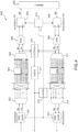
- FIG. 3 shows a diagram of a reflectometry and data transmission system based on an OMTDR type signal.
- the system described in picture 3 comprises a digital modulator 301, or a symbol encoder, for converting a sequence of binary data to be transmitted into complex digital symbols via modulation PSK phase modulation or QAM amplitude modulation.
- the digital complex signal thus formed is transmitted to a serial-parallel multiplexer 302 then to a pre-processing module 303 which performs Hermitian symmetry of the symbols and adds a guard time.
- the symbols are then transmitted to an inverse Fourier transform module 304.
- the symbols are purely real due to the preprocessing operation 303 carried out before the inverse Fourier transform 304.
- a demultiplexer 305 then makes it possible to serialize the real digital signal which is sent to a digital-analog converter 306 then to a coupler 307 to be injected into a transmission line.
- the system also includes a coupler 307 to measure the signal reflected at a point on the line.
- the measured signal undergoes the reverse operations to those carried out in transmission. It is digitized via an analog-to-digital converter 308, then multiplexed via a multiplexer 311.
- a direct Fourier transform module 312 converts the signal into the frequency domain, then a post-processing operation 313 reverses the pre-processing operation. processing 303 carried out on transmission, is applied.
- a demultiplexer 314 makes it possible to serialize the digital complex signal which is then demodulated via a digital demodulator 315 or a symbol decoder.
- the fault analysis is carried out on a real signal by carrying out a correlation 309 between the signal at the input of the digital-analog converter 306 and the signal at the output of the analog-digital converter 308.
- An analysis module 310 makes it possible to characterize the faults possible from the measured reflectogram.
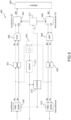
- FIG 4 represents an evolution of the system of picture 3 to which the principles of the invention described in the figure 2 .
- the invention applied to the system of the picture 3 thus consists in directly exploiting a complex signal at the output of the inverse Fourier transform module 304 instead of a real signal as is the case for the picture 3 .
- the pre-processing 303 and post-processing 313 modules used to render the real signal at the output of the IFFT module 304 are removed.
- the redundancy symbols inserted at the input of the module 304 can be removed .
- the complex correlation 210 is performed between the signal at the input of the converter 306 and the signal at the output of the converter 308.
- FIG 5 represents an alternative embodiment of the system described in figure 4 .
- a systolic implementation of the inverse 401 and direct 402 Fourier transform is used so that it is possible to eliminate the multiplexers and demultiplexers 302,305,311,314.
- the correlator 403 can be simplified by directly performing the inverse Fourier transform of the product of the signals taken respectively at the input of the IFFT module 401 and at the output of the FFT module 402.
- FIG. 6 also represents a diagram of a fault detection system according to another variant embodiment of the invention.
- the system 200 described in figure 2 is completed with a phase detector 602 and a phase corrector 603 which have the purpose of correcting the phase errors that the signal may undergo during its propagation in the cable and also of compensating for the phase shifts that may exist between the local oscillators associated with the IQ modulator 204 and the IQ demodulator 206.
- the phase of the signal can be changed during reception.
- a phase shift may also appear between the signal injected into the cable and the measured signal due to the respective frequency translation operations carried out on the injected signal and on the measured signal.
- the reflectometry signal transmitted in baseband is denoted x(t).
- a phase corrector 603 is then applied to the signal at the output of the analog-digital converter 207 before calculating a new reflectogram.
- phase detector 602 may incorporate a loop filter to smooth potential phase error variations and ensure system convergence.
- the phase corrector 603 can be realized by a simple complex multiplier.
- the corrected signal at the output of the phase corrector 603 can thus be correctly demodulated afterwards to recover the binary data transmitted via the signal.
- the various components of the system according to the invention can be implemented by means of software and/or hardware technology.
- the invention can be implemented totally or partially by means of an on-board processor or a specific device.
- the processor may be a generic processor, a specific processor, an application-specific integrated circuit (also known as an ASIC for "Application-Specific Integrated Circuit") or an array of field-programmable gates (also known as the English name of FPGA for “Field-Programmable Gate Array”).
- the system according to the invention can use one or more dedicated electronic circuits or a circuit for general use.
- the technique of the invention can be carried out on a reprogrammable calculation machine (a processor or a microcontroller for example) executing a program comprising a sequence of instructions, or on a dedicated calculation machine (for example a set of logic gates such as an FPGA or an ASIC, or any other hardware module).
- a reprogrammable calculation machine a processor or a microcontroller for example
- a dedicated calculation machine for example a set of logic gates such as an FPGA or an ASIC, or any other hardware module.
Landscapes
- Physics & Mathematics (AREA)
- General Physics & Mathematics (AREA)
- Engineering & Computer Science (AREA)
- Mathematical Physics (AREA)
- Computational Mathematics (AREA)
- Theoretical Computer Science (AREA)
- Mathematical Analysis (AREA)
- Mathematical Optimization (AREA)
- Pure & Applied Mathematics (AREA)
- Data Mining & Analysis (AREA)
- Algebra (AREA)
- Databases & Information Systems (AREA)
- Software Systems (AREA)
- General Engineering & Computer Science (AREA)
- Computing Systems (AREA)
- Measurement Of Resistance Or Impedance (AREA)
- Monitoring And Testing Of Transmission In General (AREA)
Claims (12)
- Reflektometriesystem (200, 400, 600) für die Analyse von Fehlern in einer Übertragungsleitung, in die ein erzeugtes und dann moduliertes komplexes Signal eingespeist wurde, wobei das System Folgendes umfasst:- ein Mittel (205) zum Messen des modulierten komplexen Signals, das sich in der Übertragungsleitung ausbreitet,- einen Demodulator (206) für das gemessene Signal, der zum Produzieren eines demodulierten komplexen Signals ausgelegt ist,- einen komplexen Korrelator (210, 403), der zum Korrelieren des demodulierten komplexen Signals mit einer Kopie des erzeugten komplexen Signals konfiguriert ist, um ein dem Realteil der komplexen Korrelation entsprechendes erstes zeitliches Reflektogramm und ein dem Imaginärteil der komplexen Korrelation entsprechendes zweites zeitliches Reflektogramm zu produzieren,- ein Modul für die gemeinsame Analyse (211) des ersten zeitlichen Reflektogramms und des zweiten zeitlichen Reflektogramms, um das Vorhandensein von Fehlern in der Übertragungsleitung zu identifizieren.
- Reflektometriesystem (200, 400, 600) nach Anspruch 1, wobei das Analysemodul (211) zum Bestimmen eines einzelnen zeitlichen Reflektogramms auf der Basis des Moduls für die komplexe Korrelation konfiguriert ist.
- Reflektometriesystem (600) nach einem der vorherigen Ansprüche, das ferner einen zum Messen der Phase der komplexen Korrelation auf 0 der Zeitabszisse konfigurierten Phasendetektor (602) und einen Phasenkorrektor (603) umfasst, der zum Korrigieren des demodulierten komplexen Signals der vom Phasendetektor (602) gemessenen Phase konfiguriert ist.
- Reflektometriesystem (200, 400, 600) nach einem der vorherigen Ansprüche, das ferner einen Komplexes-Signal-Generator (201, 202), einen Modulator (204), der das komplexe Signal zum Produzieren eines modulierten Signals modulieren kann, und ein Mittel (205) zum Einspeisen des modulierten Signals an einem Punkt der Übertragungsleitung umfasst.
- Reflektometriesystem (200, 400, 600) nach Anspruch 4, das ferner Folgendes umfasst:- einen Lokaloszillator (213), der die Frequenz des Modulators (204) zum Realisieren einer Frequenzumsetzung des Signals regeln kann, und einen Lokaloszillator (213), der die Frequenz des Demodulators (206) zum Realisieren einer Umsetzung des Signals in das Basisband regeln kann,- ein Steuerorgan (212), das den Wert einer Umsetzungsfrequenz regeln kann, in die das Signal umgesetzt wird.
- Reflektometriesystem (200, 400, 600) nach Anspruch 5, wobei das Steuerorgan (212) zum Bestimmen des Wertes der Umsetzungsfrequenz des Signals in Abhängigkeit von mindestens einer Analyse des ersten zeitlichen Reflektogramms und/oder des zweiten zeitlichen Reflektogramms konfiguriert ist.
- Reflektometriesystem (200, 400, 600) nach Anspruch 6, wobei die Analyse des ersten zeitlichen Reflektogramms und/oder des zweiten zeitlichen Reflektogramms sich auf eine Messung der Dämpfung des gemessenen Signals bezieht.
- Reflektometriesystem (400) nach einem der Ansprüche 4 bis 7, wobei das erzeugte komplexe Signal ein Mehrträger-Frequenzsignal ist, wobei das System zu diesem Zweck ferner ein Modul (304, 401) für eine auf das erzeugte komplexe Signal angewendete inverse Fourier-Transformation und ein Modul (312, 402) für eine auf das demodulierte komplexe Signal angewendete Fourier-Transformation umfasst, um ein demoduliertes Frequenzsignal zu erzeugen.
- Reflektometriesystem (400) nach Anspruch 8, wobei der komplexe Korrelator (403) einen Korrelator des erzeugten Frequenzsignals mit dem demodulierten Frequenzdomänensignal und einer auf das Ergebnis der Korrelation angewendeten inversen Fouriertransformation umfasst.
- Reflektometriesystem nach einem der Ansprüche 4 bis 9, wobei der Komplexes-Signal-Generator eine Schnittstelle (201) zum Empfangen von zu übertragenden digitalen Daten und einen Modulator (202, 301) zum Umwandeln der digitalen Daten in komplexe Symbole umfasst, wobei das System ferner einen Empfänger (208, 315) zum Umwandeln des komplexen demodulierten Signals in empfangene digitale Daten umfasst.
- Reflektometriesystem (200) nach Anspruch 10, das ferner einen Encoder (202) für die zu übertragenden digitalen Daten und einen Decoder (208) für die empfangenen digitalen Daten umfasst, wobei das Steuerorgan (212) zum Bestimmen der Codierrate des Encoders und des Decoders konfiguriert ist.
- Reflektometriesystem (200) nach Anspruch 11, das ferner ein Modul zum Berechnen der Fehlerrate zwischen den decodierten digitalen Daten und den zu übertragenden digitalen Daten umfasst, wobei das Steuerorgan (212) zum Bestimmen des Wertes der Umsetzungsfrequenz des Signals und/oder der Codierrate in Abhängigkeit von mindestens der berechneten Fehlerrate konfiguriert ist.
Applications Claiming Priority (2)
| Application Number | Priority Date | Filing Date | Title |
|---|---|---|---|
| FR1662308A FR3060128B1 (fr) | 2016-12-12 | 2016-12-12 | Systeme et procede de detection de defauts dans une ligne de transmission, par utilisation d'un signal complexe |
| PCT/EP2017/080767 WO2018108526A1 (fr) | 2016-12-12 | 2017-11-29 | Systeme de detection de defauts dans une ligne de transmission, par utilisation d'un signal complexe |
Publications (2)
| Publication Number | Publication Date |
|---|---|
| EP3552032A1 EP3552032A1 (de) | 2019-10-16 |
| EP3552032B1 true EP3552032B1 (de) | 2023-03-29 |
Family
ID=57909752
Family Applications (1)
| Application Number | Title | Priority Date | Filing Date |
|---|---|---|---|
| EP17804207.3A Active EP3552032B1 (de) | 2016-12-12 | 2017-11-29 | System zur erkennung von defekten in einer übertragungsleitung unter verwendung eines komplexen signals |
Country Status (4)
| Country | Link |
|---|---|
| US (1) | US11156652B2 (de) |
| EP (1) | EP3552032B1 (de) |
| FR (1) | FR3060128B1 (de) |
| WO (1) | WO2018108526A1 (de) |
Families Citing this family (12)
| Publication number | Priority date | Publication date | Assignee | Title |
|---|---|---|---|---|
| FR3082947B1 (fr) | 2018-06-26 | 2020-06-12 | Commissariat A L'energie Atomique Et Aux Energies Alternatives | Procede de caracterisation d'un defaut dans un reseau de lignes de transmission de topologie inconnue |
| FR3083323B1 (fr) * | 2018-06-29 | 2020-06-19 | Commissariat A L'energie Atomique Et Aux Energies Alternatives | Procede et systeme de caracterisation d'un defaut dans un reseau de lignes de transmission, par retournement temporel |
| FR3093811B1 (fr) * | 2019-03-15 | 2021-05-14 | Safran Electrical & Power | Détection d’arc par reflectometrie |
| CN110118912B (zh) * | 2019-04-23 | 2022-02-01 | 武汉理工大学 | 一种基于灰色关联分析的经消弧线圈装置接地配电网单相接地故障选线方法 |
| US11533105B1 (en) * | 2020-06-01 | 2022-12-20 | Cable Television Laboratories, Inc. | Systems and methods for determining reflection and transmission coefficients |
| US11609258B2 (en) * | 2020-11-27 | 2023-03-21 | Uif (University Industry Foundation), Yonsei University | Apparatus and method for detecting cable fault based on reflectometry using AI |
| CN117296253A (zh) * | 2021-06-02 | 2023-12-26 | 住友电气工业株式会社 | 检测装置及检测方法 |
| FR3127581B1 (fr) * | 2021-09-29 | 2023-09-22 | Commissariat Energie Atomique | Méthode de génération d’un signal de réflectométrie multiporteuses ayant la forme d’un signal de type « chirp » |
| US20250060401A1 (en) * | 2022-01-19 | 2025-02-20 | Sumitomo Electric Industries, Ltd. | Detection device and detection method |
| FR3136859B1 (fr) * | 2022-06-21 | 2024-06-28 | Commissariat Energie Atomique | Méthode de détection et localisation de défauts francs ou de terminaison pour un câble composé de plusieurs tronçons de câbles inhomogènes |
| US20250373232A1 (en) * | 2024-05-29 | 2025-12-04 | Microchip Technology Incorporated | Use of pulse width modulation to generate excitation pulses offset from sampling pulses |
| CN119939172B (zh) * | 2025-04-07 | 2025-07-22 | 杭州巨骐信息科技股份有限公司 | 一种基于非均匀fdm-nlfm的电缆防外破方法及系统 |
Family Cites Families (8)
| Publication number | Priority date | Publication date | Assignee | Title |
|---|---|---|---|---|
| US4630228A (en) * | 1982-06-28 | 1986-12-16 | Systron-Donner Corporation | Transmission line analyzer for automatically identifying the severities and locations of multiple mismatches |
| FR2931323A1 (fr) * | 2008-05-14 | 2009-11-20 | Commissariat Energie Atomique | Dispositif et procede de reflectometrie multiporteuse pour le diagnostic en ligne d'au moins une ligne de transmission |
| FR2937146B1 (fr) * | 2008-10-15 | 2011-02-11 | Commissariat Energie Atomique | Dispositif et procede de reflectometrie distribuee pour le diagnostic d'un reseau de transmission |
| US9244117B2 (en) | 2013-03-15 | 2016-01-26 | Livewire Innovation, Inc. | Systems and methods for implementing S/SSTDR measurements |
| FR3006769B1 (fr) * | 2013-06-11 | 2016-12-02 | Commissariat Energie Atomique | Procede de reflectometrie pour l'identification de defauts non francs impactant un cable |
| FR3012617A1 (fr) * | 2013-10-31 | 2015-05-01 | Commissariat Energie Atomique | Methode de localisation de defauts electriques au sein d'un reseau de lignes de transmission et systeme associe |
| FR3012616B1 (fr) * | 2013-10-31 | 2019-05-31 | Commissariat A L'energie Atomique Et Aux Energies Alternatives | Methode de generation d'un signal de reflectometrie multi-porteuses pour une mise en œuvre dans un systeme distribue |
| FR3019307B1 (fr) | 2014-03-26 | 2016-03-18 | Labinal Power Systems | Procede de surveillance de l'etat de sante d'un cable electrique |
-
2016
- 2016-12-12 FR FR1662308A patent/FR3060128B1/fr active Active
-
2017
- 2017-11-29 EP EP17804207.3A patent/EP3552032B1/de active Active
- 2017-11-29 US US16/467,973 patent/US11156652B2/en not_active Expired - Fee Related
- 2017-11-29 WO PCT/EP2017/080767 patent/WO2018108526A1/fr not_active Ceased
Also Published As
| Publication number | Publication date |
|---|---|
| FR3060128B1 (fr) | 2019-03-15 |
| WO2018108526A1 (fr) | 2018-06-21 |
| US11156652B2 (en) | 2021-10-26 |
| US20200116777A1 (en) | 2020-04-16 |
| EP3552032A1 (de) | 2019-10-16 |
| FR3060128A1 (fr) | 2018-06-15 |
Similar Documents
| Publication | Publication Date | Title |
|---|---|---|
| EP3552032B1 (de) | System zur erkennung von defekten in einer übertragungsleitung unter verwendung eines komplexen signals | |
| EP2503750B1 (de) | Verarbeitungsverfahren eines Multicarrier-Signals mit Filterbänken für die Präambelsynchronisation | |
| EP3063546B1 (de) | Verfahren zur erzeugung eines mehrträger-reflektometriesignals zur implementierung in einem verteilten system | |
| EP0879523B1 (de) | Verfahren und Apparat für Zeitsynchronisierung in einem Empfänger für ein Mehrträgersignal | |
| EP0441730B2 (de) | Verfahren zur Datenverbreitung mit Zeit-Frequenzverschachtelung mit Verwendung von Bezugsfrequenzsignalen | |
| US20040146003A1 (en) | Method for frame and frequency synchronization of an ofdm signal and method for transmitting an ofdm signal | |
| FR2892824A1 (fr) | Procede et dispositif pour le test d'une ligne de transmission par reflexion dans le domaine temporel | |
| JP2018042235A (ja) | ノイズ強度検出装置、ノイズ強度検出方法及びコヒーレント光受信機 | |
| WO2018192832A1 (fr) | Procede et systeme de detection d'un defaut dans une ligne de transmission a partir d'une mesure de phase | |
| EP3201638A1 (de) | Verfahren zur analyse eines kabels, basierend auf einer selbstanpassenden korrelation, zum nachweis von nicht eindeutigen defekten | |
| EP2732592B1 (de) | Verfahren und modul zur schätzung der frequenzverzerrung in einem system für digitale telekommunikation | |
| EP4160230B1 (de) | Methode zur erzeugung eines mehrträger-reflektometriesignals, das die form eines chirp-signals hat | |
| FR2835136A1 (fr) | Demodulateur cofdm a positionnement optimal de fenetre d'analyse fft | |
| EP2854354B1 (de) | Verfahren zur Bestimmung von Störstellen eines Sende- und eines Empfangswegs eines Geräts und dazugehörige Vorrichtung | |
| FR3097971A1 (fr) | Méthode de réduction de la puissance crête d’un signal de réflectométrie multi-porteuses | |
| EP3131229B1 (de) | Verfahren zur erzeugung eines gruppensicherheitsschlüssels, der auf der physikalischen funkschicht basiert, und entsprechendes drahtloses endgerät | |
| FR3012617A1 (fr) | Methode de localisation de defauts electriques au sein d'un reseau de lignes de transmission et systeme associe | |
| FR3117603A1 (fr) | Méthode et système de réflectométrie multi-porteuses avec prise en compte de l’atténuation et de la distorsion du signal | |
| US11463169B2 (en) | Wavelength dispersion amount estimation apparatus | |
| CN101371538B (zh) | 对信道脉冲响应的长度的估计 | |
| Gargouri et al. | Reflectometry architecture for enhanced fault localization based on low PAPR chirp-OMTDR | |
| EP2327191B1 (de) | Verfahren zur Blindmessung von OFDM-Signalparametern durch adaptierte Filterung | |
| De Vito et al. | Wireline channel estimation by compressive sampling for physical layer testing | |
| EP4105673A1 (de) | Methode zur einschätzung der eigenschaften eines gepulsten ultrabreitbandsignals, das von mehreren antennen ausgesendet wird | |
| JP4102348B2 (ja) | Ofdm波遅延プロファイル測定装置 |
Legal Events
| Date | Code | Title | Description |
|---|---|---|---|
| STAA | Information on the status of an ep patent application or granted ep patent |
Free format text: STATUS: UNKNOWN |
|
| STAA | Information on the status of an ep patent application or granted ep patent |
Free format text: STATUS: THE INTERNATIONAL PUBLICATION HAS BEEN MADE |
|
| PUAI | Public reference made under article 153(3) epc to a published international application that has entered the european phase |
Free format text: ORIGINAL CODE: 0009012 |
|
| STAA | Information on the status of an ep patent application or granted ep patent |
Free format text: STATUS: REQUEST FOR EXAMINATION WAS MADE |
|
| 17P | Request for examination filed |
Effective date: 20190604 |
|
| AK | Designated contracting states |
Kind code of ref document: A1 Designated state(s): AL AT BE BG CH CY CZ DE DK EE ES FI FR GB GR HR HU IE IS IT LI LT LU LV MC MK MT NL NO PL PT RO RS SE SI SK SM TR |
|
| AX | Request for extension of the european patent |
Extension state: BA ME |
|
| DAV | Request for validation of the european patent (deleted) | ||
| DAX | Request for extension of the european patent (deleted) | ||
| GRAP | Despatch of communication of intention to grant a patent |
Free format text: ORIGINAL CODE: EPIDOSNIGR1 |
|
| STAA | Information on the status of an ep patent application or granted ep patent |
Free format text: STATUS: GRANT OF PATENT IS INTENDED |
|
| INTG | Intention to grant announced |
Effective date: 20221020 |
|
| GRAS | Grant fee paid |
Free format text: ORIGINAL CODE: EPIDOSNIGR3 |
|
| GRAA | (expected) grant |
Free format text: ORIGINAL CODE: 0009210 |
|
| STAA | Information on the status of an ep patent application or granted ep patent |
Free format text: STATUS: THE PATENT HAS BEEN GRANTED |
|
| AK | Designated contracting states |
Kind code of ref document: B1 Designated state(s): AL AT BE BG CH CY CZ DE DK EE ES FI FR GB GR HR HU IE IS IT LI LT LU LV MC MK MT NL NO PL PT RO RS SE SI SK SM TR |
|
| REG | Reference to a national code |
Ref country code: CH Ref legal event code: EP |
|
| REG | Reference to a national code |
Ref country code: DE Ref legal event code: R096 Ref document number: 602017067235 Country of ref document: DE |
|
| REG | Reference to a national code |
Ref country code: AT Ref legal event code: REF Ref document number: 1557067 Country of ref document: AT Kind code of ref document: T Effective date: 20230415 |
|
| REG | Reference to a national code |
Ref country code: IE Ref legal event code: FG4D Free format text: LANGUAGE OF EP DOCUMENT: FRENCH |
|
| REG | Reference to a national code |
Ref country code: LT Ref legal event code: MG9D |
|
| PG25 | Lapsed in a contracting state [announced via postgrant information from national office to epo] |
Ref country code: RS Free format text: LAPSE BECAUSE OF FAILURE TO SUBMIT A TRANSLATION OF THE DESCRIPTION OR TO PAY THE FEE WITHIN THE PRESCRIBED TIME-LIMIT Effective date: 20230329 Ref country code: NO Free format text: LAPSE BECAUSE OF FAILURE TO SUBMIT A TRANSLATION OF THE DESCRIPTION OR TO PAY THE FEE WITHIN THE PRESCRIBED TIME-LIMIT Effective date: 20230629 Ref country code: LV Free format text: LAPSE BECAUSE OF FAILURE TO SUBMIT A TRANSLATION OF THE DESCRIPTION OR TO PAY THE FEE WITHIN THE PRESCRIBED TIME-LIMIT Effective date: 20230329 Ref country code: LT Free format text: LAPSE BECAUSE OF FAILURE TO SUBMIT A TRANSLATION OF THE DESCRIPTION OR TO PAY THE FEE WITHIN THE PRESCRIBED TIME-LIMIT Effective date: 20230329 Ref country code: HR Free format text: LAPSE BECAUSE OF FAILURE TO SUBMIT A TRANSLATION OF THE DESCRIPTION OR TO PAY THE FEE WITHIN THE PRESCRIBED TIME-LIMIT Effective date: 20230329 |
|
| REG | Reference to a national code |
Ref country code: NL Ref legal event code: MP Effective date: 20230329 |
|
| REG | Reference to a national code |
Ref country code: AT Ref legal event code: MK05 Ref document number: 1557067 Country of ref document: AT Kind code of ref document: T Effective date: 20230329 |
|
| PG25 | Lapsed in a contracting state [announced via postgrant information from national office to epo] |
Ref country code: SE Free format text: LAPSE BECAUSE OF FAILURE TO SUBMIT A TRANSLATION OF THE DESCRIPTION OR TO PAY THE FEE WITHIN THE PRESCRIBED TIME-LIMIT Effective date: 20230329 Ref country code: NL Free format text: LAPSE BECAUSE OF FAILURE TO SUBMIT A TRANSLATION OF THE DESCRIPTION OR TO PAY THE FEE WITHIN THE PRESCRIBED TIME-LIMIT Effective date: 20230329 Ref country code: GR Free format text: LAPSE BECAUSE OF FAILURE TO SUBMIT A TRANSLATION OF THE DESCRIPTION OR TO PAY THE FEE WITHIN THE PRESCRIBED TIME-LIMIT Effective date: 20230630 Ref country code: FI Free format text: LAPSE BECAUSE OF FAILURE TO SUBMIT A TRANSLATION OF THE DESCRIPTION OR TO PAY THE FEE WITHIN THE PRESCRIBED TIME-LIMIT Effective date: 20230329 |
|
| PG25 | Lapsed in a contracting state [announced via postgrant information from national office to epo] |
Ref country code: SM Free format text: LAPSE BECAUSE OF FAILURE TO SUBMIT A TRANSLATION OF THE DESCRIPTION OR TO PAY THE FEE WITHIN THE PRESCRIBED TIME-LIMIT Effective date: 20230329 Ref country code: RO Free format text: LAPSE BECAUSE OF FAILURE TO SUBMIT A TRANSLATION OF THE DESCRIPTION OR TO PAY THE FEE WITHIN THE PRESCRIBED TIME-LIMIT Effective date: 20230329 Ref country code: PT Free format text: LAPSE BECAUSE OF FAILURE TO SUBMIT A TRANSLATION OF THE DESCRIPTION OR TO PAY THE FEE WITHIN THE PRESCRIBED TIME-LIMIT Effective date: 20230731 Ref country code: ES Free format text: LAPSE BECAUSE OF FAILURE TO SUBMIT A TRANSLATION OF THE DESCRIPTION OR TO PAY THE FEE WITHIN THE PRESCRIBED TIME-LIMIT Effective date: 20230329 Ref country code: EE Free format text: LAPSE BECAUSE OF FAILURE TO SUBMIT A TRANSLATION OF THE DESCRIPTION OR TO PAY THE FEE WITHIN THE PRESCRIBED TIME-LIMIT Effective date: 20230329 Ref country code: AT Free format text: LAPSE BECAUSE OF FAILURE TO SUBMIT A TRANSLATION OF THE DESCRIPTION OR TO PAY THE FEE WITHIN THE PRESCRIBED TIME-LIMIT Effective date: 20230329 |
|
| PG25 | Lapsed in a contracting state [announced via postgrant information from national office to epo] |
Ref country code: SK Free format text: LAPSE BECAUSE OF FAILURE TO SUBMIT A TRANSLATION OF THE DESCRIPTION OR TO PAY THE FEE WITHIN THE PRESCRIBED TIME-LIMIT Effective date: 20230329 Ref country code: PL Free format text: LAPSE BECAUSE OF FAILURE TO SUBMIT A TRANSLATION OF THE DESCRIPTION OR TO PAY THE FEE WITHIN THE PRESCRIBED TIME-LIMIT Effective date: 20230329 Ref country code: IS Free format text: LAPSE BECAUSE OF FAILURE TO SUBMIT A TRANSLATION OF THE DESCRIPTION OR TO PAY THE FEE WITHIN THE PRESCRIBED TIME-LIMIT Effective date: 20230729 |
|
| REG | Reference to a national code |
Ref country code: DE Ref legal event code: R097 Ref document number: 602017067235 Country of ref document: DE |
|
| PG25 | Lapsed in a contracting state [announced via postgrant information from national office to epo] |
Ref country code: DK Free format text: LAPSE BECAUSE OF FAILURE TO SUBMIT A TRANSLATION OF THE DESCRIPTION OR TO PAY THE FEE WITHIN THE PRESCRIBED TIME-LIMIT Effective date: 20230329 Ref country code: CZ Free format text: LAPSE BECAUSE OF FAILURE TO SUBMIT A TRANSLATION OF THE DESCRIPTION OR TO PAY THE FEE WITHIN THE PRESCRIBED TIME-LIMIT Effective date: 20230329 |
|
| PLBE | No opposition filed within time limit |
Free format text: ORIGINAL CODE: 0009261 |
|
| STAA | Information on the status of an ep patent application or granted ep patent |
Free format text: STATUS: NO OPPOSITION FILED WITHIN TIME LIMIT |
|
| 26N | No opposition filed |
Effective date: 20240103 |
|
| PG25 | Lapsed in a contracting state [announced via postgrant information from national office to epo] |
Ref country code: SI Free format text: LAPSE BECAUSE OF FAILURE TO SUBMIT A TRANSLATION OF THE DESCRIPTION OR TO PAY THE FEE WITHIN THE PRESCRIBED TIME-LIMIT Effective date: 20230329 |
|
| PG25 | Lapsed in a contracting state [announced via postgrant information from national office to epo] |
Ref country code: SI Free format text: LAPSE BECAUSE OF FAILURE TO SUBMIT A TRANSLATION OF THE DESCRIPTION OR TO PAY THE FEE WITHIN THE PRESCRIBED TIME-LIMIT Effective date: 20230329 Ref country code: IT Free format text: LAPSE BECAUSE OF FAILURE TO SUBMIT A TRANSLATION OF THE DESCRIPTION OR TO PAY THE FEE WITHIN THE PRESCRIBED TIME-LIMIT Effective date: 20230329 |
|
| REG | Reference to a national code |
Ref country code: DE Ref legal event code: R119 Ref document number: 602017067235 Country of ref document: DE |
|
| REG | Reference to a national code |
Ref country code: CH Ref legal event code: PL |
|
| PG25 | Lapsed in a contracting state [announced via postgrant information from national office to epo] |
Ref country code: MC Free format text: LAPSE BECAUSE OF FAILURE TO SUBMIT A TRANSLATION OF THE DESCRIPTION OR TO PAY THE FEE WITHIN THE PRESCRIBED TIME-LIMIT Effective date: 20230329 |
|
| PG25 | Lapsed in a contracting state [announced via postgrant information from national office to epo] |
Ref country code: LU Free format text: LAPSE BECAUSE OF NON-PAYMENT OF DUE FEES Effective date: 20231129 |
|
| PG25 | Lapsed in a contracting state [announced via postgrant information from national office to epo] |
Ref country code: CH Free format text: LAPSE BECAUSE OF NON-PAYMENT OF DUE FEES Effective date: 20231130 |
|
| GBPC | Gb: european patent ceased through non-payment of renewal fee |
Effective date: 20231129 |
|
| PG25 | Lapsed in a contracting state [announced via postgrant information from national office to epo] |
Ref country code: MC Free format text: LAPSE BECAUSE OF FAILURE TO SUBMIT A TRANSLATION OF THE DESCRIPTION OR TO PAY THE FEE WITHIN THE PRESCRIBED TIME-LIMIT Effective date: 20230329 Ref country code: LU Free format text: LAPSE BECAUSE OF NON-PAYMENT OF DUE FEES Effective date: 20231129 Ref country code: CH Free format text: LAPSE BECAUSE OF NON-PAYMENT OF DUE FEES Effective date: 20231130 |
|
| REG | Reference to a national code |
Ref country code: BE Ref legal event code: MM Effective date: 20231130 |
|
| REG | Reference to a national code |
Ref country code: IE Ref legal event code: MM4A |
|
| PG25 | Lapsed in a contracting state [announced via postgrant information from national office to epo] |
Ref country code: IE Free format text: LAPSE BECAUSE OF NON-PAYMENT OF DUE FEES Effective date: 20231129 Ref country code: DE Free format text: LAPSE BECAUSE OF NON-PAYMENT OF DUE FEES Effective date: 20240601 |
|
| PG25 | Lapsed in a contracting state [announced via postgrant information from national office to epo] |
Ref country code: GB Free format text: LAPSE BECAUSE OF NON-PAYMENT OF DUE FEES Effective date: 20231129 |
|
| PG25 | Lapsed in a contracting state [announced via postgrant information from national office to epo] |
Ref country code: BE Free format text: LAPSE BECAUSE OF NON-PAYMENT OF DUE FEES Effective date: 20231130 |
|
| PG25 | Lapsed in a contracting state [announced via postgrant information from national office to epo] |
Ref country code: IE Free format text: LAPSE BECAUSE OF NON-PAYMENT OF DUE FEES Effective date: 20231129 Ref country code: GB Free format text: LAPSE BECAUSE OF NON-PAYMENT OF DUE FEES Effective date: 20231129 Ref country code: DE Free format text: LAPSE BECAUSE OF NON-PAYMENT OF DUE FEES Effective date: 20240601 Ref country code: BE Free format text: LAPSE BECAUSE OF NON-PAYMENT OF DUE FEES Effective date: 20231130 |
|
| PG25 | Lapsed in a contracting state [announced via postgrant information from national office to epo] |
Ref country code: BG Free format text: LAPSE BECAUSE OF FAILURE TO SUBMIT A TRANSLATION OF THE DESCRIPTION OR TO PAY THE FEE WITHIN THE PRESCRIBED TIME-LIMIT Effective date: 20230329 |
|
| PG25 | Lapsed in a contracting state [announced via postgrant information from national office to epo] |
Ref country code: BG Free format text: LAPSE BECAUSE OF FAILURE TO SUBMIT A TRANSLATION OF THE DESCRIPTION OR TO PAY THE FEE WITHIN THE PRESCRIBED TIME-LIMIT Effective date: 20230329 |
|
| PG25 | Lapsed in a contracting state [announced via postgrant information from national office to epo] |
Ref country code: CY Free format text: LAPSE BECAUSE OF FAILURE TO SUBMIT A TRANSLATION OF THE DESCRIPTION OR TO PAY THE FEE WITHIN THE PRESCRIBED TIME-LIMIT; INVALID AB INITIO Effective date: 20171129 |
|
| PG25 | Lapsed in a contracting state [announced via postgrant information from national office to epo] |
Ref country code: HU Free format text: LAPSE BECAUSE OF FAILURE TO SUBMIT A TRANSLATION OF THE DESCRIPTION OR TO PAY THE FEE WITHIN THE PRESCRIBED TIME-LIMIT; INVALID AB INITIO Effective date: 20171129 |
|
| PG25 | Lapsed in a contracting state [announced via postgrant information from national office to epo] |
Ref country code: TR Free format text: LAPSE BECAUSE OF FAILURE TO SUBMIT A TRANSLATION OF THE DESCRIPTION OR TO PAY THE FEE WITHIN THE PRESCRIBED TIME-LIMIT Effective date: 20230329 |
|
| PGFP | Annual fee paid to national office [announced via postgrant information from national office to epo] |
Ref country code: FR Payment date: 20251125 Year of fee payment: 9 |