EP3552032B1 - System for detecting faults in a transmission line by using a complex signal - Google Patents
System for detecting faults in a transmission line by using a complex signal Download PDFInfo
- Publication number
- EP3552032B1 EP3552032B1 EP17804207.3A EP17804207A EP3552032B1 EP 3552032 B1 EP3552032 B1 EP 3552032B1 EP 17804207 A EP17804207 A EP 17804207A EP 3552032 B1 EP3552032 B1 EP 3552032B1
- Authority
- EP
- European Patent Office
- Prior art keywords
- signal
- complex
- frequency
- reflectogram
- domain
- Prior art date
- Legal status (The legal status is an assumption and is not a legal conclusion. Google has not performed a legal analysis and makes no representation as to the accuracy of the status listed.)
- Active
Links
- 230000005540 biological transmission Effects 0.000 title claims description 41
- 238000002310 reflectometry Methods 0.000 claims description 45
- 238000004458 analytical method Methods 0.000 claims description 28
- 230000017105 transposition Effects 0.000 claims description 23
- 238000005259 measurement Methods 0.000 claims description 8
- 230000007246 mechanism Effects 0.000 claims description 5
- 230000001902 propagating effect Effects 0.000 claims description 2
- 238000004891 communication Methods 0.000 description 16
- 238000010586 diagram Methods 0.000 description 14
- 238000001514 detection method Methods 0.000 description 10
- 238000002347 injection Methods 0.000 description 10
- 239000007924 injection Substances 0.000 description 10
- 230000007547 defect Effects 0.000 description 9
- 230000002123 temporal effect Effects 0.000 description 8
- 238000004364 calculation method Methods 0.000 description 6
- 238000000034 method Methods 0.000 description 5
- 238000003745 diagnosis Methods 0.000 description 4
- 238000007781 pre-processing Methods 0.000 description 4
- 230000002238 attenuated effect Effects 0.000 description 3
- 230000008901 benefit Effects 0.000 description 3
- 230000015556 catabolic process Effects 0.000 description 3
- 238000012512 characterization method Methods 0.000 description 3
- 238000006731 degradation reaction Methods 0.000 description 3
- 238000005516 engineering process Methods 0.000 description 3
- 230000010363 phase shift Effects 0.000 description 3
- 238000006243 chemical reaction Methods 0.000 description 2
- 230000002452 interceptive effect Effects 0.000 description 2
- 238000012805 post-processing Methods 0.000 description 2
- 230000004044 response Effects 0.000 description 2
- 238000005070 sampling Methods 0.000 description 2
- 230000003595 spectral effect Effects 0.000 description 2
- 238000013519 translation Methods 0.000 description 2
- 230000008859 change Effects 0.000 description 1
- 238000013461 design Methods 0.000 description 1
- 238000011161 development Methods 0.000 description 1
- 230000036541 health Effects 0.000 description 1
- 230000003116 impacting effect Effects 0.000 description 1
- 230000010365 information processing Effects 0.000 description 1
- 230000004807 localization Effects 0.000 description 1
- 238000012545 processing Methods 0.000 description 1
- 230000002441 reversible effect Effects 0.000 description 1
- 239000000243 solution Substances 0.000 description 1
- 238000001228 spectrum Methods 0.000 description 1
Images


Classifications
-
- G—PHYSICS
- G01—MEASURING; TESTING
- G01R—MEASURING ELECTRIC VARIABLES; MEASURING MAGNETIC VARIABLES
- G01R31/00—Arrangements for testing electric properties; Arrangements for locating electric faults; Arrangements for electrical testing characterised by what is being tested not provided for elsewhere
- G01R31/08—Locating faults in cables, transmission lines, or networks
- G01R31/11—Locating faults in cables, transmission lines, or networks using pulse reflection methods
-
- G—PHYSICS
- G01—MEASURING; TESTING
- G01R—MEASURING ELECTRIC VARIABLES; MEASURING MAGNETIC VARIABLES
- G01R31/00—Arrangements for testing electric properties; Arrangements for locating electric faults; Arrangements for electrical testing characterised by what is being tested not provided for elsewhere
- G01R31/08—Locating faults in cables, transmission lines, or networks
- G01R31/081—Locating faults in cables, transmission lines, or networks according to type of conductors
- G01R31/086—Locating faults in cables, transmission lines, or networks according to type of conductors in power transmission or distribution networks, i.e. with interconnected conductors
-
- G—PHYSICS
- G06—COMPUTING; CALCULATING OR COUNTING
- G06F—ELECTRIC DIGITAL DATA PROCESSING
- G06F17/00—Digital computing or data processing equipment or methods, specially adapted for specific functions
- G06F17/10—Complex mathematical operations
- G06F17/15—Correlation function computation including computation of convolution operations
-
- G—PHYSICS
- G01—MEASURING; TESTING
- G01R—MEASURING ELECTRIC VARIABLES; MEASURING MAGNETIC VARIABLES
- G01R31/00—Arrangements for testing electric properties; Arrangements for locating electric faults; Arrangements for electrical testing characterised by what is being tested not provided for elsewhere
- G01R31/28—Testing of electronic circuits, e.g. by signal tracer
- G01R31/2832—Specific tests of electronic circuits not provided for elsewhere
- G01R31/2836—Fault-finding or characterising
- G01R31/2839—Fault-finding or characterising using signal generators, power supplies or circuit analysers
-
- G—PHYSICS
- G01—MEASURING; TESTING
- G01R—MEASURING ELECTRIC VARIABLES; MEASURING MAGNETIC VARIABLES
- G01R31/00—Arrangements for testing electric properties; Arrangements for locating electric faults; Arrangements for electrical testing characterised by what is being tested not provided for elsewhere
- G01R31/50—Testing of electric apparatus, lines, cables or components for short-circuits, continuity, leakage current or incorrect line connections
- G01R31/58—Testing of lines, cables or conductors
Definitions
- the invention relates to the field of the analysis of faults impacting transmission lines, such as electric cables and more particularly communication cables.
- the invention relates to the particular field of reflectometry applied to wired diagnostics which encompasses the field of detection, location and characterization of faults in simple transmission lines or complex wired networks.
- Known reflectometry methods operate according to the following method.
- a controlled reference signal for example a pulsed signal or even a multi-carrier signal, is injected at one end of the cable to be tested. More generally, the reference signal used is chosen according to its intercorrelation properties. The signal propagates along the cable and is reflected on the singularities it contains.
- a singularity in a cable corresponds to a break in the signal propagation conditions in this cable. It most often results from a fault which locally modifies the characteristic impedance of the cable by causing a discontinuity in its linear parameters.
- a defect can result from any type of local degradation of a cable, pinching, rubbing or surface degradation of the cable sheath.
- the reflected signal is back-propagated to the injection point, then analyzed by the reflectometry system.
- the delay between the injected signal and the reflected signal makes it possible to locate a singularity, corresponding to an electrical fault, in the cable.
- a fault can result from a short circuit, an open circuit or even local degradation of the cable or even a simple pinching of the cable.
- Reflectometry is based on the principle of measuring an echo of the signal injected on a singularity of the analyzed cable.
- areas of the cable called blind areas, where an echo cannot be measured. These zones depend on the wavelength of the signal, therefore on its frequency, on the speed of propagation of the signal, on the sampling frequency of the measured signal and on the distance between the point of injection of the signal and the point where lies the singularity. If a defect appears in a blind zone, it is therefore not possible to detect its presence using a conventional reflectometry method.
- the detection of faults with precision requires the use of a high frequency signal so that the wavelength of the injected signal coincides with the physical dimensions of the faults in the cable.
- the analog-digital converters which make it possible to inject and measure a high-frequency signal are expensive.
- the transmission channels corresponding to the different cable technologies targeted by the reflectometry applications are most often very frequency selective and therefore do not allow broadband observation and diagnosis. Certain frequency bands can be significantly attenuated or disturbed, which can make the signal measured by the reflectometry system unusable or in any case complicate the identification of any faults.
- Another problem also relates to the compatibility of a reflectometry system with a communication cable or network of cables.
- the injected reflectometry signal can interfere with the communication signals also transmitted via these cables, which makes diagnosis impossible while the communication network is in operation.
- Certain frequency bands cannot be used for diagnosis by reflectometry because they are reserved for the transmission of data.
- Reflectometry methods and systems for measuring the state of health of a cable and characterizing the presence of any faults have been the subject of numerous publications.
- the invention makes it possible to solve the problem of blind zones by using a complex reflectometry signal modulated in quadrature and by jointly exploiting the reflectograms obtained for the real channel and the imaginary channel of the measured signal.
- the invention also makes it possible to carry out a broadband frequency analysis of a cable by using a frequency transposition of the signal injected into the cable.
- the use of a complex signal also allows simultaneous operation of data communication via the cable to be analyzed and analysis of cable faults by reflectometry with a data transmission rate doubled compared to a real signal.
- the analysis module is configured to determine a unique temporal reflectogram from the module of the complex correlation.
- the system according to the invention further comprises a phase detector configured to measure the phase of the complex correlation at the time abscissa 0 and a phase corrector configured to correct the demodulated complex signal of the measured phase by the phase detector.
- the system according to the invention further comprises a complex signal generator, a modulator capable of modulating the complex signal to produce a modulated signal and means for injecting the modulated signal at a point on the transmission line. .
- control unit is configured to determine the value of the transposition frequency of the signal as a function of at least one analysis of the first time reflectogram and/or of the second time reflectogram.
- the analysis of the first temporal reflectogram and/or of the second temporal reflectogram relates to a measurement of the attenuation of the measured signal.
- the generated complex signal is a multi-carrier frequency signal, said system further comprising for this purpose an inverse Fourier transform module applied to the generated complex signal and a Fourier transform module applied to the demodulated complex signal.
- the complex correlator comprises a correlator of the frequency signal generated with the demodulated frequency signal and an inverse Fourier transform applied to the result of the correlation.
- the complex signal generator comprises an interface for receiving digital data to be transmitted and a modulator for converting the digital data into complex symbols, said system further comprising a receiver for converting the complex demodulated signal into digital data received.
- the system according to the invention further comprises an encoder for the digital data to be transmitted and a decoder for the digital data received, the control unit being configured to determine the coding rate of the encoder and of the decoder .
- the system according to the invention further comprises a module for calculating the rate of errors between the decoded digital data and the digital data to be transmitted, the control member being configured to determine the value of the frequency transposition of the signal and/or the coding rate as a function of at least the calculated error rate.
- FIG. 1 diagrams a system 100 for detecting faults in a transmission line, by reflectometry, according to a principle known from the prior art.
- the system 100 mainly comprises a generator 102 of a reference signal from the parameters 101 of the signal.
- the reference signal can be time or frequency. It can be a simple temporal pulse or a more elaborate signal insofar as the latter has good autocorrelation properties, that is to say that the result of an autocorrelation calculation applied to this signal gives a significant amplitude peak that can be identified and detected.
- the signal used can be of the OMTDR (Orthogonal Multi-tone Time Domain Reflectometry) or MCTDR (MultiCarrier Time Domain Reflectometry) type.
- a digital-analog converter 103 makes it possible to convert the digital signal into an analog signal which is then injected at a point on the transmission line (not shown in figure 1 ) via a coupler 104.
- the system 100 then comprises a measurement part which comprises a coupler 104 (identical to the previous one or distinct) to measure, at a point on the line, the signal reflected and back-propagated in the transmission line.
- the measured analog signal is digitally converted via an analog-digital converter 105.
- the digital signal can be filtered 106 or averaged in order to limit the influence of the measurement noise, then a correlator 107 is in charge of performing a correlation between the measured signal and the generated signal, for different time offsets, to produce a time domain reflectogram.
- An example of a time domain reflectogram is given at the bottom of the figure 1 . It comprises a certain number of amplitude peaks which translate impedance discontinuities in the transmission line.
- the temporal abscissas of the peaks on the reflectogram correspond to positions in the transmission line.
- the reflectogram obtained can be corrected 108 by calculating its difference with respect to a reference reflectogram 109.
- a first peak P 0 corresponding to the impedance discontinuity at the signal injection point is observed, then a second peak P 1 which corresponds to another impedance discontinuity which may arise from an electrical fault on the line.
- FIG. 1 On the right of the figure 1 , there is shown an example of frequency response B of a propagation channel associated with a transmission line, for example a communication cable.
- the same diagram shows the spectral occupancy B s of a typical reflectometry signal. This diagram illustrates the fact that, most often, the frequency band available in the cable is much wider than that of the injected signal, in particular due to the limitations of the digital-analog converter 103.
- One objective of the invention is to propose a system which is more flexible in terms of parameterizing the spectral occupancy of the reflectometry signal injected into the cable to be analyzed.
- high frequency operation allows better characterization of small defects and on the other hand, certain frequency bands can be disturbed by interference, attenuated due to the frequency selectivity of the frequency response of the cable. or even reserved for other applications (for example for data communication).
- a complex signal is generated 201,202 and delivered to the input of a digital-analog converter 203 in the form of two parallel channels, a channel in phase I and a channel in phase quadrature Q.
- the converter 203 thus produces two analog signals which are supplied to an IQ modulator 204 which performs phase modulation to produce a phase modulated analog signal.
- the modulated signal is injected into the transmission line by means of a coupler 205 or any other equivalent device.
- a measurement of the back-propagated signal in the transmission line is carried out by picking up the signal via the same coupler 205 or a second coupler different from the first coupler 205 then is supplied as input to an IQ demodulator 206 which performs phase demodulation of the signal to produce two analog signals corresponding respectively to an I-phase channel and a Q-phase quadrature channel.
- the two signals are then digitized via an analog-to-digital converter 207.
- the system 200 also comprises a complex correlator 210 to perform a correlation, at different time instants, between the complex signal measured at the output of the analog-to-digital converter 207 and the complex signal generated at the input of the digital-to-analog converter 203.
- the correlator 210 provides two distinct reflectograms, a first reflectogram corresponding to the real channel (I) of the complex signal and a second reflectogram corresponding to the imaginary channel (Q) of the complex signal.
- the first reflectogram corresponds to the real part of the complex correlation while the second reflectogram corresponds to the imaginary part of the complex correlation.
- the two reflectograms are used by an analysis module 211 to detect and characterize the presence of any faults.
- blind zones corresponding to certain values of distance between the point of injection of the signal and the fault, for which the echo of the signal on the fault is not detected. This problem is well known in the field of reflectometry and depends on various parameters including the length of the cable, the wavelength of the signal, its sampling frequency and the speed of propagation of the wave in the cable.
- the blind areas for the real part of the signal are not located at the same distances as the blind areas for the imaginary part of the signal.
- the blind zones which relate to the real part of the signal correspond to zones where the imaginary part of the signal is maximized.
- FIG. 2a represents two examples of reflectograms corresponding respectively to the real part of the complex correlation 210 (on the left of the figure) and to its imaginary part (on the right of the figure).
- the diagrams of the Figure 2bis illustrate the results obtained by varying the position of a fault along a cable.
- Each diagram represents the amplitude of the reflectogram as a function, on the one hand, of the temporal abscissa and, on the other hand, of the position of the defect in relation to the injection point (expressed in meters).
- the amplitude peak observed in a reflectogram gives the corresponding position of the detected defect. This position is obtained by converting the temporal abscissa of the peak into the distance domain (via the propagation speed of the signal).
- blind areas are not located at the same positions for the reflectogram corresponding to the real part of the signal and for the reflectogram corresponding to the imaginary part of the signal.
- the analysis 211 of the two reflectograms can consist in observing the two reflectograms separately, for example by setting a detection threshold for each reflectogram and by retaining the amplitude peaks observed, which exceed this threshold, in one or the other of the two reflectograms.
- the analysis 211 can also consist in calculating a single reflectogram from the two reflectograms supplied by the correlator 210, for example by calculating the modulus of the complex correlation or the squared modulus of the complex correlation.
- an amplitude peak corresponding to a fault will be present in the module of the complex correlation whatever the position of the fault.
- a single system 200 which comprises both the elements dedicated to the generation and the injection of the signal into the cable and the elements dedicated to the measurement of the reflected signal, to the calculation and to the analysis of the reflectogram.
- the system 200 can be broken down into two distinct systems, a first system dedicated to the generation and injection of the signal at any point of the cable (for example at one end) and a second system dedicated to the measurement of the reflected signal at any point of the cable, to the calculation and analysis of the reflectogram.
- This embodiment variant is in particular advantageous when the point of injection of the signal and the point of measurement of the reflected signal are two distinct points, for example when the cable is very long or for complex cable networks.
- the analysis module 211 can restore the analysis results to a user via a man-machine interface (not shown), for example a screen or any other interface.
- the analysis results can consist of providing the calculated reflectogram(s) or directly providing the the position(s) of the fault(s) identified as well as any other information concerning the faults detected.
- the system 200 also comprises a control unit 212 coupled to a local oscillator 213 which acts on the modulator 204 to carry out a frequency transposition of the signal before its injection into the cable.
- the local oscillator 213 also acts on the demodulator 206 to bring the signal back to baseband after its acquisition.
- a single local oscillator 213 has been shown on the figure 2 , there may be two separate local oscillators associated respectively with IQ modulator 204 and IQ demodulator 206.
- the control unit 212 drives the local oscillator by communicating to it the value of the signal transposition frequency.
- An advantage of this embodiment of the invention is that it makes it possible to transpose the signal into the high frequencies of the propagation channel associated with the cable to be analyzed.
- a high-frequency signal has a short wavelength which makes it possible to better characterize small defects.
- the control unit 212 can determine the transposition frequency according to various parameters.
- the transposition frequency can be selected so as to place the signal in an authorized frequency band for fault analysis and to avoid any prohibited frequency band because it is reserved for other applications.
- the transposition frequency can also be selected so as to choose the frequency band of the signal according to the parameters of the cable to be analyzed.
- the frequency band of a cable is generally very frequency selective and the choice of signal frequency has a direct impact on the measured reflectogram and therefore on the accuracy of the characterization of faults. It is therefore important to be able to optimize the frequency band of the signal and to be able to vary it dynamically according to the type of cable analyzed.
- the control unit 212 can also determine the transposition frequency based on an analysis of the reflectogram supplied by the correlator 210. More precisely, the control unit 212 can analyze the level of attenuation of the signal on the reflectogram and by deduce information on the power level of the signal measured in the current frequency band. If the power level is too low, this means that the selected frequency band is too attenuated, in this case the control unit 212 can select another frequency band and therefore a new transposition frequency.
- control unit can dynamically modify the transposition frequency if the current frequency band of the signal is disturbed.
- the system 200 comprising the control unit 212 can also be used to carry out a broadband reconstruction by carrying out a successive scanning of the entire frequency band of the cable by sub-bands. In this way, several reflectograms associated with several frequency sub-bands can be determined and a global reflectogram associated with the total frequency band of the cable can be obtained in fine.
- the system 200 can also comprise a data transmission part 201,202 as well as a data reception part 208,209
- the data transmission is done via the reflectometry signal, thus making it possible to design a 200 system that works both as a communication system and as a system for analyzing defects by reflectometry or by transferometry.
- An advantage of this embodiment is that it makes it possible to operate the two systems simultaneously without them interfering with each other or interfering with each other.
- the transmission part of the system comprises a digital data generator 201 or more generally an interface for receiving digital data from a communication application. It further comprises a digital modulator 202 capable of converting the binary data into complex symbols in order to supply a complex digital signal to the converter 203.
- the digital modulator 202 can be a PSK (Phase Shift Keying) phase modulator or an amplitude modulator QAM (Quadrature Amplitude Modulation) or any other symbol modulator or coder capable of converting a sequence of bits into complex digital symbols belonging to a given constellation of symbols.
- the digital modulator 202 can also include a channel encoder or corrector encoder or digital data encoder which aims to add redundancy to the bits to be transmitted in order to protect them against possible disturbances causing transmission errors in the propagation channel. .
- the reception part of the system comprises a digital demodulator 208 which carries out the conversion of the complex symbols of the measured signal into bits as well as a data receiver 209 which transmits the demodulated bits to the destination application of the data.
- the digital demodulator 208 includes a decoder to decode the demodulated bits if they have been coded in transmission.
- the digital demodulator 208 can also comprise a module for calculating the rate of errors on the symbols or on the bits received by comparison with the symbols or the bits transmitted or by a mechanism integrated in the decoder.
- the controller 212 can be configured to select the type of digital modulation/demodulation and/or the type of coding/decoding bits.
- the control unit 212 can determine the best coding rate to apply to the bits to be transmitted as a function of the analysis of the reflectogram which gives an indication of the state of the transmission channel.
- the control unit 212 can also use the error rate information calculated by the decoder to determine the parameters of the encoder and of the decoder but also to select the transposition frequency. Indeed, the error rate gives information on the level of disturbance in a given frequency band. Thus, if the error rate is too high, for example greater than a given threshold, the control unit can decide to select another frequency band for the signal.
- the system 200 according to this embodiment suitable for communication can allow several simultaneous communications on different frequency bands, by choosing a different transposition frequency for each system in the case of a network of communication cables comprising several communication systems 200 connected to different points of the network.
- This scenario corresponds to a transferometry application.
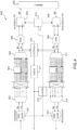
- FIG. 3 shows a diagram of a reflectometry and data transmission system based on an OMTDR type signal.
- the system described in picture 3 comprises a digital modulator 301, or a symbol encoder, for converting a sequence of binary data to be transmitted into complex digital symbols via modulation PSK phase modulation or QAM amplitude modulation.
- the digital complex signal thus formed is transmitted to a serial-parallel multiplexer 302 then to a pre-processing module 303 which performs Hermitian symmetry of the symbols and adds a guard time.
- the symbols are then transmitted to an inverse Fourier transform module 304.
- the symbols are purely real due to the preprocessing operation 303 carried out before the inverse Fourier transform 304.
- a demultiplexer 305 then makes it possible to serialize the real digital signal which is sent to a digital-analog converter 306 then to a coupler 307 to be injected into a transmission line.
- the system also includes a coupler 307 to measure the signal reflected at a point on the line.
- the measured signal undergoes the reverse operations to those carried out in transmission. It is digitized via an analog-to-digital converter 308, then multiplexed via a multiplexer 311.
- a direct Fourier transform module 312 converts the signal into the frequency domain, then a post-processing operation 313 reverses the pre-processing operation. processing 303 carried out on transmission, is applied.
- a demultiplexer 314 makes it possible to serialize the digital complex signal which is then demodulated via a digital demodulator 315 or a symbol decoder.
- the fault analysis is carried out on a real signal by carrying out a correlation 309 between the signal at the input of the digital-analog converter 306 and the signal at the output of the analog-digital converter 308.
- An analysis module 310 makes it possible to characterize the faults possible from the measured reflectogram.
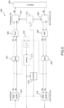
- FIG 4 represents an evolution of the system of picture 3 to which the principles of the invention described in the figure 2 .
- the invention applied to the system of the picture 3 thus consists in directly exploiting a complex signal at the output of the inverse Fourier transform module 304 instead of a real signal as is the case for the picture 3 .
- the pre-processing 303 and post-processing 313 modules used to render the real signal at the output of the IFFT module 304 are removed.
- the redundancy symbols inserted at the input of the module 304 can be removed .
- the complex correlation 210 is performed between the signal at the input of the converter 306 and the signal at the output of the converter 308.
- FIG 5 represents an alternative embodiment of the system described in figure 4 .
- a systolic implementation of the inverse 401 and direct 402 Fourier transform is used so that it is possible to eliminate the multiplexers and demultiplexers 302,305,311,314.
- the correlator 403 can be simplified by directly performing the inverse Fourier transform of the product of the signals taken respectively at the input of the IFFT module 401 and at the output of the FFT module 402.
- FIG. 6 also represents a diagram of a fault detection system according to another variant embodiment of the invention.
- the system 200 described in figure 2 is completed with a phase detector 602 and a phase corrector 603 which have the purpose of correcting the phase errors that the signal may undergo during its propagation in the cable and also of compensating for the phase shifts that may exist between the local oscillators associated with the IQ modulator 204 and the IQ demodulator 206.
- the phase of the signal can be changed during reception.
- a phase shift may also appear between the signal injected into the cable and the measured signal due to the respective frequency translation operations carried out on the injected signal and on the measured signal.
- the reflectometry signal transmitted in baseband is denoted x(t).
- a phase corrector 603 is then applied to the signal at the output of the analog-digital converter 207 before calculating a new reflectogram.
- phase detector 602 may incorporate a loop filter to smooth potential phase error variations and ensure system convergence.
- the phase corrector 603 can be realized by a simple complex multiplier.
- the corrected signal at the output of the phase corrector 603 can thus be correctly demodulated afterwards to recover the binary data transmitted via the signal.
- the various components of the system according to the invention can be implemented by means of software and/or hardware technology.
- the invention can be implemented totally or partially by means of an on-board processor or a specific device.
- the processor may be a generic processor, a specific processor, an application-specific integrated circuit (also known as an ASIC for "Application-Specific Integrated Circuit") or an array of field-programmable gates (also known as the English name of FPGA for “Field-Programmable Gate Array”).
- the system according to the invention can use one or more dedicated electronic circuits or a circuit for general use.
- the technique of the invention can be carried out on a reprogrammable calculation machine (a processor or a microcontroller for example) executing a program comprising a sequence of instructions, or on a dedicated calculation machine (for example a set of logic gates such as an FPGA or an ASIC, or any other hardware module).
- a reprogrammable calculation machine a processor or a microcontroller for example
- a dedicated calculation machine for example a set of logic gates such as an FPGA or an ASIC, or any other hardware module.
Description
L'invention concerne le domaine de l'analyse de défauts impactant des lignes de transmission, tels que des câbles électriques et plus particulièrement des câbles de communication.The invention relates to the field of the analysis of faults impacting transmission lines, such as electric cables and more particularly communication cables.
Plus précisément, l'invention concerne le domaine particulier de la réflectométrie appliquée au diagnostic filaire qui englobe le domaine de la détection, la localisation et la caractérisation de défauts dans des lignes de transmission simples ou des réseaux filaires complexes.More specifically, the invention relates to the particular field of reflectometry applied to wired diagnostics which encompasses the field of detection, location and characterization of faults in simple transmission lines or complex wired networks.
Les méthodes de réflectométrie connues fonctionnent selon le procédé suivant. Un signal de référence maitrisé, par exemple un signal impulsionnel ou encore un signal multi-porteuses, est injecté à une extrémité du câble à tester. Plus généralement, le signal de référence utilisé est choisi en fonction de ses propriétés d'intercorrélation. Le signal se propage le long du câble et se réfléchit sur les singularités qu'il comporte.Known reflectometry methods operate according to the following method. A controlled reference signal, for example a pulsed signal or even a multi-carrier signal, is injected at one end of the cable to be tested. More generally, the reference signal used is chosen according to its intercorrelation properties. The signal propagates along the cable and is reflected on the singularities it contains.
Une singularité dans un câble correspond à une rupture des conditions de propagation du signal dans ce câble. Elle résulte le plus souvent d'un défaut qui modifie localement l'impédance caractéristique du câble en provoquant une discontinuité dans ses paramètres linéiques. Un défaut peut résulter de tout type de dégradation locale d'un câble, d'un pincement, d'un frottement ou d'une dégradation superficielle de la gaine du câble.A singularity in a cable corresponds to a break in the signal propagation conditions in this cable. It most often results from a fault which locally modifies the characteristic impedance of the cable by causing a discontinuity in its linear parameters. A defect can result from any type of local degradation of a cable, pinching, rubbing or surface degradation of the cable sheath.
Le signal réfléchi est rétro-propagé jusqu'au point d'injection, puis est analysé par le système de réflectométrie. Le retard entre le signal injecté et le signal réfléchi permet de localiser une singularité, correspondant à un défaut électrique, dans le câble. Un défaut peut résulter d'un court circuit, d'un circuit ouvert ou encore d'une dégradation locale du câble voire d'un simple pincement du câble.The reflected signal is back-propagated to the injection point, then analyzed by the reflectometry system. The delay between the injected signal and the reflected signal makes it possible to locate a singularity, corresponding to an electrical fault, in the cable. A fault can result from a short circuit, an open circuit or even local degradation of the cable or even a simple pinching of the cable.
La réflectométrie est basée sur le principe d'une mesure d'un écho du signal injecté sur une singularité du câble analysé. Cependant, il existe des zones du câble, appelées zones aveugles, pour lesquelles un écho ne pourra pas être mesuré. Ces zones dépendent de la longueur d'onde du signal, donc de sa fréquence, de la vitesse de propagation du signal, de la fréquence d'échantillonnage du signal mesuré et de la distance entre le point d'injection du signal et le point où se situe la singularité. Si un défaut apparait dans une zone aveugle, il n'est donc pas possible de détecter sa présence en utilisant une méthode de réflectométrie classique.Reflectometry is based on the principle of measuring an echo of the signal injected on a singularity of the analyzed cable. However, there are areas of the cable, called blind areas, where an echo cannot be measured. These zones depend on the wavelength of the signal, therefore on its frequency, on the speed of propagation of the signal, on the sampling frequency of the measured signal and on the distance between the point of injection of the signal and the point where lies the singularity. If a defect appears in a blind zone, it is therefore not possible to detect its presence using a conventional reflectometry method.
Par ailleurs, la détection de défauts avec précision nécessite d'utiliser un signal à haute fréquence afin que la longueur d'onde du signal injecté coïncide avec les dimensions physiques des défauts dans le câble. Or, les convertisseurs analogiques-numériques qui permettent d'injecter et de mesurer un signal à haute fréquence sont couteux. En outre les canaux de transmission correspondant aux différentes technologies de câbles visées par les applications de réflectométrie, sont le plus souvent très sélectifs en fréquence et ne permettent donc pas une observation et un diagnostic large bande. Certaines bandes de fréquences peuvent être sensiblement atténuées ou perturbées ce qui peut rendre inexploitable le signal mesuré par le système de réflectométrie ou en tout cas complexifier l'identification des défauts éventuels.Furthermore, the detection of faults with precision requires the use of a high frequency signal so that the wavelength of the injected signal coincides with the physical dimensions of the faults in the cable. However, the analog-digital converters which make it possible to inject and measure a high-frequency signal are expensive. In addition, the transmission channels corresponding to the different cable technologies targeted by the reflectometry applications are most often very frequency selective and therefore do not allow broadband observation and diagnosis. Certain frequency bands can be significantly attenuated or disturbed, which can make the signal measured by the reflectometry system unusable or in any case complicate the identification of any faults.
Un autre problème concerne également la compatibilité d'un système de réflectométrie avec un câble ou un réseau de câbles de communication. Pour de tels câbles, le signal de réflectométrie injecté peut venir perturber les signaux de communication également transmis via ces câbles ce qui rend impossible un diagnostic pendant que le réseau de communication est en fonctionnement. Certaines bandes de fréquences ne peuvent pas être utilisées pour le diagnostic par réflectométrie car elles sont réservées à la transmission de données.Another problem also relates to the compatibility of a reflectometry system with a communication cable or network of cables. For such cables, the injected reflectometry signal can interfere with the communication signals also transmitted via these cables, which makes diagnosis impossible while the communication network is in operation. Certain frequency bands cannot be used for diagnosis by reflectometry because they are reserved for the transmission of data.
Les méthodes et systèmes de réflectométrie pour mesurer l'état de santé d'un câble et caractériser la présence d'éventuels défauts ont fait l'objet de nombreuses publications.Reflectometry methods and systems for measuring the state of health of a cable and characterizing the presence of any faults have been the subject of numerous publications.
Sans être exhaustif, on peut citer les demandes de brevet internationales
Ces systèmes ne résolvent pas les problèmes précités car ils fonctionnent le plus souvent à fréquence fixe, ne permettent pas d'identifier des défauts présents dans une zone aveugle ni de faire fonctionner le système de réflectométrie sur un réseau de câbles de communication en fonctionnement sans perturber les communications.These systems do not solve the aforementioned problems because they most often operate at a fixed frequency, do not make it possible to identify faults present in a blind zone or to operate the reflectometry system on a network of communication cables in operation without disturbing the communications.
On connait par ailleurs les solutions décrites dans les documents
L'invention permet de résoudre le problème des zones aveugles en utilisant un signal de réflectométrie complexe modulé en quadrature et en exploitant conjointement les réflectogrammes obtenus pour la voie réelle et la voie imaginaire du signal mesuré.The invention makes it possible to solve the problem of blind zones by using a complex reflectometry signal modulated in quadrature and by jointly exploiting the reflectograms obtained for the real channel and the imaginary channel of the measured signal.
L'invention permet également de réaliser une analyse fréquentielle large bande d'un câble par l'utilisation d'une transposition en fréquence du signal injecté dans le câble.The invention also makes it possible to carry out a broadband frequency analysis of a cable by using a frequency transposition of the signal injected into the cable.
L'utilisation d'un signal complexe permet aussi un fonctionnement simultané d'une communication de données via le câble à analyser et d'une analyse des défauts du câble par réflectométrie avec un débit de transmission de données doublé par rapport à un signal réel.The use of a complex signal also allows simultaneous operation of data communication via the cable to be analyzed and analysis of cable faults by reflectometry with a data transmission rate doubled compared to a real signal.
L'invention a ainsi pour objet un système de réflectométrie pour l'analyse de défauts dans une ligne de transmission dans laquelle un signal complexe généré puis modulé a été injecté, ledit système comprenant :
- un moyen de mesure du signal complexe modulé se propageant dans la ligne de transmission,
- un démodulateur du signal mesuré apte à produire un signal complexe démodulé,
- un corrélateur complexe configuré pour corréler le signal complexe démodulé avec une copie du signal complexe généré, pour produire un premier réflectogramme temporel correspondant à la partie réelle de la corrélation complexe et un second réflectogramme temporel correspondant à la partie imaginaire de la corrélation complexe,
- un module d'analyse conjointe du premier réflectogramme temporel et du second réflectogramme temporel pour identifier la présence de défauts dans la ligne de transmission.
- a means for measuring the modulated complex signal propagating in the transmission line,
- a measured signal demodulator capable of producing a demodulated complex signal,
- a complex correlator configured to correlate the demodulated complex signal with a copy of the generated complex signal, to produce a first time domain reflectogram corresponding to the real part of the complex correlation and a second time domain reflectogram corresponding to the imaginary part of the complex correlation,
- a joint analysis module of the first time reflectogram and of the second time reflectogram to identify the presence of faults in the transmission line.
Selon un aspect particulier de l'invention, le module d'analyse est configuré pour déterminer un réflectogramme temporel unique à partir du module de la corrélation complexe.According to a particular aspect of the invention, the analysis module is configured to determine a unique temporal reflectogram from the module of the complex correlation.
Selon une variante de réalisation, le système selon l'invention comprend en outre un détecteur de phase configuré pour mesurer la phase de la corrélation complexe à l'abscisse temporelle 0 et un correcteur de phase configuré pour corriger le signal complexe démodulé de la phase mesurée par le détecteur de phase.According to a variant embodiment, the system according to the invention further comprises a phase detector configured to measure the phase of the complex correlation at the
Selon une variante de réalisation, le système selon l'invention comprend en outre un générateur de signal complexe, un modulateur apte à moduler le signal complexe pour produire un signal modulé et un moyen pour injecter le signal modulé en un point de la ligne de transmission.According to a variant embodiment, the system according to the invention further comprises a complex signal generator, a modulator capable of modulating the complex signal to produce a modulated signal and means for injecting the modulated signal at a point on the transmission line. .
Selon une variante de réalisation, le système selon l'invention comprend en outre :
- un oscillateur local apte à contrôler la fréquence du modulateur pour réaliser une transposition en fréquence du signal et un oscillateur local apte à contrôler la fréquence du démodulateur pour réaliser une transposition du signal en bande de base,
- un organe de contrôle apte à contrôler la valeur de la fréquence à laquelle le signal est transposé.
- a local oscillator capable of controlling the frequency of the modulator to perform a frequency transposition of the signal and a local oscillator capable of controlling the frequency of the demodulator to perform a transposition of the signal into baseband,
- a control member able to control the value of the frequency at which the signal is transposed.
Selon un aspect particulier de l'invention, l'organe de contrôle est configuré pour déterminer la valeur de la fréquence de transposition du signal en fonction d'au moins une analyse du premier réflectogramme temporel et/ou du second réflectogramme temporel.According to a particular aspect of the invention, the control unit is configured to determine the value of the transposition frequency of the signal as a function of at least one analysis of the first time reflectogram and/or of the second time reflectogram.
Selon un aspect particulier de l'invention, l'analyse du premier réflectogramme temporel et/ou du second réflectogramme temporel porte sur une mesure de l'atténuation du signal mesuré.According to a particular aspect of the invention, the analysis of the first temporal reflectogram and/or of the second temporal reflectogram relates to a measurement of the attenuation of the measured signal.
Selon un aspect particulier de l'invention, le signal complexe généré est un signal fréquentiel à multi-porteuses, ledit système comprenant en outre à cet effet un module de transformée de Fourier inverse appliqué au signal complexe généré et un module de transformée de Fourier appliqué au signal complexe démodulé.According to a particular aspect of the invention, the generated complex signal is a multi-carrier frequency signal, said system further comprising for this purpose an inverse Fourier transform module applied to the generated complex signal and a Fourier transform module applied to the demodulated complex signal.
Selon un aspect particulier de l'invention, le corrélateur complexe comprend un corrélateur du signal fréquentiel généré avec le signal fréquentiel démodulé et une transformée de Fourier inverse appliquée au résultat de la corrélation.According to a particular aspect of the invention, the complex correlator comprises a correlator of the frequency signal generated with the demodulated frequency signal and an inverse Fourier transform applied to the result of the correlation.
Selon un aspect particulier de l'invention, le générateur de signal complexe comprend une interface pour recevoir des données numériques à transmettre et un modulateur pour convertir les données numériques en symboles complexes, ledit système comprenant en outre un récepteur pour convertir le signal démodulé complexe en données numériques reçues.According to a particular aspect of the invention, the complex signal generator comprises an interface for receiving digital data to be transmitted and a modulator for converting the digital data into complex symbols, said system further comprising a receiver for converting the complex demodulated signal into digital data received.
Selon une variante de réalisation, le système selon l'invention comprend en outre un encodeur des données numériques à transmettre et un décodeur des données numériques reçues, l'organe de contrôle étant configuré pour déterminer le taux de codage de l'encodeur et du décodeur.According to a variant embodiment, the system according to the invention further comprises an encoder for the digital data to be transmitted and a decoder for the digital data received, the control unit being configured to determine the coding rate of the encoder and of the decoder .
Selon une variante de réalisation, le système selon l'invention comprend en outre un module de calcul du taux d'erreurs entre les données numériques décodées et les données numériques à transmettre, l'organe de contrôle étant configuré pour déterminer la valeur de la fréquence de transposition du signal et/ou le taux de codage en fonction d'au moins le taux d'erreurs calculé.According to a variant embodiment, the system according to the invention further comprises a module for calculating the rate of errors between the decoded digital data and the digital data to be transmitted, the control member being configured to determine the value of the frequency transposition of the signal and/or the coding rate as a function of at least the calculated error rate.
D'autres caractéristiques et avantages de la présente invention apparaîtront mieux à la lecture de la description qui suit en relation aux dessins annexés qui représentent :
- La
figure 1 , un schéma d'un système de détection de défauts dans une ligne de transmission selon l'art antérieur, - La
figure 2 , un schéma d'un système de détection de défauts dans une ligne de transmission selon l'invention, - La
figure 2 bis, deux exemples de réflectogrammes illustrant l'apport de l'utilisation d'un signal de réflectométrie complexe, - La
figure 3 , un schéma d'un système de détection de défauts utilisant un signal de type OMTDR, - La
figure 4 , un schéma d'un système de détection de défauts dans une ligne de transmission selon un mode particulier de l'invention, - La
figure 5 , le schéma de lafigure 4 dans lequel le module de corrélation est explicité, - La
figure 6 , un schéma d'un système de détection de défauts selon une variante de réalisation de l'invention.
- There
figure 1 , a diagram of a fault detection system in a transmission line according to the prior art, - There
picture 2 - There
picture 2 bis, two examples of reflectograms illustrating the contribution of the use of a complex reflectometry signal, - There
picture 3 - There
figure 4 , a diagram of a system for detecting faults in a transmission line according to a particular mode of the invention, - There
figure 5 , the diagram of thefigure 4 in which the correlation module is explained, - There
figure 6 , a diagram of a fault detection system according to a variant embodiment of the invention.
La
Le système 100 comporte principalement un générateur 102 d'un signal de référence à partir des paramètres 101 du signal. Le signal de référence peut être temporel ou fréquentiel. Il peut s'agir d'une simple impulsion temporelle ou d'un signal plus élaboré dans la mesure où celui-ci présente de bonnes propriétés d'autocorrélation, c'est-à-dire que le résultat d'un calcul d'autocorrélation appliqué à ce signal donne un pic d'amplitude significatif qu'il est possible d'identifier et de détecter. Par exemple, le signal utilisé peut être du type OMTDR (Orthogonal Multi-tone Time Domain Reflectometry) ou MCTDR (MultiCarrier Time Domain Reflectometry). Un convertisseur numérique-analogique 103 permet de convertir le signal numérique en un signal analogique qui est ensuite injecté en un point de la ligne de transmission (non représentée à la
Le système 100 comporte ensuite une partie mesure qui comprend un coupleur 104 (identique au précédent ou distinct) pour mesurer, en un point de la ligne, le signal réfléchi et rétro-propagé dans la ligne de transmission. Le signal analogique mesuré est converti numériquement via un convertisseur analogique numérique 105. Le signal numérique peut être filtré 106 ou moyenné afin de limiter l'influence du bruit de mesure, puis un corrélateur 107 est en charge de réaliser une corrélation entre le signal mesuré et le signal généré, pour différents décalages temporels, afin de produire un réflectogramme temporel. Un exemple de réflectogramme temporel est donné sur le bas de la
Sur la droite de la
Un objectif de l'invention est de proposer un système qui soit plus flexible au niveau du paramétrage de l'occupation spectrale du signal de réflectométrie injecté dans le câble à analyser. D'une part, un fonctionnement à haute fréquence permet de mieux caractériser des défauts de petite taille et d'autre part, certaines bandes de fréquences peuvent être perturbées par des interférences, atténuées du fait de la sélectivité en fréquence de la réponse fréquentielle du câble ou encore réservées à d'autres applications (par exemple pour la communication de données).One objective of the invention is to propose a system which is more flexible in terms of parameterizing the spectral occupancy of the reflectometry signal injected into the cable to be analyzed. On the one hand, high frequency operation allows better characterization of small defects and on the other hand, certain frequency bands can be disturbed by interference, attenuated due to the frequency selectivity of the frequency response of the cable. or even reserved for other applications (for example for data communication).
A cet effet, le système 200 schématisé à la
Une mesure du signal rétro-propagé dans la ligne de transmission est réalisée en captant le signal via le même coupleur 205 ou un second coupleur différent du premier coupleur 205 puis est fourni en entrée d'un démodulateur IQ 206 qui réalise une démodulation de phase du signal pour produire deux signaux analogiques correspondants respectivement à une voie en phase I et une voie en quadrature de phase Q. Les deux signaux sont ensuite numérisés via un convertisseur analogique-numérique 207.A measurement of the back-propagated signal in the transmission line is carried out by picking up the signal via the
Le système 200 comprend également un corrélateur 210 complexe pour réaliser une corrélation, à différents instants temporels, entre le signal complexe mesuré en sortie du convertisseur analogique numérique 207 et le signal complexe généré en entrée du convertisseur numérique analogique 203. Ainsi, le corrélateur 210 fournit deux réflectogrammes distincts, un premier réflectogramme correspondant à la voie réelle (I) du signal complexe et un second réflectogramme correspondant à la voie imaginaire (Q) du signal complexe. Autrement dit, le premier réflectogramme correspond à la partie réelle de la corrélation complexe tandis que le second réflectogramme correspond à la partie imaginaire de la corrélation complexe. Les deux réflectogrammes sont exploités par un module d'analyse 211 pour détecter et caractériser la présence de défauts éventuels.The
L'utilisation d'un signal complexe associée à l'exploitation de deux réflectogrammes distincts permet d'améliorer la détection de défauts notamment en résolvant le problème des zones aveugles.The use of a complex signal associated with the exploitation of two distinct reflectograms makes it possible to improve the detection of defects in particular by solving the problem of blind zones.
Comme expliqué précédemment, il existe des zones qu'on appelle zones aveugles, correspondant à certaines valeurs de distance entre le point d'injection du signal et le défaut, pour lesquelles l'écho du signal sur le défaut n'est pas détecté. Ce problème est bien connu dans le domaine de la réflectométrie et dépend de différents paramètres dont la longueur du câble, la longueur d'onde du signal, sa fréquence d'échantillonnage et la vitesse de propagation de l'onde dans le câble.As explained previously, there are zones called blind zones, corresponding to certain values of distance between the point of injection of the signal and the fault, for which the echo of the signal on the fault is not detected. This problem is well known in the field of reflectometry and depends on various parameters including the length of the cable, the wavelength of the signal, its sampling frequency and the speed of propagation of the wave in the cable.
Ainsi, les systèmes usuels de réflectométrie tels que celui décrit à la
Lorsqu'on utilise un signal complexe, tel que proposé via le système de la
Ce principe est illustré sur la
Sur chacun des deux réflectogrammes, on peut observer que pour certaines valeurs de la distance entre le défaut et le point d'injection du signal, aucun pic d'amplitude n'est observé dans le réflectogramme. Ce phénomène se reproduit périodiquement lorsqu'on fait varier la position du défaut le long du câble. Les zones pour lesquelles aucun pic n'est observé dans le réflectogramme correspondent aux zones dites aveugles.On each of the two reflectograms, it can be observed that for certain values of the distance between the defect and the signal injection point, no amplitude peak is observed in the reflectogram. This phenomenon is reproduced periodically when the position of the fault along the cable is varied. The zones for which no peak is observed in the reflectogram correspond to the so-called blind zones.
Cependant, on remarque également que les zones aveugles ne sont pas situées aux mêmes positions pour le réflectogramme correspondant à la partie réelle du signal et pour le réflectogramme correspondant à la partie imaginaire du signal.However, it is also noted that the blind areas are not located at the same positions for the reflectogram corresponding to the real part of the signal and for the reflectogram corresponding to the imaginary part of the signal.
Ainsi, en exploitant les deux réflectogrammes, il n'existe aucune position de défaut pour laquelle il n'est pas possible d'identifier un pic d'amplitude dans au moins un des deux réflectogrammes.Thus, by using the two reflectograms, there is no fault position for which it is not possible to identify an amplitude peak in at least one of the two reflectograms.
L'analyse 211 des deux réflectogrammes peut consister à observer séparément les deux réflectogrammes, par exemple en fixant un seuil de détection pour chaque réflectogramme et en retenant les pics d'amplitude observés, qui dépassent ce seuil, dans l'un ou l'autre des deux réflectogrammes.The
L'analyse 211 peut également consister à calculer un unique réflectogramme à partir des deux réflectogrammes fournis par le corrélateur 210, par exemple en calculant le module de la corrélation complexe ou le module au carré de la corrélation complexe. Ainsi, un pic d'amplitude correspondant à un défaut sera présent dans le module de la corrélation complexe quelle que soit la position du défaut.The
Sur le schéma de la
Dans une variante de réalisation non représentée à la
Le module d'analyse 211 peut restituer les résultats d'analyse à un utilisateur via une interface homme machine (non représentée), par exemple un écran ou toute autre interface. Les résultats d'analyse peuvent consister à fournir le ou les réflectogramme(s) calculé(s) ou à fournir directement la ou les position(s) du ou des défaut(s) identifié(s) ainsi que toute autre information concernant les défauts détectés.The
Selon un mode de réalisation particulier de l'invention, le système 200 comporte également un organe de contrôle 212 couplé à un oscillateur local 213 qui agit sur le modulateur 204 pour réaliser une transposition du signal en fréquence avant son injection dans le câble. Réciproquement, l'oscillateur local 213 agit également sur le démodulateur 206 pour ramener le signal en bande de base après son acquisition. Bien qu'on ait représenté un seul oscillateur local 213 sur la
L'organe de contrôle 212 pilote l'oscillateur local en lui communiquant la valeur de la fréquence de transposition du signal.The
Un avantage de ce mode de réalisation de l'invention est qu'il permet de transposer le signal dans les hautes fréquences du canal de propagation associé au câble à analyser. Un signal à haute fréquence présente une longueur d'onde faible qui permet de mieux caractériser les défauts de petite taille. Par ailleurs, l'organe de contrôle 212 peut déterminer la fréquence de transposition en fonction de différents paramètres.An advantage of this embodiment of the invention is that it makes it possible to transpose the signal into the high frequencies of the propagation channel associated with the cable to be analyzed. A high-frequency signal has a short wavelength which makes it possible to better characterize small defects. Furthermore, the
La fréquence de transposition peut être sélectionnée de sorte à placer le signal dans une bande de fréquence autorisée pour l'analyse de défauts et à éviter toute bande de fréquence interdite car réservée à d'autres applications.The transposition frequency can be selected so as to place the signal in an authorized frequency band for fault analysis and to avoid any prohibited frequency band because it is reserved for other applications.
La fréquence de transposition peut aussi être sélectionnée de sorte à choisir la bande de fréquence du signal en fonction des paramètres du câble à analyser. En effet, la bande de fréquence d'un câble est généralement très sélective en fréquence et le choix de la fréquence du signal a un impact direct sur le réflectogramme mesuré et donc sur la précision de la caractérisation des défauts. Il est donc important de pouvoir optimiser la bande de fréquence du signal et de pouvoir la faire varier dynamiquement en fonction du type de câble analysé.The transposition frequency can also be selected so as to choose the frequency band of the signal according to the parameters of the cable to be analyzed. Indeed, the frequency band of a cable is generally very frequency selective and the choice of signal frequency has a direct impact on the measured reflectogram and therefore on the accuracy of the characterization of faults. It is therefore important to be able to optimize the frequency band of the signal and to be able to vary it dynamically according to the type of cable analyzed.
L'organe de contrôle 212 peut également déterminer la fréquence de transposition en fonction d'une analyse du réflectogramme fourni par le corrélateur 210. Plus précisément, l'organe de contrôle 212 peut analyser le niveau d'atténuation du signal sur le réflectogramme et en déduire une information sur le niveau de puissance du signal mesuré dans la bande de fréquence courante. Si le niveau de puissance est trop faible, cela signifie que la bande de fréquence sélectionnée est trop atténuée, dans ce cas l'organe de contrôle 212 peut sélectionner une autre bande de fréquence et donc une nouvelle fréquence de transposition.The
D'autres critères d'analyse peuvent être utilisés en exploitant le réflectogramme pour, par exemple, déterminer si la bande de fréquence du signal est perturbée par des interférences ou si plus généralement le réflectogramme n'est pas exploitable et nécessite un changement de bande de fréquence. Ainsi, l'organe de contrôle peut modifier dynamiquement la fréquence de transposition si la bande de fréquence courante du signal est perturbée.Other analysis criteria can be used by exploiting the reflectogram to, for example, determine if the frequency band of the signal is disturbed by interference or if more generally the reflectogram is not usable and requires a change of band of frequency. Thus, the control unit can dynamically modify the transposition frequency if the current frequency band of the signal is disturbed.
Le système 200 comprenant l'organe de contrôle 212 peut également être utilisé pour réaliser une reconstruction large bande en effectuant un balayage successif de toute la bande de fréquence du câble par sous-bandes. De cette manière, plusieurs réflectogrammes associés à plusieurs sous-bandes fréquentielles peuvent être déterminés et un réflectogramme global associé à la bande de fréquence totale du câble peut être obtenu in fine.The
Selon un autre mode de réalisation de l'invention, le système 200 peut également comporter une partie 201,202 d'émission de données ainsi qu'une partie 208,209 de réception de données La transmission de données se fait via le signal de réflectométrie, permettant ainsi de concevoir un système 200 qui fonctionne à la fois en tant que système de communication et en tant que système d'analyse de défauts par réflectométrie ou par transférométrie. Un avantage de ce mode de réalisation est qu'il permet de faire fonctionner les deux systèmes simultanément sans qu'ils se perturbent réciproquement ou interfèrent l'un avec l'autre.According to another embodiment of the invention, the
La partie émission du système comporte un générateur de données numériques 201 ou plus généralement une interface pour recevoir des données numériques depuis une application de communication. Elle comporte en outre un modulateur numérique 202 apte à convertir les données binaires en symboles complexes afin de fournir un signal numérique complexe au convertisseur 203. Le modulateur numérique 202 peut être un modulateur de phase PSK (Phase Shift Keying) ou un modulateur d'amplitude QAM (Quadrature Amplitude Modulation) ou tout autre modulateur ou codeur de symboles apte à convertir une séquence de bits en symboles numériques complexes appartenant à une constellation de symboles donnée.The transmission part of the system comprises a
Optionnellement, le modulateur numérique 202 peut aussi comporter un codeur canal ou codeur correcteur ou encodeur de données numériques qui vise à ajouter de la redondance aux bits à émettre afin de les protéger contre d'éventuelles perturbations causant des erreurs de transmission dans le canal de propagation.Optionally, the
La partie réception du système comporte un démodulateur numérique 208 qui effectue la conversion des symboles complexes du signal mesuré en bits ainsi qu'un récepteur de données 209 qui transmet les bits démodulés vers l'application destinatrice des données. Optionnellement, le démodulateur numérique 208 comporte un décodeur pour décoder les bits démodulés s'ils ont été codés en émission. Le démodulateur numérique 208 peut également comprendre un module de calcul du taux d'erreurs sur les symboles ou sur les bits reçus par comparaison avec les symboles ou les bits émis ou par un mécanisme intégré au décodeur.The reception part of the system comprises a
L'organe de contrôle 212 peut être configuré pour sélectionner le type de modulation/démodulation numérique et/ou le type de codage/décodage des bits. En particulier l'organe de contrôle 212 peut déterminer le meilleur taux de codage à appliquer aux bits à transmettre en fonction de l'analyse du réflectogramme qui donne une indication sur l'état du canal de transmission.The
L'organe de contrôle 212 peut aussi utiliser l'information de taux d'erreurs calculée par le décodeur pour déterminer les paramètres du codeur et du décodeur mais aussi pour sélectionner la fréquence de transposition. En effet, le taux d'erreurs donne une information sur le niveau de perturbation dans une bande de fréquence donnée. Ainsi, si le taux d'erreurs est trop élevé, par exemple supérieur à un seuil donné, l'organe de contrôle peut décider de sélectionner une autre bande de fréquence pour le signal.The
Le système 200 selon ce mode de réalisation adapté à la communication peut permettre plusieurs communications simultanées sur différentes bandes de fréquences, en choisissant une fréquence de transposition différente pour chaque système dans le cas d'un réseau de câbles de communication comprenant plusieurs systèmes de communication 200 connectés à différents points du réseau. Ce cas de figure correspond à une application de transférométrie.The
On décrit à présent un exemple particulier de réalisation du système selon l'invention associé à un signal de réflectométrie et de communication fréquentiel à multi-porteuses du type OFDM (Orthogonal Frequency Division Multiplexing). Cette technologie a notamment servi de base à l'élaboration de signaux particuliers utilisés en réflectométrie du type OMTDR (Orthogonal Multi-tone Time Domain Reflectometry) ou MCTDR (MultiCarrier Time Domain Reflectometry).We will now describe a particular embodiment of the system according to the invention associated with a multi-carrier frequency reflectometry and communication signal of the OFDM (Orthogonal Frequency Division Multiplexing) type. This technology has notably served as a basis for the development of specific signals used in reflectometry of the OMTDR (Orthogonal Multi-tone Time Domain Reflectometry) or MCTDR (MultiCarrier Time Domain Reflectometry) type.
La
Le système décrit à la
Le système comporte également un coupleur 307 pour mesurer le signal réfléchi en un point de la ligne. Le signal mesuré subit les opérations inverses à celles effectuées en émission. Il est numérisé via un convertisseur analogique-numérique 308, puis multiplexé via un multiplexeur 311. Un module de transformée de Fourier directe 312 converti le signal dans le domaine fréquentiel, puis une opération de post-traitement 313 inverse de l'opération de pré-traitement 303 réalisée à l'émission, est appliquée. Un démultiplexeur 314 permet de sérialiser le signal complexe numérique qui est ensuite démodulé via un démodulateur numérique 315 ou un décodeur de symboles.The system also includes a
L'analyse de défauts est effectuée sur un signal réel en réalisant une corrélation 309 entre le signal en entrée du convertisseur numérique-analogique 306 et le signal en sortie du convertisseur analogique-numérique 308. Un module d'analyse 310 permet de caractériser les défauts éventuels à partir du réflectogramme mesuré.The fault analysis is carried out on a real signal by carrying out a
La
Les éléments communs entre le système 400 de la
L'invention appliquée au système de la ![]()
![]()
La
En outre, le corrélateur 403 peut être simplifié en effectuant directement la transformée de Fourier inverse du produit des signaux prélevés respectivement en entrée du module IFFT 401 et en sortie du module FFT 402.Furthermore, the
La
Selon cette variante, le système 200 décrit à la
Le signal de réflectométrie transmis en bande de base est noté x(t). Le signal en sortie du modulateur IQ 204 réalisant une translation de fréquence vers la fréquence f0 est noté ![]()
![]()
![]()
![]()
Le signal xrf(t) est démodulé en sortie du démodulateur IQ 206. Si l'erreur de phase entre le modulateur 204 et le démodulateur 206 est égale à ϕ0, et, en négligeant l'atténuation du canal entre transmetteur et récepteur, le signal en bande de base reçu est défini comme: ![]()
Le réflectogramme est obtenu à partir de la corrélation entre le signal reçu x'(t) et filtré et le signal injecté x(t), en calculant la corrélation complexe c(t) : ![]()
![]()
The reflectogram is obtained from the correlation between the filtered received signal x'(t) and the injected signal x(t), by calculating the complex correlation c(t):![]()
L'erreur de phase peut ainsi être directement extraite de la valeur c(t=0) du réflectogramme car pour t=0 le résultat de l'intégrale ![]()
![]()
Ainsi, le système 600 décrit à la
Selon une variante, le détecteur de phase 602 peut intégrer un filtre de boucle afin de lisser les variations potentielles de l'erreur de phase et d'assurer une convergence du système.Alternatively,
Le correcteur de phase 603 peut être réalisé par un simple multiplieur complexe.The
Le signal corrigé en sortie du correcteur de phase 603 peut ainsi être correctement démodulé ensuite pour récupérer les données binaires transmises via le signal.The corrected signal at the output of the
Les différents composants du système selon l'invention peuvent être mis en oeuvre au moyen de technologie logicielle et/ou matérielle. En particulier, l'invention peut être implémentée totalement ou partiellement au moyen d'un processeur embarqué ou d'un dispositif spécifique. Le processeur peut être un processeur générique, un processeur spécifique, un circuit intégré propre à une application (connu aussi sous le nom anglais d'ASIC pour « Application-Specific Integrated Circuit ») ou un réseau de portes programmables in situ (connu aussi sous le nom anglais de FPGA pour « Field-Programmable Gate Array »). Le système selon l'invention peut utiliser un ou plusieurs circuits électroniques dédiés ou un circuit à usage général. La technique de l'invention peut se réaliser sur une machine de calcul reprogrammable (un processeur ou un micro contrôleur par exemple) exécutant un programme comprenant une séquence d'instructions, ou sur une machine de calcul dédiée (par exemple un ensemble de portes logiques comme un FPGA ou un ASIC, ou tout autre module matériel).The various components of the system according to the invention can be implemented by means of software and/or hardware technology. In particular, the invention can be implemented totally or partially by means of an on-board processor or a specific device. The processor may be a generic processor, a specific processor, an application-specific integrated circuit (also known as an ASIC for "Application-Specific Integrated Circuit") or an array of field-programmable gates (also known as the English name of FPGA for “Field-Programmable Gate Array”). The system according to the invention can use one or more dedicated electronic circuits or a circuit for general use. The technique of the invention can be carried out on a reprogrammable calculation machine (a processor or a microcontroller for example) executing a program comprising a sequence of instructions, or on a dedicated calculation machine (for example a set of logic gates such as an FPGA or an ASIC, or any other hardware module).
Claims (12)
- A reflectometry system (200,400,600) for the analysis of faults in a transmission line into which a complex signal, generated then modulated, has been injected, said system comprising:- a means (205) for measuring the modulated complex signal propagating in the transmission line,- a demodulator (206) of the measured signal able to produce a demodulated complex signal,- a complex correlator (210,403) configured for correlating the demodulated complex signal with a copy of the generated complex signal, in order to produce a first time-domain reflectogram corresponding to the real part of the complex correlation and a second time-domain reflectogram corresponding to the imaginary part of the complex correlation,- a module for joint analysis (211) of the first time-domain reflectogram and of the second time-domain reflectogram for identifying the presence of faults in the transmission line.
- The reflectometry system (200,400,600) according to claim 1, wherein the analysis module (211) is configured for determining a single time-domain reflectogram from the complex correlation module.
- The reflectometry system (600) according to one of the preceding claims, further comprising a phase detector (602) configured for measuring the phase of the complex correlation at the 0 of the time abscissa and a phase corrector (603) configured for correcting the demodulated complex signal of the phase measured by the phase detector (602).
- The reflectometry system (200,400,600) according to one of the preceding claims, further comprising a complex signal generator (201,202), a modulator (204) able to modulate the complex signal for producing a modulated signal and a means (205) for injecting the modulated signal at one point of the transmission line.
- The reflectometry system (200,400,600) according to claim 4, further comprising:- a local oscillator (213) able to control the frequency of the modulator (204) for performing a frequency transposition of the signal and a local oscillator (213) able to control the frequency of the demodulator (206) for performing a transposition of the signal into baseband,- a control mechanism (212) able to control the value of a transposition frequency at which the signal is transposed.
- The reflectometry system (200,400,600) according to claim 5, wherein the control mechanism (212) is configured for determining the value of the transposition frequency of the signal as a function of at least one analysis of the first time-domain reflectogram and/or of the second time-domain reflectogram.
- The reflectometry system (200,400,600) according to claim 6, wherein the analysis of the first time-domain reflectogram and/or of the second time-domain reflectogram relates to a measurement of the attenuation level of the measured signal.
- The reflectometry system (400) according to one of claims 4 to 7, wherein the generated complex signal is a multi-carrier frequency-domain signal, said system further comprising, for this purpose, an inverse Fourier transform module (304,401) applied to the generated complex signal and a Fourier transform module (312,402) applied to the demodulated complex signal for generating a demodulated frequency-domain signal.
- The reflectometry system (400) according to claim 8, wherein the complex correlator (403) comprises a correlator of the frequency-domain signal generated with the demodulated frequency-domain signal and an inverse Fourier transform applied to the result of the correlation.
- The reflectometry system according to one of claims 4 to 9, wherein the complex signal generator comprises an interface (201) for receiving digital data to be transmitted and a modulator (202,301) for converting the digital data into complex symbols, said system further comprising a receiver (208,315) for converting the complex demodulated signal into received digital data.
- The reflectometry system (200) according to claim 10, further comprising an encoder (202) of the digital data to be transmitted and a decoder (208) of the received digital data, the control mechanism (212) being configured for determining the coding rate of the encoder and of the decoder.
- The reflectometry system (200) according to claim 11, further comprising a module for calculating the error rate between the decoded digital data and the digital data to be transmitted, the control mechanism (212) being configured for determining the value of the transposition frequency of the signal and/or the coding rate as a function of at least the calculated error rate.
Applications Claiming Priority (2)
| Application Number | Priority Date | Filing Date | Title |
|---|---|---|---|
| FR1662308A FR3060128B1 (en) | 2016-12-12 | 2016-12-12 | SYSTEM AND METHOD FOR DETECTING DEFECTS IN A TRANSMISSION LINE USING A COMPLEX SIGNAL |
| PCT/EP2017/080767 WO2018108526A1 (en) | 2016-12-12 | 2017-11-29 | System for detecting faults in a transmission line by using a complex signal |
Publications (2)
| Publication Number | Publication Date |
|---|---|
| EP3552032A1 EP3552032A1 (en) | 2019-10-16 |
| EP3552032B1 true EP3552032B1 (en) | 2023-03-29 |
Family
ID=57909752
Family Applications (1)
| Application Number | Title | Priority Date | Filing Date |
|---|---|---|---|
| EP17804207.3A Active EP3552032B1 (en) | 2016-12-12 | 2017-11-29 | System for detecting faults in a transmission line by using a complex signal |
Country Status (4)
| Country | Link |
|---|---|
| US (1) | US11156652B2 (en) |
| EP (1) | EP3552032B1 (en) |
| FR (1) | FR3060128B1 (en) |
| WO (1) | WO2018108526A1 (en) |
Families Citing this family (7)
| Publication number | Priority date | Publication date | Assignee | Title |
|---|---|---|---|---|
| FR3082947B1 (en) | 2018-06-26 | 2020-06-12 | Commissariat A L'energie Atomique Et Aux Energies Alternatives | METHOD FOR CHARACTERIZING A DEFECT IN A NETWORK OF UNKNOWN TOPOLOGY TRANSMISSION LINES |
| FR3083323B1 (en) * | 2018-06-29 | 2020-06-19 | Commissariat A L'energie Atomique Et Aux Energies Alternatives | METHOD AND SYSTEM FOR CHARACTERIZING A DEFECT IN A NETWORK OF TRANSMISSION LINES, BY TIME REVERSAL |
| FR3093811B1 (en) | 2019-03-15 | 2021-05-14 | Safran Electrical & Power | Arc detection by reflectometry |
| CN110118912B (en) * | 2019-04-23 | 2022-02-01 | 武汉理工大学 | Grey correlation analysis-based single-phase earth fault line selection method for arc suppression coil device-grounded power distribution network |
| US11533105B1 (en) * | 2020-06-01 | 2022-12-20 | Cable Television Laboratories, Inc. | Systems and methods for determining reflection and transmission coefficients |
| US11609258B2 (en) * | 2020-11-27 | 2023-03-21 | Uif (University Industry Foundation), Yonsei University | Apparatus and method for detecting cable fault based on reflectometry using AI |
| FR3136859A1 (en) * | 2022-06-21 | 2023-12-22 | Commissariat A L'energie Atomique Et Aux Energies Alternatives | Method for detecting and locating direct or termination faults for a cable made up of several sections of inhomogeneous cables |
Family Cites Families (8)
| Publication number | Priority date | Publication date | Assignee | Title |
|---|---|---|---|---|
| US4630228A (en) * | 1982-06-28 | 1986-12-16 | Systron-Donner Corporation | Transmission line analyzer for automatically identifying the severities and locations of multiple mismatches |
| FR2931323A1 (en) * | 2008-05-14 | 2009-11-20 | Commissariat Energie Atomique | MULTI-PORTABLE REFLECTOMETRY DEVICE AND METHOD FOR ONLINE DIAGNOSIS OF AT LEAST ONE TRANSMISSION LINE |
| FR2937146B1 (en) * | 2008-10-15 | 2011-02-11 | Commissariat Energie Atomique | DEVICE AND METHOD FOR DISTRIBUTED REFLECTOMETRY FOR DIAGNOSING A TRANSMISSION NETWORK |
| US9244117B2 (en) | 2013-03-15 | 2016-01-26 | Livewire Innovation, Inc. | Systems and methods for implementing S/SSTDR measurements |
| FR3006769B1 (en) * | 2013-06-11 | 2016-12-02 | Commissariat Energie Atomique | REFLECTOMETRY METHOD FOR IDENTIFYING NON-FREE IMPACTS OF A CABLE |
| FR3012617A1 (en) * | 2013-10-31 | 2015-05-01 | Commissariat Energie Atomique | METHOD OF LOCATING ELECTRICAL FAULTS WITHIN A NETWORK OF TRANSMISSION LINES AND SYSTEM THEREFOR |
| FR3012616B1 (en) * | 2013-10-31 | 2019-05-31 | Commissariat A L'energie Atomique Et Aux Energies Alternatives | METHOD FOR GENERATING A MULTI-CARRIER REFLECTOMETRY SIGNAL FOR IMPLEMENTATION IN A DISTRIBUTED SYSTEM |
| FR3019307B1 (en) | 2014-03-26 | 2016-03-18 | Labinal Power Systems | METHOD FOR MONITORING THE HEALTH STATUS OF AN ELECTRIC CABLE |
-
2016
- 2016-12-12 FR FR1662308A patent/FR3060128B1/en active Active
-
2017
- 2017-11-29 WO PCT/EP2017/080767 patent/WO2018108526A1/en active Application Filing
- 2017-11-29 US US16/467,973 patent/US11156652B2/en active Active
- 2017-11-29 EP EP17804207.3A patent/EP3552032B1/en active Active
Also Published As
| Publication number | Publication date |
|---|---|
| US11156652B2 (en) | 2021-10-26 |
| FR3060128B1 (en) | 2019-03-15 |
| FR3060128A1 (en) | 2018-06-15 |
| WO2018108526A1 (en) | 2018-06-21 |
| EP3552032A1 (en) | 2019-10-16 |
| US20200116777A1 (en) | 2020-04-16 |
Similar Documents
| Publication | Publication Date | Title |
|---|---|---|
| EP3552032B1 (en) | System for detecting faults in a transmission line by using a complex signal | |
| EP3063546B1 (en) | Method for generating a multi-carrier reflectometry signal for implementation in a distributed system | |
| EP0879523B1 (en) | Method and apparatus for time synchronisation in a multi-carrier signal receiver | |
| EP0441730B2 (en) | Method of data broadcasting with time-frequency interleaving, using frequency reference signals | |
| US20040146003A1 (en) | Method for frame and frequency synchronization of an ofdm signal and method for transmitting an ofdm signal | |
| FR2892824A1 (en) | Method and apparatus for time-domain reflecting measurement of transmission line | |
| JP2018042235A (en) | Noise intensity detection device, noise intensity detection method, and coherent optical receiver | |
| EP3612848A1 (en) | Method and system for detecting a fault in a transmission line from a phase measurement | |
| WO2016050547A1 (en) | Method of analysing a cable, based on an auto-adaptive correlation, for the detection of non-straightforward defects | |
| EP1330091B1 (en) | Method of selecting a position of a FFT window in a COFDM receiver | |
| EP2327190B1 (en) | Method for the blind estimation of OFDM modulation parameters according to a maximum likelihood criterion | |
| EP2443802B1 (en) | Methods for transmitting and receiving a multicarrier signal using prototype filters, and corresponding transmission and reception devices, signal and computer program | |
| EP3131229B1 (en) | Method for generating a group secret key based on the physical radio layer and associated wireless terminal | |
| EP2854354B1 (en) | Method for determining imperfections of a transmitting channel and a receiving channel of a device and related device | |
| FR3012617A1 (en) | METHOD OF LOCATING ELECTRICAL FAULTS WITHIN A NETWORK OF TRANSMISSION LINES AND SYSTEM THEREFOR | |
| US11463169B2 (en) | Wavelength dispersion amount estimation apparatus | |
| EP3990933A1 (en) | Method for reducing the peak power of a multi-carrier reflectometry signal | |
| KR102663493B1 (en) | Optical Communication System and Method based on OFDM-MDPSK | |
| JP6981081B2 (en) | Measurement method, equipment and system of residual DC component | |
| EP4160230A1 (en) | Method for generating a multicarrier reflectometry signal in the form of a chirp signal | |
| EP2327191B1 (en) | Method for the blind estimation of OFDM signal parameters by adapted filtering | |
| WO2019020448A1 (en) | Reflectometry system for analysing defects in at least one transmission line, the system comprising a complex correlator | |
| JP4102348B2 (en) | OFDM wave delay profile measuring device | |
| US20170019226A1 (en) | Preamble Detection on a Communication Channel | |
| FR3117603A1 (en) | Multi-carrier reflectometry method and system taking into account signal attenuation and distortion |
Legal Events
| Date | Code | Title | Description |
|---|---|---|---|
| STAA | Information on the status of an ep patent application or granted ep patent |
Free format text: STATUS: UNKNOWN |
|
| STAA | Information on the status of an ep patent application or granted ep patent |
Free format text: STATUS: THE INTERNATIONAL PUBLICATION HAS BEEN MADE |
|
| PUAI | Public reference made under article 153(3) epc to a published international application that has entered the european phase |
Free format text: ORIGINAL CODE: 0009012 |
|
| STAA | Information on the status of an ep patent application or granted ep patent |
Free format text: STATUS: REQUEST FOR EXAMINATION WAS MADE |
|
| 17P | Request for examination filed |
Effective date: 20190604 |
|
| AK | Designated contracting states |
Kind code of ref document: A1 Designated state(s): AL AT BE BG CH CY CZ DE DK EE ES FI FR GB GR HR HU IE IS IT LI LT LU LV MC MK MT NL NO PL PT RO RS SE SI SK SM TR |
|
| AX | Request for extension of the european patent |
Extension state: BA ME |
|
| DAV | Request for validation of the european patent (deleted) | ||
| DAX | Request for extension of the european patent (deleted) | ||
| GRAP | Despatch of communication of intention to grant a patent |
Free format text: ORIGINAL CODE: EPIDOSNIGR1 |
|
| STAA | Information on the status of an ep patent application or granted ep patent |
Free format text: STATUS: GRANT OF PATENT IS INTENDED |
|
| INTG | Intention to grant announced |
Effective date: 20221020 |
|
| GRAS | Grant fee paid |
Free format text: ORIGINAL CODE: EPIDOSNIGR3 |
|
| GRAA | (expected) grant |
Free format text: ORIGINAL CODE: 0009210 |
|
| STAA | Information on the status of an ep patent application or granted ep patent |
Free format text: STATUS: THE PATENT HAS BEEN GRANTED |
|
| AK | Designated contracting states |
Kind code of ref document: B1 Designated state(s): AL AT BE BG CH CY CZ DE DK EE ES FI FR GB GR HR HU IE IS IT LI LT LU LV MC MK MT NL NO PL PT RO RS SE SI SK SM TR |
|
| REG | Reference to a national code |
Ref country code: CH Ref legal event code: EP |
|
| REG | Reference to a national code |
Ref country code: DE Ref legal event code: R096 Ref document number: 602017067235 Country of ref document: DE |
|
| REG | Reference to a national code |
Ref country code: AT Ref legal event code: REF Ref document number: 1557067 Country of ref document: AT Kind code of ref document: T Effective date: 20230415 |
|
| REG | Reference to a national code |
Ref country code: IE Ref legal event code: FG4D Free format text: LANGUAGE OF EP DOCUMENT: FRENCH |
|
| REG | Reference to a national code |
Ref country code: LT Ref legal event code: MG9D |
|
| PG25 | Lapsed in a contracting state [announced via postgrant information from national office to epo] |
Ref country code: RS Free format text: LAPSE BECAUSE OF FAILURE TO SUBMIT A TRANSLATION OF THE DESCRIPTION OR TO PAY THE FEE WITHIN THE PRESCRIBED TIME-LIMIT Effective date: 20230329 Ref country code: NO Free format text: LAPSE BECAUSE OF FAILURE TO SUBMIT A TRANSLATION OF THE DESCRIPTION OR TO PAY THE FEE WITHIN THE PRESCRIBED TIME-LIMIT Effective date: 20230629 Ref country code: LV Free format text: LAPSE BECAUSE OF FAILURE TO SUBMIT A TRANSLATION OF THE DESCRIPTION OR TO PAY THE FEE WITHIN THE PRESCRIBED TIME-LIMIT Effective date: 20230329 Ref country code: LT Free format text: LAPSE BECAUSE OF FAILURE TO SUBMIT A TRANSLATION OF THE DESCRIPTION OR TO PAY THE FEE WITHIN THE PRESCRIBED TIME-LIMIT Effective date: 20230329 Ref country code: HR Free format text: LAPSE BECAUSE OF FAILURE TO SUBMIT A TRANSLATION OF THE DESCRIPTION OR TO PAY THE FEE WITHIN THE PRESCRIBED TIME-LIMIT Effective date: 20230329 |
|
| REG | Reference to a national code |
Ref country code: NL Ref legal event code: MP Effective date: 20230329 |
|
| REG | Reference to a national code |
Ref country code: AT Ref legal event code: MK05 Ref document number: 1557067 Country of ref document: AT Kind code of ref document: T Effective date: 20230329 |
|
| PG25 | Lapsed in a contracting state [announced via postgrant information from national office to epo] |
Ref country code: SE Free format text: LAPSE BECAUSE OF FAILURE TO SUBMIT A TRANSLATION OF THE DESCRIPTION OR TO PAY THE FEE WITHIN THE PRESCRIBED TIME-LIMIT Effective date: 20230329 Ref country code: NL Free format text: LAPSE BECAUSE OF FAILURE TO SUBMIT A TRANSLATION OF THE DESCRIPTION OR TO PAY THE FEE WITHIN THE PRESCRIBED TIME-LIMIT Effective date: 20230329 Ref country code: GR Free format text: LAPSE BECAUSE OF FAILURE TO SUBMIT A TRANSLATION OF THE DESCRIPTION OR TO PAY THE FEE WITHIN THE PRESCRIBED TIME-LIMIT Effective date: 20230630 Ref country code: FI Free format text: LAPSE BECAUSE OF FAILURE TO SUBMIT A TRANSLATION OF THE DESCRIPTION OR TO PAY THE FEE WITHIN THE PRESCRIBED TIME-LIMIT Effective date: 20230329 |
|
| PG25 | Lapsed in a contracting state [announced via postgrant information from national office to epo] |
Ref country code: SM Free format text: LAPSE BECAUSE OF FAILURE TO SUBMIT A TRANSLATION OF THE DESCRIPTION OR TO PAY THE FEE WITHIN THE PRESCRIBED TIME-LIMIT Effective date: 20230329 Ref country code: RO Free format text: LAPSE BECAUSE OF FAILURE TO SUBMIT A TRANSLATION OF THE DESCRIPTION OR TO PAY THE FEE WITHIN THE PRESCRIBED TIME-LIMIT Effective date: 20230329 Ref country code: PT Free format text: LAPSE BECAUSE OF FAILURE TO SUBMIT A TRANSLATION OF THE DESCRIPTION OR TO PAY THE FEE WITHIN THE PRESCRIBED TIME-LIMIT Effective date: 20230731 Ref country code: ES Free format text: LAPSE BECAUSE OF FAILURE TO SUBMIT A TRANSLATION OF THE DESCRIPTION OR TO PAY THE FEE WITHIN THE PRESCRIBED TIME-LIMIT Effective date: 20230329 Ref country code: EE Free format text: LAPSE BECAUSE OF FAILURE TO SUBMIT A TRANSLATION OF THE DESCRIPTION OR TO PAY THE FEE WITHIN THE PRESCRIBED TIME-LIMIT Effective date: 20230329 Ref country code: AT Free format text: LAPSE BECAUSE OF FAILURE TO SUBMIT A TRANSLATION OF THE DESCRIPTION OR TO PAY THE FEE WITHIN THE PRESCRIBED TIME-LIMIT Effective date: 20230329 |
|
| PG25 | Lapsed in a contracting state [announced via postgrant information from national office to epo] |
Ref country code: SK Free format text: LAPSE BECAUSE OF FAILURE TO SUBMIT A TRANSLATION OF THE DESCRIPTION OR TO PAY THE FEE WITHIN THE PRESCRIBED TIME-LIMIT Effective date: 20230329 Ref country code: PL Free format text: LAPSE BECAUSE OF FAILURE TO SUBMIT A TRANSLATION OF THE DESCRIPTION OR TO PAY THE FEE WITHIN THE PRESCRIBED TIME-LIMIT Effective date: 20230329 Ref country code: IS Free format text: LAPSE BECAUSE OF FAILURE TO SUBMIT A TRANSLATION OF THE DESCRIPTION OR TO PAY THE FEE WITHIN THE PRESCRIBED TIME-LIMIT Effective date: 20230729 |
|
| REG | Reference to a national code |
Ref country code: DE Ref legal event code: R097 Ref document number: 602017067235 Country of ref document: DE |
|
| PG25 | Lapsed in a contracting state [announced via postgrant information from national office to epo] |
Ref country code: DK Free format text: LAPSE BECAUSE OF FAILURE TO SUBMIT A TRANSLATION OF THE DESCRIPTION OR TO PAY THE FEE WITHIN THE PRESCRIBED TIME-LIMIT Effective date: 20230329 Ref country code: CZ Free format text: LAPSE BECAUSE OF FAILURE TO SUBMIT A TRANSLATION OF THE DESCRIPTION OR TO PAY THE FEE WITHIN THE PRESCRIBED TIME-LIMIT Effective date: 20230329 |
|
| PGFP | Annual fee paid to national office [announced via postgrant information from national office to epo] |
Ref country code: FR Payment date: 20231121 Year of fee payment: 7 |
|
| PLBE | No opposition filed within time limit |
Free format text: ORIGINAL CODE: 0009261 |
|
| STAA | Information on the status of an ep patent application or granted ep patent |
Free format text: STATUS: NO OPPOSITION FILED WITHIN TIME LIMIT |
|
| 26N | No opposition filed |
Effective date: 20240103 |
|
| PG25 | Lapsed in a contracting state [announced via postgrant information from national office to epo] |
Ref country code: SI Free format text: LAPSE BECAUSE OF FAILURE TO SUBMIT A TRANSLATION OF THE DESCRIPTION OR TO PAY THE FEE WITHIN THE PRESCRIBED TIME-LIMIT Effective date: 20230329 |