EP2443802B1 - Methods for transmitting and receiving a multicarrier signal using prototype filters, and corresponding transmission and reception devices, signal and computer program - Google Patents
Methods for transmitting and receiving a multicarrier signal using prototype filters, and corresponding transmission and reception devices, signal and computer program Download PDFInfo
- Publication number
- EP2443802B1 EP2443802B1 EP10738012.3A EP10738012A EP2443802B1 EP 2443802 B1 EP2443802 B1 EP 2443802B1 EP 10738012 A EP10738012 A EP 10738012A EP 2443802 B1 EP2443802 B1 EP 2443802B1
- Authority
- EP
- European Patent Office
- Prior art keywords
- preamble
- symbols
- prototype filter
- carriers
- signal
- Prior art date
- Legal status (The legal status is an assumption and is not a legal conclusion. Google has not performed a legal analysis and makes no representation as to the accuracy of the status listed.)
- Active
Links
Images


Classifications
-
- H—ELECTRICITY
- H04—ELECTRIC COMMUNICATION TECHNIQUE
- H04L—TRANSMISSION OF DIGITAL INFORMATION, e.g. TELEGRAPHIC COMMUNICATION
- H04L5/00—Arrangements affording multiple use of the transmission path
- H04L5/0001—Arrangements for dividing the transmission path
- H04L5/0003—Two-dimensional division
- H04L5/0005—Time-frequency
- H04L5/0007—Time-frequency the frequencies being orthogonal, e.g. OFDM(A), DMT
-
- H—ELECTRICITY
- H04—ELECTRIC COMMUNICATION TECHNIQUE
- H04L—TRANSMISSION OF DIGITAL INFORMATION, e.g. TELEGRAPHIC COMMUNICATION
- H04L25/00—Baseband systems
- H04L25/02—Details ; arrangements for supplying electrical power along data transmission lines
- H04L25/03—Shaping networks in transmitter or receiver, e.g. adaptive shaping networks
- H04L25/03828—Arrangements for spectral shaping; Arrangements for providing signals with specified spectral properties
- H04L25/03834—Arrangements for spectral shaping; Arrangements for providing signals with specified spectral properties using pulse shaping
-
- H—ELECTRICITY
- H04—ELECTRIC COMMUNICATION TECHNIQUE
- H04L—TRANSMISSION OF DIGITAL INFORMATION, e.g. TELEGRAPHIC COMMUNICATION
- H04L27/00—Modulated-carrier systems
- H04L27/26—Systems using multi-frequency codes
- H04L27/2601—Multicarrier modulation systems
- H04L27/2697—Multicarrier modulation systems in combination with other modulation techniques
- H04L27/2698—Multicarrier modulation systems in combination with other modulation techniques double density OFDM/OQAM system, e.g. OFDM/OQAM-IOTA system
Description
Le domaine de l'invention est celui des communications numériques.The field of the invention is that of digital communications.
Plus précisément, l'invention concerne l'émission et la réception de signaux à porteuses multiples ayant subi une modulation de type OFDM/OQAM (en anglais « Orthogonal Frequency Division Multiplexing / Offset Quadrature Amplitude Modulation ») ou BFDM/OQAM (en anglais « Biorthogonal Frequency Division Multiplexing / OQAM »), pour lesquelles les porteuses sont mises en forme par un filtre prototype, et dans lesquels un préambule est inséré avant émission. En particulier, l'invention concerne la construction de tels filtres prototypes implémentés dans les émetteurs ou les récepteurs.More specifically, the invention relates to the transmission and reception of multi-carrier signals having undergone OFDM / OQAM (Orthogonal Frequency Division Multiplexing / Offset Quadrature Amplitude Modulation) or BFDM / OQAM (in English) modulation. Biorthogonal Frequency Division Multiplexing / OQAM "), for which the carriers are shaped by a prototype filter, and in which a preamble is inserted before transmission. In particular, the invention relates to the construction of such prototype filters implemented in transmitters or receivers.
L'invention s'applique aux communications filaires (xDSL, PLC, optique, etc) et aux communications sans fil (DAB, DVB-T, WLAN, optique non guidée, etc), mises en oeuvre dans le cadre de transmissions point à point ou multi-points à multi-points (SISO ou MIMO). On note que l'invention est particulièrement bien adaptée aux transmissions par courants porteurs en ligne (PLC).The invention applies to wired communications (xDSL, PLC, optical, etc.) and wireless communications (DAB, DVB-T, WLAN, unguided optics, etc.), implemented in the context of point-to-point transmissions or multi-point multi-point (SISO or MIMO). Note that the invention is particularly well suited to online power line transmissions (PLC).
Les techniques de transmission à porteuses multiples présentent de nombreux avantages, notamment dans le contexte de canaux multi-trajets, filaires ou non.Multi-carrier transmission techniques have many advantages, especially in the context of multi-path channels, wired or not.
Ainsi, les modulations de type OFDM sont particulièrement bien adaptées pour contrer les effets des évanouissements dans les canaux à trajets multiples. Toutefois, ces modulations OFDM présentent l'inconvénient de générer un signal présentant une mauvaise localisation fréquentielle.Thus, OFDM modulations are particularly well suited to counter the effects of fading in multipath channels. However, these OFDM modulations have the disadvantage of generating a signal having a poor frequency localization.
Des solutions alternatives ont alors été proposées, aboutissant à des techniques de modulation à porteuses multiples dans lesquelles le signal est mis en forme par des filtres (pour un signal discrétisé) ou des fonctions (pour un signal continu), dits prototypes, permettant une meilleure localisation fréquentielle grâce à des propriétés d'orthogonalité. Il s'agit par exemple des modulations de type OFDM/OQAM ou BFDM/OQAM, classiquement utilisées pour les communications radiofréquences, telles que décrites notamment dans la demande de brevet 
- am,n un élément de données à valeur réelle à transmettre sur une porteuse m à l'instant n ;
- M le nombre de fréquences porteuses ;
- g le filtre prototype utilisé par le modulateur ;
- D = Lg -1, avec Lg la longueur du filtre prototype g :
- N = M / 2 un décalage temporel discret ;
- φm,n un terme de phase choisi de manière à réaliser une alternance partie réelle-partie imaginaire permettant l'orthogonalité, ou plus généralement la biorthogonalité, par exemple égal à

- j 2=-1.
- a m, n a real-valued data item to be transmitted on a carrier m at time n ;
- M the number of carrier frequencies;
- g the prototype filter used by the modulator;
- D = L g - 1, with L g the length of the prototype filter g :
- N = M / 2 a discrete time shift;
- φ m, n a phase term chosen so as to realize an alternation real part-imaginary part allowing the orthogonality, or more generally the biorthogonality, for example equal to
- j 2 = -1.
Cependant, un inconvénient de ces techniques de modulation OFDM/OQAM ou BFDM/OQAM est que la condition d'orthogonalité ou de bi-orthogonalité n'est réalisée que pour les valeurs réelles des éléments de données à transmettre. Or le fait de ne disposer que d'une orthogonalité des translatées au sens réel rend le processus d'estimation de canal plus délicat.However, a disadvantage of these OFDM / OQAM or BFDM / OQAM modulation techniques is that the orthogonality or bi-orthogonality condition is only realized for the actual values of the data elements to be transmitted. However, having only one orthogonality of translatées in the real sense makes the channel estimation process more difficult.
En effet, pour estimer le gain complexe du canal sur une porteuse donnée, il convient de réaliser la projection complexe du signal reçu sur ladite porteuse. Or, le fait qu'il n'y ait pas d'intervalle de garde et que l'orthogonalité soit seulement réelle selon ce type de modulation, implique la présence d'interférence intrinsèque intra et inter-porteuses, même sur un canal idéal. En effet, la partie imaginaire de la projection du signal reçu sur la base des translatées du filtre prototype n'est pas nulle. Cela se traduit par un terme perturbateur qui vient s'ajouter au signal démodulé, et dont il faut tenir compte pour l'estimation du canal.Indeed, to estimate the complex gain of the channel on a given carrier, it is necessary to perform the complex projection of the signal received on said carrier. However, the fact that there is no guard interval and that the orthogonality is only real according to this type of modulation implies the presence of intrinsic interference intra and inter-carrier, even on an ideal channel. Indeed, the imaginary part of the projection of the signal received on the basis of the translatées of the prototype filter is not zero. This results in a disruptive term which is added to the demodulated signal, and which must be taken into account for the estimation of the channel.
Concrètement, si on émet l'élément de données am,n à l'emplacement fréquence/temps (m,n), on peut montrer que l'on obtient en réception le signal suivant, sans tenir compte du bruit : ![]()
![]()
![]()
![]()
![]()
![]()
Les approches d'estimation par préambule considérées jusqu'à ce jour cherchent à optimiser la structure du préambule, en produisant soit un préambule qui permette d'annuler l'interférence à la réception, comme décrit dans la demande de
Cette deuxième approche, également appelée IAM pour « Interference Approximation Method », permet d'obtenir de meilleurs résultats pour l'estimation de canal. En effet, à puissance de transmission donnée, le gain escompté par cette approche IAM croît en proportion de l'interférence imaginaire générée pour chaque élément de donnée transmis. L'augmentation de l'interférence est donc bénéfique jusqu'à un certain point.This second approach, also called IAM for the Interference Approximation Method, provides better results for channel estimation. Indeed, at given transmission power, the gain expected by this IAM approach increases in proportion to the imaginary interference generated for each data element transmitted. The increase in interference is therefore beneficial to a certain extent.
Selon cette deuxième approche, et comme décrit dans la demande de brevet ![]()
![]()
![]()

![]()
![]()
![]()
![]()
![]()
En présence d'un bruit η, cela conduit à une estimation de canal donnée par : 
De manière à amplifier ou « booster » la puissance du préambule reçu, des structures de préambule particulière ont été proposées, comme celle dénommée IAM1 dans le document « Preamble-based channel estimation techniques for OFDM/OQAM over the powerline » (ISPLC 2007, Mars 2007, C. Lélé, P. Siohan, R. Legouable, et J.-P. Javaudin).In order to amplify or "boost" the power of the preamble received, particular preamble structures have been proposed, such as the one called IAM1 in the document "Preamble-based channel estimation techniques for OFDM / OQAM over the powerline " (ISPLC 2007, March 2007, C. Lele, P. Siohan, R. Legouable, and J.-P. Javaudin).
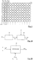
Par exemple, la séquence illustrée en
- un préambule IAM1 composé de trois symboles de préambule, référencés p m,0, p m,1 et p m,2, avec m l'indice pour les fréquences porteuses et 0, 1, 2 l'indice temporel, chaque symbole de préambule comprenant M pilotes dont la valeur et l'emplacement à l'émission sont connus d'au moins un récepteur destiné à effectuer une réception du signal à porteuses multiples ; et
- des symboles de données.
- IAM1 a preamble composed of three preamble symbols, referenced p m, 0, p m, p 1 and m 2, m is the index for the carrier frequency and 0, 1, 2 the time index, each preamble symbol comprising M pilots whose value and location on transmission are known to at least one receiver for performing multi-carrier signal reception; and
- data symbols.
La structure du préambule IAM1 est telle que :
- p m,0 = p m,2 = 0,
- p 4k,1 = p 4k+1,1 = 1, et
- p 4k+2,1 = p 4k+3,1 = -1,
- p m , 0 = p m , 2 = 0,
- p 4 k , 1 = p 4 k +1.1 = 1, and
- p 4 = p k + 2.1 + 3.1 = 4 k -1,
Par conséquent, le pilote reçu à la m-ième fréquence et pour le symbole p m,1 d'indice temporel 1, entaché d'interférences (encore appelé « pseudo-pilote »), peut s'écrire : ![]()
![]()
![]()
![]()
En notant ![]()
![]()
![]()
![]()
![]()
![]()
D'autres structures de préambule de même longueur (trois symboles de préambule, c'est-à-dire 3M pilotes) ont également été proposées, aboutissant à des expressions encore plus favorables pour la puissance du « pseudo-pilote », comme proposé dans le document
On observe que, dans tous les cas, la qualité de l'estimation de canal reste en relation directe avec le paramètre β 0. Ainsi, les meilleurs résultats (c'est-à-dire les valeurs les plus élevées du paramètre β 0) sont obtenus avec des filtres orthogonaux bien localisés en temps et en fréquence.It is observed that, in all cases, the quality of the channel estimate remains in direct relation with the parameter β 0 . Thus, the best results (ie the highest values of the parameter β 0 ) are obtained with orthogonal filters well localized in time and in frequency.
Ainsi, les filtres prototypes classiquement utilisés sont la fonction IOTA (en anglais « Isotropic Orthogonal Transform Algorithm ») discrétisée et tronquée à une longueur 4M, ou le filtre prototype de longueur M appelé TFL (« Time Frequency Localization ») optimisé pour un critère défini, pour un signal à valeurs réelles, par un paramètre de localisation temps-fréquence : ![]()

![]()

![]()
![]()
On note que la localisation temps-fréquence ξ d'un signal discret possède une borne supérieure ξ≤1.Note that the time-frequency location ξ of a discrete signal has an upper bound ξ ≤1.
L'ensemble de ces techniques permet d'obtenir des structures de préambule permettant d'accroître la puissance du « pseudo-pilote », et donc d'accroître le niveau d'interférence produit en réception. Les porteuses du préambule sont ensuite mises en forme en utilisant des filtres prototypes orthogonaux ou bi-orthogonaux, classiquement utilisés dans le cadre de modulations OFDM/OQAM ou BFDM/OQAM respectivement.All of these techniques make it possible to obtain preamble structures making it possible to increase the power of the "pseudo-pilot" and thus to increase the level of interference produced in reception. The preamble carriers are then shaped using orthogonal or bi-orthogonal prototype filters, conventionally used in the context of OFDM / OQAM or BFDM / OQAM modulations, respectively.
Malheureusement, un inconvénient de cette approche d'estimation par préambule visant à produire un préambule qui augmente la puissance de l'interférence en réception est qu'elle ne permet pas de garantir, pour une structure de préambule donnée, que l'on obtienne un « pseudo-pilote » d'énergie maximale.Unfortunately, a disadvantage of this preamble estimation approach aimed at producing a preamble that increases the power of the reception interference is that it does not make it possible to guarantee, for a given preamble structure, that one obtains a "Pseudo-pilot" of maximum energy.
De plus, le fait de disposer d'une orthogonalité au sens réel rend le processus d'estimation de canal plus délicat.In addition, having orthogonality in the real sense makes the channel estimation process more difficult.
Il existe donc un besoin pour une nouvelle technique d'émission et/ou de réception d'un signal à porteuses multiples comprenant un préambule ayant subi une modulation de type OFDM/OQAM ou BFDM/OQAM permettant de remédier à au moins certains de ces inconvénients, et notamment d'estimer correctement le canal de transmission.There is therefore a need for a new technique for transmitting and / or receiving a multicarrier signal comprising an OFDM / OQAM or BFDM / OQAM-type preamble making it possible to remedy at least some of these drawbacks. , and in particular to correctly estimate the transmission channel.
L'invention propose une solution nouvelle qui ne présente pas l'ensemble de ces inconvénients de l'art antérieur, sous la forme d'un procédé d'émission d'un signal à porteuses multiples formé d'une succession temporelle de symboles multiporteuses, comprenant :
- au moins un préambule formé d'au moins trois symboles multiporteuses consécutifs, dits symboles de préambule, portant des éléments de données à valeur complexe associés chacun à une porteuse dudit signal, et
- des symboles multiporteuses, dits symboles de données, portant des éléments de données à valeur réelle associés chacun à une porteuse dudit signal,
- un filtrage, par un premier filtre prototype, des porteuses portant lesdits éléments de données à valeur complexe correspondant auxdits symboles de préambule, permettant de mettre en forme lesdits symboles de préambule, et
- un filtrage, par un deuxième filtre prototype distinct dudit premier filtre prototype, des porteuses portant lesdits éléments de données à valeur réelle correspondant auxdits symboles de données, permettant de mettre en forme lesdits symboles de données.
- at least one preamble formed by at least three consecutive multicarrier symbols, called preamble symbols, carrying complex value data elements each associated with a carrier of said signal, and
- multicarrier symbols, called data symbols, carrying real-valued data elements each associated with a carrier of said signal,
- filtering, by a first prototype filter, carriers carrying said complex value data elements corresponding to said preamble symbols, for shaping said preamble symbols, and
- filtering, by a second prototype filter separate from said first prototype filter, carriers carrying said real-valued data elements corresponding to said data symbols, for shaping said data symbols.
On se place ainsi dans le contexte de l'émission de signaux multiporteuses comprenant un préambule, et pour lesquels les porteuses sont mises en forme par des filtres prototypes, de type OFDM/OQAM ou BFDM/OQAM par exemple.It is thus placed in the context of the transmission of multicarrier signals comprising a preamble, and for which the carriers are shaped by prototype filters, of the OFDM / OQAM or BFDM / OQAM type, for example.
On rappelle que, dans ce contexte, les symboles de données portent des éléments de données à valeur réelle. Ainsi, l'efficacité spectrale de l'OFDM/OQAM est identique à celle de l'OFDM classique sans intervalle de garde. En effet, en notant v 0 l'espacement entre deux porteuses adjacentes du multiplex, et τ 0 l'espacement temporel entre deux éléments de données à valeurs réelles, on transmet pour un même espacement inter-porteuses v 0 :
- en OFDM/OQAM, une valeur réelle par porteuse tous les intervalles de temps τ0 ;
- en OFDM classique sans intervalle de garde, une valeur complexe (i.e. deux valeurs réelles) tous les 2 × τ0.
- OFDM / OQAM, a real value per carrier all the time intervals τ 0;
- in conventional OFDM without guard interval, a complex value (ie two real values) every 2 × τ 0 .
Selon l'invention, il est alors possible d'utiliser des filtres prototypes distincts pour la mise en forme des symboles de préambule et des symboles de données.According to the invention, it is then possible to use separate prototype filters for shaping preamble symbols and data symbols.
En particulier, les symboles de préambule peuvent être mis en forme par un premier filtre prototype quelconque, c'est-à-dire non nécessairement orthogonal ou bi-orthogonal.In particular, the preamble symbols can be shaped by any first prototype filter, that is to say not necessarily orthogonal or bi-orthogonal.
De cette façon, la contrainte d'orthogonalité au sens réel pour les symboles de préambule qui, selon l'art antérieur, limitait le choix des filtres prototypes ne s'applique plus. Au contraire, le premier filtre prototype n'est pas nécessairement orthogonal.In this way, the orthogonality constraint in the real sense for the preamble symbols which, according to the prior art, limited the choice of the prototype filters no longer applies. On the contrary, the first prototype filter is not necessarily orthogonal.
Les symboles de données sont quant à eux classiquement mis en forme au moyen d'un deuxième filtre prototype orthogonal ou bi-orthogonal, de type IOTA ou TFL par exemple. Cela signifie que les translatées dans l'espace temps/fréquence du deuxième filtre prototype sont orthogonales ou bi-orthogonales entre elles, ce qui permet une meilleure localisation fréquentielle du signal multiporteuse.The data symbols are conventionally formatted by means of a second orthogonal or bi-orthogonal prototype filter, of the IOTA or TFL type, for example. This means that the translates in the time / frequency space of the second prototype filter are orthogonal or bi-orthogonal to each other, which allows a better frequency localization of the multicarrier signal.
On utilise ainsi deux filtres prototypes distincts, l'un pour le préambule, déterminé de façon à obtenir une bonne estimation du canal de transmission, et l'autre pour les données utiles, orthogonal ou bi-orthogonal, pour assurer une bonne transmission de la charge utile.Thus, two distinct prototype filters are used, one for the preamble, determined in order to obtain a good estimate of the transmission channel, and the other for the useful data, orthogonal or bi-orthogonal, to ensure a good transmission of the payload.
En effet, les inventeurs ont constaté que les solutions de l'art antérieur qui utilisent un unique filtre prototype choisi en fonction de critères liés à la transmission des données utiles, et non à l'estimation de canal, ne conduisent pas forcément à la meilleure estimation de canal. Le rôle du filtre prototype est donc non négligeable pour obtenir une bonne estimation de canal.Indeed, the inventors have found that the solutions of the prior art that use a single prototype filter chosen according to criteria related to the transmission of useful data, and not to the channel estimate, do not necessarily lead to the best channel estimation. The role of the prototype filter is therefore not negligible to obtain a good channel estimate.
Selon un aspect particulier de l'invention, le préambule comprend deux symboles de préambule d'extrémité constitués d'éléments de données portant une valeur nulle, encadrant au moins un symbole de préambule central constitué de pilotes pi portant une valeur égale à 1 ou -1, avec i ∈ [0,M-1] l'indice de la porteuse associée au pilote pi et M le nombre de porteuses associées au symbole de préambule central, tel que, pour k = 0,...,M/4-1 :
- p 4k = p 4k+1 = 1 et
- P 4k+2 = p 4k+3 = -1.
- p 4 k = p 4 k +1 = 1 and
- P 4 k 2 = k 3 p 4 = - 1.
Cette structure particulière de préambule, encore appelée IAM1 et décrite en relation avec l'art antérieur, permet notamment d'augmenter l'interférence résiduelle en réception. Combinée à une mise en forme par un filtre prototype non nécessairement orthogonal (premier filtre prototype), une telle structure permet de simplifier et d'améliorer les performances du processus d'estimation de canal mis en oeuvre en réception.This particular preamble structure, also called IAM1 and described in relation with the prior art, makes it possible in particular to increase the residual interference in reception. Combined with formatting by a not necessarily orthogonal prototype filter (first prototype filter), such a structure makes it possible to simplify and improve the performance of the channel estimation process implemented in reception.
Selon une variante, le préambule comprend au moins un pilote portant une valeur imaginaire pure.According to one variant, the preamble comprises at least one pilot carrying a pure imaginary value.
Bien entendu, le nombre de symboles de préambule peut être supérieur ou égal à trois. Toutefois, on considère qu'un préambule présentant trois symboles multiporteuses est le plus efficace pour l'estimation de canal.Of course, the number of preamble symbols may be greater than or equal to three. However, it is considered that a preamble with three multicarrier symbols is most effective for channel estimation.
Selon un mode de réalisation particulier de l'invention, le premier filtre prototype g[k] prend la forme discrète suivante : ![]()
- K = Lg -1, avec Lg la longueur dudit premier filtre prototype ;
- F(0) une constante ;
- Γ(·) la fonction gamma ; et
- Tr un paramètre de résolution temporelle.
- K = L g -1 , with Lg the length of said first prototype filter;
- F (0) a constant;
- Γ (·) the gamma function; and
- T r a time resolution parameter.
La fonction gamma est bien connue de l'Homme du Métier. Pour des entiers ![]()
- [Γ(k)]-1 = 0 pour k ≤ 0 ;
- Γ(k) = (k-1)! pour k ≠ 0 et
- [Γ ( k )] -1 = 0 for k ≤ 0;
- Γ ( k ) = ( k -1)! for k ≠ 0 and
Ce premier filtre prototype est utilisé uniquement pendant la durée de transmission du préambule, et est déterminé de façon à obtenir une bonne estimation du canal de transmission. Il n'est pas nécessairement orthogonal, ou bi-orthogonal, mais permet de maximiser le paramètre β 0 défini en relation avec l'art antérieur, encore appelé premier paramètre.This first prototype filter is used only during the duration of transmission of the preamble, and is determined so as to obtain a good estimate of the transmission channel. It is not necessarily orthogonal, or bi-orthogonal, but makes it possible to maximize the parameter β 0 defined in relation with the prior art, also called first parameter.
En particulier, ce premier filtre prototype est bien localisé dans le domaine temporel et fréquentiel, et permet de garantir que l'approximation donnée par l'équation 
Selon une première variante, le procédé d'émission comprend une étape de détermination du paramètre de résolution temporelle Tr du premier filtre prototype g[k], à partir d'un premier paramètre β 0 et d'un deuxième paramètre βI , tels que :
-

-

-
-
Selon cette première variante, l'étape de détermination permet de maximiser le premier paramètre β 0 et/ou de minimiser le deuxième paramètre βI .According to this first variant, the determination step makes it possible to maximize the first parameter β 0 and / or to minimize the second parameter β I.
Selon une deuxième variante, le procédé d'émission comprend une étape de détermination dudit paramètre de résolution temporelle Tr du premier filtre prototype g[k], à partir d'une combinaison linéaire d'un premier paramètre β 0 et d'un deuxième paramètre βI , égale à wβ 0-(1-w)βI , telle que :
- w est un facteur de pondération tel que 0 ≤ w ≤ 1 ;
-

-

- w is a weighting factor such that 0 ≤ w ≤ 1;
-
-
Selon cette deuxième variante, l'étape de détermination permet de maximiser la combinaison linéaire wβ 0 - (1- w)βI .According to this second variant, the determination step makes it possible to maximize the linear combination wβ 0 - (1- w ) β I.
Un autre aspect de l'invention concerne un programme d'ordinateur comportant des instructions pour la mise en oeuvre du procédé d'émission tel que décrit ci-dessus, lorsque ledit programme est exécuté par un processeur.Another aspect of the invention relates to a computer program comprising instructions for implementing the transmission method as described above, when said program is executed by a processor.
On note en effet que le procédé selon l'invention peut être mis en oeuvre de diverses manières, notamment sous forme câblée ou sous forme logicielle.It is noted that the method according to the invention can be implemented in various ways, particularly in hard-wired form or in software form.
Dans un autre mode de réalisation, l'invention concerne un dispositif d'émission d'un signal à porteuses multiples formé d'une succession temporelle de symboles multiporteuses, comprenant :
- au moins un préambule formé d'au moins trois symboles multiporteuses consécutifs, dits symboles de préambule, portant des éléments de données à valeur complexe associés chacun à une porteuse dudit signal, et
- des symboles multiporteuses, dits symboles de données, portant des éléments de données à valeur réelle associés chacun à une porteuse dudit signal.
- at least one preamble formed by at least three consecutive multicarrier symbols, called preamble symbols, carrying complex value data elements each associated with a carrier of said signal, and
- multicarrier symbols, called data symbols, carrying real-valued data elements each associated with a carrier of said signal.
Selon l'invention, le dispositif d'émission comprend des moyens de mise en forme des porteuses, comprenant :
- un premier filtre prototype filtrant les porteuses portant lesdits éléments de données à valeur complexe correspondant auxdits symboles de préambule, permettant de mettre en forme lesdits symboles de préambule, et
- un deuxième filtre prototype, distinct dudit premier filtre prototype, filtrant les porteuses portant lesdits éléments de données à valeur réelle correspondant auxdits symboles de données, permettant de mettre en forme lesdits symboles de données.
- a first prototype filter filtering the carriers carrying said complex value data elements corresponding to said preamble symbols, for shaping said preamble symbols, and
- a second prototype filter, separate from said first prototype filter, filtering the carriers carrying said real value data elements corresponding to said data symbols, for shaping said data symbols.
Un tel dispositif d'émission est notamment adapté à mettre en oeuvre le procédé d'émission décrit précédemment. Il s'agit par exemple de l'émetteur d'une paire émission-réception ou d'un modem PLC.Such an emission device is particularly suitable for implementing the transmission method described above. This is for example the transmitter of a transceiver pair or a PLC modem.
Ce dispositif pourra bien sûr comporter les différentes caractéristiques relatives au procédé d'émission selon l'invention.This device may of course include the various characteristics relating to the transmission method according to the invention.
L'invention concerne aussi un signal à porteuses multiples formé d'une succession temporelle de symboles multiporteuses, comprenant :
- au moins un préambule formé d'au moins trois symboles multiporteuses consécutifs, dits symboles de préambule, portant des éléments de données à valeur complexe associés chacun à une porteuse dudit signal, et
- des symboles multiporteuses, dits symboles de données, portant des éléments de données à valeur réelle associés chacun à une porteuse dudit signal.
- at least one preamble formed by at least three consecutive multicarrier symbols, called preamble symbols, carrying complex value data elements each associated with a carrier of said signal, and
- multicarrier symbols, called data symbols, carrying real-valued data elements each associated with a carrier of said signal.
Selon l'invention, les porteuses portant les éléments de données à valeur complexe correspondant aux symboles de préambule d'un tel signal sont mises en forme par un premier filtre prototype, et les porteuses portant les éléments de données à valeur réelle correspondant aux symboles de données sont mises en forme par un deuxième filtre prototype, distinct du premier filtre prototype.According to the invention, the carriers carrying the complex value data elements corresponding to the preamble symbols of such a signal are shaped by a first signal. prototype filter, and the carriers carrying the real-valued data elements corresponding to the data symbols are shaped by a second prototype filter, distinct from the first prototype filter.
Un tel signal peut notamment être émis par le procédé d'émission décrit ci-dessus. Ce signal pourra bien sûr comporter les différentes caractéristiques relatives au procédé d'émission selon l'invention.Such a signal can in particular be emitted by the transmission method described above. This signal may of course include the various characteristics relating to the transmission method according to the invention.
Un autre aspect de l'invention concerne un procédé de réception d'un signal à porteuses multiples formé d'une succession temporelle de symboles multiporteuses, comprenant à l'émission :
- au moins un préambule formé d'au moins trois symboles multiporteuses consécutifs, dits symboles de préambule, portant des éléments de données à valeur complexe associés chacun à une porteuse dudit signal, et
- des symboles multiporteuses, dits symboles de données, portant des éléments de données à valeur réelle associés chacun à une porteuse dudit signal.
- at least one preamble formed by at least three consecutive multicarrier symbols, called preamble symbols, carrying complex value data elements each associated with a carrier of said signal, and
- multicarrier symbols, called data symbols, carrying real-valued data elements each associated with a carrier of said signal.
Selon l'invention, un tel procédé de réception comprend une étape de mise en forme des porteuses reçues, mettant en oeuvre :
- un filtrage des porteuses reçues associées aux symboles de préambule par un premier filtre prototype, et
- un filtrage des porteuses reçues associées aux symboles de données par un deuxième filtre prototype, distinct dudit premier filtre prototype.
- a filtering of the received carriers associated with the preamble symbols by a first prototype filter, and
- a filtering of the received carriers associated with the data symbols by a second prototype filter, distinct from said first prototype filter.
On note que du fait du passage dans le canal de transmission, les éléments de données subissent des interférences (intra porteuse et ou inter porteuses). Ainsi, les éléments de données qui présentaient une valeur réelle côté émission peuvent présenter une valeur complexe côté réception.It is noted that due to the passage in the transmission channel, the data elements undergo interference (intra carrier and or inter carriers). Thus, data items that had a real value on the sending side may have a complex value on the receiving end.
Un tel procédé de réception est notamment adapté à recevoir un signal à porteuses multiples émis selon le procédé d'émission décrit ci-dessus.Such a reception method is in particular adapted to receive a multicarrier signal transmitted according to the transmission method described above.
Les caractéristiques et avantages de ce procédé de réception sont les mêmes que ceux du procédé d'émission. Par conséquent, ils ne sont pas détaillés plus amplement.The characteristics and advantages of this reception method are the same as those of the transmission method. Therefore, they are not detailed further.
En particulier, le premier filtre prototype mis en oeuvre en réception est identique au premier filtre prototype mis en oeuvre en émission. En effet, pour pouvoir réaliser l'estimation de canal, le récepteur doit connaître parfaitement les valeurs et emplacements des éléments de données des symboles de préambule.In particular, the first prototype filter implemented in reception is identical to the first prototype filter implemented in transmission. Indeed, to be able to realize the channel estimation, the receiver must know perfectly the values and locations of the data elements of the preamble symbols.
Le deuxième filtre prototype mis en oeuvre en réception n'est quant à lui pas nécessairement identique au deuxième filtre prototype mis en oeuvre en émission.The second prototype filter implemented in reception is not necessarily identical to the second prototype filter implemented in transmission.
L'invention concerne ainsi aussi la construction des filtres prototypes implantés dans les émetteurs ou les récepteurs.The invention thus also relates to the construction of prototype filters implanted in transmitters or receivers.
Un autre aspect de l'invention concerne un programme d'ordinateur comportant des instructions pour la mise en oeuvre du procédé de réception tel que décrit ci-dessus, lorsque ledit programme est exécuté par un processeur.Another aspect of the invention relates to a computer program comprising instructions for carrying out the reception method as described above, when said program is executed by a processor.
On note en effet que le procédé selon l'invention peut être mis en oeuvre de diverses manières, notamment sous forme câblée ou sous forme logicielle.It is noted that the method according to the invention can be implemented in various ways, particularly in hard-wired form or in software form.
Dans un autre mode de réalisation, l'invention concerne un dispositif de réception d'un signal à porteuses multiples formé d'une succession temporelle de symboles multiporteuses, comprenant à l'émission :
- au moins un préambule formé d'au moins trois symboles multiporteuses consécutifs, dits symboles de préambule, portant des éléments de données à valeur complexe associés chacun à une porteuse du signal, et
- des symboles multiporteuses, dits symboles de données, portant des éléments de données à valeur réelle associés chacun à une porteuse du signal.
- at least one preamble formed of at least three consecutive multicarrier symbols, called preamble symbols, carrying complex value data elements each associated with a signal carrier, and
- multicarrier symbols, called data symbols, carrying real-valued data elements each associated with a carrier of the signal.
Selon l'invention, un tel dispositif de réception comprend des moyens de mise en forme des porteuses reçues, mettant en oeuvre :
- un premier filtre prototype filtrant les porteuses reçues associées aux symboles de préambule, et
- un deuxième filtre prototype, distinct du premier filtre prototype, filtrant les porteuses reçues associées aux symboles de données.
- a first prototype filter filtering the received carriers associated with the preamble symbols, and
- a second prototype filter, separate from the first prototype filter, filtering the received carriers associated with the data symbols.
Un tel dispositif de réception est notamment adapté à mettre en oeuvre le procédé de réception décrit précédemment. Il s'agit par exemple du récepteur d'une paire émission-réception ou d'un modem PLC, d'un boîtier décodeur (« set top box »), etc.Such a reception device is particularly suitable for implementing the reception method described above. This is for example the receiver of a transceiver pair or a PLC modem, a set top box, and so on.
Ce dispositif pourra bien sûr comporter les différentes caractéristiques relatives au procédé de réception selon l'invention.This device may of course include the various characteristics relating to the reception method according to the invention.
D'autres caractéristiques et avantages de l'invention apparaîtront plus clairement à la lecture de la description suivante d'un mode de réalisation particulier, donné à titre de simple exemple illustratif et non limitatif, et des dessins annexés, parmi lesquels :
- la
figure 1 , décrite en relation avec l'art antérieur, illustre une structure de préambule particulière ; - les
figures 2A et 2B présentent les principales étapes mises en oeuvre pour une émission OFDM/OQAM mettant en oeuvre deux fonctions prototypes distinctes, selon un mode de réalisation de l'invention ;
- la
figure 3 illustre la structure d'un signal multiporteuse selon l'invention ; - la
figure 4 présente les principales étapes mises en oeuvre pour une réception OFDM/OQAM mettant en oeuvre deux fonctions prototypes distinctes, selon un mode de réalisation de l'invention ; - les
figures 5A à 5C illustrent la réponse impulsionnelle du filtre prototype g[k] ou g 2[k] pour différentes valeurs du paramètre de résolution temporelle Tr , ainsi que les masques d'interférence associés ; - la
figure 6 illustre la sélection d'un filtre prototype présentant un paramètre de résolution temporelle optimal ; - la
figure 7 illustre les performances de l'invention par rapport aux solutions de l'art antérieur et à la solution idéale, pour un terme de phase φ 0 = 0 ; - les
figures 8 présentent respectivement la structure d'un dispositif d'émission et d'un dispositif de réception mettant en oeuvre deux filtrages prototypes distincts selon un mode de réalisation particulier de l'invention.et 9
- the
figure 1 , described in relation to the prior art, illustrates a particular preamble structure; - the
Figures 2A and 2B present the main steps implemented for an OFDM / OQAM transmission implementing two distinct prototype functions, according to an embodiment of the invention;
- the
figure 3 illustrates the structure of a multicarrier signal according to the invention; - the
figure 4 presents the main steps implemented for an OFDM / OQAM reception implementing two distinct prototype functions, according to one embodiment of the invention; - the
FIGS. 5A to 5C illustrate the impulse response of the prototype filter g [ k ] or g 2 [ k ] for different values of the temporal resolution parameter T r , as well as the associated interference masks; - the
figure 6 illustrates the selection of a prototype filter having an optimal temporal resolution parameter; - the
figure 7 illustrates the performance of the invention compared with the solutions of the prior art and the ideal solution for a phase term φ 0 = 0; - the
Figures 8 and 9 respectively present the structure of a transmitting device and a receiving device implementing two separate prototype filtering according to a particular embodiment of the invention.
Le principe général de l'invention repose sur une mise en forme spécifique des porteuses d'un signal à porteuses multiples comprenant au moins un préambule, formé d'au moins trois symboles de préambule, et des symboles de données. Un tel préambule est par exemple placé en début de trame, une trame étant constituée d'au moins un symbole de préambule et d'un ensemble de symboles de données.The general principle of the invention is based on a specific shaping of carriers of a multicarrier signal comprising at least one preamble, formed by at least three preamble symbols, and data symbols. Such a preamble is for example placed at the beginning of the frame, a frame consisting of at least one preamble symbol and a set of data symbols.
Cette mise en forme spécifique des porteuses consiste à appliquer un filtre prototype (pour un signal discret), ou une fonction prototype (pour un signal continu), distinct aux porteuses correspondant aux symboles de préambule et aux symboles de données. Ces filtres prototypes peuvent être implantés dans un émetteur et dans un récepteur correspondant.This specific formatting of the carriers consists in applying a prototype filter (for a discrete signal), or a prototype function (for a continuous signal), distinct to the carriers corresponding to the preamble symbols and the data symbols. These prototype filters can be implanted in a transmitter and in a corresponding receiver.
Ainsi, on utilise selon l'invention un premier filtre prototype (ou fonction prototype) dédié uniquement à la transmission du préambule (symboles de préambule), qui n'est pas nécessairement orthogonal, et qui permette d'accroître le niveau d'interférence produit en réception par rapport aux techniques de l'art antérieur.Thus, according to the invention, a first prototype filter (or prototype function) dedicated solely to the transmission of the preamble (preamble symbols), which is not necessarily orthogonal, and which makes it possible to increase the level of interference produced, is used. in reception compared to the techniques of the prior art.
Un deuxième filtre prototype (ou fonction prototype) est utilisé pour la transmission des données utiles (symboles de données), qui est quant à lui orthogonal, et qui permet une meilleure localisation fréquentielle des symboles de données du signal multiporteuse.A second prototype filter (or prototype function) is used for the transmission of useful data (data symbols), which is orthogonal, and which allows a better frequency localization of the data symbols of the multicarrier signal.
L'utilisation de ces deux filtres prototypes distincts permet notamment d'améliorer l'estimation du canal de transmission, et donc d'améliorer les gains de transmission.The use of these two distinct prototype filters makes it possible in particular to improve the estimate of the transmission channel, and thus to improve the transmission gains.
On décrit ci-après un exemple de mise en oeuvre de l'invention dans le cadre d'une modulation OFDM/OQAM, pour laquelle les symboles de préambule sont insérés en sortie d'une étape de modulation. On note que ces symboles de préambule pourraient également être insérés dans le signal avant l'étape de modulation. Bien entendu, l'invention s'applique à tout système de transmission mettant en oeuvre une modulation à porteuses multiples pour laquelle les porteuses sont mises en forme par une fonction prototype, et une estimation du canal par préambule.An exemplary implementation of the invention in the context of an OFDM / OQAM modulation is described below, for which the preamble symbols are inserted at the output of a modulation step. It is noted that these preamble symbols could also be inserted in the signal before the modulation step. Of course, the invention applies to any transmission system implementing a multicarrier modulation for which the carriers are shaped by a prototype function, and an estimation of the channel by preamble.
Plus précisément, comme illustré en
Par exemple, cette étape de modulation 21 comprend les opérations usuelles de transformation des données utiles b en éléments de données à valeur complexe, décomposition des éléments de données à valeur complexe en éléments de données à valeur réelle am,n (correspondant aux composantes réelles et imaginaires de l'élément de données à valeur complexe), correction de phase et d'amplitude (mettant en oeuvre une multiplication complexe permettant de prendre en compte un terme de phase spécifique et la longueur du filtre prototype utilisé pour les données utiles, noté deuxième filtre prototype), passage du domaine fréquentiel au domaine temporel au moyen d'une transformée de Fourier inverse, implémentation du deuxième filtre prototype sous sa forme dite polyphase.For example, this
En d'autres termes, les porteuses portant les éléments de données à valeur réelle am,n , correspondant à des symboles de données, sont mises en forme par le deuxième filtre prototype.In other words, the carriers carrying the real-valued data elements m, n , corresponding to data symbols, are shaped by the second prototype filter.
Par exemple, la deuxième fonction prototype est la fonction IOTA, ou la fonction TFL, ou tout autre fonction prototype présentant des propriétés d'orthogonalité.For example, the second prototype function is the IOTA function, or the TFL function, or any other prototype function with orthogonality properties.
Après une conversion parallèle/série, on obtient en sortie du modulateur le signal OFDM/OQAM, noté s'[k] sous forme discrète, ou s'(t) sous forme continue après passage dans un convertisseur numérique analogique.After a parallel / series conversion, the OFDM / OQAM signal, denoted s ' [ k ] in discrete form, or s ' ( t ) in continuous form after passing through a digital-analog converter, is obtained at the output of the modulator.
Le procédé d'émission selon un mode de réalisation particulier de l'invention comprend également une étape 22 d'insertion d'un préambule. Classiquement, un tel préambule est inséré dans une trame, avant les symboles de données.The transmission method according to a particular embodiment of the invention also comprises a
Un tel préambule est formé d'au moins trois symboles de préambule, portant chacun des éléments de données à valeur complexe (par complexe, on entend ici également à valeur purement réelle ou purement imaginaire). Les porteuses portant les éléments de données à valeur complexe cm,n , correspondant à ces symboles de préambule, sont mises en forme par un premier filtre prototype, distinct du deuxième filtre prototype.Such a preamble is formed of at least three preamble symbols, each carrying complex value data elements (by complex, here also means purely real or purely imaginary value). The carriers carrying the complex value data elements c m, n , corresponding to these preamble symbols, are shaped by a first prototype filter, distinct from the second prototype filter.
Par exemple, ce premier filtre prototype g[k], encore appelé filtre de Doroslovacki modifié, prend la forme discrète suivante : ![]()
- K = Lg -1, avec Lg la longueur du premier filtre prototype ;
- F(0) une constante ;
- Γ(·) la fonction gamma ; et
- Tr un paramètre de résolution temporelle.
- K = L g -1, with L g the length of the first prototype filter;
- F (0) a constant;
- Γ (·) the gamma function; and
- T r a time resolution parameter.
Un tel filtre utilisé pour la transmission du préambule n'est pas nécessairement orthogonal.Such a filter used for transmitting the preamble is not necessarily orthogonal.
On note s[k] le signal à porteuses multiples sous forme discrète (ou s(t) sous forme continue) obtenu après insertion du préambule.We denote by s [ k ] the multicore signal in discrete form (or s ( t ) in continuous form) obtained after insertion of the preamble.
La
On considère ainsi un modulateur OFDM/OQAM 23, permettant de délivrer un signal à porteuses multiples s[k] formé de symboles multiporteuses de durée τ 0. Par exemple, une trame d'un tel signal s[k] comprend trois symboles de préambule sur les trois premières périodes ([0,3τ0]) et des symboles de données sur les périodes suivantes ([4τ 0,...]).An OFDM /
Le modulateur OFDM/OQAM 23 met en oeuvre les étapes classiques de transformation de Fourier inverse et de filtrage prototype.The OFDM /
Toutefois, selon l'invention, les coefficients du filtre prototype d'un tel modulateur OFDM/OQAM sont :
- soit ceux d'un premier filtre prototype F 1 quelconque, par exemple un filtre de Doroslovački modifié, permettant de mettre en forme les trois symboles de préambule sur les trois premières périodes ([0,3τ 0]) à partir de données de préambule p,
- soit ceux d'un deuxième filtre prototype F 2 orthogonal, par exemple un filtre IOTA ou TFL, permettant de mettre en forme les symboles de données sur les périodes suivantes ([4τ0,...]) à partir des données utiles b.
- either those of a first prototype filter F 1 of any kind, for example a modified Doroslovački filter, making it possible to format the three preamble symbols over the first three periods ([0.3 τ 0 ]) from preamble data p ,
- those of a second orthogonal F 2 prototype filter, for example an IOTA filter or TFL, for formatting the data symbols over the following periods ([4τ 0 , ...]) from the useful data b.
Un tel modulateur OFDM/OQAM permet donc de basculer d'un premier filtre F 1 à un deuxième filtre F 2 (puis éventuellement de rebasculer vers le premier filtre et ainsi de suite, si plusieurs préambules sont insérés dans le signal à porteuses multiples) pour moduler d'une part les données de préambule p et d'autre part les données utiles b. Such an OFDM / OQAM modulator thus makes it possible to switch from a first filter F 1 to a second filter F 2 (and then possibly to switch back to the first filter and so on, if several preambles are inserted in the multicarrier signal) for modulate on the one hand the preamble data p and on the other hand the useful data b.
La
- au moins un préambule P, formé d'au moins trois symboles de préambule p m,0 , p m,1, p m,2 comprenant des éléments de données à valeur complexe cm,n, associés chacun à une porteuse du signal, et
- des données D comprenant des symboles de données d m,3, d m,4, d m,5, etc, comprenant des éléments de données à valeur réelle a m,n associés chacun à une porteuse du signal,
- at least one preamble P, formed by at least three preamble symbols p m, 0 , p m, 1 , p m , 2 comprising complex value data elements c m, n , each associated with a signal carrier, and
- data D comprising data symbols d m , 3 , d m , 4 , d m , 5 , etc., comprising real-valued data elements a m , n each associated with a carrier of the signal,
Les éléments de données des symboles de préambule sont encore appelés pilotes, leurs valeur et emplacement à l'émission étant connus d'au moins un récepteur destiné à effectuer une réception du signal à porteuses multiples. On rappelle en effet que dans le cadre d'une estimation par préambule, le récepteur doit connaître exactement le contenu du préambule, c'est-à-dire la position des pilotes dans l'espace temps/fréquence et leur valeur.The data elements of the preamble symbols are also called pilots, their value and location on transmission being known to at least one receiver for performing reception of the multicarrier signal. It is recalled that in the context of a preamble estimation, the receiver must know exactly the content of the preamble, that is to say the position of the pilots in the time / frequency space and their value.
Des étapes sensiblement identiques sont mises en oeuvre côté réception.Substantially identical steps are implemented on the reception side.
Plus précisément, comme illustré en
Les symboles de préambule reçus sont alors de nouveau mis en forme par le premier filtre prototype. En d'autres termes, les filtres prototypes utilisés pour la transmission du préambule (appliqués aux symboles de préambule), et donc pour la partie estimation de canal, sont identiques à l'émission et à la réception.The received preamble symbols are then again formatted by the first prototype filter. In other words, the prototype filters used for transmitting the preamble (applied to the preamble symbols), and therefore for the channel estimation part, are identical to the transmission and reception.
Les symboles de données reçus subissent quant à eux un traitement différent. Plus précisément, selon ce mode de réalisation particulier, le procédé de réception comprend une étape 42 de démodulation OFDM/OQAM classique, mettant en oeuvre une estimation du canal de transmission à partir du préambule P, et permettant d'obtenir une estimation des données utiles initiales sous forme binaire, notées b̂, à partir des symboles de données reçus et de l'estimation du canal de transmission.The data symbols received undergo a different treatment. More specifically, according to this particular embodiment, the reception method comprises a conventional OFDM /
Par exemple, cette étape de démodulation 42 comprend les opérations usuelles d'estimation du canal de transmission à partir du préambule P, filtrage des symboles de données reçus par la deuxième fonction prototype, passage du domaine temporel au domaine fréquentiel au moyen d'une transformée de Fourier directe, correction de phase et d'amplitude (mettant en oeuvre une multiplication complexe permettant de prendre en compte un terme de phase spécifique et la longueur du deuxième filtre prototype), extraction de la partie réelle et recombinaison des données réelles par deux, pour former une donnée complexe, et reconstruire les données utiles b̂.For example, this
On rappelle que lors d'une estimation de canal en OFDM/OQAM par un préambule, l'émetteur et le récepteur connaissent les éléments de données du préambule (pilotes) et le filtre prototype utilisé en émission, et via l'équation permettant d'approximer la composante imaginaire correspondant à l'interférence obtenue à un emplacement temps/fréquence (par exemple 
Le canal peut ainsi être estimé sur chacune des porteuses du multiplex. Le choix des paramètres du système (durée symbole, longueur de trame, etc...) assure que le canal varie lentement par rapport au temps symbole τ 0. On suppose alors le canal quasi-constant sur une trame (où une trame étant constituée d'au moins un symbole de préambule et d'un ensemble de symboles de données). On peut donc utiliser l'estimée du canal déterminée pour le ou les symboles de préambule pour l'ensemble des symboles de données de la trame.The channel can thus be estimated on each of the carriers of the multiplex. The choice of the system parameters (symbol duration, frame length, etc.) ensures that the channel varies slowly with respect to the symbol time τ 0 . The quasi-constant channel is assumed on a frame (where a frame consists of at least one preamble symbol and a set of data symbols). It is therefore possible to use the estimate of the determined channel for the preamble symbol (s) for all the data symbols of the frame.
On note que selon ce mode de réalisation, les filtres prototypes utilisés pour la transmission des données (appliqués aux symboles de données), et donc pour la partie charge utile, sont identiques à l'émission et à la réception, par exemple dans le cas d'une transmission OFDM/OQAM mettant en oeuvre un filtre à phase linéaire. Toutefois, cette caractéristique n'est pas obligatoire, et les filtres utilisés en émission et en réception pour la charge utile peuvent être différents, par exemple dans le cas d'une transmission BFDM/OQAM.Note that according to this embodiment, the prototype filters used for the transmission of the data (applied to the data symbols), and therefore for the payload part, are identical to the transmission and reception, for example in the case of an OFDM / OQAM transmission using a linear phase filter. However, this characteristic is not mandatory, and the filters used in transmission and reception for the payload may be different, for example in the case of a transmission BFDM / OQAM.
Finalement, comme déjà illustré côté émission, les étapes de filtrage polyphase et de transformation de Fourier peuvent êtres mises en oeuvre dans un démodulateur OFDM/OQAM.Finally, as already illustrated on the transmission side, the steps of polyphase filtering and Fourier transformation can be implemented in a demodulator OFDM / OQAM.
Selon l'invention, les coefficients du filtre prototype d'un tel démodulateur OFDM/OQAM sont soit ceux d'un premier filtre prototype F 1 quelconque (par exemple un filtre de Doroslovački modifié) permettant de remettre en forme les trois symboles de préambule sur les trois premières périodes ([0,3τ 0]), soit ceux d'un deuxième filtre prototype F 2 orthogonal (par exemple un filtre IOTA ou TFL), permettant de remettre en forme les symboles de données sur les périodes suivantes ([4τ 0,...]).According to the invention, the coefficients of the prototype filter of such an OFDM / OQAM demodulator are either those of a first prototype filter F 1 of any kind (for example a modified Doroslovački filter) making it possible to reformat the three preamble symbols on the first three periods ([0.3 τ 0 ]), ie those of a second orthogonal prototype filter F 2 (for example an IOTA or TFL filter), making it possible to reformulate the data symbols over the following periods ([ 4 τ 0 , ...]).
Un tel démodulateur OFDM/OQAM permet donc de basculer d'un premier filtre F 1 à un deuxième filtre F 2 (puis éventuellement de rebasculer vers le premier filtre et ainsi de suite, si plusieurs préambules sont insérés dans le signal à porteuses multiples) pour démoduler d'une part les symboles de préambule et d'autre part les symboles de données.Such an OFDM / OQAM demodulator thus makes it possible to switch from a first filter F 1 to a second filter F 2 (and then possibly to switch back to the first filter and so on, if several preambles are inserted in the multicarrier signal) for to demodulate on the one hand the preamble symbols and on the other hand the data symbols.
On présente ci-après un mode de réalisation particulier pour la détermination d'une fonction prototype bien adaptée aux modulations OFDM/OQAM.The following is a particular embodiment for the determination of a prototype function well adapted to OFDM / OQAM modulations.
On considère, selon ce mode de réalisation particulier, un préambule présentant la structure particulière IAM1 telle que décrite en relation avec l'art antérieur et illustrée en
Plus précisément, un préambule selon cet exemple est formé de deux symboles d'extrémité formés d'éléments de données portant chacun une valeur nulle et d'un symbole central formé de pilotes pi portant une valeur égale à 1 ou -1, avec i ∈ [0,M-1] l'indice de la porteuse associée au pilote pi et M le nombre de porteuses associées au symbole central, tel que, pour k = 0,...,M/4-1 :
- p 4k = p 4k+1 = 1 et
- p 4k+2 = p 4k+3 = -1.
- p 4 k = p 4 k +1 = 1 and
- p 4 k + 2 = p 4 k + 3 = -1.
Un tel préambule présente donc une durée de 3τ 0.Such a preamble thus has a duration of 3 τ 0 .
Les équations présentées en relation avec l'art antérieur s'appliquent donc de nouveau.The equations presented in relation with the prior art therefore apply again.
On note que d'autres structures de préambule peuvent également être utilisées selon l'invention, comme celles proposées dans le document « 2 db better than CP-OFDM with OFDM/OQAM for preamble-based channel estimation » précité.Note that other preamble structures can also be used according to the invention, such as those proposed in the document "2 dB better than CP-OFDM with OFDM / OQAM for preamble-based channel estimation" above.
En particulier, on note qu'il est possible d'utiliser de séquences de préambule comprenant des pilotes à valeur imaginaire pure. En effet, la stricte orthogonalité, ou bi-orthogonalité, des symboles de préambule n'est pas une condition indispensable pour réaliser une estimation correcte du canal de transmission.In particular, it is noted that it is possible to use preamble sequences comprising pilots with pure imaginary value. Indeed, the strict orthogonality, or bi-orthogonality, of the preamble symbols is not an indispensable condition for making a correct estimate of the transmission channel.
Le document ![]()
- F(0) est une constante, par exemple égale à 1 ;
- Γ(·) est la fonction gamma.
- F (0) is a constant, for example equal to 1;
- Γ (·) is the gamma function.
Selon ce document, ce filtre à temps discret tend vers la fonction gaussienne lorsque K → +∞. De plus, ce filtre permet d'atteindre la borne supérieure de localisation temps-fréquence (ξ=1).According to this document, this discrete time filter tends towards the Gaussian function when K → + ∞. In addition, this filter makes it possible to reach the upper limit of time-frequency localization ( ξ = 1).
On propose selon ce mode de réalisation particulier de modifier ce filtre classique pour obtenir le filtre prototype utilisé pour la transmission du préambule, également appelé premier filtre prototype. On se place dans le cas où K = Lg -1, avec Lg la longueur du premier filtre prototype.According to this particular embodiment, it is proposed to modify this conventional filter to obtain the prototype filter used for transmitting the preamble, also called the first prototype filter. It is located in the case where K = L -1 g, where L g the length of the first prototype filter.
Afin d'éviter des interférences avec la charge utile à transmettre (symboles de données), on pose Lg = M, avec M le nombre de porteuses par symbole multiporteuse. On introduit également un paramètre de résolution temporelle Tr , de façon à obtenir le premier filtre prototype : ![]()
![]()
L'utilisation d'un tel paramètre de résolution temporelle Tr permet notamment de pondérer la localisation temporelle et la localisation fréquentielle du filtre prototype. En d'autres termes, ce paramètre Tr permet de modifier la résolution temporelle et de privilégier soit la localisation temporelle, soit la localisation fréquentielle.The use of such a temporal resolution parameter T r notably makes it possible to weight the temporal location and the frequency localization of the prototype filter. In other words, T r parameter changes the temporal resolution and to emphasize either the temporal location or the frequency location.
Ainsi, pour Tr = 1, on retrouve le filtre conventionnel de Doroslovacki.Thus, for T r = 1, we find the conventional filter of Doroslovacki.
En faisant décroître Tr (Tr < 1) le moment d'ordre 2 en temps m 2 va croître, mais le moment d'ordre 2 en fréquence M 2 va décroître. La
On cherche alors à trouver la valeur optimale du paramètre de résolution temporelle Tr du premier filtre prototype permettant d'optimiser un premier paramètre β 0. Le paramètre de résolution temporelle Tr permet notamment de pondérer la nécessité de bonne localisation temps/fréquence et celle d'obtenir de fortes valeurs de β 0.It then seeks to find the optimal value of the temporal resolution parameter T r of the first prototype filter to optimize a first parameter β 0. The temporal resolution parameter T r makes it possible in particular to weight the need for good time / frequency localization and to obtain high values of β 0 .
En d'autres termes, on cherche un filtre prototype dédié uniquement à la transmission du préambule qui s'approche du filtre prototype idéal pour effectuer une estimation correcte par préambule en OFDM/OQAM. D'un point de vue mathématique, cela revient à trouver une fonction de support le plus court possible (ce afin d'éviter de créer des interférences avec les données utiles), et dont un paramètre noté β 0, lié à la fonction d'ambiguïté, est le plus grand possible.In other words, we are looking for a prototype filter dedicated only to the transmission of the preamble that approaches the ideal prototype filter to make a correct estimate by preamble in OFDM / OQAM. From a mathematical point of view, this amounts to finding a function of support as short as possible (in order to avoid creating interferences with the useful data), and of which a parameter noted β 0 , related to the function of ambiguity, is the greatest possible.
En exprimant ce premier paramètre β 0 en fonction du filtre prototype g[k], on obtient : ![]()

![]()
De ce fait, Ag [0,1] peut également s'écrire comme : 
En choisissant une longueur de filtre égale à M, il est possible d'exprimer le premier paramètre β 0 par : 
On cherche alors à maximiser ce premier paramètre β 0, ce qui revient à maximiser le terme 
![]()
![]()
Plus précisément, la ![]()
![]()
![]()
![]()
![]()
![]()
![]()
![]()
![]()
![]()
![]()
![]()
![]()
![]()
![]()
![]()
Cette ![]()
![]()
Si l'on choisit la fonction ![]()
![]()
![]()
![]()
Toutefois, si l'on choisit une fonction g 2[k] aussi étroite que possible, on accroît fortement l'interférence. Or si l'interférence devient trop importante alors l'approximation ![]()
![]()
On note que le terme d'interférence est prédominant sur l'axe fréquentiel. Il est donc en relation ![]()
![]()
Après calculs, on obtient ![]()
![]()
On introduit également un deuxième paramètre, noté βI , correspondant à l'interférence, et tel que : 
De la même façon que pour le premier paramètre β 0, on obtient un masque d'interférence ![]()
![]()
Il est clair que si le carré de la fonction prototype g 2[k] présente une forme étroite comme ![]()
![]()
En conséquence, même en amplifiant ou « boostant » au maximum la puissance du « pseudo-pilote », il n'est pas possible d'obtenir une bonne estimation du canal de transmission car l'approximation précitée ![]()
![]()
D'un autre côté, si on choisit de minimiser le deuxième paramètre d'interférence βI , en étalant l'énergie du filtre sur une plage d'indices k plus importante, la valeur du premier paramètre β 0 décroît aussi. Il est donc nécessaire de trouver un bon compromis pour le paramètre de résolution temporelle Tr .On the other hand, if one chooses to minimize the second interference parameter β I , by spreading the energy of the filter over a larger range of indices k , the value of the first parameter β 0 also decreases. It is therefore necessary to find a good compromise for the temporal resolution parameter T r .
Pour garder une valeur le premier paramètre β 0 suffisamment élevée, il est nécessaire de garder la majeure partie de l'énergie du carré de la fonction prototype g 2[k] dans la zone positive du masque en cosinus pour p = 1 (noté M p=1), comme illustré en
En résumé, la détermination du filtre prototype utilisé pour la transmission du préambule consiste à chercher un paramètre de résolution temporelle Tr permettant d'obtenir un filtre prototype bien localisé en temps et fréquence, où les premier et deuxième paramètres β 0 et βI peuvent être vus comme ses paramètres de localisation.In summary, the determination of the prototype filter used for the transmission of the preamble consists in seeking a temporal resolution parameter T r that makes it possible to obtain a well-localized time-frequency prototype filter, where the first and second parameters β 0 and β I can be seen as its location settings.
Comme déjà indiqué, le filtre de Doroslovački est optimal selon le critère de localisation temps/fréquence. On cherche donc à modifier ce filtre en déterminant un paramètre de résolution temporelle Tr permettant d'obtenir un bon compromis entre les premier et deuxième paramètres β 0 et βI .As already indicated, the Doroslovački filter is optimal according to the time / frequency location criterion. It is therefore sought to modify this filter by determining a temporal resolution parameter T r making it possible to obtain a good compromise between the first and second parameters β 0 and β I.
Selon une première variante, encore appelée critère MOE pour « Maximum Outside Energy » (ou maximisation de l'énergie en dehors de la partie positive du masque, pour p = 1), on cherche à maximiser le premier paramètre β 0 et à minimiser le deuxième paramètre βI .According to a first variant, also called MOE criterion for "Maximum Outside Energy" (or maximizing the energy outside the positive part of the mask, for p = 1), it is sought to maximize the first parameter β 0 and to minimize the second parameter β I.
Plus précisément, on cherche à obtenir une fonction g 2[k] aussi étroite que possible, mais aussi la plus étalée, de façon à garder la majeure partie de l'énergie de la fonction g 2[k] dans la zone positive du masque en cosinus pour p = 1 (noté M p=1).More precisely, we try to obtain a function g 2 [ k ] as narrow as possible, but also the most spread, so as to keep most of the energy of the function g 2 [ k ] in the positive zone of the mask in cosine for p = 1 (denoted M p = 1 ).
Comme illustré en ![]()
![]()
Par exemple, le paramètre de résolution temporelle Tr selon cette première variante est obtenu en mettant en oeuvre l'algorithme décrit ci-après. Cet algorithme est initialisé en posant Tr = 1, puis on fait décroître la valeur du paramètre de résolution temporelle Tr jusqu'à ce que la valeur de la variable Eout soit en dessous d'un seuil prédéterminé.For example, the temporal resolution parameter T r according to this first variant is obtained by implementing the algorithm described below. This algorithm is initialized by setting T r = 1, then decreasing the value of the temporal resolution parameter T r until the value of the variable E out is below a predetermined threshold.
A l'initialisation, on pose Tr = 1, ![]()
- δ un pas de décrémentation du paramètre de résolution temporelle ;
- ε un seuil correspondant à la valeur maximale d'énergie tolérée en dehors de la partie positive du masque M p=1 ;
- ξT un paramètre de localisation temps-fréquence.
- δ a step of decrementing the temporal resolution parameter;
- ε a threshold corresponding to the maximum value of energy tolerated outside the positive part of the mask M p = 1 ;
- ξ T a time-frequency localization parameter.
On génère ensuite un filtre noté MDT![]()
![]()
Tant que E out (MDT
- Tr = Tr - δ ;
- génération du filtre MDT
r avec Tr = Tr - δ ; - si 1-ξ(MDTr )>ξT :
- ∘ alors Tr = Tr + δ et on arrête l'algorithme.
- T r = T r - δ ;
- MD T filter generation
r with T r = T r - δ ; - if 1- ξ ( MDT r )> ξ T :
- ∘ then T r = T r + δ and we stop the algorithm.
Selon une deuxième variante, encore appelée critère MWC β pour « Maximum Weighted Combining β » (ou maximisation d'une combinaison pondérée des β), on cherche à déterminer la valeur du paramètre de résolution temporelle Tr qui maximise une combinaison linéaire des premier paramètre β 0 et deuxième paramètre βI .According to a second variant, also called MWC criterion β for "Maximum Weighted Combining β " (or maximization of a weighted combination of β ), it is sought to determine the value of the temporal resolution parameter T r that maximizes a linear combination of the first parameter β 0 and second parameter β I.
On cherche alors à résoudre le problème de maximisation suivant : ![]()
![]()
La valeur du paramètre de pondération w peut être déterminée par simulation, de manière à obtenir le taux d'erreur le plus faible. L'expérience montre que w = 0,95 donne des performances quasi-optimales. Toutefois, des choix d'initialisation très différents donnent également des bons résultats.The value of the weighting parameter w can be determined by simulation, so as to obtain the lowest error rate. Experience shows that w = 0.95 gives almost optimal performance. However, very different initialization choices also give good results.
Pour ce problème de maximisation, le paramètre d'initialisation du critère, noté Δmax , peut être choisi à une valeur négative arbitrairement élevée.For this maximization problem, the initialization parameter of the criterion, denoted Δmax, can be chosen at an arbitrarily high negative value.
Par exemple, le paramètre de résolution temporelle Tr selon cette deuxième variante est obtenu en mettant en oeuvre l'algorithme décrit ci-après.For example, the temporal resolution parameter T r according to this second variant is obtained by implementing the algorithm described below.
A l'initialisation, on pose Tr = 1, ![]()
![]()
On génère ensuite un filtre noté MDT
Tant que wβ 0(MDT
- Δ max = wβ 0(MDT
r )-(1-w)βI (MDTr ) - Tr = Tr - δ ;
- génération du filtre MDT
r avec Tr = Tr - δ ; - si 1-ξ(MDT
r )>ξT :- o alors Tr = Tr + δ et on arrête l'algorithme.
- Δ max = wβ 0 ( MD T
r ) - (1 -w ) β I ( MD Tr ) - T r = T r - δ ;
- MD T filter generation
r with T r = T r - δ ; - if 1- ξ ( MD T
r )> ξ T :- o then T r = T r + δ and we stop the algorithm.
On présente finalement, en relation avec la
Plus précisément, la
- deux systèmes de transmission selon l'art antérieur :
- ∘ un système de transmission utilisant une modulation OFDM et un préfixe cyclique, noté CP-OFDM ; et
- ∘ un système OFDM/OQAM utilisant le filtre prototype orthogonal TFL1 tel que défini dans le document « Preamble-based channel estimation techniques for OFDM/OQAM over the powerline » précité, à la fois pour le préambule (symboles de préambule) et la charge utile (symboles de données), noté OQAM-TFL1 ;
- deux systèmes de transmission selon l'invention :
- ∘ un système OFDM/OQAM utilisant un premier filtre prototype optimisé selon le critère MOE, pour un paramètre de résolution temporelle Tr =0,4062, pour le préambule (symboles de préambule), et un deuxième filtre prototype orthogonal pour la charge utile (symboles de données), noté MOE;
- ∘ un système OFDM/OQAM utilisant un premier filtre prototype optimisé selon le critère MWC β, pour un facteur de pondération w = 0,95 et un paramètre de résolution temporelle Tr = 0,46875, pour le préambule (symboles de préambule), et un deuxième filtre prototype orthogonal pour la charge utile (symbole de donnée), noté MWC β ; et
- un système de transmission OFDM/OQAM présentant une estimation de canal parfaite, noté OQAM idéal CE.
- two transmission systems according to the prior art:
- ∘ a transmission system using OFDM modulation and a cyclic prefix, denoted CP-OFDM; and
- An OFDM / OQAM system using the orthogonal prototype filter TFL1 as defined in the document " Preamble-based channel estimation techniques for OFDM / OQAM over the powerline" above, for both the preamble (preamble symbols) and the payload (data symbols), noted OQAM-TFL1;
- two transmission systems according to the invention:
- An OFDM / OQAM system using a first prototype filter optimized according to the MOE criterion, for a temporal resolution parameter T r = 0.4062, for the preamble (preamble symbols), and a second orthogonal prototype filter for the payload ( data symbols), noted MOE;
- An OFDM / OQAM system using a first prototype filter optimized according to the MWC criterion β , for a weighting factor w = 0.95 and a temporal resolution parameter T r = 0.46875, for the preamble (preamble symbols), and a second orthogonal prototype filter for the payload (data symbol), denoted MWC β ; and
- an OFDM / OQAM transmission system with a perfect channel estimate, noted OQAM ideal CE.
Les systèmes de transmission OFDM/OQAM selon cet exemple de simulation utilisent la structure de préambule IAM1 telle que définie en relation avec l'art antérieur et illustré en
Les paramètres de simulation sont :
- M = 128, constellation QPSK ;
- pas de codage canal ;
- longueur du préfixe cyclique pour le système de transmission CP-OFDM fixée à M = 8 ;
- modèle de canal CPL tel que décrit dans le document
« Performance analysis of ofdm systems for broadband power line communications under impulsive noise and multipath effects » (Y.H. Ma, P.L. So, et E. Gunawan, vol. 20, no. 2, pp. 674-682, Avril 2005
- M = 128, QPSK constellation;
- no channel coding;
- length of the cyclic prefix for the CP-OFDM transmission system set at M = 8;
- CPL channel model as described in the document
"YH Ma, PL So, and E. Gunawan, Vol 20, No. 2, pp. 674-682, April 2005," Performance analysis of ofdm systems for broadband power communications under impulsive noise and multipath effects ".
On constate sur la
Comparé au système de transmission CP-OFDM, le gain est de l'ordre de 3 dB, dont une partie ![]()
![]()
La solution selon l'invention permet donc d'obtenir des performances très proches des performances idéales, et donc d'accroître significativement les gains par rapport aux techniques de l'art antérieur.The solution according to the invention thus makes it possible to obtain performances very close to the ideal performances, and thus to significantly increase the gains compared to the techniques of the prior art.
On présente finalement, en relation avec les
Comme illustré en
A l'initialisation, les instructions de code du programme d'ordinateur 83 sont par exemple chargées dans une mémoire RAM avant d'être exécutées par le processeur de l'unité de traitement 82. L'unité de traitement 82 reçoit en entrée des porteuses portant des éléments de données à valeur complexe, correspondant à des symboles de préambule, et des éléments de données à valeur réelle, correspondant à des symboles de données. Le microprocesseur de l'unité de traitement 82 met en oeuvre les étapes du procédé d'émission décrit précédemment, selon les instructions du programme d'ordinateur 83, pour mettre en forme les porteuses du signal multiporteuse. Pour cela, le dispositif d'émission comprend, outre la mémoire tampon 81, des moyens de mise en forme des porteuses, comprenant un premier filtre prototype filtrant les porteuses portant les éléments de données à valeur complexe correspondant aux symboles de préambule, et un deuxième filtre prototype filtrant les porteuses portant les éléments de données à valeur réelle correspondant aux symboles de données. Ces moyens sont pilotés par le microprocesseur de l'unité de traitement 82. L'unité de traitement 82 transmet donc, à destination d'au moins un dispositif de réception, un signal multiporteuse mis en forme.At initialization, the code instructions of the
Comme illustré en
A l'initialisation, les instructions de code du programme d'ordinateur 93 sont par exemple chargées dans une mémoire RAM avant d'être exécutées par le processeur de l'unité de traitement 92. L'unité de traitement 92 reçoit en entrée des porteuses ayant subi des interférences, correspondant à des symboles de préambule et des symboles de données d'un signal à porteuses multiples. Le microprocesseur de l'unité de traitement 92 met en oeuvre les étapes du procédé de réception décrit précédemment, selon les instructions du programme d'ordinateur 93, pour mettre en forme les porteuses reçues. Pour cela, le dispositif de réception comprend, outre la mémoire tampon 91, des moyens de mise en forme des porteuses, comprenant un premier filtre prototype filtrant les porteuses reçues associées aux symboles de préambule, et un deuxième filtre prototype filtrant les porteuses reçues associées aux symboles de données. Ces moyens sont pilotés par le microprocesseur de l'unité de traitement 92.At initialization, the code instructions of the
Claims (10)
- Method of sending a signal formed of a temporal succession of multicarrier symbols, each modulating a plurality of carriers, comprising:- at least one preamble (P) formed of at least three consecutive multicarrier symbols, termed preamble symbols, and- data symbols (D),characterized in that said method of sending comprises a modulation step, implementing:- a filtering, by a first prototype filter (F 1), of the carriers carrying complex-valued data elements corresponding to preamble data, delivering said preamble symbols, and- a filtering, by a second prototype filter (F 2) distinct from said first prototype filter, of the carriers carrying real-valued data elements corresponding to payload data, delivering said data symbols,the complex-valued data elements and the real-valued data elements each being associated with a carrier of said signal,
said first prototype filter taking the following discrete form: - K = Lg - 1, with Lg the length of said first prototype filter;- F(0) a constant;- Γ (·) the gamma function; and- Tr a temporal resolution parameter.
 - Method of sending according to Claim 1, characterized in that said preamble comprises two end preamble symbols (p m,0 , p m,2) consisting of data elements carrying a zero value, bracketing at least one central preamble symbol (p m,1) consisting of pilots pi carrying a value equal to 1 or -1, with i ∈ [0,M - 1] the index of the carrier associated with the pilot pi and M the number of carriers associated with said central preamble symbol, such that, for k = 0,...,M/4 - 1:- p 4k = p 4k+1 = 1 and- p 4k+2 = p 4k+3 = -1.
- Method of sending according to Claim 1, characterized in that said second prototype filter is an orthogonal or bi-orthogonal filter.
- Method of sending according to Claim 1, characterized in that it comprises a step of determining said temporal resolution parameter Tr of the first prototype filter g[k], on the basis of a first parameter β 0 and of a second parameter β 1, such that:-
 -with j 2 = -1, M the number of carriers per multicarrier symbol and Lg = M,
said determining step making it possible to maximize said first parameter β 0 and/or to minimize said second parameter β 1. - Method of sending according to Claim 1, characterized in that it comprises a step of determining said temporal resolution parameter Tr of the first prototype filter g[k], on the basis of a linear combination of a first parameter β 0 and of a second parameter β 1 equal to wβ 0 - (1 - w)β 1,
such that:- w is a weighting factor such that 0 ≤ w ≤ 1;- -with j 2 = -1, M the number of carriers per multicarrier symbol and Lg = M,
said determining step making it possible to maximize said linear combination. - Method of receiving a signal formed of a temporal succession of multicarrier symbols, each modulating a plurality of carriers, comprising at the sending end:- at least one preamble (P) formed of at least three consecutive multicarrier symbols, termed preamble symbols, carrying complex-valued data elements each associated with a carrier of said signal, corresponding to preamble data, and- data symbols (D), carrying real-valued data elements each associated with a carrier of said signal, corresponding to payload data,characterized in that said method of receiving comprises a step of demodulating the carriers received, implementing:- a filtering of the received carriers associated with the preamble symbols by a first prototype filter (F 1), and- a filtering of the received carriers associated with the data symbols by a second prototype filter (F 2), distinct from said first prototype filter,said first prototype filter taking the following discrete form:
 - K = Lg - 1, with Lg the length of said first prototype filter;- F(0) a constant;- Γ (·) the gamma function; and- Tr a temporal resolution parameter.
 - Computer program comprising instructions for the implementation of the method of sending according to Claim 1 and/or of the method of receiving according to Claim 6, when said program is executed by a processor.
- Device for sending a signal formed of a temporal succession of multicarrier symbols, each modulating a plurality of carriers, comprising:- at least one preamble (P) formed of at least three consecutive multicarrier symbols, termed preamble symbols, and- data symbols (D),characterized in that said sending device comprises modulation means, comprising:- a first prototype filter (F 1) filtering carriers carrying complex-valued data elements corresponding to preamble data, delivering said preamble symbols, and- a second prototype filter (F 2), distinct from said first prototype filter, filtering carriers carrying real-valued data elements corresponding to payload data, delivering said data symbols,the complex-valued data elements and the real-valued data elements each being associated with a carrier of said signal,
said first prototype filter taking the following discrete form - K = Lg - 1, with Lg the length of said first prototype filter;- F(0) a constant;- Γ (·) the gamma function; and- Tr a temporal resolution parameter.
 - Device for receiving a signal formed of a temporal succession of multicarrier symbols, each modulating a plurality of carriers, comprising at the sending end:- at least one preamble (P) formed of at least three consecutive multicarrier symbols, termed preamble symbols, carrying complex-valued data elements each associated with a carrier of said signal, corresponding to preamble data, and- data symbols (D), carrying real-valued data elements each associated with a carrier of said signal, corresponding to payload data,characterized in that said receiving device comprises means for demodulating the carriers received, implementing:- a first prototype filter (F 1) filtering the received carriers associated with the preamble symbols, and- a second prototype filter (F 2), distinct from said first prototype filter, filtering the received carriers associated with the data symbols,said first prototype filter taking the following discrete form
 - K = Lg - 1, with Lg the length of said first prototype filter;- F(0) a constant;- Γ (·) the gamma function; and- Tr a temporal resolution parameter.
 - Signal formed of a temporal succession of multicarrier symbols, each modulating a plurality of carriers, comprising:- at least one preamble (P) formed of at least three consecutive multicarrier symbols, termed preamble symbols, and- data symbols (D),characterized in that the carriers carrying complex-valued data elements corresponding to preamble data are filtered by a first prototype filter (F 1), delivering said preamble symbols, and in that the carriers carrying real-valued data elements corresponding to payload data are filtered by a second prototype filter (F 2), distinct from said first prototype filter and delivering said data symbols,
the complex-valued data elements and the real-valued data elements each being associated with a carrier of said signal,
said first prototype filter taking the following discrete form - K = Lg - 1, with Lg the length of said first prototype filter;- F(0) a constant;- Γ (·) the gamma function; and- Tr a temporal resolution parameter.
Applications Claiming Priority (2)
| Application Number | Priority Date | Filing Date | Title |
|---|---|---|---|
| FR0954055 | 2009-06-16 | ||
| PCT/FR2010/051189 WO2010146301A1 (en) | 2009-06-16 | 2010-06-15 | Methods for transmitting and receiving a multicarrier signal using prototype filters, and corresponding transmission and reception devices, signal and computer program |
Publications (2)
| Publication Number | Publication Date |
|---|---|
| EP2443802A1 EP2443802A1 (en) | 2012-04-25 |
| EP2443802B1 true EP2443802B1 (en) | 2017-12-27 |
Family
ID=41667134
Family Applications (1)
| Application Number | Title | Priority Date | Filing Date |
|---|---|---|---|
| EP10738012.3A Active EP2443802B1 (en) | 2009-06-16 | 2010-06-15 | Methods for transmitting and receiving a multicarrier signal using prototype filters, and corresponding transmission and reception devices, signal and computer program |
Country Status (4)
| Country | Link |
|---|---|
| US (1) | US8693505B2 (en) |
| EP (1) | EP2443802B1 (en) |
| CN (1) | CN102461106B (en) |
| WO (1) | WO2010146301A1 (en) |
Families Citing this family (6)
| Publication number | Priority date | Publication date | Assignee | Title |
|---|---|---|---|---|
| CN101707582A (en) * | 2009-11-05 | 2010-05-12 | 东南大学 | Method for estimating MIMO channel on basis of multi-phase decomposition |
| FR2998436A1 (en) * | 2012-11-19 | 2014-05-23 | France Telecom | METHOD FOR DETERMINING AT LEAST ONE FILTER OF A FILTER BENCH OF A TRANSMISSION OR ENCODING SYSTEM, CORRESPONDING COMPUTER DEVICE AND PROGRAM. |
| CN103401832B (en) * | 2013-08-12 | 2017-01-18 | 武汉邮电科学研究院 | Method, device and system for transmitting optical signals containing data |
| US10701685B2 (en) * | 2014-03-31 | 2020-06-30 | Huawei Technologies Co., Ltd. | Method and apparatus for asynchronous OFDMA/SC-FDMA |
| FR3026907B1 (en) * | 2014-10-03 | 2017-11-24 | B<>Com | MULTI-CARRIER SIGNAL TRANSMISSION METHOD, RECEPTION METHOD, DEVICES, AND ASSOCIATED COMPUTER PROGRAMS |
| CN107113257B (en) * | 2015-01-30 | 2020-07-10 | 南通数动互联科技有限公司 | Data processing method and device |
Family Cites Families (9)
| Publication number | Priority date | Publication date | Assignee | Title |
|---|---|---|---|---|
| FR2814303A1 (en) | 2000-09-20 | 2002-03-22 | France Telecom | OFDM/OQAM multicarrier signal has reference signals removes intersymbol interference |
| US7522515B2 (en) * | 2002-06-07 | 2009-04-21 | Tokyo Electron Limited | Method and system for providing window shaping for multiline transmission in a communications system |
| JP4153907B2 (en) * | 2003-08-21 | 2008-09-24 | 株式会社東芝 | OFDM receiving apparatus and OFDM receiving method |
| US7656786B2 (en) | 2004-06-28 | 2010-02-02 | The Board Of Trustees Of The Leland Stanford Junior University | Method for pulse shape design for OFDM |
| ATE549835T1 (en) * | 2006-07-12 | 2012-03-15 | France Telecom | METHOD FOR TRANSMITTING AND RECEIVING A MULTI- CARRIER SIGNAL WITH A PREAMBLE CONTAINING DATA ELEMENTS AND CORRESPONDING DEVICES AND COMPUTER PROGRAMS |
| WO2008007019A2 (en) | 2006-07-12 | 2008-01-17 | France Telecom | Methods for the transmission and reception of a multicarrier signal with oqam modulation, and specific preamble |
| JP5200014B2 (en) | 2006-07-12 | 2013-05-15 | フランス・テレコム | Method for transmitting and receiving multicarrier signals for performing channel estimation and corresponding device and computer program product |
| US20080080627A1 (en) * | 2006-10-02 | 2008-04-03 | Korhonen Juha S | Controlling filter in connection with cyclic transmission format |
| FR2928233A1 (en) * | 2008-02-29 | 2009-09-04 | France Telecom | METHODS OF TRANSMITTING AND RECEIVING A MULTI-CARRIER SIGNAL COMPRISING A GUARD INTERVAL, COMPUTER PROGRAM PRODUCTS, TRANSMITTING AND RECEIVING DEVICES, AND CORRESPONDING SIGNALS |
-
2010
- 2010-06-15 US US13/378,275 patent/US8693505B2/en active Active
- 2010-06-15 EP EP10738012.3A patent/EP2443802B1/en active Active
- 2010-06-15 CN CN201080026821.2A patent/CN102461106B/en active Active
- 2010-06-15 WO PCT/FR2010/051189 patent/WO2010146301A1/en active Application Filing
Also Published As
| Publication number | Publication date |
|---|---|
| EP2443802A1 (en) | 2012-04-25 |
| WO2010146301A1 (en) | 2010-12-23 |
| US20120093176A1 (en) | 2012-04-19 |
| CN102461106B (en) | 2015-03-18 |
| US8693505B2 (en) | 2014-04-08 |
| CN102461106A (en) | 2012-05-16 |
Similar Documents
| Publication | Publication Date | Title |
|---|---|---|
| EP2499796B1 (en) | Method for transmitting pre-equalized digital data, and transmitting base implementing such a method | |
| EP2727301B1 (en) | Estimation of a time, phase, and frequency shift of an oqam multi-carrier signal | |
| EP2803174B1 (en) | Method, apparatus and computer program product for modulation and demodulation delivering ofdm/oqam symbols | |
| EP2443802B1 (en) | Methods for transmitting and receiving a multicarrier signal using prototype filters, and corresponding transmission and reception devices, signal and computer program | |
| EP2253114B1 (en) | Methods for transmitting and receiving a multiple carrier signal including a hold interval, and corresponding computer software products, transmission and reception devices, and signal | |
| EP1878185B1 (en) | Method for the coding of an OFDM/OQAM signal using symbols with complex values, and corresponding signal, devices and computer programs | |
| EP2156590B1 (en) | Transmission and reception of multicarrier spread-spectrum signals | |
| EP1319293B1 (en) | Distributed pilot multicarrier signal designed to limit interference affecting said pilots | |
| EP3005638B1 (en) | Modulation method and device delivering a multicarrier signal, and corresponding demodulation method and device and computer programme | |
| EP2503750A1 (en) | Method for processing a multicarrier signal with arrays of filters for synchronisation by preamble | |
| EP2039095B1 (en) | Methods for transmitting and receiving a multicarrier signal, carrying out a channel estimation, and corresponding devices and computer program products | |
| EP1319292B1 (en) | Reference symbol multicarrier signal designed for limiting intersymbol interference | |
| EP1391095B1 (en) | Method for estimating the transfer function of a multicarrier signal transmission channel and corresponding receiver | |
| EP1189370A1 (en) | Pilot symbols transmission power | |
| EP3202077B1 (en) | Method of sending a multicarrier signal, method of reception, devices, and computer programs associated therewith implementing an oqam type modulation | |
| WO2008007019A2 (en) | Methods for the transmission and reception of a multicarrier signal with oqam modulation, and specific preamble | |
| EP2039102B1 (en) | Methods for receiving and transmitting a multicarrier signal comprising a preamble containing data elements, corresponding devices and computer program products | |
| WO2006117268A1 (en) | Method for the iterative decoding of an ofdm/oqam signal using symbols with complex values, and corresponding device and computer program | |
| WO2008007020A2 (en) | Methods for the transmission and reception of a multicarrier signal comprising isolated pilots, and corresponding devices and computer program products | |
| WO2012066237A1 (en) | Method of receiving a multicarrier signal implementing an estimation of the interference, corresponding reception device and computer program | |
| EP2351305B1 (en) | Multi state continuous phase modulation process and transmitter for this process | |
| EP1271818A1 (en) | System and method for the transmission of an audio or voice signal | |
| WO2004095729A2 (en) | Multi-carrier signal designed to reduce cell interferences in a radiocommunication network, corresponding receiver, transmitter, construction method and reception method | |
| EP2321913B1 (en) | Method and device for simultaneous rf transmission of a set of messages from a plurality of independent senders to a single receiver comprising a plurality of antennas | |
| FR3105903A1 (en) | generation of a learning sequence composed of a plurality of OFDM symbols |
Legal Events
| Date | Code | Title | Description |
|---|---|---|---|
| PUAI | Public reference made under article 153(3) epc to a published international application that has entered the european phase |
Free format text: ORIGINAL CODE: 0009012 |
|
| 17P | Request for examination filed |
Effective date: 20111207 |
|
| AK | Designated contracting states |
Kind code of ref document: A1 Designated state(s): AL AT BE BG CH CY CZ DE DK EE ES FI FR GB GR HR HU IE IS IT LI LT LU LV MC MK MT NL NO PL PT RO SE SI SK SM TR |
|
| DAX | Request for extension of the european patent (deleted) | ||
| RAP1 | Party data changed (applicant data changed or rights of an application transferred) |
Owner name: ORANGE |
|
| 17Q | First examination report despatched |
Effective date: 20140515 |
|
| REG | Reference to a national code |
Ref country code: DE Ref legal event code: R079 Ref document number: 602010047651 Country of ref document: DE Free format text: PREVIOUS MAIN CLASS: H04L0025030000 Ipc: H04L0005000000 |
|
| GRAP | Despatch of communication of intention to grant a patent |
Free format text: ORIGINAL CODE: EPIDOSNIGR1 |
|
| RIC1 | Information provided on ipc code assigned before grant |
Ipc: H04L 27/26 20060101ALI20170718BHEP Ipc: H04L 5/00 20060101AFI20170718BHEP Ipc: H04L 25/03 20060101ALI20170718BHEP |
|
| INTG | Intention to grant announced |
Effective date: 20170801 |
|
| GRAS | Grant fee paid |
Free format text: ORIGINAL CODE: EPIDOSNIGR3 |
|
| GRAA | (expected) grant |
Free format text: ORIGINAL CODE: 0009210 |
|
| AK | Designated contracting states |
Kind code of ref document: B1 Designated state(s): AL AT BE BG CH CY CZ DE DK EE ES FI FR GB GR HR HU IE IS IT LI LT LU LV MC MK MT NL NO PL PT RO SE SI SK SM TR |
|
| REG | Reference to a national code |
Ref country code: GB Ref legal event code: FG4D Free format text: NOT ENGLISH |
|
| REG | Reference to a national code |
Ref country code: CH Ref legal event code: EP |
|
| REG | Reference to a national code |
Ref country code: AT Ref legal event code: REF Ref document number: 959150 Country of ref document: AT Kind code of ref document: T Effective date: 20180115 |
|
| REG | Reference to a national code |
Ref country code: IE Ref legal event code: FG4D Free format text: LANGUAGE OF EP DOCUMENT: FRENCH |
|
| REG | Reference to a national code |
Ref country code: DE Ref legal event code: R096 Ref document number: 602010047651 Country of ref document: DE |
|
| PG25 | Lapsed in a contracting state [announced via postgrant information from national office to epo] |
Ref country code: FI Free format text: LAPSE BECAUSE OF FAILURE TO SUBMIT A TRANSLATION OF THE DESCRIPTION OR TO PAY THE FEE WITHIN THE PRESCRIBED TIME-LIMIT Effective date: 20171227 Ref country code: LT Free format text: LAPSE BECAUSE OF FAILURE TO SUBMIT A TRANSLATION OF THE DESCRIPTION OR TO PAY THE FEE WITHIN THE PRESCRIBED TIME-LIMIT Effective date: 20171227 Ref country code: NO Free format text: LAPSE BECAUSE OF FAILURE TO SUBMIT A TRANSLATION OF THE DESCRIPTION OR TO PAY THE FEE WITHIN THE PRESCRIBED TIME-LIMIT Effective date: 20180327 |
|
| REG | Reference to a national code |
Ref country code: NL Ref legal event code: MP Effective date: 20171227 |
|
| REG | Reference to a national code |
Ref country code: LT Ref legal event code: MG4D |
|
| REG | Reference to a national code |
Ref country code: AT Ref legal event code: MK05 Ref document number: 959150 Country of ref document: AT Kind code of ref document: T Effective date: 20171227 |
|
| PG25 | Lapsed in a contracting state [announced via postgrant information from national office to epo] |
Ref country code: BG Free format text: LAPSE BECAUSE OF FAILURE TO SUBMIT A TRANSLATION OF THE DESCRIPTION OR TO PAY THE FEE WITHIN THE PRESCRIBED TIME-LIMIT Effective date: 20180327 Ref country code: LV Free format text: LAPSE BECAUSE OF FAILURE TO SUBMIT A TRANSLATION OF THE DESCRIPTION OR TO PAY THE FEE WITHIN THE PRESCRIBED TIME-LIMIT Effective date: 20171227 Ref country code: HR Free format text: LAPSE BECAUSE OF FAILURE TO SUBMIT A TRANSLATION OF THE DESCRIPTION OR TO PAY THE FEE WITHIN THE PRESCRIBED TIME-LIMIT Effective date: 20171227 Ref country code: GR Free format text: LAPSE BECAUSE OF FAILURE TO SUBMIT A TRANSLATION OF THE DESCRIPTION OR TO PAY THE FEE WITHIN THE PRESCRIBED TIME-LIMIT Effective date: 20180328 |
|
| REG | Reference to a national code |
Ref country code: FR Ref legal event code: PLFP Year of fee payment: 9 |
|
| PG25 | Lapsed in a contracting state [announced via postgrant information from national office to epo] |
Ref country code: NL Free format text: LAPSE BECAUSE OF FAILURE TO SUBMIT A TRANSLATION OF THE DESCRIPTION OR TO PAY THE FEE WITHIN THE PRESCRIBED TIME-LIMIT Effective date: 20171227 |
|
| PG25 | Lapsed in a contracting state [announced via postgrant information from national office to epo] |
Ref country code: ES Free format text: LAPSE BECAUSE OF FAILURE TO SUBMIT A TRANSLATION OF THE DESCRIPTION OR TO PAY THE FEE WITHIN THE PRESCRIBED TIME-LIMIT Effective date: 20171227 Ref country code: CZ Free format text: LAPSE BECAUSE OF FAILURE TO SUBMIT A TRANSLATION OF THE DESCRIPTION OR TO PAY THE FEE WITHIN THE PRESCRIBED TIME-LIMIT Effective date: 20171227 Ref country code: EE Free format text: LAPSE BECAUSE OF FAILURE TO SUBMIT A TRANSLATION OF THE DESCRIPTION OR TO PAY THE FEE WITHIN THE PRESCRIBED TIME-LIMIT Effective date: 20171227 Ref country code: CY Free format text: LAPSE BECAUSE OF FAILURE TO SUBMIT A TRANSLATION OF THE DESCRIPTION OR TO PAY THE FEE WITHIN THE PRESCRIBED TIME-LIMIT Effective date: 20171227 Ref country code: SK Free format text: LAPSE BECAUSE OF FAILURE TO SUBMIT A TRANSLATION OF THE DESCRIPTION OR TO PAY THE FEE WITHIN THE PRESCRIBED TIME-LIMIT Effective date: 20171227 |
|
| PG25 | Lapsed in a contracting state [announced via postgrant information from national office to epo] |
Ref country code: RO Free format text: LAPSE BECAUSE OF FAILURE TO SUBMIT A TRANSLATION OF THE DESCRIPTION OR TO PAY THE FEE WITHIN THE PRESCRIBED TIME-LIMIT Effective date: 20171227 Ref country code: IS Free format text: LAPSE BECAUSE OF FAILURE TO SUBMIT A TRANSLATION OF THE DESCRIPTION OR TO PAY THE FEE WITHIN THE PRESCRIBED TIME-LIMIT Effective date: 20180427 Ref country code: AT Free format text: LAPSE BECAUSE OF FAILURE TO SUBMIT A TRANSLATION OF THE DESCRIPTION OR TO PAY THE FEE WITHIN THE PRESCRIBED TIME-LIMIT Effective date: 20171227 Ref country code: IT Free format text: LAPSE BECAUSE OF FAILURE TO SUBMIT A TRANSLATION OF THE DESCRIPTION OR TO PAY THE FEE WITHIN THE PRESCRIBED TIME-LIMIT Effective date: 20171227 Ref country code: SM Free format text: LAPSE BECAUSE OF FAILURE TO SUBMIT A TRANSLATION OF THE DESCRIPTION OR TO PAY THE FEE WITHIN THE PRESCRIBED TIME-LIMIT Effective date: 20171227 Ref country code: PL Free format text: LAPSE BECAUSE OF FAILURE TO SUBMIT A TRANSLATION OF THE DESCRIPTION OR TO PAY THE FEE WITHIN THE PRESCRIBED TIME-LIMIT Effective date: 20171227 |
|
| PG25 | Lapsed in a contracting state [announced via postgrant information from national office to epo] |
Ref country code: MT Free format text: LAPSE BECAUSE OF FAILURE TO SUBMIT A TRANSLATION OF THE DESCRIPTION OR TO PAY THE FEE WITHIN THE PRESCRIBED TIME-LIMIT Effective date: 20171227 |
|
| REG | Reference to a national code |
Ref country code: DE Ref legal event code: R097 Ref document number: 602010047651 Country of ref document: DE |
|
| PLBE | No opposition filed within time limit |
Free format text: ORIGINAL CODE: 0009261 |
|
| STAA | Information on the status of an ep patent application or granted ep patent |
Free format text: STATUS: NO OPPOSITION FILED WITHIN TIME LIMIT |
|
| PG25 | Lapsed in a contracting state [announced via postgrant information from national office to epo] |
Ref country code: DK Free format text: LAPSE BECAUSE OF FAILURE TO SUBMIT A TRANSLATION OF THE DESCRIPTION OR TO PAY THE FEE WITHIN THE PRESCRIBED TIME-LIMIT Effective date: 20171227 |
|
| 26N | No opposition filed |
Effective date: 20180928 |
|
| REG | Reference to a national code |
Ref country code: CH Ref legal event code: PL |
|
| PG25 | Lapsed in a contracting state [announced via postgrant information from national office to epo] |
Ref country code: SI Free format text: LAPSE BECAUSE OF FAILURE TO SUBMIT A TRANSLATION OF THE DESCRIPTION OR TO PAY THE FEE WITHIN THE PRESCRIBED TIME-LIMIT Effective date: 20171227 |
|
| REG | Reference to a national code |
Ref country code: BE Ref legal event code: MM Effective date: 20180630 |
|
| REG | Reference to a national code |
Ref country code: IE Ref legal event code: MM4A |
|
| PG25 | Lapsed in a contracting state [announced via postgrant information from national office to epo] |
Ref country code: LU Free format text: LAPSE BECAUSE OF NON-PAYMENT OF DUE FEES Effective date: 20180615 Ref country code: MC Free format text: LAPSE BECAUSE OF FAILURE TO SUBMIT A TRANSLATION OF THE DESCRIPTION OR TO PAY THE FEE WITHIN THE PRESCRIBED TIME-LIMIT Effective date: 20171227 |
|
| PG25 | Lapsed in a contracting state [announced via postgrant information from national office to epo] |
Ref country code: IE Free format text: LAPSE BECAUSE OF NON-PAYMENT OF DUE FEES Effective date: 20180615 Ref country code: CH Free format text: LAPSE BECAUSE OF NON-PAYMENT OF DUE FEES Effective date: 20180630 Ref country code: LI Free format text: LAPSE BECAUSE OF NON-PAYMENT OF DUE FEES Effective date: 20180630 |
|
| PG25 | Lapsed in a contracting state [announced via postgrant information from national office to epo] |
Ref country code: BE Free format text: LAPSE BECAUSE OF NON-PAYMENT OF DUE FEES Effective date: 20180630 |
|
| PG25 | Lapsed in a contracting state [announced via postgrant information from national office to epo] |
Ref country code: TR Free format text: LAPSE BECAUSE OF FAILURE TO SUBMIT A TRANSLATION OF THE DESCRIPTION OR TO PAY THE FEE WITHIN THE PRESCRIBED TIME-LIMIT Effective date: 20171227 |
|
| PG25 | Lapsed in a contracting state [announced via postgrant information from national office to epo] |
Ref country code: PT Free format text: LAPSE BECAUSE OF FAILURE TO SUBMIT A TRANSLATION OF THE DESCRIPTION OR TO PAY THE FEE WITHIN THE PRESCRIBED TIME-LIMIT Effective date: 20171227 Ref country code: HU Free format text: LAPSE BECAUSE OF FAILURE TO SUBMIT A TRANSLATION OF THE DESCRIPTION OR TO PAY THE FEE WITHIN THE PRESCRIBED TIME-LIMIT; INVALID AB INITIO Effective date: 20100615 |
|
| PG25 | Lapsed in a contracting state [announced via postgrant information from national office to epo] |
Ref country code: SE Free format text: LAPSE BECAUSE OF FAILURE TO SUBMIT A TRANSLATION OF THE DESCRIPTION OR TO PAY THE FEE WITHIN THE PRESCRIBED TIME-LIMIT Effective date: 20171227 Ref country code: MK Free format text: LAPSE BECAUSE OF NON-PAYMENT OF DUE FEES Effective date: 20171227 |
|
| PG25 | Lapsed in a contracting state [announced via postgrant information from national office to epo] |
Ref country code: AL Free format text: LAPSE BECAUSE OF FAILURE TO SUBMIT A TRANSLATION OF THE DESCRIPTION OR TO PAY THE FEE WITHIN THE PRESCRIBED TIME-LIMIT Effective date: 20171227 |
|
| PGFP | Annual fee paid to national office [announced via postgrant information from national office to epo] |
Ref country code: FR Payment date: 20230523 Year of fee payment: 14 Ref country code: DE Payment date: 20230523 Year of fee payment: 14 |
|
| PGFP | Annual fee paid to national office [announced via postgrant information from national office to epo] |
Ref country code: GB Payment date: 20230523 Year of fee payment: 14 |