EP4160230B1 - Methode zur erzeugung eines mehrträger-reflektometriesignals, das die form eines chirp-signals hat - Google Patents
Methode zur erzeugung eines mehrträger-reflektometriesignals, das die form eines chirp-signals hat Download PDFInfo
- Publication number
- EP4160230B1 EP4160230B1 EP22194390.5A EP22194390A EP4160230B1 EP 4160230 B1 EP4160230 B1 EP 4160230B1 EP 22194390 A EP22194390 A EP 22194390A EP 4160230 B1 EP4160230 B1 EP 4160230B1
- Authority
- EP
- European Patent Office
- Prior art keywords
- signal
- reflectometry
- generating
- phase
- carrier
- Prior art date
- Legal status (The legal status is an assumption and is not a legal conclusion. Google has not performed a legal analysis and makes no representation as to the accuracy of the status listed.)
- Active
Links
Images


Classifications
-
- G—PHYSICS
- G01—MEASURING; TESTING
- G01R—MEASURING ELECTRIC VARIABLES; MEASURING MAGNETIC VARIABLES
- G01R31/00—Arrangements for testing electric properties; Arrangements for locating electric faults; Arrangements for electrical testing characterised by what is being tested not provided for elsewhere
- G01R31/08—Locating faults in cables, transmission lines, or networks
- G01R31/11—Locating faults in cables, transmission lines, or networks using pulse reflection methods
-
- G—PHYSICS
- G01—MEASURING; TESTING
- G01R—MEASURING ELECTRIC VARIABLES; MEASURING MAGNETIC VARIABLES
- G01R31/00—Arrangements for testing electric properties; Arrangements for locating electric faults; Arrangements for electrical testing characterised by what is being tested not provided for elsewhere
- G01R31/08—Locating faults in cables, transmission lines, or networks
- G01R31/081—Locating faults in cables, transmission lines, or networks according to type of conductors
- G01R31/085—Locating faults in cables, transmission lines, or networks according to type of conductors in power transmission or distribution lines, e.g. overhead
Definitions
- the invention relates to the field of wired diagnostic systems based on the principle of reflectometry for identifying and characterizing electrical faults on cables or more generally transmission lines.
- the invention relates more specifically to the field of OMTDR (Orthogonal Multi-Tone Time Domain Reflectometry) multi-carrier reflectometry which uses multi-carrier signals generated from the OFDM (Orthogonal Frequency Division Multiplexing) modulation principle.
- OMTDR Orthogonal Multi-Tone Time Domain Reflectometry
- OFDM Orthogonal Frequency Division Multiplexing
- the invention aims to propose a method for generating an OMTDR reflectometry signal having a "chirp" signal shape, such a signal having advantageous properties in terms of the ratio between peak power and average power and in terms of compressibility, this signal having a parsimonious character.
- Cables are omnipresent in all electrical systems, for power supply or information transmission. These cables are subject to constraints and can be subject to failures. It is therefore necessary to be able to analyze their condition and provide information on the detection of faults that impact these cables, this information including the existence of faults but also their location and type. Fault analysis helps with cable maintenance. Standard reflectometry methods allow this type of analysis.
- Reflectometry methods use a principle similar to that of radar: an electrical signal, the probe signal or reference signal, is injected into one or more locations on the cable to be tested.
- the signal propagates in the cable or cable network and returns part of its energy when it encounters an impedance discontinuity.
- An impedance discontinuity can result, for example, from a connection, the end of the cable or a fault or more generally from a break in the signal propagation conditions in the cable. It results from a fault that locally modifies the characteristic impedance of the cable by causing a discontinuity in its linear parameters.
- TDR coming from the Anglo-Saxon expression Time Domain Reflectometry
- FDR coming from the Anglo-Saxon expression Frequency Domain Reflectometry
- MCR MultiCarrier Reflectometry
- MCTDR MultiCarrier Time Domain Reflectometry
- OMTDR Orthogonal Multi-tone Time Domain Reflectometry
- MCTDR multi-carrier signal
- a modulation for example a PSK phase modulation or a QAM phase and amplitude modulation
- OMTDR signals allow both to diagnose faults in a cable but also to transmit information via the modulated signal.
- the invention falls within the scope of wire diagnostic methods by reflectometry and applies to any type of electric cable, in particular power transmission cables or communication cables, in fixed or mobile installations.
- the cables concerned may be coaxial, bifilar, in parallel lines, in twisted pairs or other provided that it is possible to inject a reflectometry signal into it at a point on the cable and to measure its reflection at the same point or at another point.
- a first problem to be solved in a wired diagnostic system concerns the attenuation undergone by the signal injected into the cable to be analyzed, when it propagates along this cable until it encounters a fault causing a reflection.
- the reflection peak is usually determined by cross-correlation between the signal injected and the reflected signal.
- the cable is long compared to the wavelength of the signal, the latter undergoes attenuation during its propagation and back-propagation, which is a function of the distance traveled by the signal.
- This attenuation presents a major drawback during the analysis step of the reflected signals, by time domain reflectometry, which aims to identify an amplitude peak in the result of the cross-correlation between the emitted signal and the reflected signal.
- signal amplifiers have a non-linear behavior that leads to saturation of high values of the signal to be amplified.
- This non-linear behavior is all the more present when the signal to be amplified has a high peak to average power ratio (or PAPR).
- PAPR peak to average power ratio
- multi-carrier signals such as OFDM (Orthogonal Frequency Division Multiplexing) signals, or signals specifically dedicated to reflectometry such as MCTDR (Multi-Carrier Time Domain Reflectometry) or OMTDR (Orthogonal Multi-tone Time Domain Reflectometry) signals which are based on the OFDM principle.
- OFDM Orthogonal Frequency Division Multiplexing
- MCTDR Multi-Carrier Time Domain Reflectometry
- OMTDR Orthogonal Multi-tone Time Domain Reflectometry
- a second problem to be solved concerns the broadening of the spectral band of the signal which is directly linked to the spatial resolution with which a defect can be detected.
- the higher the frequency band of the signal the more precisely it is possible to locate a defect, even a very small one. dimension.
- a reflectometry system is limited by the sampling frequency of the analog-to-digital converter. Indeed, the higher this frequency, the more expensive the converter is to implement, the more energy it consumes and the higher its noise level. Furthermore, it is not, in theory, possible to correctly sample a signal with a frequency higher than the sampling frequency (Nyquist theorem).
- ADC One solution to overcome this problem and to use wideband signals while maintaining a limited sampling rate ADC is to use sparse signals that are naturally compressible in a particular domain defined by a database, for example in the time, frequency or time-frequency domain and that allow compressed sampling to be performed at a sampling rate lower than the maximum signal rate.
- OMTDR signals are inherently non-sparse and are therefore not compressible.
- An objective of the invention is to solve the above problems to design OMTDR reflectometry signals which are parsimonious and which have a reduced crest factor.
- the patent application FR3097971 of the Applicant describes a method for generating an OMTDR signal having a reduced peak-to-average power ratio compared to a conventional OMTDR signal.
- the method is based on subcarrier reservation. It has the following drawbacks: it requires adaptation of the transmission chain by adding additional processing to modify the signal structure, which complicates the method. Furthermore, the signal obtained is not parsimonious and therefore cannot be compressed. It does not allow operation with an analog-to-digital converter with a reduced sampling frequency.
- Publication [1] describes a method of MCTDR reflectometry comprising a compressed acquisition system which allows to reduce the sampling frequency of the analog-digital converter to a frequency lower than the maximum frequency of the signal.
- the method described is not compatible with an OMTDR signal.
- the invention proposes a new method for generating an optimized OMTDR signal in which the phases of the modulated symbols are determined according to a particular distribution law which has the effect of modifying the shape of the signal so that it is of the type of a "chirp" signal.
- a chirp signal is a sinusoidal signal with variable frequency. In other words, it is a pseudo-periodic signal modulated in frequency with a frequency that evolves over time according to a predetermined evolution law, for example a linear or logarithmic evolution law.
- a chirp signal has a sparse structure in the time-frequency plane and also has a reduced crest factor.
- the invention makes it possible to generate an OMTDR signal having the form of a “chirp” signal, which makes it possible to resolve the problems identified above.
- the symbol constellation is a constellation of a PSK phase modulation or a QAM phase and amplitude modulation.
- the signal generated is a pseudo-periodic frequency modulated signal of the “chirp” type.
- the invention also relates to a computer program comprising instructions for executing the method for generating a reflectometry signal according to the invention, when the program is executed by a processor.
- the invention also relates to a recording medium readable by a processor on which is recorded a program comprising instructions for executing the method for generating a reflectometry signal according to the invention, when the program is executed by a processor.
- the invention also relates to a device for generating a reflectometry signal intended to be injected into a transmission line to identify the presence of at least one possible fault on the line, said device comprising means adapted to implement the method for generating a reflectometry signal according to the invention.
- the device according to the invention may comprise a reflectometry signal generator configured to implement the method for generating a reflectometry signal according to the invention, a digital-to-analog converter (DAC) and a coupling device for injecting the analog reflectometry signal into a transmission line.
- DAC digital-to-analog converter
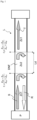
- FIG. 1 schematizes, as a reminder, the operating principle of a diagnostic method by reflectometry applied to a transmission line L presenting a non-clear fault DNF.
- the example described below corresponds to a time-domain reflectometry method.
- a reference signal S is injected into the transmission line at a point P.
- the reflected signal R is measured at the same point P (or at another point on the line).
- This signal propagates in the line and encounters, during its propagation, a first impedance discontinuity at the input of the non-clear fault DNF.
- the signal is reflected on this discontinuity with a reflection coefficient ⁇ 1 . If the characteristic impedance Z c 2 in the area of the non-clear fault DNF is lower than the characteristic impedance Z c 1 before the appearance of the fault, then the reflection coefficient ⁇ 1 is negative and results in a negative amplitude peak in the reflected signal R. In the opposite case, the reflection coefficient ⁇ 1 is positive and results in a positive amplitude peak in the reflected signal R.
- the transmitted part T of the incident signal S continues to propagate in the line and then encounters a second impedance discontinuity creating a second reflection of the incident signal with a reflection coefficient ⁇ 2 of opposite sign to the first reflection coefficient ⁇ 1 . If ⁇ 1 ⁇ 0 then ⁇ 2 > 0. If ⁇ 1 > 0 then ⁇ 2 ⁇ 0.
- the signature of the non-clear defect DNF is characterized by two successive peaks of inverted signs as shown in figure 2 .
- FIG. 2 represents a time reflectogram which corresponds either directly to the measurement of the reflected signal R, or to the cross-correlation between the reflected signal R and the signal injected into the cable S.
- the reflectogram can correspond directly to the measurement of the reflected signal R.
- the injected reference signal is a more complex signal, for example for methods of the MCTDR (Multi Carrier Time Domain Reflectometry) or OMTDR (Orthogonal Multi tone Time Domain Reflectometry) type, then the reflectogram is obtained by inter-correlating the reflected signal R and the injected signal S.
- MCTDR Multi Carrier Time Domain Reflectometry
- OMTDR Orthogonal Multi tone Time Domain Reflectometry
- Curve 201 corresponds to a pulse duration 2. ⁇ T much greater than the time taken for the signal to cross the non-clear fault DNF.
- Ld the time taken for the signal to cross the non-clear fault DNF.
- V the speed of signal propagation in the cable.
- Curve 202 corresponds to a pulse duration 2. ⁇ T much lower than the time taken for the signal to pass through the non-clear fault DNF.
- the signature 203 of the non-clear defect, in the reflectogram is always composed of the succession of a first peak and a second peak whose signs are reversed.
- the distance between the two peaks represents the length of the non-clear defect and their amplitude represents the severity of the non-clear defect. Indeed, the greater the variation in the characteristic impedance, the greater the amplitude of the non-clear defect signature in the reflectogram.
- the position of the DNF of the non-clear fault on the cable in other words its distance from the signal injection point P, can be directly obtained from the measurement, on the time domain reflectogram of the figure 2 , of the duration t DNF between the first amplitude peak noted on the reflectogram (at abscissa 0.5 in the example of the figure 2 ) and the amplitude peak 203 corresponding to the signature of the non-clear defect.
- FIG 3 represents a diagram of a system 300 for analyzing faults in a transmission line L, such as a cable or a wired network, implementing an OMTDR reflectometry method according to the prior art.
- Such a system 300 comprises a generator GEN of a digital reference signal.
- the signal is modulated via a phase modulator MOD according to a PSK modulation (phase shift keying).
- the PSK modulation is associated with a constellation of symbols CS.
- CS constellation of symbols
- the bits of the digital signal are randomly associated with the symbols of the PSK constellation.
- the modulated symbols are, for example, directly generated randomly to construct the modulated digital signal.
- the modulated signal is then synthesized in the time domain by means of an inverse discrete Fourier transform IDFT module.
- the synthesized signal is then analogically converted via a digital-to-analog converter DAC and is then injected into a point on the transmission line L by means of a coupler or any other device for injecting a signal into a line.
- the signal propagates along the line and is reflected on the singularities it contains. In the absence of a fault on the line, the signal is reflected on the end of the line if the termination of the line is not adapted. In the presence of a fault on the line, the signal is reflected on the impedance discontinuity caused by the fault.
- the reflected signal is back-propagated to a measurement point, which can be common to the injection point or different.
- the back-propagated signal is digitally converted by an analog-to-digital converter (ADC).
- a correlation COR is then performed between the measured digital signal and a copy of the digital signal generated before injection in order to produce a time domain reflectogram R(t) corresponding to the cross-correlation between the two signals.
- An OMTDR signal is based on OFDM technology and consists of using frequency subcarriers orthogonal to each other to form the test signal.
- Each amplitude, phase or frequency is used to encode a certain number of bits called a symbol.
- Binary data can be random or carry an information message.
- the amplitude and phase of an OFDM subcarrier are set by the binary data to be transmitted according to the chosen modulation type (M-PSK or M-QAM).
- An example of possible modulation for an OMTDR signal is M-PSK modulation because it has good autocorrelation properties due to the fact that the signal spectrum is flat.
- phase in question can only take a finite number of values.
- Each of the phase values represents a single binary number (also called a symbol), whose size (and therefore the amount of information transmitted) depends on the number of possible values for the phase.
- the binary numbers represented are all of the same size.
- the sequence of digital data to be sent: 000 001 011 010 101 corresponds to the sequence of symbols: 5 4 3 2 7 and to the sequence of phases 5 ⁇ /8,4 ⁇ /8, 3 ⁇ /8, 2 ⁇ /8, 7 ⁇ /8, according to an example implementation.
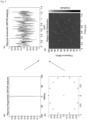
- An OMTDR signal with randomly chosen symbols (and therefore phases) generally has a poor ratio between peak power and average power PAPR. Moreover, such a signal is non-compressible in the time, frequency and time-frequency planes as illustrated in the figure 4 .
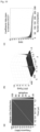
- the diagrams of the figure 4 represent different characteristics of a classic OMTDR signal modulated with 16-PSK modulation.
- figure 4c represents the time response of the signal and the figure 4d ) represents the distribution of the signal in the time-frequency plane, obtained by applying a Wigner-Ville transform to the signal.
- the signal is dense in the time-frequency plane, in other words it is not sparse. Such a signal is therefore not compressible.
- the invention aims to propose a new method for generating an OMTDR signal which makes it possible to construct a signal having a “chirp” shape while respecting the constraints of the adopted modulation.
- step 501 a digital signal in the form of a sequence of bits is generated.
- the digital signal is modulated by MPSK modulation by associating each digital symbol with an MPSK constellation point.
- Relation (1) has the effect of generating a signal having the structure of a “chirp” signal.
- the phases thus generated do not necessarily correspond to symbols of the chosen MPSK constellation.
- step 503 the phases generated in step 502 are rounded to the phases of the nearest MPSK constellation symbols.
- step 504 an inverse discrete Fourier transform step is applied to generate the OMTDR signal.
- the choice of the coefficient ⁇ makes it possible to structure the signal so that it has the form of a chirp signal.
- PAPR peak factor
- the coefficients ⁇ and ⁇ influence the peak factor reduction (PAPR) of the signal.
- the coefficient ⁇ is taken equal to ⁇ ⁇ N , the coefficient ⁇ is taken equal to 1 and the coefficient ⁇ is taken equal to 0.
- FIG 6 illustrates, on the phase diagram 601, the phases generated using relation (2) (step 502) and on the diagram 602, the symbols of the 16 PSK constellation obtained by rounding the phases of the diagram 601.
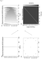
- figure 7 represents, on the same diagrams as in figure 4 , the characteristics of the OMTDR signal obtained with the first exemplary embodiment of the invention above.
- Table 1 shows examples of peak-to-average power ratio (PAPR) results for different PSK modulations and different numbers N of carriers, for a typical OMTDR signal.
- PAPR peak-to-average power ratio
- Table 2 represents the same results for an OMTDR signal obtained with the first exemplary embodiment of the invention.
- the invention is applicable to M-PSK phase modulations but also to M-QAM phase and amplitude modulations.
- the invention can be implemented by means of the device of the figure 1 , the OMTDR digital signal generator being replaced by a generator configured to perform the method of constructing a modified OMTDR signal according to the invention.
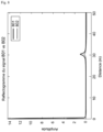
- FIG 8 represents two examples of reflectograms 801,802 respectively obtained with a prior art OMTDR system and an OMTDR system according to the first embodiment of the invention.
- an electrical fault is located at a distance of 30 m from the signal injection point.
- This fault is characterized by a peak 803 in the measured reflectogram. It can be seen on the figure 8 , that the improved OMTDR signal according to the invention makes it possible to amplify the peak 803 compared to the conventional OMTDR signal. Due to the improvement of the PAPR crest factor of the signal, the detection gain of the peak 803 is improved.
- the invention thus makes it possible to reduce the ratio between peak power and average power of an OMTDR signal in order to improve the precision of fault detection by analysis of a reflectogram.
- the invention also makes it possible to make an OMTDR signal sparse and compressible in the time-frequency domain.
- a signal is compressible in a domain if the moduli of its sorted coefficients in this domain decrease rapidly. Subsequently, we consider the domain of the DCCT (Discrete Cosine Chirp Transform) which is used as a basis for representing sparse signals as indicated in reference [1].
- DCCT Discrete Cosine Chirp Transform
- FIG. 9a illustrates the time-frequency representation of a classical OMTDR signal and shows that this signal is dense in the time-frequency plane.
- the figure 9c represents a curve of the moduli of the DCCT coefficients obtained at the figure 9b ) sorted in descending order We see that these coefficients have a decrease towards zero which is relatively slow. The distribution of the coefficients is spread over a wide range of values.
- FIG 10 illustrates the same diagrams as in figure 9 but this time for an OMTDR signal generated using the invention.
- the OMTDR signal generated using the invention is therefore compressible in the DCCT domain.
- Paper [1] describes in detail a method to reduce the sampling rate of an analog-to-digital converter in a reflectometry system when the signal used is compressible in the DCCT domain.
- FIG 11 represents a diagram of a reflectometry system 110 according to a second embodiment of the invention.
- the system 110 comprises a module 100 for generating an OMTDR signal according to the invention comprising at least one module 101 for generating phases and a module 102 for rounding the phases generated to the symbols closest to the chosen constellation.
- the system 110 then comprises a modulator MOD, an inverse Fourier transform module IDFT and a digital to analog converter DAC. These three elements are identical to those already described in figure 1 .
- System 110 differs from the reflectometry system described in figure 1 in that the analog-to-digital converter CAN is replaced by a compressed acquisition system ACQ which exploits the sparse nature of the generated OMTDR signal.
- the ACQ system includes a multiplier or mixer MUL whose function is to multiply the signal measured at the coupler output with a pseudo-random sequence of +/-1 values.
- the mixer MUL operates at a frequency fp which can be higher than the Nyquist frequency fs.
- the ACQ system then includes a low-pass filter FIL whose cutoff frequency depends on the desired compression factor, then an analog-to-digital converter CAN which operates at a sampling frequency fm which is lower than the frequency fp of the signal.
- a signal reconstruction RS module is used to reconstruct the signal before performing the COR intercorrelation with a copy of the generated signal.
- RS module Different signal reconstruction techniques can be implemented by the RS module.
- An example of a possible implementation is to apply a greedy algorithm to iteratively construct a sparse approximation of the signal.
- An example of a greedy algorithm is the "Orthogonal Matching Pursuit" algorithm described in reference [2].
Landscapes
- Physics & Mathematics (AREA)
- General Physics & Mathematics (AREA)
- Digital Transmission Methods That Use Modulated Carrier Waves (AREA)
- Cable Transmission Systems, Equalization Of Radio And Reduction Of Echo (AREA)
- Monitoring And Testing Of Transmission In General (AREA)
Claims (12)
- Verfahren zum Erzeugen eines Mehrträger-Reflektometriesignals, das in eine Übertragungsleitung eingespeist werden soll, um das Vorhandensein mindestens eines möglichen Fehlers in der Leitung zu identifizieren, wobei das Verfahren folgende Schritte umfasst:- Erzeugen eines digitalen, phasenmodulierten Mehrträgersignals in dem Frequenzbereich, durch:i. Erzeugen (501) eines digitalen Signals,ii. Phasenmodulieren (502) des digitalen Signals anhand einer Symbolkonstellation, wobei die Phase θk eines jeden modulierten Symbols anhand der folgenden Gleichung bestimmt wird: θk = ± (α * k2 ), wobei k der Index eines jeden Trägers des Signals ist und zwischen 1 und der Anzahl N der Träger des Signals variiert,iii. α ein Koeffizient ist, der in dem Intervall
 iv. Runden (503) der erzielten Phase θk auf die Phase des Symbols der nächstgelegenen Konstellation,- Umwandeln (504) des erzeugten Signals in den Zeitbereich.
 - Verfahren zum Erzeugen eines Mehrträger-Reflektometriesignals nach Anspruch 1, wobei die Phase θk eines jeden modulierten Symbols anhand der folgenden Gleichung bestimmt wird:

- Verfahren zum Erzeugen eines Mehrträger-Reflektometriesignals nach einem der vorhergehenden Ansprüche, wobei die Symbolkonstellation eine Konstellation aus einer Phasenmodulation PSK oder einer Phasen- und Amplitudenmodulation QAM ist.
- Verfahren zum Erzeugen eines Mehrträger-Reflektometriesignals nach einem der vorhergehenden Ansprüche, wobei das erzeugte Signal ein frequenzmoduliertes pseudoperiodisches Signal vom Typ "chirp" ist.
- Verfahren zum Erzeugen eines Mehrträger-Reflektometriesignals nach einem der vorhergehenden Ansprüche, ferner folgende Schritte umfassend:- Umwandeln des erzeugten digitalen Signals in ein analoges Signal,- Einspeisen des analogen Signals in eine Übertragungsleitung.
- Verfahren zum Identifizieren des Vorhandenseins von mindestens einem möglichen Fehler in einer Übertragungsleitung, wobei das Verfahren folgende Schritte umfasst:- Erzeugen eines Mehrträger-Reflektometriesignals und Einspeisen desselben in eine Übertragungsleitung mittels des Verfahrens nach Anspruch 5,- Erfassen und Analysieren des Echos des reflektierten Reflektometriesignals, um daraus eine Information bezüglich der Erkennung und/oder des Ortstands einer Impedanzdiskontinuität abzuleiten, die für mindestens einen Fehler charakteristisch ist.
- Verfahren zum Identifizieren des Vorhandenseins mindestens eines Fehlers nach Anspruch 6, wobei der Schritt des Analysierens des Echos des Reflektometriesignals folgende Teilschritte umfasst:- Berechnen der Kreuzkorrelation zwischen dem reflektierten Reflektometriesignal und dem in die Leitung eingespeisten Reflektometriesignal, um ein Reflektogramm zu erzielen,- Analysieren des Reflektogramms, um mindestens eine Amplitudenspitze zu identifizieren, die für das Vorhandensein eines Fehlers in der Leitung charakteristisch ist.
- Verfahren zum Identifizieren des Vorhandenseins mindestens eines Fehlers nach Anspruch 6, wobei der Schritt des Analysierens des Echos des Reflektometriesignals folgende Teilschritte umfasst:- Multiplizieren des erfassten Reflektometriesignals mit einer Pseudozufallssequenz,- Anwenden eines Tiefpassfilters auf das erzielte Signal,- Umwandeln des digital gefilterten Signals,- Rekonstruieren des Signals.
- Vorrichtung (300) zum Erzeugen eines Reflektometriesignals, das dazu bestimmt ist, in eine Übertragungsleitung eingespeist zu werden, um das Vorhandensein mindestens eines möglichen Fehlers in der Leitung zu identifizieren, wobei die Vorrichtung Mittel umfasst, die angepasst sind, um das Verfahren zum Erzeugen eines Reflektometriesignals nach einem der Ansprüche 1 bis 5 durchzuführen.
- Vorrichtung (110) zum Erzeugen eines Reflektometriesignals nach Anspruch 9, umfassend einen Reflektometriesignalgenerator, der zur Durchführung des Verfahrens zum Erzeugen eines Reflektometriesignals nach einem der Ansprüche 1 bis 5 konfiguriert ist, einen Digital-Analog-Wandler (DAC) und eine Kopplungsvorrichtung zum Einspeisen des analogen Reflektometriesignals in eine Übertragungsleitung.
- Computerprogramm, umfassend Anweisungen, welche die Vorrichtung nach einem der Anspruch 9 oder 10 dazu veranlassen, die Schritte des Verfahrens zum Erzeugen eines Reflektometriesignals nach einem der Ansprüche 1 bis 4 auszuführen.
- Prozessorlesbarer Aufzeichnungsträger, auf dem das Computerprogramm nach Anspruch 11 aufgezeichnet ist.
Applications Claiming Priority (1)
| Application Number | Priority Date | Filing Date | Title |
|---|---|---|---|
| FR2110241A FR3127581B1 (fr) | 2021-09-29 | 2021-09-29 | Méthode de génération d’un signal de réflectométrie multiporteuses ayant la forme d’un signal de type « chirp » |
Publications (2)
| Publication Number | Publication Date |
|---|---|
| EP4160230A1 EP4160230A1 (de) | 2023-04-05 |
| EP4160230B1 true EP4160230B1 (de) | 2025-01-22 |
Family
ID=80446706
Family Applications (1)
| Application Number | Title | Priority Date | Filing Date |
|---|---|---|---|
| EP22194390.5A Active EP4160230B1 (de) | 2021-09-29 | 2022-09-07 | Methode zur erzeugung eines mehrträger-reflektometriesignals, das die form eines chirp-signals hat |
Country Status (3)
| Country | Link |
|---|---|
| US (1) | US12140621B2 (de) |
| EP (1) | EP4160230B1 (de) |
| FR (1) | FR3127581B1 (de) |
Families Citing this family (2)
| Publication number | Priority date | Publication date | Assignee | Title |
|---|---|---|---|---|
| US12449468B2 (en) | 2023-06-26 | 2025-10-21 | International Business Machines Corporation | Enhanced resolution time-domain reflectometry |
| FR3159671A1 (fr) | 2024-02-23 | 2025-08-29 | Commissariat à l'Energie Atomique et aux Energies Alternatives | Méthode de caractérisation de défauts dans un câble par apprentissage automatique |
Family Cites Families (3)
| Publication number | Priority date | Publication date | Assignee | Title |
|---|---|---|---|---|
| NO341197B1 (no) * | 2012-10-24 | 2017-09-11 | Wirescan As | Fremgangsmåte og system for overvåkning av tilstanden til elektriske kabler |
| FR3060128B1 (fr) * | 2016-12-12 | 2019-03-15 | Commissariat A L'energie Atomique Et Aux Energies Alternatives | Systeme et procede de detection de defauts dans une ligne de transmission, par utilisation d'un signal complexe |
| FR3097971B1 (fr) | 2019-06-26 | 2021-06-04 | Commissariat Energie Atomique | Méthode de réduction de la puissance crête d’un signal de réflectométrie multi-porteuses |
-
2021
- 2021-09-29 FR FR2110241A patent/FR3127581B1/fr active Active
-
2022
- 2022-08-19 US US17/891,955 patent/US12140621B2/en active Active
- 2022-09-07 EP EP22194390.5A patent/EP4160230B1/de active Active
Also Published As
| Publication number | Publication date |
|---|---|
| FR3127581A1 (fr) | 2023-03-31 |
| US20230099415A1 (en) | 2023-03-30 |
| EP4160230A1 (de) | 2023-04-05 |
| US12140621B2 (en) | 2024-11-12 |
| FR3127581B1 (fr) | 2023-09-22 |
Similar Documents
| Publication | Publication Date | Title |
|---|---|---|
| EP3552032B1 (de) | System zur erkennung von defekten in einer übertragungsleitung unter verwendung eines komplexen signals | |
| EP3063546B1 (de) | Verfahren zur erzeugung eines mehrträger-reflektometriesignals zur implementierung in einem verteilten system | |
| EP4160230B1 (de) | Methode zur erzeugung eines mehrträger-reflektometriesignals, das die form eines chirp-signals hat | |
| EP3008479B1 (de) | Reflektometrieverfahren zur identifikation von schwachstellen eines kabels | |
| EP2277271B1 (de) | Mehrträger-reflektometrievorrichtung und verfahren zur online-diagnoseüberprüfung mindestens einer übertragungsleitung | |
| EP3304107B1 (de) | Reflektometrieverfahren und vorrichtung zur diagnose von kabeln im einsatz | |
| WO2013057131A1 (fr) | Procede de reflectometrie pour la detection de defauts non francs dans un cable electrique et systeme mettant en œuvre le procede | |
| WO2016050547A1 (fr) | Procede d'analyse d'un cable, basee sur une correlation auto-adaptative, pour la detection de defauts non francs | |
| EP1322970B1 (de) | Verfahren und vorrichtung zur leitungsdämpfungsmessung | |
| EP3990933A1 (de) | Verfahren zur reduzierung der spitzenleistung eines mehrträger-reflektometriesignals | |
| FR3117603A1 (fr) | Méthode et système de réflectométrie multi-porteuses avec prise en compte de l’atténuation et de la distorsion du signal | |
| FR3012617A1 (fr) | Methode de localisation de defauts electriques au sein d'un reseau de lignes de transmission et systeme associe | |
| FR3050849B1 (fr) | Procede et dispositif de reduction de bruit dans un signal module | |
| Gargouri et al. | Reflectometry architecture for enhanced fault localization based on low PAPR chirp-OMTDR | |
| FR3081561A1 (fr) | Systeme de reflectometrie binaire pour l'analyse de defauts dans une ligne de transmission | |
| EP3877773B1 (de) | System zur analyse von fehlern durch reflektometrie mit optimiertem dynamikbereich | |
| EP3646045B1 (de) | Reflektometrisches system zur fehleranalyse in einer übertragungsleitung | |
| FR3056058B1 (fr) | Procede de mesure normee de la modulation d'un signal radio module en amplitude et procede de filtrage dudit signal radio | |
| EP4147363B1 (de) | Verbessertes frequenzmoduliertes monostatisches dauerstrichradarsystem und zugehöriges kalibrierungsverfahren | |
| WO2019020448A1 (fr) | Systeme de reflectometrie pour l'analyse de defauts dans au moins une ligne de transmission, le systeme comprenant un correlateur complexe | |
| EP0031774B1 (de) | -16-stufiges MAMSK-Modulationsverfahren für digitales Datenübertragungssystem sowie Modulatoren und Demodulator dafür | |
| FR3159671A1 (fr) | Méthode de caractérisation de défauts dans un câble par apprentissage automatique | |
| WO2012028808A1 (fr) | Procédé et système de transmission de données par ondes porteuses non-linéaires | |
| FR2904428A1 (fr) | Procede pour ameliorer la qualite de la transposition en bande de base du signal recu par un radar a haute resolution comportant une chaine de reception analogique |
Legal Events
| Date | Code | Title | Description |
|---|---|---|---|
| PUAI | Public reference made under article 153(3) epc to a published international application that has entered the european phase |
Free format text: ORIGINAL CODE: 0009012 |
|
| STAA | Information on the status of an ep patent application or granted ep patent |
Free format text: STATUS: REQUEST FOR EXAMINATION WAS MADE |
|
| 17P | Request for examination filed |
Effective date: 20220907 |
|
| AK | Designated contracting states |
Kind code of ref document: A1 Designated state(s): AL AT BE BG CH CY CZ DE DK EE ES FI FR GB GR HR HU IE IS IT LI LT LU LV MC MK MT NL NO PL PT RO RS SE SI SK SM TR |
|
| RAP3 | Party data changed (applicant data changed or rights of an application transferred) |
Owner name: COMMISSARIAT A L'ENERGIE ATOMIQUE ET AUX ENERGIESALTERNATIVES |
|
| GRAP | Despatch of communication of intention to grant a patent |
Free format text: ORIGINAL CODE: EPIDOSNIGR1 |
|
| STAA | Information on the status of an ep patent application or granted ep patent |
Free format text: STATUS: GRANT OF PATENT IS INTENDED |
|
| GRAS | Grant fee paid |
Free format text: ORIGINAL CODE: EPIDOSNIGR3 |
|
| INTG | Intention to grant announced |
Effective date: 20241119 |
|
| GRAA | (expected) grant |
Free format text: ORIGINAL CODE: 0009210 |
|
| STAA | Information on the status of an ep patent application or granted ep patent |
Free format text: STATUS: THE PATENT HAS BEEN GRANTED |
|
| AK | Designated contracting states |
Kind code of ref document: B1 Designated state(s): AL AT BE BG CH CY CZ DE DK EE ES FI FR GB GR HR HU IE IS IT LI LT LU LV MC MK MT NL NO PL PT RO RS SE SI SK SM TR |
|
| REG | Reference to a national code |
Ref country code: GB Ref legal event code: FG4D Free format text: NOT ENGLISH |
|
| REG | Reference to a national code |
Ref country code: CH Ref legal event code: EP |
|
| REG | Reference to a national code |
Ref country code: IE Ref legal event code: FG4D Free format text: LANGUAGE OF EP DOCUMENT: FRENCH |
|
| REG | Reference to a national code |
Ref country code: DE Ref legal event code: R096 Ref document number: 602022009759 Country of ref document: DE |
|
| REG | Reference to a national code |
Ref country code: NL Ref legal event code: MP Effective date: 20250122 |
|
| PG25 | Lapsed in a contracting state [announced via postgrant information from national office to epo] |
Ref country code: NL Free format text: LAPSE BECAUSE OF FAILURE TO SUBMIT A TRANSLATION OF THE DESCRIPTION OR TO PAY THE FEE WITHIN THE PRESCRIBED TIME-LIMIT Effective date: 20250122 |
|
| PG25 | Lapsed in a contracting state [announced via postgrant information from national office to epo] |
Ref country code: RS Free format text: LAPSE BECAUSE OF FAILURE TO SUBMIT A TRANSLATION OF THE DESCRIPTION OR TO PAY THE FEE WITHIN THE PRESCRIBED TIME-LIMIT Effective date: 20250422 |
|
| PG25 | Lapsed in a contracting state [announced via postgrant information from national office to epo] |
Ref country code: FI Free format text: LAPSE BECAUSE OF FAILURE TO SUBMIT A TRANSLATION OF THE DESCRIPTION OR TO PAY THE FEE WITHIN THE PRESCRIBED TIME-LIMIT Effective date: 20250122 |
|
| PG25 | Lapsed in a contracting state [announced via postgrant information from national office to epo] |
Ref country code: PL Free format text: LAPSE BECAUSE OF FAILURE TO SUBMIT A TRANSLATION OF THE DESCRIPTION OR TO PAY THE FEE WITHIN THE PRESCRIBED TIME-LIMIT Effective date: 20250122 |
|
| PG25 | Lapsed in a contracting state [announced via postgrant information from national office to epo] |
Ref country code: ES Free format text: LAPSE BECAUSE OF FAILURE TO SUBMIT A TRANSLATION OF THE DESCRIPTION OR TO PAY THE FEE WITHIN THE PRESCRIBED TIME-LIMIT Effective date: 20250122 |
|
| REG | Reference to a national code |
Ref country code: LT Ref legal event code: MG9D |
|
| PG25 | Lapsed in a contracting state [announced via postgrant information from national office to epo] |
Ref country code: NO Free format text: LAPSE BECAUSE OF FAILURE TO SUBMIT A TRANSLATION OF THE DESCRIPTION OR TO PAY THE FEE WITHIN THE PRESCRIBED TIME-LIMIT Effective date: 20250422 Ref country code: IS Free format text: LAPSE BECAUSE OF FAILURE TO SUBMIT A TRANSLATION OF THE DESCRIPTION OR TO PAY THE FEE WITHIN THE PRESCRIBED TIME-LIMIT Effective date: 20250522 |
|
| REG | Reference to a national code |
Ref country code: AT Ref legal event code: MK05 Ref document number: 1761845 Country of ref document: AT Kind code of ref document: T Effective date: 20250122 |
|
| PG25 | Lapsed in a contracting state [announced via postgrant information from national office to epo] |
Ref country code: HR Free format text: LAPSE BECAUSE OF FAILURE TO SUBMIT A TRANSLATION OF THE DESCRIPTION OR TO PAY THE FEE WITHIN THE PRESCRIBED TIME-LIMIT Effective date: 20250122 |
|
| PG25 | Lapsed in a contracting state [announced via postgrant information from national office to epo] |
Ref country code: PT Free format text: LAPSE BECAUSE OF FAILURE TO SUBMIT A TRANSLATION OF THE DESCRIPTION OR TO PAY THE FEE WITHIN THE PRESCRIBED TIME-LIMIT Effective date: 20250522 Ref country code: LV Free format text: LAPSE BECAUSE OF FAILURE TO SUBMIT A TRANSLATION OF THE DESCRIPTION OR TO PAY THE FEE WITHIN THE PRESCRIBED TIME-LIMIT Effective date: 20250122 |
|
| PG25 | Lapsed in a contracting state [announced via postgrant information from national office to epo] |
Ref country code: BG Free format text: LAPSE BECAUSE OF FAILURE TO SUBMIT A TRANSLATION OF THE DESCRIPTION OR TO PAY THE FEE WITHIN THE PRESCRIBED TIME-LIMIT Effective date: 20250122 Ref country code: GR Free format text: LAPSE BECAUSE OF FAILURE TO SUBMIT A TRANSLATION OF THE DESCRIPTION OR TO PAY THE FEE WITHIN THE PRESCRIBED TIME-LIMIT Effective date: 20250423 |
|
| PG25 | Lapsed in a contracting state [announced via postgrant information from national office to epo] |
Ref country code: AT Free format text: LAPSE BECAUSE OF FAILURE TO SUBMIT A TRANSLATION OF THE DESCRIPTION OR TO PAY THE FEE WITHIN THE PRESCRIBED TIME-LIMIT Effective date: 20250122 |
|
| PG25 | Lapsed in a contracting state [announced via postgrant information from national office to epo] |
Ref country code: SE Free format text: LAPSE BECAUSE OF FAILURE TO SUBMIT A TRANSLATION OF THE DESCRIPTION OR TO PAY THE FEE WITHIN THE PRESCRIBED TIME-LIMIT Effective date: 20250122 |
|
| PG25 | Lapsed in a contracting state [announced via postgrant information from national office to epo] |
Ref country code: SM Free format text: LAPSE BECAUSE OF FAILURE TO SUBMIT A TRANSLATION OF THE DESCRIPTION OR TO PAY THE FEE WITHIN THE PRESCRIBED TIME-LIMIT Effective date: 20250122 |
|
| PG25 | Lapsed in a contracting state [announced via postgrant information from national office to epo] |
Ref country code: DK Free format text: LAPSE BECAUSE OF FAILURE TO SUBMIT A TRANSLATION OF THE DESCRIPTION OR TO PAY THE FEE WITHIN THE PRESCRIBED TIME-LIMIT Effective date: 20250122 |
|
| PGFP | Annual fee paid to national office [announced via postgrant information from national office to epo] |
Ref country code: DE Payment date: 20250919 Year of fee payment: 4 |
|
| PG25 | Lapsed in a contracting state [announced via postgrant information from national office to epo] |
Ref country code: IT Free format text: LAPSE BECAUSE OF FAILURE TO SUBMIT A TRANSLATION OF THE DESCRIPTION OR TO PAY THE FEE WITHIN THE PRESCRIBED TIME-LIMIT Effective date: 20250122 |
|
| PGFP | Annual fee paid to national office [announced via postgrant information from national office to epo] |
Ref country code: FR Payment date: 20250923 Year of fee payment: 4 |
|
| PG25 | Lapsed in a contracting state [announced via postgrant information from national office to epo] |
Ref country code: EE Free format text: LAPSE BECAUSE OF FAILURE TO SUBMIT A TRANSLATION OF THE DESCRIPTION OR TO PAY THE FEE WITHIN THE PRESCRIBED TIME-LIMIT Effective date: 20250122 Ref country code: CZ Free format text: LAPSE BECAUSE OF FAILURE TO SUBMIT A TRANSLATION OF THE DESCRIPTION OR TO PAY THE FEE WITHIN THE PRESCRIBED TIME-LIMIT Effective date: 20250122 |
|
| REG | Reference to a national code |
Ref country code: DE Ref legal event code: R097 Ref document number: 602022009759 Country of ref document: DE |
|
| PG25 | Lapsed in a contracting state [announced via postgrant information from national office to epo] |
Ref country code: RO Free format text: LAPSE BECAUSE OF FAILURE TO SUBMIT A TRANSLATION OF THE DESCRIPTION OR TO PAY THE FEE WITHIN THE PRESCRIBED TIME-LIMIT Effective date: 20250122 |
|
| PG25 | Lapsed in a contracting state [announced via postgrant information from national office to epo] |
Ref country code: SK Free format text: LAPSE BECAUSE OF FAILURE TO SUBMIT A TRANSLATION OF THE DESCRIPTION OR TO PAY THE FEE WITHIN THE PRESCRIBED TIME-LIMIT Effective date: 20250122 |
|
| PLBE | No opposition filed within time limit |
Free format text: ORIGINAL CODE: 0009261 |
|
| STAA | Information on the status of an ep patent application or granted ep patent |
Free format text: STATUS: NO OPPOSITION FILED WITHIN TIME LIMIT |
|
| 26N | No opposition filed |
Effective date: 20251023 |