EP3552010B1 - Système de commande de la température d'un système chromatographique - Google Patents
Système de commande de la température d'un système chromatographique Download PDFInfo
- Publication number
- EP3552010B1 EP3552010B1 EP18757887.7A EP18757887A EP3552010B1 EP 3552010 B1 EP3552010 B1 EP 3552010B1 EP 18757887 A EP18757887 A EP 18757887A EP 3552010 B1 EP3552010 B1 EP 3552010B1
- Authority
- EP
- European Patent Office
- Prior art keywords
- temperature
- component
- chromatographic
- heating element
- electrically
- Prior art date
- Legal status (The legal status is an assumption and is not a legal conclusion. Google has not performed a legal analysis and makes no representation as to the accuracy of the status listed.)
- Active
Links
Images
Classifications
-
- G—PHYSICS
- G01—MEASURING; TESTING
- G01N—INVESTIGATING OR ANALYSING MATERIALS BY DETERMINING THEIR CHEMICAL OR PHYSICAL PROPERTIES
- G01N30/00—Investigating or analysing materials by separation into components using adsorption, absorption or similar phenomena or using ion-exchange, e.g. chromatography or field flow fractionation
- G01N30/02—Column chromatography
- G01N30/26—Conditioning of the fluid carrier; Flow patterns
- G01N30/28—Control of physical parameters of the fluid carrier
- G01N30/30—Control of physical parameters of the fluid carrier of temperature
- G01N2030/3053—Control of physical parameters of the fluid carrier of temperature using resistive heating
- G01N2030/3069—Control of physical parameters of the fluid carrier of temperature using resistive heating electrical resistance used to determine control temperature
-
- G—PHYSICS
- G01—MEASURING; TESTING
- G01N—INVESTIGATING OR ANALYSING MATERIALS BY DETERMINING THEIR CHEMICAL OR PHYSICAL PROPERTIES
- G01N30/00—Investigating or analysing materials by separation into components using adsorption, absorption or similar phenomena or using ion-exchange, e.g. chromatography or field flow fractionation
- G01N30/02—Column chromatography
- G01N30/26—Conditioning of the fluid carrier; Flow patterns
- G01N30/28—Control of physical parameters of the fluid carrier
- G01N30/30—Control of physical parameters of the fluid carrier of temperature
- G01N2030/3076—Control of physical parameters of the fluid carrier of temperature using specially adapted T(t) profile
-
- G—PHYSICS
- G01—MEASURING; TESTING
- G01N—INVESTIGATING OR ANALYSING MATERIALS BY DETERMINING THEIR CHEMICAL OR PHYSICAL PROPERTIES
- G01N30/00—Investigating or analysing materials by separation into components using adsorption, absorption or similar phenomena or using ion-exchange, e.g. chromatography or field flow fractionation
- G01N30/02—Column chromatography
- G01N30/26—Conditioning of the fluid carrier; Flow patterns
- G01N30/28—Control of physical parameters of the fluid carrier
- G01N30/30—Control of physical parameters of the fluid carrier of temperature
- G01N2030/3084—Control of physical parameters of the fluid carrier of temperature ovens
Definitions
- An adaptive temperature controller for use with any electrically-conductive material is disclosed.
- the chromatographic column is heated according to a temperature profile, which may profile multiple temperature settings at various times during operation. Temperature is known to substantially alter the effectiveness of the column, affecting efficiency and repeatability of the separation.
- the columns are associated with necessary related equipment, such as the sample injector, valves, transport lines, and detectors. As maintaining temperature of the sample and the resulting separation is of importance, it is known in the art to position the column in an oven and to position the remaining components in the oven or abutting its external walls. These column ovens, however, tend to be substantial in volume, consuming substantial space, and heavy, precluding transport.
- the balance of the components may be positioned in a static air bath, encapsulated in their own air baths, resulting in the consumption of substantial volumes of laboratory space.
- various temperature controllers and heating apparatus It is well known to provide a source of heat that is easily controlled. Most often heat is transferred from a conductive element.
- the temperature of such conductive element was monitored by a separate device, often a Resistance Temperature Detector (RTD).
- RTD Resistance Temperature Detector
- the adaptive temperature controller disclosed herein includes a device for measuring electrical resistance, an electrically-conductive material, and a power supply.
- the controller determines the resistance of the electrically-conductive material at one or more predetermined temperatures and is able to determine the corresponding resistance of the electrically-conductive material at other temperatures within a temperature range and to apply the voltage or current necessary to obtain such resistances.
- the predetermined (calibration) temperatures of the electrically-conductive material may be determined by using a temperature sensor or by approximation based on ambient air temperature. As a result, the voltage or power may be instantly varied to produce near infinite control over material temperature.
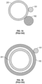
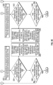
- temperature controllers are known where a conductive element 102 and a sensor 101 were placed in proximity to or about one component 201 of a system 200 to respectively heat and monitor the temperature of that single component 201. It is well known to provide a source of heat that is easily controlled. Most often heat is transferred from a conductive element 102 to be subsequently distributed to component 201.
- the conductive element 102 may be placed adjacent ( FIG 1a ) or surrounding ( FIG 1b ) element 301.
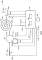
- the chromatographic system 200 may include a plurality of components 201a, 201b, 201c, 201d, 201e, such as transfer lines 204, injection valves 206, sample loops 208, columns 210 and detectors 212.
- a valve 206 may be connected to the output of the sample loop 208 and the input of the column 210.
- the column 210 may be a coiled bundle.
- a valve 206 may be connected to the input and output of the sample loop 208 and the column 210 and to the input of a detector 212.
- the valve may also be connected to the output from the detector 212.
- Indirect heating therefore may be most effective for components 201a, 201b, 201c, 201d, 201e wherein the component body is not sufficiently electrically conductive, such as a valve 206, or where electrical interference is undesirable, such as in a detector 212.
- a bundled column 210 may include within the bundle one or more nickel wires.
- the temperature of the component 201a, 201b, 201c, 201d, 201e, the rate of heating, and the duration of heating at any temperatures are controlled by temperature controller 250.
- the system 200 may include a combination of direct and indirect heating.
- the temperature of the component 204, 206, 208, 210, and 212 may be calculated based on resistance, may be adjusted based on signals from a temperature-measuring device such as a thermocouple, or may be controlled based on a combination of calculation and sensor readings.
- a temperature-measuring device such as a thermocouple
- Such devices can be selected to further the goal of small, portable chromatographic analysis.
- the selection of small K-type thermocouple allows for rapid temperature. Indirect heating using nickel wire may reduce weight.
- Control of the temperature of the heating element 202a, 202b, 202c, 202d, and 202e associated with the component 204, 206, 208, 210, and 212 by determination of resistance by a resistance-sensing circuit 248 and application of power, current or voltage may provide several advantages, particularly in reducing the mass of the chromatographic system 200, as components such as separate heater cartridges intermediate the heating element and the temperature controller, can be eliminated. Moreover, localized areas of increased or decreased temperature may be avoided as the heat flux is distributed over a large area, rather than emanating from a particular location associated with the heater cartridge. Further, the temperature may be more uniformly distributed as the surface area indirectly heated, or the surface area directly heated, is increased to provide an even distribution along its length rather than from one point associated with a cartridge heater.
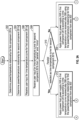
- the temperature controller 250 may be calibrated for it.
- the resistance of the heating element 202a, 202b, 202c, 202d, and 202e is not immediately known, but its normalized resistance characteristic is known, such as in the case of an unknown length or diameter of nickel wire
- the temperature controller 250 may be calibrated for use with a heating element 202a, 202b, 202c, 202d, and 202e by measurement of the resistance of the heating element 202a, 202b, 202c, 202d, and 202e at one or more known temperatures from the resistance sensing circuit 248.
- a uniform temperature throughout a heating element 202a, 202b, 202c, 202d, and 202e may be obtained by heating the heating element 202a, 202b, 202c, 202d, and 202e in an oven.
- the scale factor derived by dividing the measured resistance value of the heating element 202a, 202b, 202c, 202d, and 202e by the normalized resistance value of the material from which the heating element 202a, 202b, 202c, 202d, and 202e is composed at the reference temperature may then be applied to the normalized resistance characteristic to determine the resistance of the heating element 202a, 202b, 202c, 202d, and 202e at any particular temperature.
- the temperature controller 250 may control the heating element 202a, 202b, 202c, 202d, and 202e to provide varying temperatures to a particular device or over a corresponding period of time, such as stepped or ramped temperature increases.
- the heating element 202a is therefore a first electrically-controlled heating element 202a associated with the first chromatographic component 201a while the heating element 202b is a second electrically-controlled heating element 202b associated with the second chromatographic component 201b.
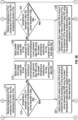
- the concurrent control of temperature of the various components 201a, 201b, 201c, 201d, 201e provides substantive advantages.
- the temperature controller 250 may provide a common temperature across the various components 201a, 201b, 201c, 201d, 201e or may be set to track the temperature of an upstream device. In a common temperature setting, the temperature controller 250 ensures each component 201a, 201b, 201c, 201d, 201e is at a common temperature setting during operation, although the temperature of each component 201a, 201b, 201c, 201d, 201e may fluctuate independently according to its own heating characteristics.
- the temperature controller 250 adjusts the power output from a power supply 258 to the first component 201a to match the time/temperature profile for the first component 201a received in step 306.
- a fan 218 or other cooling device is associated with the temperature controller with the heat transfer rate is insufficient to adequately reduce the temperature of the first component 201a.
- the temperature of the first component 201a is maintained within 0.1°C for isothermal, within 1.0°C for temperature programming, or 10% of the intended temperature from the actual temperature identified in the previous cycle. This adjustment may be controlled by the first processor 252.
- the temperature controller 250 than proceeds to step 320.
- the temperature controller 250 applies power from power supply 258 to the first component 201a according to time-temperature curve received in step 306 using the power/temperature relationship for the first component 201a from step 302.
- the temperature of the second component 201b is thus targeted to match, for the appropriate cycle, the actual temperature of the first component 201a.
- the temperature controller 250 includes a second electrically-controlled heating element output wherein the temperature controller 250, such as within a first processor 252 or a second processor 254, has a second power supply control for controlling the second output from the power supply 258 to the second electrically-controlled heating element output.
- the temperature controller 250, and particularly the first processor 252 or second processor 254 is adapted to alter the second output from the power supply 258 so a second actual time-temperature curve approaches the first actual time-temperature curve of step 332.
Landscapes
- General Health & Medical Sciences (AREA)
- Life Sciences & Earth Sciences (AREA)
- Chemical & Material Sciences (AREA)
- Analytical Chemistry (AREA)
- Biochemistry (AREA)
- Immunology (AREA)
- General Physics & Mathematics (AREA)
- Health & Medical Sciences (AREA)
- Pathology (AREA)
- Physics & Mathematics (AREA)
- Investigating Or Analyzing Materials Using Thermal Means (AREA)
- Control Of Temperature (AREA)
- Treatment Of Liquids With Adsorbents In General (AREA)
- Control Of Resistance Heating (AREA)
Claims (4)
- Système de commande de température chromatographique, comprenant :un premier composant chromatographique (201a) sélectionné dans le groupe de composants chromatographiques constitué d'une ligne de transport (204), d'une boucle d'échantillon (208) et d'une colonne (210) ;chacun du premier groupe de composants chromatographiques comportant un matériau électriquement conducteur (114) ;un second composant chromatographique (201b) sélectionné parmi un second groupe de composants chromatographiques constitué d'une vanne (206) et d'un détecteur (212) ;un premier élément chauffant à commande électrique (202a) associé au matériau électriquement conducteur du premier composant chromatographique (201a) ;un second élément chauffant à commande électrique (202b) associé au second composant chromatographique (201b) ;un premier capteur de température (214a) associé au premier composant chromatographique (201a), le premier capteur de température (214a) générant un premier signal de capteur de température sur la base de la température du premier composant chromatographique (201a) ;un second capteur de température (214b) associé au second composant chromatographique (201b),le second capteur de température (214b) générant un second signal de capteur de température sur la base de la température du second composant chromatographique (201b), une alimentation électrique (258) ;un dispositif de commande de température, le dispositif de commande de température comportant un processeur (252), une première sortie d'élément chauffant à commande électrique, une seconde sortie d'élément chauffant à commande électrique, une première entrée de capteur de température, une seconde entrée de capteur de température ;le processeur (252) est adapté pour recevoir le premier signal de capteur de température au niveau de la première entrée de capteur de température et pour construire un premier profil temps-température réel pour le premier composant chromatographique (201a) ;le processeur (252) est adapté pour recevoir le second signal de capteur de température au niveau de la seconde entrée de capteur de température et pour construire un second profil temps-température réel pour le second composant chromatographique (201b) ;le processeur (252) est adapté pour recevoir un premier profil temps-température pour le premier composant chromatographique (201a) ;le processeur (252) est adapté pour recevoir un second profil temps-température pour le second composant chromatographique (201b) sélectionné dans le groupe du premier profil temps-température et du premier profil temps-température réel du premier composant chromatographique (201a) ;le processeur (252) comportant une première commande d'alimentation électrique pour commander une première sortie del'alimentation électrique (258) vers la sortie de premier élément chauffant à commande électrique ;le processeur (252) comportant une deuxième commande d'alimentation électrique pour commander une deuxième sortie de l'alimentation électrique (258) vers la seconde sortie d'élément chauffant à commande électrique ; le processeur (252) est adapté pour comparer le premier profil temps-température réel au premier profil temps-température et modifier la première sortie de l'alimentation électrique (258) afin que le premier profil temps-température réel se rapproche du premier profil temps-température ; et le processeur (252) est adapté pour comparer le second profil temps-température réel au second profil temps-température et modifier la deuxième sortie de l'alimentation électrique (258) afin que le second profil temps-température réel se rapproche du second profil temps-température.
- Système chromatographique de la revendication 1, l'un du premier élément chauffant à commande électrique (202a) et du second élément chauffant à commande électrique (202b) étant un fil composé de nickel.
- Système chromatographique de la revendication 1, l'un du premier élément chauffant à commande électrique (202a) et du second élément chauffant à commande électrique (202b) étant un fil composé d'un alliage de nickel.
- Système chromatographique de la revendication 1, comprenant en outre un ventilateur (218) pour induire un flux d'air autour de l'un du premier composant et du second composant, ledit processeur (252) comportant une troisième commande d'alimentation pour commander une troisième sortie de l'alimentation électrique (258) vers le ventilateur (218).
Priority Applications (1)
| Application Number | Priority Date | Filing Date | Title |
|---|---|---|---|
| EP24177633.5A EP4417284A3 (fr) | 2017-02-24 | 2018-02-26 | Système de régulation de température de système chromatographique |
Applications Claiming Priority (2)
| Application Number | Priority Date | Filing Date | Title |
|---|---|---|---|
| US15/441,372 US10324069B2 (en) | 2017-02-24 | 2017-02-24 | Chromatographic system temperature control system |
| PCT/US2018/019695 WO2018157049A1 (fr) | 2017-02-24 | 2018-02-26 | Système de commande de la température d'un système chromatographique |
Related Child Applications (2)
| Application Number | Title | Priority Date | Filing Date |
|---|---|---|---|
| EP24177633.5A Division-Into EP4417284A3 (fr) | 2017-02-24 | 2018-02-26 | Système de régulation de température de système chromatographique |
| EP24177633.5A Division EP4417284A3 (fr) | 2017-02-24 | 2018-02-26 | Système de régulation de température de système chromatographique |
Publications (4)
| Publication Number | Publication Date |
|---|---|
| EP3552010A1 EP3552010A1 (fr) | 2019-10-16 |
| EP3552010A4 EP3552010A4 (fr) | 2019-12-25 |
| EP3552010B1 true EP3552010B1 (fr) | 2024-07-10 |
| EP3552010C0 EP3552010C0 (fr) | 2024-07-10 |
Family
ID=63246671
Family Applications (2)
| Application Number | Title | Priority Date | Filing Date |
|---|---|---|---|
| EP24177633.5A Pending EP4417284A3 (fr) | 2017-02-24 | 2018-02-26 | Système de régulation de température de système chromatographique |
| EP18757887.7A Active EP3552010B1 (fr) | 2017-02-24 | 2018-02-26 | Système de commande de la température d'un système chromatographique |
Family Applications Before (1)
| Application Number | Title | Priority Date | Filing Date |
|---|---|---|---|
| EP24177633.5A Pending EP4417284A3 (fr) | 2017-02-24 | 2018-02-26 | Système de régulation de température de système chromatographique |
Country Status (8)
| Country | Link |
|---|---|
| US (4) | US10324069B2 (fr) |
| EP (2) | EP4417284A3 (fr) |
| JP (1) | JP2020507756A (fr) |
| KR (1) | KR102285106B1 (fr) |
| CN (1) | CN110546497A (fr) |
| AU (1) | AU2018225761A1 (fr) |
| CA (1) | CA3049471C (fr) |
| WO (1) | WO2018157049A1 (fr) |
Families Citing this family (2)
| Publication number | Priority date | Publication date | Assignee | Title |
|---|---|---|---|---|
| US10324069B2 (en) * | 2017-02-24 | 2019-06-18 | Valco Instruments Company, L.P. | Chromatographic system temperature control system |
| GB2596109B (en) * | 2020-06-18 | 2024-09-18 | Agilent Technologies Inc | Thermally impacting fluid and sample separation unit independently |
Family Cites Families (42)
| Publication number | Priority date | Publication date | Assignee | Title |
|---|---|---|---|---|
| US4072846A (en) * | 1976-03-01 | 1978-02-07 | Varian Associates, Inc. | Control system for a chromatography apparatus oven door |
| JPS5349492A (en) * | 1976-10-18 | 1978-05-04 | Hitachi Ltd | Gas chromatograph |
| US4569876A (en) * | 1984-08-08 | 1986-02-11 | Nec Corporation | Multi-layered substrate having a fine wiring structure for LSI or VLSI circuits |
| US5028246A (en) | 1986-02-03 | 1991-07-02 | Ensign-Bickford Optical Technologies, Inc. | Methods of making optical waveguides |
| US4923486A (en) * | 1988-12-22 | 1990-05-08 | University Of Dayton | Gas chromatography methods and apparatus |
| US5028243A (en) * | 1988-12-22 | 1991-07-02 | University Of Dayton | Gas chromatography methods and apparatus |
| US4948389A (en) * | 1989-05-22 | 1990-08-14 | Hewlett-Packard Company | Gas chromatograph having cyro blast coolings |
| WO1991000131A1 (fr) | 1989-06-27 | 1991-01-10 | University Of Florida | Mesure du chauffage direct par resistance et de la temperature de colonnes capillaires revetues de metal dans la chromatographie en phase gazeuse, et techniques de separation s'y rapportant |
| US5105067A (en) | 1989-09-08 | 1992-04-14 | Environwear, Inc. | Electronic control system and method for cold weather garment |
| ES2054387T3 (es) * | 1990-04-07 | 1994-08-01 | Eberhard Gerstel | Procedimiento y dispositivo para la separacion gascromatografica. |
| US5553622A (en) | 1991-01-29 | 1996-09-10 | Mckown; Russell C. | System and method for controlling the temperature of a catheter-mounted heater |
| US5135549A (en) * | 1991-01-30 | 1992-08-04 | The Board Of Trustees Of Southern Illinois University | Chromatographic technique and apparatus |
| US5544276A (en) * | 1993-11-30 | 1996-08-06 | Microsensors Technology, Inc. | Miniature gas chromatograph with heated gas inlet fitting, heated tubing, and heated microvalve assembly |
| DE69637079T2 (de) * | 1995-10-16 | 2008-01-24 | Thermo Orion Inc., Beverly | Hochgeschwindigkeitschromatographie |
| US5793022A (en) | 1996-09-12 | 1998-08-11 | Applied Materials, Inc. | Adaptive temperture controller and method of operation |
| US6519546B1 (en) | 1996-11-07 | 2003-02-11 | Rosemount Inc. | Auto correcting temperature transmitter with resistance based sensor |
| US6209386B1 (en) * | 1998-06-05 | 2001-04-03 | Rvm Scientific, Inc. | Electrically insulated gas chromatograph assembly and method of fabricating same |
| US6137669A (en) | 1998-10-28 | 2000-10-24 | Chiang; Justin N. | Sensor |
| US6252209B1 (en) | 1999-01-21 | 2001-06-26 | Andigilog, Inc. | Adaptive temperature control circuit with PWM output |
| IT1313967B1 (it) * | 1999-12-27 | 2002-09-26 | Thermoquest Italia Spa | Sistema e metodo per controllare la temperatura di una colonna percromatografia. |
| US7257987B2 (en) * | 2000-01-25 | 2007-08-21 | State Of Oregon Acting By And Through The State Board Of Higher Education On Behalf Of Portland State University | Method and apparatus for sample analysis |
| JP3843880B2 (ja) | 2001-05-31 | 2006-11-08 | 株式会社デンソー | ガス濃度センサのヒータ制御装置 |
| US7495455B2 (en) * | 2002-06-28 | 2009-02-24 | Solar Wide Industrial Limited | Stud sensing device |
| JP4188206B2 (ja) * | 2003-11-04 | 2008-11-26 | 株式会社日立ハイテクノロジーズ | 液体クロマトグラフ用カラムオーブン |
| US7193187B2 (en) | 2004-02-09 | 2007-03-20 | Advanced Technology Materials, Inc. | Feedback control system and method for maintaining constant resistance operation of electrically heated elements |
| US7293449B2 (en) * | 2004-03-05 | 2007-11-13 | The Regents Of The University Of Michigan | Thermal modulation for gas chromatography |
| US7256371B2 (en) * | 2004-03-22 | 2007-08-14 | Integrated Electronic Solutions Pty Ltd. | Temperature control method for positive temperature coefficient type heating element |
| EP1994537B1 (fr) * | 2006-03-13 | 2012-09-19 | Valco Instruments Company, L.P. | Unité de commande de la température adaptative |
| US8642931B2 (en) | 2006-03-13 | 2014-02-04 | Valco Instruments Company, L.P. | Adaptive temperature controller |
| GB2446414A (en) | 2007-02-06 | 2008-08-13 | Thorn Security | A Detector |
| JP2009121937A (ja) * | 2007-11-14 | 2009-06-04 | Fuji Xerox Co Ltd | クロマトグラフ装置及びセンサ |
| DE102008059751A1 (de) | 2008-12-01 | 2010-06-02 | Voss Automotive Gmbh | Verfahren und Heizsystem zum Beheizen eines Fluid-Leitungssystems insbesondere in einem Kraftfahrzeug |
| US8999245B2 (en) * | 2009-07-07 | 2015-04-07 | Tricorn Tech Corporation | Cascaded gas chromatographs (CGCs) with individual temperature control and gas analysis systems using same |
| JP5644187B2 (ja) * | 2010-05-31 | 2014-12-24 | 株式会社島津製作所 | カラムオーブン |
| KR101167486B1 (ko) | 2010-07-08 | 2012-07-27 | 삼성전기주식회사 | 고온 크로마토그래피 장치 및 그 방법 |
| US10302605B2 (en) * | 2011-02-07 | 2019-05-28 | Agilent Technologies, Inc. | Column assembly for a gas chromatograph |
| KR101596131B1 (ko) | 2014-04-25 | 2016-02-22 | 한국과학기술원 | 소수성 표면을 이용한 칩 패키징 방법 및 칩 패키지 |
| US10145823B2 (en) * | 2014-09-13 | 2018-12-04 | Agilent Technologies, Inc. | Gas chromatography (GC) column heater control using multiple temperature sensors |
| EP3070469A1 (fr) * | 2015-03-18 | 2016-09-21 | Université de Genève | Système de chauffage de solvant pour des séparations de préparation |
| GB201522435D0 (en) * | 2015-12-18 | 2016-02-03 | Thermo Fisher Scient Bremen | Heated transfer line |
| US10324069B2 (en) * | 2017-02-24 | 2019-06-18 | Valco Instruments Company, L.P. | Chromatographic system temperature control system |
| US9927406B1 (en) * | 2017-06-02 | 2018-03-27 | Gc Ovens Inc. | Fluidless column oven for gas chromatography system |
-
2017
- 2017-02-24 US US15/441,372 patent/US10324069B2/en active Active
-
2018
- 2018-02-26 AU AU2018225761A patent/AU2018225761A1/en not_active Abandoned
- 2018-02-26 JP JP2019541096A patent/JP2020507756A/ja active Pending
- 2018-02-26 EP EP24177633.5A patent/EP4417284A3/fr active Pending
- 2018-02-26 KR KR1020197022905A patent/KR102285106B1/ko active Active
- 2018-02-26 WO PCT/US2018/019695 patent/WO2018157049A1/fr not_active Ceased
- 2018-02-26 CA CA3049471A patent/CA3049471C/fr active Active
- 2018-02-26 EP EP18757887.7A patent/EP3552010B1/fr active Active
- 2018-02-26 CN CN201880013782.9A patent/CN110546497A/zh active Pending
-
2019
- 2019-05-14 US US16/411,397 patent/US10481136B2/en active Active
- 2019-05-14 US US16/411,379 patent/US10502721B2/en active Active
- 2019-07-02 US US16/460,506 patent/US10481137B2/en active Active
Also Published As
| Publication number | Publication date |
|---|---|
| WO2018157049A1 (fr) | 2018-08-30 |
| US10324069B2 (en) | 2019-06-18 |
| US20190265208A1 (en) | 2019-08-29 |
| KR102285106B1 (ko) | 2021-08-02 |
| KR20190104373A (ko) | 2019-09-09 |
| CA3049471A1 (fr) | 2018-08-30 |
| AU2018225761A1 (en) | 2019-08-15 |
| JP2020507756A (ja) | 2020-03-12 |
| US20180246074A1 (en) | 2018-08-30 |
| EP4417284A3 (fr) | 2025-01-08 |
| EP3552010A4 (fr) | 2019-12-25 |
| EP4417284A2 (fr) | 2024-08-21 |
| EP3552010C0 (fr) | 2024-07-10 |
| CA3049471C (fr) | 2022-06-28 |
| US10481136B2 (en) | 2019-11-19 |
| US20190323999A1 (en) | 2019-10-24 |
| US10502721B2 (en) | 2019-12-10 |
| US20190265209A1 (en) | 2019-08-29 |
| US10481137B2 (en) | 2019-11-19 |
| EP3552010A1 (fr) | 2019-10-16 |
| CN110546497A (zh) | 2019-12-06 |
Similar Documents
| Publication | Publication Date | Title |
|---|---|---|
| US7442902B2 (en) | Adaptive temperature controller | |
| US8642931B2 (en) | Adaptive temperature controller | |
| EP3658867B1 (fr) | Système de capteur et ensemble capteur-dispositif de chauffage intégré pour mesurer et commander les performances d'un système de chauffage | |
| US10481137B2 (en) | Chromatographic system temperature control system | |
| HK40114918A (en) | Chromatographic system temperature control system | |
| HK1131851B (en) | Adaptive temperature controller |
Legal Events
| Date | Code | Title | Description |
|---|---|---|---|
| STAA | Information on the status of an ep patent application or granted ep patent |
Free format text: STATUS: THE INTERNATIONAL PUBLICATION HAS BEEN MADE |
|
| PUAI | Public reference made under article 153(3) epc to a published international application that has entered the european phase |
Free format text: ORIGINAL CODE: 0009012 |
|
| STAA | Information on the status of an ep patent application or granted ep patent |
Free format text: STATUS: REQUEST FOR EXAMINATION WAS MADE |
|
| 17P | Request for examination filed |
Effective date: 20190710 |
|
| AK | Designated contracting states |
Kind code of ref document: A1 Designated state(s): AL AT BE BG CH CY CZ DE DK EE ES FI FR GB GR HR HU IE IS IT LI LT LU LV MC MK MT NL NO PL PT RO RS SE SI SK SM TR |
|
| AX | Request for extension of the european patent |
Extension state: BA ME |
|
| A4 | Supplementary search report drawn up and despatched |
Effective date: 20191126 |
|
| RIC1 | Information provided on ipc code assigned before grant |
Ipc: G01N 30/30 20060101AFI20191120BHEP Ipc: B01D 15/16 20060101ALI20191120BHEP Ipc: G01N 30/54 20060101ALI20191120BHEP |
|
| DAV | Request for validation of the european patent (deleted) | ||
| DAX | Request for extension of the european patent (deleted) | ||
| RIN1 | Information on inventor provided before grant (corrected) |
Inventor name: SIMPSON, ROBERT Inventor name: CAI, HUAMIN Inventor name: HOCHMAN, MATIAS Inventor name: BISHOP, CHRIS Inventor name: COWLES, CHRIS, S. Inventor name: ASHWORTH, DALE Inventor name: STEARNS, STANLEY, D. Inventor name: DAILEY, DOUGLAS |
|
| RAP3 | Party data changed (applicant data changed or rights of an application transferred) |
Owner name: VALCO INTRUMENTS COMPANY, INC. |
|
| RAP3 | Party data changed (applicant data changed or rights of an application transferred) |
Owner name: VALCO INSTRUMENTS COMPANY, INC. |
|
| STAA | Information on the status of an ep patent application or granted ep patent |
Free format text: STATUS: EXAMINATION IS IN PROGRESS |
|
| 17Q | First examination report despatched |
Effective date: 20220504 |
|
| GRAP | Despatch of communication of intention to grant a patent |
Free format text: ORIGINAL CODE: EPIDOSNIGR1 |
|
| STAA | Information on the status of an ep patent application or granted ep patent |
Free format text: STATUS: GRANT OF PATENT IS INTENDED |
|
| INTG | Intention to grant announced |
Effective date: 20240306 |
|
| GRAS | Grant fee paid |
Free format text: ORIGINAL CODE: EPIDOSNIGR3 |
|
| GRAA | (expected) grant |
Free format text: ORIGINAL CODE: 0009210 |
|
| STAA | Information on the status of an ep patent application or granted ep patent |
Free format text: STATUS: THE PATENT HAS BEEN GRANTED |
|
| AK | Designated contracting states |
Kind code of ref document: B1 Designated state(s): AL AT BE BG CH CY CZ DE DK EE ES FI FR GB GR HR HU IE IS IT LI LT LU LV MC MK MT NL NO PL PT RO RS SE SI SK SM TR |
|
| REG | Reference to a national code |
Ref country code: CH Ref legal event code: EP |
|
| REG | Reference to a national code |
Ref country code: DE Ref legal event code: R096 Ref document number: 602018071581 Country of ref document: DE |
|
| U01 | Request for unitary effect filed |
Effective date: 20240809 |
|
| U07 | Unitary effect registered |
Designated state(s): AT BE BG DE DK EE FI FR IT LT LU LV MT NL PT SE SI Effective date: 20240822 |
|
| PG25 | Lapsed in a contracting state [announced via postgrant information from national office to epo] |
Ref country code: NO Free format text: LAPSE BECAUSE OF FAILURE TO SUBMIT A TRANSLATION OF THE DESCRIPTION OR TO PAY THE FEE WITHIN THE PRESCRIBED TIME-LIMIT Effective date: 20241010 |
|
| PG25 | Lapsed in a contracting state [announced via postgrant information from national office to epo] |
Ref country code: GR Free format text: LAPSE BECAUSE OF FAILURE TO SUBMIT A TRANSLATION OF THE DESCRIPTION OR TO PAY THE FEE WITHIN THE PRESCRIBED TIME-LIMIT Effective date: 20241011 Ref country code: PL Free format text: LAPSE BECAUSE OF FAILURE TO SUBMIT A TRANSLATION OF THE DESCRIPTION OR TO PAY THE FEE WITHIN THE PRESCRIBED TIME-LIMIT Effective date: 20240710 |
|
| PG25 | Lapsed in a contracting state [announced via postgrant information from national office to epo] |
Ref country code: IS Free format text: LAPSE BECAUSE OF FAILURE TO SUBMIT A TRANSLATION OF THE DESCRIPTION OR TO PAY THE FEE WITHIN THE PRESCRIBED TIME-LIMIT Effective date: 20241110 |
|
| PG25 | Lapsed in a contracting state [announced via postgrant information from national office to epo] |
Ref country code: HR Free format text: LAPSE BECAUSE OF FAILURE TO SUBMIT A TRANSLATION OF THE DESCRIPTION OR TO PAY THE FEE WITHIN THE PRESCRIBED TIME-LIMIT Effective date: 20240710 |
|
| PG25 | Lapsed in a contracting state [announced via postgrant information from national office to epo] |
Ref country code: ES Free format text: LAPSE BECAUSE OF FAILURE TO SUBMIT A TRANSLATION OF THE DESCRIPTION OR TO PAY THE FEE WITHIN THE PRESCRIBED TIME-LIMIT Effective date: 20240710 Ref country code: RS Free format text: LAPSE BECAUSE OF FAILURE TO SUBMIT A TRANSLATION OF THE DESCRIPTION OR TO PAY THE FEE WITHIN THE PRESCRIBED TIME-LIMIT Effective date: 20241010 |
|
| PG25 | Lapsed in a contracting state [announced via postgrant information from national office to epo] |
Ref country code: RS Free format text: LAPSE BECAUSE OF FAILURE TO SUBMIT A TRANSLATION OF THE DESCRIPTION OR TO PAY THE FEE WITHIN THE PRESCRIBED TIME-LIMIT Effective date: 20241010 Ref country code: PL Free format text: LAPSE BECAUSE OF FAILURE TO SUBMIT A TRANSLATION OF THE DESCRIPTION OR TO PAY THE FEE WITHIN THE PRESCRIBED TIME-LIMIT Effective date: 20240710 Ref country code: NO Free format text: LAPSE BECAUSE OF FAILURE TO SUBMIT A TRANSLATION OF THE DESCRIPTION OR TO PAY THE FEE WITHIN THE PRESCRIBED TIME-LIMIT Effective date: 20241010 Ref country code: IS Free format text: LAPSE BECAUSE OF FAILURE TO SUBMIT A TRANSLATION OF THE DESCRIPTION OR TO PAY THE FEE WITHIN THE PRESCRIBED TIME-LIMIT Effective date: 20241110 Ref country code: HR Free format text: LAPSE BECAUSE OF FAILURE TO SUBMIT A TRANSLATION OF THE DESCRIPTION OR TO PAY THE FEE WITHIN THE PRESCRIBED TIME-LIMIT Effective date: 20240710 Ref country code: GR Free format text: LAPSE BECAUSE OF FAILURE TO SUBMIT A TRANSLATION OF THE DESCRIPTION OR TO PAY THE FEE WITHIN THE PRESCRIBED TIME-LIMIT Effective date: 20241011 Ref country code: ES Free format text: LAPSE BECAUSE OF FAILURE TO SUBMIT A TRANSLATION OF THE DESCRIPTION OR TO PAY THE FEE WITHIN THE PRESCRIBED TIME-LIMIT Effective date: 20240710 |
|
| U20 | Renewal fee for the european patent with unitary effect paid |
Year of fee payment: 8 Effective date: 20250220 |
|
| PG25 | Lapsed in a contracting state [announced via postgrant information from national office to epo] |
Ref country code: SM Free format text: LAPSE BECAUSE OF FAILURE TO SUBMIT A TRANSLATION OF THE DESCRIPTION OR TO PAY THE FEE WITHIN THE PRESCRIBED TIME-LIMIT Effective date: 20240710 |
|
| PG25 | Lapsed in a contracting state [announced via postgrant information from national office to epo] |
Ref country code: CZ Free format text: LAPSE BECAUSE OF FAILURE TO SUBMIT A TRANSLATION OF THE DESCRIPTION OR TO PAY THE FEE WITHIN THE PRESCRIBED TIME-LIMIT Effective date: 20240710 |
|
| PG25 | Lapsed in a contracting state [announced via postgrant information from national office to epo] |
Ref country code: SK Free format text: LAPSE BECAUSE OF FAILURE TO SUBMIT A TRANSLATION OF THE DESCRIPTION OR TO PAY THE FEE WITHIN THE PRESCRIBED TIME-LIMIT Effective date: 20240710 |
|
| PLBE | No opposition filed within time limit |
Free format text: ORIGINAL CODE: 0009261 |
|
| STAA | Information on the status of an ep patent application or granted ep patent |
Free format text: STATUS: NO OPPOSITION FILED WITHIN TIME LIMIT |
|
| 26N | No opposition filed |
Effective date: 20250411 |
|
| PG25 | Lapsed in a contracting state [announced via postgrant information from national office to epo] |
Ref country code: MC Free format text: LAPSE BECAUSE OF FAILURE TO SUBMIT A TRANSLATION OF THE DESCRIPTION OR TO PAY THE FEE WITHIN THE PRESCRIBED TIME-LIMIT Effective date: 20240710 |
|
| PG25 | Lapsed in a contracting state [announced via postgrant information from national office to epo] |
Ref country code: IE Free format text: LAPSE BECAUSE OF NON-PAYMENT OF DUE FEES Effective date: 20250226 |
|
| REG | Reference to a national code |
Ref country code: CH Ref legal event code: U11 Free format text: ST27 STATUS EVENT CODE: U-0-0-U10-U11 (AS PROVIDED BY THE NATIONAL OFFICE) Effective date: 20260317 |
|
| U20 | Renewal fee for the european patent with unitary effect paid |
Year of fee payment: 9 Effective date: 20260302 |
|
| PGFP | Annual fee paid to national office [announced via postgrant information from national office to epo] |
Ref country code: GB Payment date: 20260312 Year of fee payment: 9 |
|
| PG25 | Lapsed in a contracting state [announced via postgrant information from national office to epo] |
Ref country code: RO Free format text: LAPSE BECAUSE OF FAILURE TO SUBMIT A TRANSLATION OF THE DESCRIPTION OR TO PAY THE FEE WITHIN THE PRESCRIBED TIME-LIMIT Effective date: 20240710 |
|
| PGFP | Annual fee paid to national office [announced via postgrant information from national office to epo] |
Ref country code: CH Payment date: 20260317 Year of fee payment: 9 |