EP3551957B1 - Wärmeübertrager und verfahren zu dessen verwendung - Google Patents
Wärmeübertrager und verfahren zu dessen verwendung Download PDFInfo
- Publication number
- EP3551957B1 EP3551957B1 EP17811925.1A EP17811925A EP3551957B1 EP 3551957 B1 EP3551957 B1 EP 3551957B1 EP 17811925 A EP17811925 A EP 17811925A EP 3551957 B1 EP3551957 B1 EP 3551957B1
- Authority
- EP
- European Patent Office
- Prior art keywords
- heat
- conducting
- heat exchanger
- conducting structure
- grids
- Prior art date
- Legal status (The legal status is an assumption and is not a legal conclusion. Google has not performed a legal analysis and makes no representation as to the accuracy of the status listed.)
- Active
Links
Images


Classifications
-
- F—MECHANICAL ENGINEERING; LIGHTING; HEATING; WEAPONS; BLASTING
- F28—HEAT EXCHANGE IN GENERAL
- F28F—DETAILS OF HEAT-EXCHANGE AND HEAT-TRANSFER APPARATUS, OF GENERAL APPLICATION
- F28F1/00—Tubular elements; Assemblies of tubular elements
- F28F1/10—Tubular elements and assemblies thereof with means for increasing heat-transfer area, e.g. with fins, with projections, with recesses
- F28F1/12—Tubular elements and assemblies thereof with means for increasing heat-transfer area, e.g. with fins, with projections, with recesses the means being only outside the tubular element
- F28F1/122—Tubular elements and assemblies thereof with means for increasing heat-transfer area, e.g. with fins, with projections, with recesses the means being only outside the tubular element and being formed of wires
-
- F—MECHANICAL ENGINEERING; LIGHTING; HEATING; WEAPONS; BLASTING
- F28—HEAT EXCHANGE IN GENERAL
- F28F—DETAILS OF HEAT-EXCHANGE AND HEAT-TRANSFER APPARATUS, OF GENERAL APPLICATION
- F28F2255/00—Heat exchanger elements made of materials having special features or resulting from particular manufacturing processes
- F28F2255/12—Heat exchanger elements made of materials having special features or resulting from particular manufacturing processes expanded or perforated metal plate
Definitions
- the invention relates to a heat exchanger with at least one heat transfer surface, which is connected to at least one heat-conducting structure.
- the invention further relates to a method for evaporating a liquid, in which heat is supplied to a liquid.
- the invention relates to a method for heat transfer between a first heat transfer medium and a second heat transfer medium by means of a heat exchanger.
- Devices and methods of the type mentioned at the beginning can be used in a variety of ways, for example for cooling heat from process systems or machines or as a component of heat pumps and air conditioning devices; such heat exchangers are, for example, used EP 0 693 666 A2 known.
- EP 0 693 666 A2 describes the preamble of claim 1.
- Fin heat exchangers are known from practice. These contain a lamella package, with individual lamellas made from a sheet of metal or an alloy.
- the plate pack can contain aluminum or copper, for example. There are holes in the plate pack through which pipes are routed.
- a first heat transfer medium for example water or thermal oil, flows through the pipes.
- a second heat transfer medium for example ambient air, flows through the plate pack. Heat can be transferred either from the first heat transfer medium to the second heat transfer medium or vice versa.
- the fin package is thermally connected to the pipes and means that the surface area available for heat exchange is increased.
- the invention is therefore based on the object of providing a heat exchanger with improved performance.
- a heat exchanger with at least one heat transfer surface is proposed.
- Heat can be added to or removed from the heat transfer surface, for example through electrical heating resistors, Peltier elements or waste heat utilization.
- the heat transfer surface may be a pipe wall or include a portion of a pipe wall that delimits an interior space of a pipe from the exterior space surrounding the pipe.
- a heat transfer medium can circulate in the pipe, to which sensible and/or latent heat is supplied or from which sensible and/or latent heat is removed.
- the heat transfer surface may be part of a container wall, the container containing a latent heat storage.
- the cross section of the pipe can be polygonal or round.
- the cross-sectional area can have the same width as height, so that the pipe cross-section is square or is circular.
- the width of the tube may be greater than its height, so that the cross section is rectangular or elliptical.
- a heat exchanger that has a plurality of such tubes can also be referred to as a plate heat exchanger.
- the heat transfer surface may include or consist of a metal or alloy. In some embodiments of the invention, the heat transfer surface may contain or consist of aluminum and/or copper and/or stainless steel.
- the heat transfer surface with a heat-conducting structure at least on one side.
- the heat-conducting structure is thermally coupled to the heat transfer surface, so that the area available for heat exchange is increased compared to the pure heat transfer surface.
- the heat-conducting structure contains at least two heat-conducting grids, which are cohesively connected to one another.
- the heat-conducting grids can be soldered or welded or sintered together.
- the heat-conducting grids allow efficient flow of a heat transfer medium due to the openings in the grid.
- the heat-conducting grids have internal surfaces, which contribute to increasing the total surface area available for heat exchange. Due to the cohesive connection of adjacent heat-conducting grids within the heat-conducting structure, the distance between the heat-conducting grids is reduced compared to known plate packs.
- the number of heat-conducting grids can be increased, which increases the surface area available for heat exchange.
- the cohesive connection between adjacent heat conduction grids increases the mechanical stability, so that the heat conduction grids can have a smaller material thickness than usual fins of a finned heat exchanger. Since there is nevertheless a continuous material structure within the plane defined by a heat-conducting grid, the heat can be supplied or removed with great efficiency from the heat transfer surface of the at least one tube of the heat exchanger via the heat-conducting grid or supplied to the heat transfer medium flowing in the tube.
- At least one heat-conducting grid can be selected from a perforated material layer and/or an expanded metal grid and/or a braid.
- the perforated material layer can, for example, be or contain a sheet or metal foil made of a metal or an alloy.
- the material layer can be flat or curved or corrugated in order to create gaps between adjacent heat-conducting grids of the heat-conducting structure.
- An expanded metal grid or a braid or a knitted fabric can have anisotropic thermal conductivity in the two spatial directions of the plane defined by the sheet structure of the expanded metal grid, so that the thermal conductivity can be greater orthogonally to the heat transfer surface than in a direction parallel to the heat transfer surface.
- the meshes formed in the grid are not square, but have a greater extent in a spatial direction than in a spatial direction orthogonal thereto.
- the number or surface density of the threads present in the braid or fabric can be greater in one spatial direction than in a spatial direction orthogonal thereto.
- the individual thermal grids may have a material thickness of less than about 200 ⁇ m or less than about 150 ⁇ m or less than about 60 ⁇ m. In some embodiments of the invention, the individual heat conducting grids may have a material thickness of more than about 20 ⁇ m or more than about 30 ⁇ m or more than about 90 ⁇ m. In some embodiments of the invention, the heat-conducting grids can have a material thickness of approximately 50 ⁇ m. The material thicknesses mentioned allow, on the one hand, sufficient heat transport within the plane defined by the heat-conducting grid and, on the other hand, sufficient packing density in order to achieve high power densities of the heat exchanger according to the invention.
- the heat-conducting structure can be arranged on the heat transfer surface in such a way that the heat-conducting grid forms an angle of approximately 50° to approximately 130° or of approximately 70° to approximately 110° or of approximately 80° with the tube or the longitudinal axis of the tube ° to include about 100° or about 90°.
- this allows efficient flow through the heat-conducting structure, for example in a cross-flow heat exchanger.
- the projected area of the heat-conducting structure is maximum when it is arranged at approximately 90° to the heat transfer surface and to the flow of the heat transfer medium. This allows flow losses to be minimized and heat transfer performance to be maximized.
- the heat-conducting structure can be produced by sintering the heat-conducting grids.
- a stack of heat-conducting grids can be heated to a predetermined temperature in a protective gas atmosphere or vacuum.
- this temperature can be selected to be below the melting temperature and above half the melting temperature of the material used for the heat-conducting grids. This is how it comes It is used to weld the heat-conducting grids or to form sintered necks at individual contact points. This can increase the mechanical stability of even thin heat-conducting grids to such an extent that the heat exchanger can be designed to be mechanically robust.
- heat-conducting structure whose porosity is only slightly lower than the open area of individual heat-conducting grids.
- the heat-conducting structure according to the invention can therefore be flowed through by the heat transfer medium with low pressure losses and, when used as an evaporator, a large-area three-phase boundary can be formed in the heat-conducting structure between the heat-transferring surface of the heat-conducting structure, the liquid to be evaporated and the vapor.
- the heat conducting structure may have a height of about 1 mm to about 10 mm, or about 1 mm to about 5 mm, or about 1 mm to about 3 mm.
- Heat-conducting structures which have the specified height dimensions starting from the surface of the heat transfer surface are particularly suitable for evaporating a liquid from a liquid sump.
- the heat-conducting structure can be partially or completely immersed in the liquid sump.
- the heat conducting structure may have a height of from about 15 mm to about 40 mm or from about 20 mm to about 30 mm. The height extends vertically from the surface of the pipe wall to the highest point of the heat-conducting structure.
- Such heat-conducting structures can have a gaseous heat transfer medium flowing through them and can be used as a heat exchanger between two heat transfer media and can also transmit large amounts of power due to the large area available.
- the heat conduction structure may include or consist of between about 50 and about 2,500, or between about 100 and about 1,000, or between about 150 and about 500, or between about 200 and about 300 heat conduction grids.
- the heat-conducting grids can be placed on top of each other and connected to one another by sintering, gluing or soldering. Sintering in particular allows a simple manufacturing process for the heat-conducting structure according to the invention. After sintering, the heat-conducting structure has a comparatively high mechanical stability and at the same time a high porosity, which allows an efficient flow of a particularly gaseous heat transfer medium.
- the heat-conducting structure can efficiently conduct heat in the individual levels of the heat-conducting grids, whereas there is reduced thermal conductivity in the direction of the normal vector of the heat-conducting grids due to the only point-like connection of the individual heat-conducting grids to one another.
- the heat-conducting structure which is composed of a large number of heat-conducting grids, can subsequently be cut to the desired size and joined to the heat transfer surface of a heat exchanger in a form-fitting or material-fitting manner.
- a plurality of heat-conducting structures can also be attached to a heat transfer surface.
- the normal vector of the heat conduction grid may form an angle between about 30° and about 150°, or between about 45° and about 135°, or between about 70° and about 110°, or about 90° to the normal vector of the heat transfer surface.
- the heat is dissipated from the heat transfer surface along the planes of the heat conduction grids.
- the heat-conducting structure has a porosity of about 70% to about 90% or about 80% to about 85%. According to the invention, it was recognized that even when a large number of heat-conducting grids are placed one on top of the other, the open area, which significantly determines the flow resistance of a heat transfer medium, only decreases to a small extent.
- the mesh size of the individual meshes of a thermal grid can be between about 1.5 mm and about 3.5 mm.
- the width of a stitch may be greater than its height.
- the width of a mesh may be between about 2.2 mm to about 3.5 mm.
- the height of a mesh may be between about 1.5 mm and about 2.5 mm.
- the web width of the thermal grid i.e. the material thickness remaining between adjacent meshes, can be between about 180 ⁇ m and about 50 ⁇ m or between about 150 ⁇ m and about 80 ⁇ m.
- the web width can be between about 120 ⁇ m and about 90 ⁇ m.
- the comparatively large mesh size thus allows the efficient flow of a heat transfer medium or, in the case of an evaporator, the efficient removal of a gaseous medium, whereas the remaining web width still ensures sufficient heat transport within the heat-conducting structure.
- the thermal conductivity of the heat-conducting structure in the direction of the normal vector of the plane defined by the heat-conducting grids can be lower by more than a factor of 7 or more than a factor of 8 or more than a factor of 10 than in a direction orthogonal to the normal vector.
- This behavior results from the fact that within the plane defined by the individual heat conduction grids due to the connected Material layer of the heat-conducting grid has a comparatively large cross-sectional area available for heat transport.
- adjacent heat conduction grids are only connected to one another at points by sintered necks, solder joints or adhesive connections, so that the heat conduction in the direction of the normal vector is reduced.
- the heat exchanger can further contain a sorbent which is arranged on and/or in the heat-conducting structure.
- the sorbent can be applied, for example, by plasma coating, dip coating or spray coating. This allows the heat exchanger according to the invention to be used as a sorber in a thermal compressor of a sorption heat pump. In other embodiments of the invention, the heat exchanger can also be used as a condenser and/or evaporator of a heat pump.
- the heat conducting structure may be pleated.
- the heat-conducting structure can be connected to the tube in a materially bonded manner, for example by soldering.
- soldering for example, a solder paste can be used, which is applied to the joint and subsequently heated.
- this relates to a method for evaporating a liquid, in which the heat-conducting structure of a heat exchanger is at least partially immersed in a sump and a heat transfer medium with an elevated temperature is supplied via at least one pipe of the heat exchanger.
- a heat energy source is used via the heat conduction structure of the heat exchanger Transferring heat to a liquid, causing the liquid to evaporate.
- the liquid may be supplied via a sump.
- the heat exchanger can be completely or partially immersed in the sump.
- the liquid can also be supplied to the heat exchanger by sprinkling.
- the liquid to be evaporated can also condense beforehand on the heat exchanger and be temporarily stored there.
- nucleate boiling can be created in the liquid.
- Bubble boiling is the formation of gas phases through heating within the liquid.
- the heat exchanger according to the invention Due to the meshes within the heat-conducting grids, which are each delimited by webs with edges, the heat exchanger according to the invention also has many nucleation points for bubble formation and thus an improved evaporation performance during nucleate boiling compared to known finned heat exchangers.
- the contact areas between individual heat-conducting grids that arise during the heat treatment of the heat-conducting structure also form additional nucleation points for the formation of bubbles.
- the heat-conducting grids used according to the invention with low material thickness can be used to put together many heat-conducting grids in a limited space.
- the small meshes formed within these heat-conducting grids lead to many edges and corners and thus to a large number of nucleation points for bubble formation.
- the evaporation performance of a heat exchanger according to the invention can therefore be significantly increased compared to known heat exchangers.
- this relates to a method for transferring heat between a first heat transfer medium to a second heat transfer medium by means of a heat exchanger.
- a heat transfer medium flows inside a pipe and is separated by the pipe wall from the outside space in which the other heat transfer medium flows.
- the area available for heat transfer can be increased by heat-conducting structures, which are arranged on one or both sides of the pipe wall.
- the outside of the pipe wall in particular can be provided with heat-conducting structures.
- the first heat transfer medium can be a liquid, for example heating water, cooling water or thermal oil.
- the second heat transfer medium can be gaseous, for example ambient air or an exhaust gas stream.
- the gaseous second heat transfer medium flows through the heat-conducting structure according to the invention. Since the porosity, ie the volume of the pores resulting from the meshes, is comparatively large in relation to the total volume of the heat-conducting structure, the heat-conducting structure consisting of a large number of heat-conducting grids can also be flowed through by a gaseous medium, so that efficient heat exchange can take place.
- FIG. 1 shows an embodiment of a heat conduction grid according to the present invention.
- the heat conduction grid according to Figure 1 consists of an expanded metal, which is available by making slots in a metal foil or sheet and then pulling it apart. This creates meshes 25, which are separated from each other by webs 23.
- the metal foil or sheet can contain or consist of copper or aluminum.
- the meshes 25 may have a greater width a and a lesser height b.
- the width a can be between about 2.5 and about 3 mm, whereas the height b is between about 1.5 mm and about 2.5 mm.
- the webs 23 can be between about 90 ⁇ m and about 100 ⁇ m wide.
- the material thickness of the expanded metal grid can be between approximately 40 ⁇ m and approximately 60 ⁇ m.
- the heat conduction grid 20 Due to the production method of the heat conduction grid 20 as an expanded metal grid, a continuous metallic structure results within the plane defined by the expanded metal grid 20, so that heat can be efficiently conducted within the plane defined by the expanded metal. If the meshes 25 of the heat transfer grid 20 are flowed through by a gaseous heat transfer medium, for example, this heat can also be given off to the heat transfer medium or absorbed from the heat transfer medium with good efficiency.
- a heat-conducting grid 20 can also be produced by perforating a metal foil or by braiding wires.
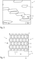
- Figure 2 shows a heat-conducting structure 2, which is composed of a large number of heat-conducting grids 20. For this purpose, around 50 to around 400 of the in Figure 1 The heat conduction grid shown is cut to size and placed on top of each other.
- the heat-conducting grids can be joined, for example, by soldering.
- a soldering paste which contains solder and flux, can be applied to the thermal conduction grid 20 in a point-like or flat manner.
- at least one thermal conduction grid can be oxidized and the contact points ground before soldering. The can prevent the heat-conducting structure from absorbing the solder due to capillary action when soldering.
- the individual heat-conducting grids 20 can be sintered by heat-treating a stack of a plurality of heat-conducting grids 20 in a protective gas atmosphere.
- the protective gas atmosphere can contain, for example, a noble gas, nitrogen or hydrogen.
- the heat-conducting structure 2 has a significantly higher mechanical stability than a single heat-conducting grid 20.
- the cross section available for heat conduction within the plane defined by the heat-conducting grids increases linearly with the number of heat-conducting grids. In the direction of the normal vector of the thermal conduction grid, however, the thermal conductivity is reduced.
- Figure 3 shows the cross section through a heat-conducting structure Figure 2 . Shown is a section of eleven heat-conducting grids 20, which are arranged one above the other. Individual webs 23 can be seen, whereas the meshes 25 are not visible in cross section.
- the individual webs 23 only touch each other at individual points.
- the heat treatment results in the formation of sintering necks 24 at these points.
- the sintering necks 24 increase the mechanical stability of the heat-conducting structure 2 the mechanical load capacity of an individual heat-conducting grid 20.
- heat conduction can also take place between individual heat-conducting grids 20 and thus along the normal vector of the heat-conducting structure 2.
- this heat conduction is approximately one order of magnitude lower than along the individual levels of the heat conduction grid 20.
- FIG 4 shows a cross section through a heat exchanger 1 according to the present invention.
- the heat exchanger 1 contains at least one tube 10, which has a tube wall 100.
- the pipe wall 100 separates an interior 105 from an external space surrounding the pipe 10.
- the cross section of the tube 10 can be polygonal or round. In some embodiments of the invention, the tube 10 may have a rectangular cross section.
- a first heat transfer medium 6 circulates in the interior 105 of the tube 10.
- the heat transfer medium 6 can be cooling or heating water or a thermal oil.
- the heat transfer medium 6 can be the working medium of a heat pump or a refrigeration machine, for example ammonia, water or a hydrocarbon.
- the first heat transfer medium 6 can condense or evaporate in the tube 10.
- the heat is supplied to or removed from the interior 105 of the pipe 10 via the pipe wall 100.
- the heat-conducting structure 2 according to the present invention is available to increase the area available for heat exchange.
- the heat-conducting structure 2 has a large number of heat-conducting grids 20. For the sake of clarity, in Figure 4 only a single heat conduction grid 20 is shown.
- the heat conduction grid 20 has elongated meshes 25, as shown in FIG Figure 1 described.
- the heat-conducting structure 2 is cohesively joined to the pipe wall 100 with a large number of joints 110. This can be done, for example, by soldering, sintering, welding or gluing. Due to the continuous material structure of the heat conduction grid 20, heat can be conducted through the cross section of the webs 23.
- the heat-conducting structure 2 is oriented such that the smaller width of the meshes 25 runs approximately parallel to the tube 10.
- a second heat transfer medium 5 can flow through the meshes 25.
- the second heat transfer medium 5 flows into the drawing plane or out of the drawing plane and thus approximately orthogonally to the flow direction of the first heat transfer medium 6.
- the flow direction of the two heat transfer media can of course also run in the same or opposite directions.
- the invention does not teach the use of a cross-flow heat exchanger as a solution principle.
- the heat-conducting structure 2 Due to the comparatively large surface area of the meshes 25 in the total area of the heat-conducting grid 20 of approximately 80% to approximately 90%, the heat-conducting structure 2 only offers a small resistance to the flow of the second heat-transfer medium 5, so that the heat-transfer medium passes through the heat-conducting structure 2 with a small pressure drop can flow.
- the second heat transfer medium 5 can be gaseous and, for example, contain or consist of ambient air.
- the height of the heat-conducting structure 2 between the joint 110 and the upper end can be between approximately 150 mm to approximately 400 mm or between approximately 200 mm to approximately 300 mm.
- FIG. 5 shows a second embodiment of a heat exchanger according to the present invention.
- the same components of the invention are provided with the same reference numbers, so that the following description is limited to the essential differences.
- the heat-conducting structure 2 is oriented such that the greater width of the mesh 25 runs approximately parallel to the tube 10.
- the joints 110 can have a larger area than in the case of Figure 4 explained first embodiment. This can improve the connection of the heat-conducting structure 2 to the wall 100 of the tubes 10.
- Figure 6 shows the heat exchangers according to Figure 4 and Figure 5 in a cutting direction orthogonal to these figures. Accordingly, the first heat transfer medium 6 flows into the drawing plane or out of the drawing plane. The flow direction of the second heat transfer medium 5 runs within the plane of the drawing.
- Figure 6 shows that the individual heat-conducting grids 20 of the heat-conducting structure 2 are located essentially vertically on the heat transfer surface 100. For reasons of clarity, the individual heat conduction grids are 20 in Figure 6 shown spaced apart. However, it is understood that the heat conducting grids 20 at least partially touch each other and are partially connected by sintering necks, as shown in FIG Figure 3 was explained.
- heat-conducting structure 2 can contain between about 50 and about 400 heat-conducting grids 20.
- Several heat-conducting structures 2 can also be arranged on a tube 10, so that a heat exchanger 1 according to the present invention can contain many thousands of heat-conducting grids 20.
- the second heat transfer medium 5 flows approximately along the normal vector of Heat-conducting structure 2. Unlike known finned heat exchangers, the heat transfer medium 5 does not flow along the individual surface elements, but through them. In other embodiments of the invention, however, the flow direction can also run in the plane of the heat transfer grids. Due to the high proportion of meshes 25 in the total area, this can still be done with a sufficiently low pressure loss. At the same time, the area available for heat transfer is increased, so that the heat exchanger according to the invention has better performance.
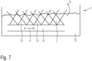
- FIG. 7 shows the use of a heat exchanger according to the invention as an evaporator.
- a heat exchanger 1 is completely or partially immersed in a sump 7 which is filled with a liquid 70 to be evaporated.
- the liquid 70 is evaporated by adding heat and leaves the sump as vapor 75.
- the evaporator can be part of a sorption heat pump.
- the heat transfer medium circulating in the pipe 10 supplies the heat necessary for evaporation.
- the heat transfer medium can be heated by a heat source (not shown) or, in the case of a refrigeration system, transport the heat to be dissipated.
- the height of the heat-conducting structure 2 between the joint on the tube 10 and the upper end can be between approximately 10 mm and approximately 100 mm or between approximately 10 mm and approximately 50 mm or approximately between 10 mm and approximately 30 mm.
- the sintered necks 24 between individual heat-conducting grids created during the heat treatment of the heat-conducting structure also form additional nucleation points for the formation of bubbles.
- the evaporation performance of a heat exchanger according to the invention can thus be significantly increased compared to known heat exchangers
Landscapes
- Physics & Mathematics (AREA)
- Engineering & Computer Science (AREA)
- Geometry (AREA)
- Thermal Sciences (AREA)
- Mechanical Engineering (AREA)
- General Engineering & Computer Science (AREA)
- Heat-Exchange Devices With Radiators And Conduit Assemblies (AREA)
Description
- Die Erfindung betrifft einen Wärmeübertrager mit zumindest einer Wärmeübertragungsfläche, welche mit zumindest einer Wärmeleitstruktur verbunden ist. Weiterhin betrifft die Erfindung ein Verfahren zum Verdampfen einer Flüssigkeit, bei welchem einer Flüssigkeit Wärme zugeführt wird. Schließlich betrifft die Erfindung ein Verfahren zum Wärmeübertrag zwischen einem ersten Wärmeträgermedium und einem zweiten Wärmeträgermedium mittels eines Wärmeübertragers. Vorrichtungen und Verfahren der eingangs genannten Art können vielfältig Verwendung finden, beispielsweise zur Entwärmung von Prozessanlagen oder Maschinen oder als Bauteil von Wärmepumpen und Klimageräten, solche Wärmeüberträger sind z.B. aus
EP 0 693 666 A2 bekannt.EP 0 693 666 A2 beschreibt den Oberbegriff des Anspruchs 1. - Aus der Praxis sind Lamellenwärmeübertrager bekannt. Diese enthalten ein Lamellenpaket, wobei einzelne Lamellen aus einem Blech aus einem Metall oder einer Legierung gefertigt sind. Das Lamellenpaket kann beispielsweise Aluminium oder Kupfer enthalten. Im Lamellenpaket sind Bohrungen angebracht, durch welche Rohrleitungen geführt sind. Ein erstes Wärmeträgermedium, beispielsweise Wasser oder ein Thermoöl, durchströmt die Rohrleitungen. Ein zweites Wärmeträgermedium, beispielsweise Umgebungsluft, durchströmt das Lamellenpaket. Dabei kann Wärme entweder vom ersten Wärmeträgermedium auf das zweite Wärmeträgermedium oder umgekehrt übertragen werden. Das Lamellenpaket ist dabei thermisch an die Rohrleitungen angebunden und führt dazu, dass die zum Wärmeaustausch zur Verfügung stehende Oberfläche vergrößert ist.
- Diese bekannten Lamellenwärmeübertrager weisen jedoch den Nachteil auf, dass die Lamellen fertigungsbedingt einen gewissen Mindestabstand zueinander aufweisen müssen und die damit zum Wärmeaustausch zur Verfügung stehende Oberfläche begrenzt ist. Dies begrenzt gleichzeitig die Leistungsfähigkeit des Wärmeübertragers, d. h. die pro Zeiteinheit übertragbare Wärmemenge.
- Ausgehend vom Stand der Technik liegt der Erfindung somit die Aufgabe zugrunde, einen Wärmeübertrager mit verbesserter Leistungsfähigkeit bereitzustellen.
- Die Aufgabe wird erfindungsgemäß durch eine Vorrichtung gemäß Anspruch 1, ein Verfahren nach Anspruch 14 und ein Verfahren nach Anspruch 15 gelöst. Vorteilhafte Weiterbildungen der Erfindung finden sich in den Unteransprüchen.
- Erfindungsgemäß wird ein Wärmeübertrager mit zumindest einerWärmeübertragungsfläche vorgeschlagen. Der Wärmeübertragungsfläche kann Wärme zu- oder abgeführt werden, beispielsweise durch elektrische Heizwiderstände, Peltier-Elemente oder Abwärmenutzung. In einigen Ausführungsformen der Erfindung kann die Wärmeübertragungsfläche eine Rohrwandung sein oder einen Teil einer Rohrwandung enthalten, welche einen Innenraum eines Rohres gegen den das Rohr umgebenden Außenraum begrenzt. In diesem Fall kann im Rohr ein Wärmeträger zirkulieren, welchem sensible und/oder latente Wärme zugeführt wird oder welchem sensible und/oder latente Wärme entnommen wird. In einigen Ausführungsformen der Erfindung kann die Wärmeübertragungsfläche Teil einer Behälterwandung sein, wobei der Behälter einen Latentwärmespeicher enthält.
- Sofern die Wärmeübertragungsfläche eine Rohrwandung ist, kann der Querschnitt des Rohres polygonal oder rund sein. Die Querschnittsfläche kann dieselbe Breite wie Höhe aufweisen, sodass der Rohrquerschnitt quadratisch oder kreisrund ist. In anderen Ausführungsformen der Erfindung kann die Breite des Rohres größer sein als dessen Höhe, sodass der Querschnitt rechteckig oder elliptisch ist. Ein Wärmetauscher, welcher eine Mehrzahl solcher Rohre aufweist, kann auch als Plattenwärmetauscher bezeichnet werden.
- Die Wärmeübertragungsfläche kann ein Metall oder eine Legierung aufweisen oder daraus bestehen. Die Wärmeübertragungsfläche kann in einigen Ausführungsformen der Erfindung Aluminium und/oder Kupfer und/oder Edelstahl enthalten oder daraus bestehen.
- Weiterhin wird vorgeschlagen, die Wärmeübertragungsfläche zumindest einseitig mit einer Wärmeleitstruktur zu versehen. Die Wärmeleitstruktur ist thermisch an die Wärmeübertragungsfläche angekoppelt, sodass die zum Wärmeaustausch zur Verfügung stehende Fläche gegenüber der reinen Wärmeübertragungsfläche vergrößert ist.
- Erfindungsgemäß wird nun vorgeschlagen, dass die Wärmeleitstruktur zumindest zwei Wärmeleitgitter enthält, welche stoffschlüssig miteinander verbunden sind. Die Wärmeleitgitter können hierzu miteinander verlötet oder verschweißt oder gesintert werden. Die Wärmeleitgitter erlauben im Gegensatz zu Lamellen aufgrund der im Gitter vorhandenen Öffnungen eine effiziente Durchströmung mit einem Wärmeträgermedium. Weiterhin weisen die Wärmeleitgitter aufgrund ihrer Öffnungen innenliegende Oberflächen auf, welche zur Vergrößerung der gesamten, zum Wärmeaustausch zur Verfügung stehenden Oberfläche beitragen. Aufgrund der stoffschlüssigen Verbindung benachbarter Wärmeleitgitter innerhalb der Wärmeleitstruktur wird der Abstand der Wärmeleitgitter gegenüber bekannten Lamellenpaketen reduziert. Hierdurch kann die Anzahl der Wärmeleitgitter vergrößert sein, wodurch die zum Wärmeaustausch zur Verfügung stehende Oberfläche ansteigt. Gleichzeitig erhöht sich durch die stoffschlüssige Verbindung benachbarter Wärmeleitgitter die mechanische Stabilität, sodass die Wärmeleitgitter eine geringere Materialstärke aufweisen können als übliche Lamellen eines Lamellenwärmeübertragers. Da innerhalb der durch ein Wärmeleitgitter definierten Ebene gleichwohl eine durchgängige Materialstruktur vorhanden ist, kann die Wärme über die Wärmeleitgitter mit großer Effizienz von der Wärmeübertragungsfläche des zumindest einen Rohres des Wärmeübertragers zu- oder abgeführt bzw. dem im Rohr strömenden Wärmeträgermedium zugeführt werden.
- In einigen Ausführungsformen der Erfindung kann zumindest ein Wärmeleitgitter ausgewählt sein aus einer perforierten Materiallage und/oder einem Streckmetallgitter und/oder einem Geflecht. Die perforierte Materiallage kann beispielsweise ein Blech bzw. eine Metallfolie aus einem Metall oder einer Legierung sein oder eine solche enthalten. Die Materiallage kann eben oder gekrümmt bzw. gewellt sein, um auf diese Weise Zwischenräume zwischen benachbarten Wärmeleitgittern der Wärmeleitstruktur zu realisieren. Ein Streckmetallgitter bzw. ein Geflecht oder ein Gestrick kann in den beiden Raumrichtungen der durch das Flächengebilde des Streckmetallgitters definierten Ebene eine anisotrope Wärmeleitfähigkeit aufweisen, sodass die Wärmeleitfähigkeit orthogonal zur Wärmeübertragungsfläche größer sein kann als in einer Richtung parallel zur Wärmeübertragungsfläche. Hierdurch kann Wärme effizient der Wärmeübertragungsfläche zu- bzw. abgeführt werden. Im Falle eines Streckmetallgitters kann dies dadurch erfolgen, dass die im Gitter ausgebildeten Maschen nicht quadratisch sind, sondern eine größere Ausdehnung in einer Raumrichtung aufweisen als in einer dazu orthogonalen Raumrichtung. Im Falle eines Geflechtes bzw. eines Gewebes kann die Anzahl bzw. Flächendichte der im Geflecht bzw. Gewebe vorhandenen Fäden in einer Raumrichtung größer sein als in einer hierzu orthogonalen Raumrichtung.
- In einigen Ausführungsformen der Erfindung können die einzelnen Wärmeleitgitter eine Materialstärke von weniger als etwa 200 µm oder weniger als etwa 150 µm oder weniger als etwa 60 µm aufweisen. In einigen Ausführungsformen der Erfindung können die einzelnen Wärmeleitgitter eine Materialstärke von mehr als etwa 20 µm oder mehr als etwa 30 µm oder mehr als etwa 90 µm aufweisen. In einigen Ausführungsformen der Erfindung können die Wärmeleitgitter eine Materialstärke von etwa 50 µm aufweisen. Die genannten Materialstärken erlauben einerseits einen hinreichenden Wärmetransport innerhalb der durch das Wärmeleitgitter definierten Ebene und andererseits eine hinreichende Packungsdichte, um hohe Leistungsdichten des erfindungsgemäßen Wärmeübertragers zu erzielen.
- In einigen Ausführungsformen der Erfindung kann die Wärmeleitstruktur so auf der Wärmeübertragungsfläche angeordnet sein, dass die Wärmeleitgitter mit dem Rohr bzw. der Längsachse des Rohres einen Winkel von etwa 50° bis etwa 130° oder von etwa 70° bis etwa 110° oder von etwa 80° bis etwa 100° oder etwa 90° einschließen. Dies erlaubt einerseits eine effiziente Durchströmung der Wärmeleitstruktur, beispielsweise in einem Querstromwärmetauscher. Andererseits ist die projizierte Fläche der Wärmeleitstruktur maximal, wenn diese etwa 90° zur Wärmeübertragungsfläche und zur Strömung des Wärmeträgermediums angeordnet ist. Hierdurch können Strömungsverluste minimiert und die Wärmeübertragungsleistung maximiert werden.
- In einigen Ausführungsformen der Erfindung kann die Wärmeleitstruktur durch Sintern der Wärmeleitgitter hergestellt werden. Zum Sintern kann ein Stapel von Wärmeleitgittern in Schutzgasatmosphäre oder Vakuum auf eine vorgebbare Temperatur erwärmt werden. In einigen Ausführungsformen der Erfindung kann diese Temperatur unterhalb der Schmelztemperatur und über der halben Schmelztemperatur des für die Wärmeleitgitter verwendeten Materials gewählt sein. Hierdurch kommt es zum Verschweißen der Wärmeleitgitter bzw. zur Ausbildung von Sinterhälsen an einzelnen Berührungspunkten. Dies kann die mechanische Stabilität auch dünner Wärmeleitgitter soweit erhöhen, dass der Wärmeübertrager mechanisch robust ausgeführt werden kann. Erfindungsgemäß wurde erkannt, dass durch das Sintern einer Mehrzahl von Wärmeleitgittern eine Wärmeleitstruktur entsteht, deren Porosität nur unwesentlich geringer ist als die offene Fläche einzelner Wärmeleitgitter. Somit kann die erfindungsgemäße Wärmeleitstruktur mit geringen Druckverlusten vom Wärmeträgermedium durchströmt werden und beim Einsatz als Verdampfer kann sich in der Wärmeleitstruktur eine großflächige Dreiphasengrenze zwischen der Wärme übertragenden Fläche der Wärmeleitstruktur, der zu verdampfenden Flüssigkeit und dem Dampf ausbilden.
- In einigen Ausführungsformen der Erfindung kann die Wärmeleitstruktur eine Höhe von etwa 1 mm bis etwa 10 mm oder etwa 1 mm bis etwa 5 mm oder etwa 1 mm bis etwa 3 mm aufweisen. Wärmeleitstrukturen, welche ausgehend von der Oberfläche der Wärmeübertragungsfläche die angegebenen Höhenmaße aufweisen, eignen sich insbesondere zur Verdampfung einer Flüssigkeit aus einem Flüssigkeitssumpf. Hierzu kann die Wärmeleitstruktur teilweise oder vollständig in den Flüssigkeitssumpf eintauchen.
- In einigen Ausführungsformen der Erfindung kann die Wärmeleitstruktur eine Höhe von etwa 15 mm bis etwa 40 mm oder von etwa 20 mm bis etwa 30 mm aufweisen. Die Höhe erstreckt sich dabei von der Oberfläche der Rohrwand ausgehend lotrecht bis zum höchsten Punkt der Wärmeleitstruktur. Solche Wärmeleitstrukturen können von einem gasförmigen Wärmeträgermedium durchströmt und dabei als Wärmeübertrager zwischen zwei Wärmeträgermedien verwendet werden und aufgrund der großen zur Verfügung stehenden Fläche auch große Leistungen übertragen.
- In einigen Ausführungsformen der Erfindung kann die Wärmeleitstruktur zwischen etwa 50 und etwa 2500 oder zwischen etwa 100 und etwa 1000 oder zwischen etwa 150 und etwa 500 oder zwischen etwa 200 und etwa 300 Wärmeleitgitter enthalten oder daraus bestehen. Die Wärmeleitgitter können nach Zuschnitt und optionaler Umformung, beispielsweise durch Strukturwalzen, übereinandergelegt und durch Sintern, Kleben oder Löten miteinander verbunden werden. Insbesondere Sintern erlaubt ein einfaches Herstellungsverfahren der erfindungsgemäßen Wärmeleitstruktur. Nach dem Sintern weist die Wärmeleitstruktur eine vergleichsweise große mechanische Stabilität und gleichzeitig eine hohe Porosität auf, welche eine effiziente Durchströmung mit einem insbesondere gasförmigen Wärmeträgermedium erlaubt. Gleichzeitig kann die Wärmeleitstruktur in den einzelnen Ebenen der Wärmeleitgitter effizient Wärme leiten, wohingegen in Richtung des Normalenvektors der Wärmeleitgitter aufgrund der nur punktartigen Verbindung der einzelnen Wärmeleitgitter untereinander eine reduzierte Wärmeleitfähigkeit gegeben ist.
- Die aus einer Vielzahl von Wärmeleitgittern zusammengesetzte Wärmeleitstruktur kann nachfolgend auf das gewünschte Maß zugeschnitten und form- oder stoffschlüssig an die Wärmeübertragungsfläche eines Wärmeübertragers gefügt werden. Hierbei kann auch eine Mehrzahl von Wärmeleitstrukturen an einer Wärmeübertragungsfläche befestigt werden.
- In einigen Ausführungsformen der Erfindung kann der Normalenvektor der Wärmeleitgitter dem Normalenvektor der Wärmeübertragungsfläche einen Winkel zwischen etwa 30° und etwa 150° oder Zwischen etwa 45° und etwa 135° oder Zwischen etwa 70° und etwa 110° oder etwa 90° einschließen. Dadurch wird die Wärme entlang der Ebenen der Wärmeleitgitter von der Wärmeübertragungsfläche abgeführt.
- Gemäss der Erfindung weist die Wärmeleitstruktur eine Porosität von etwa 70 % bis etwa 90 % oder von etwa 80 % bis etwa 85 % auf. Erfindungsgemäß wurde erkannt, dass auch beim Aufeinanderlegen einer Vielzahl von Wärmeleitgittern die offene Fläche, welche den Strömungswiderstand eines Wärmeträgermediums maßgeblich bestimmt, nur im geringen Umfang sinkt.
- In einigen Ausführungsformen der Erfindung kann die Maschengröße der einzelnen Maschen eines Wärmeleitgitters zwischen etwa 1,5 mm und etwa 3,5 mm betragen. In einigen Ausführungsformen der Erfindung kann die Breite einer Masche größer sein als deren Höhe. In einigen Ausführungsformen der Erfindung kann die Breite einer Masche zwischen etwa 2,2 mm bis etwa 3,5 mm betragen. In diesen Ausführungsformen der Erfindung kann die Höhe einer Masche zwischen etwa 1,5 mm und etwa 2,5 mm betragen. In einigen Ausführungsformen der Erfindung kann die Stegbreite des Wärmeleitgitters, d.h. die zwischen benachbarten Maschen verbleibende Materialdicke, zwischen etwa 180 µm und etwa 50 µm oder zwischen etwa 150 µm und etwa 80 µm betragen. In anderen Ausführungsformen der Erfindung kann die Stegbreite zwischen etwa 120 µm und etwa 90 µm betragen. Somit erlaubt die vergleichsweise große Maschengröße die effiziente Durchströmung mit einem Wärmeträgermedium oder im Falle eines Verdampfers die effiziente Abführung eines gasförmigen Mediums, wohingegen die verbleibende Stegbreite noch einen hinreichenden Wärmetransport innerhalb der Wärmeleitstruktur sicherstellt.
- In einigen Ausführungsformen der Erfindung kann die Wärmeleitfähigkeit der Wärmeleitstruktur in Richtung des Normalenvektors der durch die Wärmeleitgitter definierten Ebene um mehr als einen Faktor 7 oder mehr als einen Faktor 8 oder mehr als einen Faktor 10 geringer sein als in einer zum Normalenvektor orthogonalen Richtung. Dieses Verhalten ergibt sich daraus, dass innerhalb der durch die einzelnen Wärmeleitgitter definierten Ebene aufgrund der zusammenhängenden Materiallage der Wärmeleitgitter eine vergleichsweise große Querschnittsfläche zum Wärmetransport zur Verfügung steht. Andererseits sind benachbarte Wärmeleitgitter nur punktförmig durch Sinterhälse, Lötstellen oder Klebeverbindungen miteinander verbunden, sodass die Wärmeleitung in Richtung des Normalenvektors reduziert ist.
- In einigen Ausführungsformen der Erfindung kann der Wärmeübertrager weiterhin ein Sorptionsmittel enthalten, welches auf und/oder in der Wärmeleitstruktur angeordnet ist. Das Sorptionsmittel kann beispielsweise durch Plasmabeschichten, Tauchbeschichtung oder Sprühbeschichtung aufgebracht werden. Dies erlaubt es, den erfindungsgemäßen Wärmeübertrager als Sorber in einem thermischen Kompressor einer Sorptionswärmepumpe einzusetzen. In anderen Ausführungsformen der Erfindung kann der Wärmeübertrager auch als Kondensator und/oder Verdampfer einer Wärmepumpe Verwendung finden.
- In einigen Ausführungsformen der Erfindung kann die Wärmeleitstruktur plissiert sein.
- In anderen Ausführungsformen der Erfindung kann die Wärmeleitstruktur stoffschlüssig mit dem Rohr verbunden sein, beispielsweise durch Löten. Hierzu kann in einigen Ausführungsformen der Erfindung eine Lotpaste verwendet werden, welche auf die Fügestelle aufgetragen und nachfolgend erwärmt wird.
- In einigen Ausführungsformen der Erfindung betrifft dies ein Verfahren zum Verdampfen einer Flüssigkeit, bei welchem die Wärmeleitstruktur eines Wärmeübertragers zumindest teilweise in einen Sumpf eintaucht und über zumindest ein Rohr des Wärmeübertragers ein Wärmeträgermedium mit erhöhter Temperatur zugeführt wird.
- Gemäß dem vorgeschlagenen Verfahren wird über die Wärmeleitstruktur des Wärmeübertragers von einer Wärmeenergiequelle Wärme auf eine Flüssigkeit übertragen, wodurch die Flüssigkeit verdampft wird. Die Flüssigkeit kann in einigen Ausführungsformen über einen Sumpf zugeführt werden. Hierzu kann der Wärmeübertrager vollständig oder teilweise in den Sumpf eintauchen. In anderen Ausführungsformen der Erfindung kann die Flüssigkeit dem Wärmeübertrager auch durch Berieselung zugeführt werden. Schließlich kann die zu verdampfende Flüssigkeit auch vorher auf dem Wärmeübertrager kondensieren und dort zwischengespeichert werden.
- Im Falle des Eintauchens in einen Sumpf kann ein Blasensieden in der Flüssigkeit erzeugt werden. Als Blasensieden wird die Entstehung von Gasphasen durch Erwärmung innerhalb der Flüssigkeit bezeichnet.
- Bei Verdampfungsprozessen, insbesondere beim Blasensieden, treten hohe Wärmeübergangskoeffizienten innerhalb der Wärmeleitstruktur auf, welche durch die Dynamik der Blasenbildung, das Blasenwachstum sowie des Blasenabreißens bedingt sind. Für das Zustandekommen der Blasenbildung an einer Teilfläche der Wärmeleitstruktur sind dabei Blasenkeimstellen und eine gegenüber der Sättigungstemperatur des zu verdampfenden Fluides erhöhte Wandtemperaturen notwendig. Es ist bekannt, dass vor allem an Ecken und Kanten einer Heizfläche Keimstellen für die Bildung von Blasen entstehen. Der erfindungsgemäße Wärmeübertrager weist somit aufgrund der innerhalb der Wärmeleitgitter durchgehenden Materialstruktur eine gute Wärmeleitfähigkeit auf. Aufgrund der Maschen innerhalb der Wärmeleitgitter, welche jeweils durch Stege mit Kanten begrenzt sind, weist der erfindungsgemäße Wärmeübertrager aber auch viele Keimstellen zur Blasenbildung und damit eine gegenüber an sich bekannten Lamellenwärmeübertragern verbesserte Verdampfungsleistung beim Blasensieden auf. Auch die bei der Wärmebehandlung der Wärmeleitstruktur entstehenden Kontaktbereiche zwischen einzelnen Wärmeleitgittern bilden zusätzliche Keimstellen für die Bildung von Blasen. Durch die erfindungsgemäß verwendeten Wärmeleitgitter mit geringer Materialstärke lassen sich viele Wärmeleitgitter auf begrenztem Raum zusammenfügen. Die innerhalb dieser Wärmeleitgitter ausgebildeten kleinen Maschen führen zu vielen Kanten und Ecken und damit zu einer großen Anzahl von Keimstellen für die Blasenbildung. Die Verdampfungsleistung eines erfindungsgemäßen Wärmeübertragers kann somit gegenüber bekannten Wärmeübertragern deutlich erhöht sein.
- In einigen Ausführungsformen der Erfindung betrifft diese ein Verfahren zum Wärmeübertrag zwischen einem ersten Wärmeträgermedium auf ein zweites Wärmeträgermedium mittels eines Wärmeübertragers. Dabei strömt ein Wärmeträgermedium im Inneren eines Rohres und ist durch die Rohrwandung vom Außenraum getrennt, in welchem das andere Wärmeträgermedium strömt. Die zum Wärmeübergang zur Verfügung stehende Fläche kann durch Wärmeleitstrukturen vergrößert werden, welche einseitig oder beidseitig auf der Rohrwandung angeordnet sind. In einigen Ausführungsformen der Erfindung kann insbesondere die Außenseite der Rohrwandung mit Wärmeleitstrukturen versehen sein. In einigen Ausführungsformen der Erfindung kann das erste Wärmeträgermedium eine Flüssigkeit sein, beispielsweise ein Heizwasser, ein Kühlwasser oder ein Thermoöl. Das zweite Wärmeträgermedium kann in einigen Ausführungsformen der Erfindung gasförmig sein, beispielsweise Umgebungsluft oder ein Abgasstrom. In diesem Fall strömt das gasförmige zweite Wärmeträgermedium durch die erfindungsgemäße Wärmeleitstruktur. Da die Porosität, d. h. das Volumen der sich aus den Maschen ergebenden Poren im Verhältnis zum Gesamtvolumen der Wärmeleitstruktur vergleichsweise groß ist, kann auch die aus einer Vielzahl von Wärmeleitgittern bestehende Wärmeleitstruktur von einem gasförmigen Medium durchströmt werden, so dass ein effizienter Wärmeaustausch stattfinden kann.
- Nachfolgend soll die Erfindung anhand von Figuren ohne Beschränkung des allgemeinen Erfindungsgedankens näher erläutert werden. Dabei zeigt:
-
Figur 1 eine Ausführungsform eines erfindungsgemäß verwendeten Wärmeleitgitters. -
Figur 2 zeigt ein Ausführungsbeispiel einer Wärmeleitstruktur in der Ansicht. -
Figur 3 zeigt eine Wärmeleitstruktur im Querschnitt. -
Figur 4 zeigt einen Querschnitt durch einen Wärmeübertrager in einer ersten Ausführungsform. -
Figur 5 zeigt einen Querschnitt durch einen Wärmeübertrager in einer zweiten Ausführungsform. -
Figur 6 zeigt einen Querschnitt durch einen Wärmeübertrager in einer zuFig. 5 orthogonalen Richtung. -
Figur 7 zeigt die Anwendung eines erfindungsgemäßen Wärmeübertragers als Verdampfer. -
Figur 1 zeigt eine Ausführungsform eines Wärmeleitgitters gemäß der vorliegenden Erfindung. Das Wärmeleitgitter gemäßFigur 1 besteht aus einem Streckmetall, welches durch Einbringen von Schlitzen in eine Metallfolie bzw. ein -blech und nachfolgendes Auseinanderziehen erhältlich ist. Hierdurch bilden sich Maschen 25, welche durch Stege 23 voneinander getrennt sind. Die Metallfolie bzw. das -blech kann Kupfer oder Aluminium enthalten oder daraus bestehen. - In einigen Ausführungsformen der Erfindung können die Maschen 25 eine größere Breite a und eine geringere Höhe b aufweisen. In einigen Ausführungsformen der Erfindung kann die Breite a zwischen etwa 2,5 und etwa 3 mm betragen, wohingegen die Höhe b zwischen etwa 1,5 mm und etwa 2,5 mm beträgt.
- Die Stege 23 können in einigen Ausführungsformen der Erfindung zwischen etwa 90 µm und etwa 100 µm breit sein.
- Die Materialstärke des Streckmetallgitters kann in einigen Ausführungsformen der Erfindung zwischen etwa 40 µm und etwa 60 µm betragen.
- Aufgrund der Herstellungsweise des Wärmeleitgitters 20 als Streckmetallgitter ergibt sich innerhalb der durch das Streckmetallgitter 20 definierten Ebene eine durchgehende metallische Struktur, sodass Wärme innerhalb der durch das Streckmetall definierten Ebene effizient geleitet werden kann. Sofern die Maschen 25 des Wärmeleitgitters 20 von einem beispielsweise gasförmigen Wärmeträgermedium durchströmt werden, kann diese Wärme auch mit guter Effizienz an das Wärmeträgermedium abgegeben bzw. aus dem Wärmeträgermedium aufgenommen werden.
- In gleicher Weise wie vorstehend für ein Streckmeltall erläutert, kann ein Wärmeleitgitter 20 auch durch Perforieren einer Metallfolie oder durch Flechten von Drähten hergestellt werden.
-
Figur 2 zeigt eine Wärmeleitstruktur 2, welche aus einer Vielzahl von Wärmeleitgittern 20 zusammengesetzt ist. Hierzu werden etwa 50 bis etwa 400 der inFigur 1 gezeigten Wärmeleitgitter zugeschnitten und übereinandergelegt. - Das Fügen der Wärmeleitgitter kann beispielsweise durch Löten erfolgen. Hierzu kann eine Lötpaste, welche Lot und Flussmittel enthält, punktförmig oder flächig auf die Wärmeleitgitter 20 aufgebracht werden. In einigen Ausführungsformen kann zumindest ein Wärmeleitgitter vor dem Löten oxidiert und die Kontaktstellen angeschliffen werden. Das kann vermeiden, dass die Wärmeleitstruktur beim Löten durch Kapillarwirkung das Lot aufsaugt.
- In anderen Ausführungsformen der Erfindung können die einzelnen Wärmeleitgitter 20 gesintert werden, indem ein Stapel aus einer Mehrzahl von Wärmeleitgittern 20 in Schutzgasatmosphäre wärmebehandelt wird. Die Schutzgasatmosphäre kann beispielsweise ein Edelgas, Stickstoff oder Wasserstoff enthalten. Hierdurch werden die einzelnen Wärmeleitgitter 20 zur Wärmeleitstruktur 2 verbunden.
- Die Wärmeleitstruktur 2 weist eine wesentlich höhere mechanische Stabilität auf als ein einzelnes Wärmeleitgitter 20. Gleichzeitig steigt der zur Wärmeleitung zur Verfügung stehende Querschnitt innerhalb der durch die Wärmeleitgitter definierten Ebene linear mit der Anzahl der Wärmeleitgitter an. In Richtung des Normalenvektors der Wärmeleitgitter ist die Wärmeleitfähigkeit hingegen reduziert.
- Das in
Figur 2 gezeigte Halbzeug der Wärmeleitstruktur kann nachfolgend zugeschnitten und auf die Rohrwandung von zumindest einem Rohr oder einer anderen Wärmeübertragungsfläche eines Wärmeübertragers aufgebracht werden, wie anhand derFiguren 4 bis 6 noch erläutert werden wird. -
Figur 3 zeigt den Querschnitt durch eine Wärmeleitstruktur gemäßFigur 2 . Dargestellt ist ein Ausschnitt aus elf Wärmeleitgittern 20, welche übereinander angeordnet sind. Erkennbar sind einzelne Stege 23, wohingegen die Maschen 25 im Querschnitt nicht sichtbar sind. - Wie aus
Figur 3 erkennbar ist, berühren sich die einzelnen Stege 23 nur in einzelnen Punkten. Durch die Wärmebehandlung kommt es an diesen Stellen zur Ausbildung von Sinterhälsen 24. Die Sinterhälse 24 bewirken die Erhöhung der mechanischen Stabilität der Wärmeleitstruktur 2 gegenüber der mechanischen Belastbarkeit eines einzelnen Wärmeleitgitters 20. Durch die Sinterhälse 24 kann auch eine Wärmeleitung zwischen einzelnen Wärmeleitgittern 20 und damit entlang des Normalenvektors der Wärmeleitstruktur 2 erfolgen. Aufgrund des geringeren Querschnittes ist diese Wärmeleitung jedoch um etwa eine Größenordnung geringer als entlang der einzelnen Ebenen der Wärmeleitgitter 20. -
Figur 4 zeigt einen Querschnitt durch einen Wärmeübertrager 1 gemäß der vorliegenden Erfindung. Der Wärmeübertrager 1 enthält zumindest ein Rohr 10, welches eine Rohrwandung 100 aufweist. Die Rohrwandung 100 trennt einen Innenraum 105 von einem das Rohr 10 umgebenden Außenraum. Der Querschnitt des Rohres 10 kann polygonal oder rund sein. In einigen Ausführungsformen der Erfindung kann das Rohr 10 einen rechteckigen Querschnitt haben. - Bei Betrieb des Wärmeübertragers 1 zirkuliert im Innenraum 105 des Rohres 10 ein erstes Wärmeträgermedium 6. Das Wärmeträgermedium 6 kann in einigen Ausführungsformen der Erfindung Kühl- oder Heizwasser oder ein Thermoöl sein. Das Wärmeträgermedium 6 kann in anderen Ausführungsformen das Arbeitsmedium einer Wärmepumpe oder einer Kältemaschine sein, beispielsweise Ammoniak, Wasser oder ein Kohlenwasserstoff. In diesem Fall kann das erste Wärmeträgermedium 6 im Rohr 10 kondensieren oder verdampfen.
- Die Wärme wird dem Innenraum 105 des Rohres 10 über die Rohrwandung 100 zu- oder abgeführt. Zur Vergrößerung der für den Wärmeaustausch zur Verfügung stehenden Fläche steht die Wärmeleitstruktur 2 gemäß der vorliegenden Erfindung zur Verfügung. Die Wärmeleitstruktur 2 weist eine Vielzahl von Wärmeleitgittern 20 auf. Aus Gründen der Übersichtlichkeit ist in
Figur 4 lediglich ein einzelnes Wärmeleitgitter 20 dargestellt. Das Wärmeleitgitter 20 weist längliche Maschen 25 auf, wie anhand vonFigur 1 beschrieben. - Die Wärmeleitstruktur 2 ist mit einer Vielzahl von Fügestellen 110 stoffschlüssig mit der Rohrwandung 100 gefügt. Dies kann beispielsweise durch Löten, Sintern, Schweißen oder Kleben erfolgen. Aufgrund der durchgehenden Materialstruktur des Wärmeleitgitters 20 kann Wärme durch den Querschnitt der Stege 23 geleitet werden. Die Wärmeleitstruktur 2 ist so orientiert, dass die kleinere Breite der Maschen 25 in etwa parallel zum Rohr 10 verläuft.
- Die Maschen 25 können von einem zweiten Wärmeträgermedium 5 durchströmt werden. In der Zeichnung gemäß
Figur 4 strömt das zweite Wärmeträgermedium 5 in die Zeichenebene hinein bzw. aus der Zeichenebene heraus und damit in etwa orthogonal zur Strömungsrichtung des ersten Wärmeträgermediums 6. In anderen Ausführungsformen der Erfindung kann die Strömungsrichtung der beiden Wärmeträgermedien selbstverständlich auch gleich- oder gegensinnig verlaufen. Die Erfindung lehrt nicht die Verwendung eines Kreuzstromwärmeübertragers als Lösungsprinzip. Aufgrund des vergleichsweise großen Flächenanteils der Maschen 25 an der Gesamtfläche der Wärmeleitgitter 20 von ca. 80 % bis ca. 90 % setzt die Wärmeleitstruktur 2 der Strömung des zweiten Wärmeträgermediums 5 nur einen geringen Widerstand entgegen, sodass das Wärmeträgermedium mit geringem Druckabfall durch die Wärmeleitstruktur 2 strömen kann. Das zweite Wärmeträgermedium 5 kann gasfürmig sein und beispielsweise Umgebungsluft enthalten oder daraus bestehen. - Die Höhe der Wärmeleitstruktur 2 zwischen der Fügestelle 110 und dem oberen Ende kann zwischen etwa 150 mm bis etwa 400 mm oder zwischen etwa 200 mm bis etwa 300 mm aufweisen.
-
Figur 5 zeigt eine zweite Ausführungsform eines Wärmetauschers gemäß der vorliegenden Erfindung. Gleiche Bestandteile der Erfindung sind mit gleichen Bezugszeichen versehen, sodass sich die nachfolgende Beschreibung auf die wesentlichen Unterschiede beschränkt. - Wie aus
Figur 5 ersichtlich ist, ist die Wärmeleitstruktur 2 so orientiert, dass die größere Breite der Maschen 25 in etwa parallel zum Rohr 10 verläuft. Hierdurch können die Fügestellen 110 eine größere Fläche aufweisen als bei der anhand vonFigur 4 erläuterten ersten Ausführungsform. Dies kann die Anbindung der Wärmeleitstruktur 2 an die Wandung 100 der Rohre 10 verbessern. -
Figur 6 zeigt die Wärmetauscher gemäßFigur 4 undFigur 5 in einer zu diesen Figuren orthogonalen Schnittrichtung. Dementsprechend strömt das erste Wärmeträgermedium 6 in die Zeichenebene hinein bzw. aus der Zeichenebene hinaus. Die Strömungsrichtung des zweiten Wärmeträgermediums 5 verläuft innerhalb der Zeichenebene. - Auch in
Figur 6 sind gleiche Bestandteile der Erfindung mit gleichen Bezugszeichen versehen, sodass sich die Beschreibung auf die wesentlichen Unterschiede beschränken kann.Figur 6 zeigt, dass sich die einzelnen Wärmeleitgitter 20 der Wärmeleitstruktur 2 im Wesentlichen senkrecht auf der Wärmeübertragungsfläche 100 befinden. Aus Gründen der Übersichtlichkeit sind die einzelnen Wärmeleitgitter 20 inFigur 6 beabstandet dargestellt. Es versteht sich jedoch, dass sich die Wärmeleitgitter 20 zumindest teilweise berühren und teilweise durch Sinterhälse verbunden sind, wie anhand vonFigur 3 erläutert wurde. - Aus Gründen der Übersichtlichkeit sind auch lediglich sechs Wärmeleitgitter 20 in
Figur 6 dargestellt. Tatsächlich kann eine Wärmeleitstruktur 2 zwischen etwa 50 und etwa 400 Wärmeleitgittern 20 enthalten. Auf einem Rohr 10 können zudem mehrere Wärmeleitstrukturen 2 angeordnet sein, sodass ein Wärmetauscher 1 gemäß der vorliegenden Erfindung viele tausend Wärmeleitgitter 20 enthalten kann. - Wie
Figur 6 nochmals illustriert, strömt das zweite Wärmeträgermedium 5 in etwa entlang des Normalenvektors der Wärmeleitstruktur 2. Anders als bei bekannten Lamellenwärmetauschern strömt das Wärmeträgermedium 5 somit nicht an den einzelnen Flächenelementen entlang, sondern durch diese hindurch. In anderen Ausführungsformen der Erfindung kann die Strömungsrichtung jedoch auch in der Ebene der Wärmeübertragungsgitter verlaufen. Durch den hohen Anteil an Maschen 25 an der Gesamtfläche kann dies gleichwohl mit hinreichend geringem Druckverlust erfolgen. Gleichzeitig ist die zum Wärmeübertrag zur Verfügung stehende Fläche erhöht, so dass der erfindungsgemäße Wärmeübertrager eine bessere Leistungsfähigkeit aufweist. -
Figur 7 zeigt die Anwendung eines erfindungsgemäßen Wärmeübertragers als Verdampfer. Hierzu taucht ein Wärmeübertrager 1 vollständig oder teilweise in einen Sumpf 7 ein, welcher mit einer zu verdampfenden Flüssigkeit 70 gefüllt ist. Durch Wärmezufuhr wird die Flüssigkeit 70 verdampft und verlässt den Sumpf als Dampf 75. Der Verdampfer kann Bestandteil einer Sorptionswärmepumpe sein. - Auch in
Figur 7 sind gleiche Bestandteile der Erfindung mit gleichen Bezugszeichen versehen, sodass sich die Beschreibung auf die wesentlichen Unterschiede beschränkt. - Das im Rohr 10 zirkulierende Wärmeträgermedium führt die zur Verdampfung notwendige Wärme zu. Hierzu kann das Wärmeträgermedium von einer nicht dargestellten Wärmequelle erwärmt werden oder aber im Fall einer Kälteanlage die abzuführende Wärme transportieren.
- Die Verdampfungswärme wird anschließend durch die Rohrwandung der Wärmeleitstruktur 2 zugeführt. Die Höhe der Wärmeleitstruktur 2 zwischen der Fügestelle am Rohr 10 und dem oberen Ende kann in einigen Ausführungsformen der Erfindung zwischen etwa 10 mm und etwa 100 mm oder zwischen etwa 10 mm und etwa 50 mm oder etwa zwischen 10 mm und etwa 30 mm betragen.
- Beim Blasensieden der Flüssigkeit 70 treten hohe Wärmeübergangskoeffizienten innerhalb der Wärmeleitstruktur 2 auf, welche durch die Dynamik der Blasenbildung, das Blasenwachstum sowie das Blasenabreißen bedingt sind. Für das Zustandekommen der Blasenbildung an einer Teilfläche der Wärmeleitstruktur sind dabei Blasenkeimstellen und eine gegenüber der Sättigungstemperatur des zu verdampfenden Fluides erhöhte Wandtemperaturen notwendig. Da vor allem an Ecken und Kanten einer Heizfläche Keimstellen für die Bildung von Blasen entstehen, weist die erfindungsgemäße Wärmeleitstruktur 2 eine verbesserte Verdampfungsleistung auf, da an den Kanten der Stege 23 eine Vielzahl von Keimstellen vorhanden sind. Entstehender Dampf kann die Wärmeleitstruktur 2 anschließend durch die Maschen 25 verlassen. Auch die bei der Wärmebehandlung der Wärmeleitstruktur entstehenden Sinterhälse 24 zwischen einzelnen Wärmeleitgittern bilden zusätzliche Keimstellen für die Bildung von Blasen. Die Verdampfungsleistung eines erfindungsgemäßen Wärmeübertragers kann somit gegenüber bekannten Wärmeübertragern deutlich erhöht
- Selbstverständlich ist die Erfindung nicht auf die dargestellten Ausführungsformen beschränkt. Die vorstehende Beschreibung ist daher nicht als beschränkend, sondern als erläuternd anzusehen. Die nachfolgenden Ansprüche sind so zu verstehen, dass ein genanntes Merkmal in zumindest einer Aus-führungsform der Erfindung vorhanden ist. Dies schließt die Anwesenheit weiterer Merkmale nicht aus. Sofern die Ansprüche und die vorstehende Beschreibung "erste" und "zweite" Aus-führungsformen definieren, so dient diese Bezeichnung der Unterscheidung zweier gleichartiger Ausführungsformen, ohne eine Rangfolge festzulegen.
Claims (15)
- Wärmeübertrager (1) mit zumindest einer Wärmeübertragungsfläche (100), welche mit einer Wärmeleitstruktur (2) verbunden ist, wobei die Wärmeleitstruktur (2) zumindest zwei Wärmeleitgitter (20) enthält, welche stoffschlüssig miteinander verbunden sind,
dadurch gekennzeichnet, dass die Wärmeleitstruktur (2) eine Porosität von etwa 70 % bis etwa 90 % aufweist. - Wärmeübertrager nach Anspruch 1, dadurch gekennzeichnet, dass die Wärmeleitgitter (20) ausgewählt sind aus einer perforierten Materiallage und/oder einem Streckmetallgitter und/oder einem Geflecht und/oder einem Gestrick.
- Wärmeübertrager nach Anspruch 1 oder 2, dadurch gekennzeichnet, dass die einzelnen Wärmeleitgitter (20) eine Materialstärke von weniger als etwa 200 µm oder weniger als etwa 150 µm oder weniger als etwa 60 µm aufweisen.
- Wärmeübertrager nach einem der Ansprüche 1 bis 3, dadurch gekennzeichnet, dass die Wärmeleitstruktur (2) so auf der Wärmeübertragungsfläche (100) angeordnet ist, dass die Wärmeleitgitter (20) mit dem Normalenvektor der Wärmeübertragungsfläche einen Winkel (β) von etwa 30° bis etwa 150° oder von etwa 70° bis etwa 110° oder von etwa 80° bis etwa 100° oder etwa 90° einschließen.
- Wärmeübertrager nach einem der Ansprüche 1 bis 4, dadurch gekennzeichnet, dass die Wärmeübertragungsfläche (100) eine Rohrwandung eines Rohres (10) ist oder eine solche enthält.
- Wärmeübertrager nach einem der Ansprüche 1 bis 5, dadurch gekennzeichnet, dass die Wärmeleitstruktur (2) durch Sintern der Wärmeleitgitter (20) hergestellt ist.
- Wärmeübertrager nach einem der Ansprüche 1 bis 6, dadurch gekennzeichnet, dass die Wärmeleitstruktur (2) eine Höhe von etwa 1 mm bis etwa 10 mm oder etwa 1 mm bis etwa 5 mm oder etwa 1 mm bis etwa 3 mm oder etwa 15 mm bis etwa 40 mm oder etwa 20 mm bis etwa 30 mm aufweist.
- Wärmeübertrager nach einem der Ansprüche 1 bis 7, dadurch gekennzeichnet, dass die Wärmeleitstruktur (2) zwischen etwa 50 und etwa 2500 oder zwischen etwa 100 und etwa 1000 oder zwischen etwa 150 und etwa 500 oder zwischen etwa 200 und etwa 300 Wärmeleitgitter (20) enthält oder daraus besteht.
- Wärmeübertrager nach einem der Ansprüche 1 bis 8, dadurch gekennzeichnet, dass die Wärmeleitstruktur (2) eine Porosität von etwa 80% bis etwa 85% aufweist.
- Wärmeübertrager nach einem der Ansprüche 1 bis 9, dadurch gekennzeichnet, dass die Maschengröße (a, b) des Wärmeleitgitters (20) zwischen etwa 1,5 mm und etwa 3,5 mm beträgt und/oder
dass die Breite eine Steges (23) des Wärmeleitgitters (20) zwischen etwa 180 µm und etwa 50 µm beträgt. - Wärmeübertrager nach einem der Ansprüche 1 bis 10,
dadurch gekennzeichnet, dass die Wärmeleitfähigkeit der Wärmeleitstruktur (2) in Richtung des Normalenvektors der durch die Wärmeleitgitter (20) definierten Ebene um mehr als einen Faktor 7 oder mehr als einen Faktor 8 oder mehr als einen Faktor 10 geringer ist als ein einer zum Normalenvektor ortogonalen Richtung. - Wärmeübertrager nach einem der Ansprüche 1 bis 11, weiterhin enthaltend ein Sorptionsmittel, welches auf und/oder in der Wärmeleitstruktur (2) angeordnet ist.
- Wärmeübertrager nach einem der Ansprüche 1 bis 12, dadurch gekennzeichnet, dass die Wärmeleitstruktur (2) plissiert ist und/oder dass die Wärmeleitstruktur (2) stoffschlüssig mit dem Rohr (10) verbunden ist.
- Verfahren zum Verdampfen einer Flüssigkeit, dadurch gekennzeichnet, dass eine Wärmeleitstruktur (2) eines Wärmeübertragers (1) nach einem der Ansprüche 1 bis 13 zumindest teilweise in einen Sumpf eintaucht und zumindest ein Rohr (10) des Wärmeübertrager (1) von einem ersten Wärmeträgermedium (6) durchströmt wird.
- Verfahren zum Wärmeübertrag zwischen einem ersten Wärmeträgermedium (6) auf ein zweites Wärmeträgermedium (5) mittels eines Wärmeübertragers (1), dadurch gekennzeichnet, dass eine Wärmeleitstruktur (2) eines Wärmeübertragers (1) nach einem der Ansprüche 1 bis 13 vom zweiten Wärmeträgermedium (5) durchströmt wird und zumindest ein Rohr (10) des Wärmeübertragers (1) vom ersten Wärmeträgermedium (6) durchströmt wird.
Applications Claiming Priority (2)
| Application Number | Priority Date | Filing Date | Title |
|---|---|---|---|
| DE102016224338.1A DE102016224338A1 (de) | 2016-12-07 | 2016-12-07 | Wärmeübertrager und Verfahren zu dessen Verwendung |
| PCT/EP2017/081648 WO2018104375A1 (de) | 2016-12-07 | 2017-12-06 | Wärmeübertrager und verfahren zu dessen verwendung |
Publications (2)
| Publication Number | Publication Date |
|---|---|
| EP3551957A1 EP3551957A1 (de) | 2019-10-16 |
| EP3551957B1 true EP3551957B1 (de) | 2024-02-14 |
Family
ID=60654957
Family Applications (1)
| Application Number | Title | Priority Date | Filing Date |
|---|---|---|---|
| EP17811925.1A Active EP3551957B1 (de) | 2016-12-07 | 2017-12-06 | Wärmeübertrager und verfahren zu dessen verwendung |
Country Status (3)
| Country | Link |
|---|---|
| EP (1) | EP3551957B1 (de) |
| DE (1) | DE102016224338A1 (de) |
| WO (1) | WO2018104375A1 (de) |
Family Cites Families (12)
| Publication number | Priority date | Publication date | Assignee | Title |
|---|---|---|---|---|
| DE1451009A1 (de) * | 1963-07-10 | 1969-03-13 | Siemens Elektrogeraete Gmbh | Waermeaustauscher |
| FR2085171B1 (de) * | 1969-12-23 | 1974-02-01 | Radial Ste Nle | |
| DE2714617C2 (de) * | 1977-04-01 | 1982-08-26 | Spiro Research B.V., Helmond | Wärmeaustauscher mit auf einem Trägerrohr angeordneter Drahtwendel |
| US5305824A (en) * | 1993-09-27 | 1994-04-26 | Gasseling John B | Oil filter cooler |
| ES2149030T3 (es) * | 1994-07-22 | 2000-10-16 | Mitsubishi Electric Corp | Intercambiador de calor. |
| DE29721686U1 (de) * | 1996-11-27 | 1998-01-22 | Joh. Vaillant Gmbh U. Co, 42859 Remscheid | Wärmetauscher |
| DE19961284A1 (de) * | 1999-12-18 | 2001-07-12 | Bosch Gmbh Robert | Wärmeübertrager für Gasheizgeräte, insbesondere Brennwertgeräte |
| EP2211126A1 (de) * | 2005-12-19 | 2010-07-28 | Behr GmbH & Co. KG | Sorptionswärmeübertragerwand und Sorptionswärmeübertrager |
| RU2311600C1 (ru) * | 2006-06-20 | 2007-11-27 | Владимир Сергеевич Попов | Трубчатый теплообменник (варианты) |
| DE102009018197A1 (de) * | 2008-04-24 | 2009-11-26 | Scheller, Gudrun Charlotte | Flächengebilde |
| FR2993967B1 (fr) * | 2012-07-24 | 2014-08-29 | Valeo Systemes Thermiques | Ailette destinee a perturber l'ecoulement d'un fluide, echangeur de chaleur comprenant une telle ailette et procede de fabrication d'une telle ailette |
| DE102014223250A1 (de) * | 2014-11-14 | 2016-05-19 | Vaillant Gmbh | Verdampfer-Wärmetauscher |
-
2016
- 2016-12-07 DE DE102016224338.1A patent/DE102016224338A1/de not_active Ceased
-
2017
- 2017-12-06 WO PCT/EP2017/081648 patent/WO2018104375A1/de not_active Ceased
- 2017-12-06 EP EP17811925.1A patent/EP3551957B1/de active Active
Also Published As
| Publication number | Publication date |
|---|---|
| DE102016224338A1 (de) | 2018-06-07 |
| EP3551957A1 (de) | 2019-10-16 |
| WO2018104375A1 (de) | 2018-06-14 |
Similar Documents
| Publication | Publication Date | Title |
|---|---|---|
| EP1987300B1 (de) | Adsorptions-wärmepumpe, adsorptions-kältemaschine und adsorberelemente hierfür | |
| EP2414746B1 (de) | Arbeitsmittelspeicher, wärmeübertrager und wärmepumpe | |
| EP1918668A1 (de) | Vorrichtung zur Aufnahme eines Fluids mittels Kapillarkräften und Verfahren zur Herstellung der Vorrichtung | |
| EP2377596B1 (de) | Kältetrockner, insbesondere druckluftkältetrockner, sowie wärmetauscher für einen kältetrockner, insbesondere druckluftkältetrockner | |
| WO2015028125A1 (de) | Verfahren zur herstellung eines plattenwärmetauschers mit mehreren durch lotbeschichtete träger verbundenen wärmetauscherblöcken | |
| DE112017000913B4 (de) | Kühlelement und Energiespeichermodul | |
| DE112014004473T5 (de) | Kältespeicher-Wärmetauscher | |
| DE10158387B4 (de) | Anordnung zur Kühlung von elektrischen Komponenten | |
| WO2015014772A1 (de) | Adsorptionsmodul | |
| EP2418450B1 (de) | Wärmeübertrager aus einer dreidimensionalen textilen Struktur, Verfahren zu dessen Herstellung und dessen Verwendung | |
| DE202018103701U1 (de) | Metallische Kühlvorrichtung | |
| EP0106262B1 (de) | Wärmetauscher, insbesondere Heizkörper | |
| EP3551957B1 (de) | Wärmeübertrager und verfahren zu dessen verwendung | |
| DE102019001810A1 (de) | Adsorptiver Wärme- und Stoffübertrager | |
| DE3011011A1 (de) | Plattenwaermetauscher | |
| WO2018091567A1 (de) | Wärmetauscherstruktur und verfahren zu deren herstellung und verwendung | |
| WO2018041416A1 (de) | Verfahren zur herstellung eines plattenwärmeübertragerblocks mit gezielter applikation des lotmaterials auf insbesondere fins und sidebars | |
| DE112018002936T5 (de) | Gestapelter Wärmetauscher und Verfahren zum Herstellen eines gestapelten Wärmetauschers | |
| WO2010000255A1 (de) | Kompakter lamellenwärmetauscher | |
| DE102016222697B3 (de) | Wärmetauscher und Verfahren zu dessen Herstellung | |
| DE102019134587B4 (de) | Wärmeübertrager und Adsorptionsmaschine | |
| DE2406432A1 (de) | Kuehleinrichtung mit chemischem verdampfungs-kuehlmittel | |
| DE202023001602U1 (de) | Lamellen-Wärmeübertrager | |
| AT202425B (de) | Verfahren zur Herstellung eines Rohrkühlers aus Aluminium oder Aluminiumlegierungen | |
| DE102009015102A1 (de) | Arbeitsmittelspeicher, Wärmeübertrager und Wärmepumpe |
Legal Events
| Date | Code | Title | Description |
|---|---|---|---|
| STAA | Information on the status of an ep patent application or granted ep patent |
Free format text: STATUS: UNKNOWN |
|
| STAA | Information on the status of an ep patent application or granted ep patent |
Free format text: STATUS: THE INTERNATIONAL PUBLICATION HAS BEEN MADE |
|
| PUAI | Public reference made under article 153(3) epc to a published international application that has entered the european phase |
Free format text: ORIGINAL CODE: 0009012 |
|
| STAA | Information on the status of an ep patent application or granted ep patent |
Free format text: STATUS: REQUEST FOR EXAMINATION WAS MADE |
|
| 17P | Request for examination filed |
Effective date: 20190705 |
|
| AK | Designated contracting states |
Kind code of ref document: A1 Designated state(s): AL AT BE BG CH CY CZ DE DK EE ES FI FR GB GR HR HU IE IS IT LI LT LU LV MC MK MT NL NO PL PT RO RS SE SI SK SM TR |
|
| AX | Request for extension of the european patent |
Extension state: BA ME |
|
| RIN1 | Information on inventor provided before grant (corrected) |
Inventor name: SCHNABEL, LENA Inventor name: FINK, MARCEL Inventor name: ANDERSEN, OLAF Inventor name: ROHNE, MARCUS |
|
| DAV | Request for validation of the european patent (deleted) | ||
| DAX | Request for extension of the european patent (deleted) | ||
| STAA | Information on the status of an ep patent application or granted ep patent |
Free format text: STATUS: EXAMINATION IS IN PROGRESS |
|
| 17Q | First examination report despatched |
Effective date: 20200910 |
|
| RAP3 | Party data changed (applicant data changed or rights of an application transferred) |
Owner name: FRAUNHOFER-GESELLSCHAFT ZUR FOERDERUNG DER ANGEWANDTEN FORSCHUNG E.V. |
|
| GRAP | Despatch of communication of intention to grant a patent |
Free format text: ORIGINAL CODE: EPIDOSNIGR1 |
|
| STAA | Information on the status of an ep patent application or granted ep patent |
Free format text: STATUS: GRANT OF PATENT IS INTENDED |
|
| INTG | Intention to grant announced |
Effective date: 20231005 |
|
| GRAS | Grant fee paid |
Free format text: ORIGINAL CODE: EPIDOSNIGR3 |
|
| GRAA | (expected) grant |
Free format text: ORIGINAL CODE: 0009210 |
|
| STAA | Information on the status of an ep patent application or granted ep patent |
Free format text: STATUS: THE PATENT HAS BEEN GRANTED |
|
| AK | Designated contracting states |
Kind code of ref document: B1 Designated state(s): AL AT BE BG CH CY CZ DE DK EE ES FI FR GB GR HR HU IE IS IT LI LT LU LV MC MK MT NL NO PL PT RO RS SE SI SK SM TR |
|
| REG | Reference to a national code |
Ref country code: GB Ref legal event code: FG4D Free format text: NOT ENGLISH |
|
| REG | Reference to a national code |
Ref country code: CH Ref legal event code: EP |
|
| REG | Reference to a national code |
Ref country code: DE Ref legal event code: R096 Ref document number: 502017015836 Country of ref document: DE |
|
| REG | Reference to a national code |
Ref country code: IE Ref legal event code: FG4D Free format text: LANGUAGE OF EP DOCUMENT: GERMAN |
|
| REG | Reference to a national code |
Ref country code: LT Ref legal event code: MG9D |
|
| REG | Reference to a national code |
Ref country code: NL Ref legal event code: MP Effective date: 20240214 |
|
| PG25 | Lapsed in a contracting state [announced via postgrant information from national office to epo] |
Ref country code: IS Free format text: LAPSE BECAUSE OF FAILURE TO SUBMIT A TRANSLATION OF THE DESCRIPTION OR TO PAY THE FEE WITHIN THE PRESCRIBED TIME-LIMIT Effective date: 20240614 |
|
| PG25 | Lapsed in a contracting state [announced via postgrant information from national office to epo] |
Ref country code: LT Free format text: LAPSE BECAUSE OF FAILURE TO SUBMIT A TRANSLATION OF THE DESCRIPTION OR TO PAY THE FEE WITHIN THE PRESCRIBED TIME-LIMIT Effective date: 20240214 |
|
| PG25 | Lapsed in a contracting state [announced via postgrant information from national office to epo] |
Ref country code: GR Free format text: LAPSE BECAUSE OF FAILURE TO SUBMIT A TRANSLATION OF THE DESCRIPTION OR TO PAY THE FEE WITHIN THE PRESCRIBED TIME-LIMIT Effective date: 20240515 |
|
| PG25 | Lapsed in a contracting state [announced via postgrant information from national office to epo] |
Ref country code: HR Free format text: LAPSE BECAUSE OF FAILURE TO SUBMIT A TRANSLATION OF THE DESCRIPTION OR TO PAY THE FEE WITHIN THE PRESCRIBED TIME-LIMIT Effective date: 20240214 Ref country code: NL Free format text: LAPSE BECAUSE OF FAILURE TO SUBMIT A TRANSLATION OF THE DESCRIPTION OR TO PAY THE FEE WITHIN THE PRESCRIBED TIME-LIMIT Effective date: 20240214 Ref country code: RS Free format text: LAPSE BECAUSE OF FAILURE TO SUBMIT A TRANSLATION OF THE DESCRIPTION OR TO PAY THE FEE WITHIN THE PRESCRIBED TIME-LIMIT Effective date: 20240514 |
|
| PG25 | Lapsed in a contracting state [announced via postgrant information from national office to epo] |
Ref country code: ES Free format text: LAPSE BECAUSE OF FAILURE TO SUBMIT A TRANSLATION OF THE DESCRIPTION OR TO PAY THE FEE WITHIN THE PRESCRIBED TIME-LIMIT Effective date: 20240214 |
|
| PG25 | Lapsed in a contracting state [announced via postgrant information from national office to epo] |
Ref country code: RS Free format text: LAPSE BECAUSE OF FAILURE TO SUBMIT A TRANSLATION OF THE DESCRIPTION OR TO PAY THE FEE WITHIN THE PRESCRIBED TIME-LIMIT Effective date: 20240514 Ref country code: NO Free format text: LAPSE BECAUSE OF FAILURE TO SUBMIT A TRANSLATION OF THE DESCRIPTION OR TO PAY THE FEE WITHIN THE PRESCRIBED TIME-LIMIT Effective date: 20240514 Ref country code: NL Free format text: LAPSE BECAUSE OF FAILURE TO SUBMIT A TRANSLATION OF THE DESCRIPTION OR TO PAY THE FEE WITHIN THE PRESCRIBED TIME-LIMIT Effective date: 20240214 Ref country code: LT Free format text: LAPSE BECAUSE OF FAILURE TO SUBMIT A TRANSLATION OF THE DESCRIPTION OR TO PAY THE FEE WITHIN THE PRESCRIBED TIME-LIMIT Effective date: 20240214 Ref country code: IS Free format text: LAPSE BECAUSE OF FAILURE TO SUBMIT A TRANSLATION OF THE DESCRIPTION OR TO PAY THE FEE WITHIN THE PRESCRIBED TIME-LIMIT Effective date: 20240614 Ref country code: HR Free format text: LAPSE BECAUSE OF FAILURE TO SUBMIT A TRANSLATION OF THE DESCRIPTION OR TO PAY THE FEE WITHIN THE PRESCRIBED TIME-LIMIT Effective date: 20240214 Ref country code: GR Free format text: LAPSE BECAUSE OF FAILURE TO SUBMIT A TRANSLATION OF THE DESCRIPTION OR TO PAY THE FEE WITHIN THE PRESCRIBED TIME-LIMIT Effective date: 20240515 Ref country code: FI Free format text: LAPSE BECAUSE OF FAILURE TO SUBMIT A TRANSLATION OF THE DESCRIPTION OR TO PAY THE FEE WITHIN THE PRESCRIBED TIME-LIMIT Effective date: 20240214 Ref country code: ES Free format text: LAPSE BECAUSE OF FAILURE TO SUBMIT A TRANSLATION OF THE DESCRIPTION OR TO PAY THE FEE WITHIN THE PRESCRIBED TIME-LIMIT Effective date: 20240214 Ref country code: BG Free format text: LAPSE BECAUSE OF FAILURE TO SUBMIT A TRANSLATION OF THE DESCRIPTION OR TO PAY THE FEE WITHIN THE PRESCRIBED TIME-LIMIT Effective date: 20240214 |
|
| PG25 | Lapsed in a contracting state [announced via postgrant information from national office to epo] |
Ref country code: PT Free format text: LAPSE BECAUSE OF FAILURE TO SUBMIT A TRANSLATION OF THE DESCRIPTION OR TO PAY THE FEE WITHIN THE PRESCRIBED TIME-LIMIT Effective date: 20240614 Ref country code: PL Free format text: LAPSE BECAUSE OF FAILURE TO SUBMIT A TRANSLATION OF THE DESCRIPTION OR TO PAY THE FEE WITHIN THE PRESCRIBED TIME-LIMIT Effective date: 20240214 |
|
| PG25 | Lapsed in a contracting state [announced via postgrant information from national office to epo] |
Ref country code: SE Free format text: LAPSE BECAUSE OF FAILURE TO SUBMIT A TRANSLATION OF THE DESCRIPTION OR TO PAY THE FEE WITHIN THE PRESCRIBED TIME-LIMIT Effective date: 20240214 Ref country code: PT Free format text: LAPSE BECAUSE OF FAILURE TO SUBMIT A TRANSLATION OF THE DESCRIPTION OR TO PAY THE FEE WITHIN THE PRESCRIBED TIME-LIMIT Effective date: 20240614 Ref country code: PL Free format text: LAPSE BECAUSE OF FAILURE TO SUBMIT A TRANSLATION OF THE DESCRIPTION OR TO PAY THE FEE WITHIN THE PRESCRIBED TIME-LIMIT Effective date: 20240214 Ref country code: LV Free format text: LAPSE BECAUSE OF FAILURE TO SUBMIT A TRANSLATION OF THE DESCRIPTION OR TO PAY THE FEE WITHIN THE PRESCRIBED TIME-LIMIT Effective date: 20240214 |
|
| PG25 | Lapsed in a contracting state [announced via postgrant information from national office to epo] |
Ref country code: DK Free format text: LAPSE BECAUSE OF FAILURE TO SUBMIT A TRANSLATION OF THE DESCRIPTION OR TO PAY THE FEE WITHIN THE PRESCRIBED TIME-LIMIT Effective date: 20240214 |
|
| PG25 | Lapsed in a contracting state [announced via postgrant information from national office to epo] |
Ref country code: SM Free format text: LAPSE BECAUSE OF FAILURE TO SUBMIT A TRANSLATION OF THE DESCRIPTION OR TO PAY THE FEE WITHIN THE PRESCRIBED TIME-LIMIT Effective date: 20240214 |
|
| PG25 | Lapsed in a contracting state [announced via postgrant information from national office to epo] |
Ref country code: EE Free format text: LAPSE BECAUSE OF FAILURE TO SUBMIT A TRANSLATION OF THE DESCRIPTION OR TO PAY THE FEE WITHIN THE PRESCRIBED TIME-LIMIT Effective date: 20240214 Ref country code: CZ Free format text: LAPSE BECAUSE OF FAILURE TO SUBMIT A TRANSLATION OF THE DESCRIPTION OR TO PAY THE FEE WITHIN THE PRESCRIBED TIME-LIMIT Effective date: 20240214 |
|
| PG25 | Lapsed in a contracting state [announced via postgrant information from national office to epo] |
Ref country code: SK Free format text: LAPSE BECAUSE OF FAILURE TO SUBMIT A TRANSLATION OF THE DESCRIPTION OR TO PAY THE FEE WITHIN THE PRESCRIBED TIME-LIMIT Effective date: 20240214 |
|
| PG25 | Lapsed in a contracting state [announced via postgrant information from national office to epo] |
Ref country code: SM Free format text: LAPSE BECAUSE OF FAILURE TO SUBMIT A TRANSLATION OF THE DESCRIPTION OR TO PAY THE FEE WITHIN THE PRESCRIBED TIME-LIMIT Effective date: 20240214 Ref country code: SK Free format text: LAPSE BECAUSE OF FAILURE TO SUBMIT A TRANSLATION OF THE DESCRIPTION OR TO PAY THE FEE WITHIN THE PRESCRIBED TIME-LIMIT Effective date: 20240214 Ref country code: RO Free format text: LAPSE BECAUSE OF FAILURE TO SUBMIT A TRANSLATION OF THE DESCRIPTION OR TO PAY THE FEE WITHIN THE PRESCRIBED TIME-LIMIT Effective date: 20240214 Ref country code: EE Free format text: LAPSE BECAUSE OF FAILURE TO SUBMIT A TRANSLATION OF THE DESCRIPTION OR TO PAY THE FEE WITHIN THE PRESCRIBED TIME-LIMIT Effective date: 20240214 Ref country code: DK Free format text: LAPSE BECAUSE OF FAILURE TO SUBMIT A TRANSLATION OF THE DESCRIPTION OR TO PAY THE FEE WITHIN THE PRESCRIBED TIME-LIMIT Effective date: 20240214 Ref country code: CZ Free format text: LAPSE BECAUSE OF FAILURE TO SUBMIT A TRANSLATION OF THE DESCRIPTION OR TO PAY THE FEE WITHIN THE PRESCRIBED TIME-LIMIT Effective date: 20240214 |
|
| REG | Reference to a national code |
Ref country code: DE Ref legal event code: R097 Ref document number: 502017015836 Country of ref document: DE |
|
| PG25 | Lapsed in a contracting state [announced via postgrant information from national office to epo] |
Ref country code: IT Free format text: LAPSE BECAUSE OF FAILURE TO SUBMIT A TRANSLATION OF THE DESCRIPTION OR TO PAY THE FEE WITHIN THE PRESCRIBED TIME-LIMIT Effective date: 20240214 |
|
| PLBE | No opposition filed within time limit |
Free format text: ORIGINAL CODE: 0009261 |
|
| STAA | Information on the status of an ep patent application or granted ep patent |
Free format text: STATUS: NO OPPOSITION FILED WITHIN TIME LIMIT |
|
| PG25 | Lapsed in a contracting state [announced via postgrant information from national office to epo] |
Ref country code: IT Free format text: LAPSE BECAUSE OF FAILURE TO SUBMIT A TRANSLATION OF THE DESCRIPTION OR TO PAY THE FEE WITHIN THE PRESCRIBED TIME-LIMIT Effective date: 20240214 |
|
| PGFP | Annual fee paid to national office [announced via postgrant information from national office to epo] |
Ref country code: DE Payment date: 20241216 Year of fee payment: 8 |
|
| 26N | No opposition filed |
Effective date: 20241115 |
|
| PG25 | Lapsed in a contracting state [announced via postgrant information from national office to epo] |
Ref country code: SI Free format text: LAPSE BECAUSE OF FAILURE TO SUBMIT A TRANSLATION OF THE DESCRIPTION OR TO PAY THE FEE WITHIN THE PRESCRIBED TIME-LIMIT Effective date: 20240214 |
|
| PG25 | Lapsed in a contracting state [announced via postgrant information from national office to epo] |
Ref country code: MC Free format text: LAPSE BECAUSE OF FAILURE TO SUBMIT A TRANSLATION OF THE DESCRIPTION OR TO PAY THE FEE WITHIN THE PRESCRIBED TIME-LIMIT Effective date: 20240214 |
|
| REG | Reference to a national code |
Ref country code: CH Ref legal event code: PL |
|
| PG25 | Lapsed in a contracting state [announced via postgrant information from national office to epo] |
Ref country code: LU Free format text: LAPSE BECAUSE OF NON-PAYMENT OF DUE FEES Effective date: 20241206 |
|
| GBPC | Gb: european patent ceased through non-payment of renewal fee |
Effective date: 20241206 |
|
| REG | Reference to a national code |
Ref country code: BE Ref legal event code: MM Effective date: 20241231 |
|
| PG25 | Lapsed in a contracting state [announced via postgrant information from national office to epo] |
Ref country code: BE Free format text: LAPSE BECAUSE OF NON-PAYMENT OF DUE FEES Effective date: 20241231 Ref country code: GB Free format text: LAPSE BECAUSE OF NON-PAYMENT OF DUE FEES Effective date: 20241206 |
|
| PG25 | Lapsed in a contracting state [announced via postgrant information from national office to epo] |
Ref country code: FR Free format text: LAPSE BECAUSE OF NON-PAYMENT OF DUE FEES Effective date: 20241231 |
|
| PG25 | Lapsed in a contracting state [announced via postgrant information from national office to epo] |
Ref country code: CH Free format text: LAPSE BECAUSE OF NON-PAYMENT OF DUE FEES Effective date: 20241231 |
|
| PG25 | Lapsed in a contracting state [announced via postgrant information from national office to epo] |
Ref country code: IE Free format text: LAPSE BECAUSE OF NON-PAYMENT OF DUE FEES Effective date: 20241206 |