EP3551955B1 - Dispositif de refroidissement comprenant un caloduc et un accumulateur de chaleur latente, procédé de fabrication de celui-ci et circuit électronique - Google Patents
Dispositif de refroidissement comprenant un caloduc et un accumulateur de chaleur latente, procédé de fabrication de celui-ci et circuit électronique Download PDFInfo
- Publication number
- EP3551955B1 EP3551955B1 EP17837867.5A EP17837867A EP3551955B1 EP 3551955 B1 EP3551955 B1 EP 3551955B1 EP 17837867 A EP17837867 A EP 17837867A EP 3551955 B1 EP3551955 B1 EP 3551955B1
- Authority
- EP
- European Patent Office
- Prior art keywords
- heat
- cooling apparatus
- phase change
- change medium
- latent heat
- Prior art date
- Legal status (The legal status is an assumption and is not a legal conclusion. Google has not performed a legal analysis and makes no representation as to the accuracy of the status listed.)
- Active
Links
Images
Classifications
-
- F—MECHANICAL ENGINEERING; LIGHTING; HEATING; WEAPONS; BLASTING
- F28—HEAT EXCHANGE IN GENERAL
- F28D—HEAT-EXCHANGE APPARATUS, NOT PROVIDED FOR IN ANOTHER SUBCLASS, IN WHICH THE HEAT-EXCHANGE MEDIA DO NOT COME INTO DIRECT CONTACT
- F28D15/00—Heat-exchange apparatus with the intermediate heat-transfer medium in closed tubes passing into or through the conduit walls ; Heat-exchange apparatus employing intermediate heat-transfer medium or bodies
- F28D15/02—Heat-exchange apparatus with the intermediate heat-transfer medium in closed tubes passing into or through the conduit walls ; Heat-exchange apparatus employing intermediate heat-transfer medium or bodies in which the medium condenses and evaporates, e.g. heat pipes
- F28D15/0275—Arrangements for coupling heat-pipes together or with other structures, e.g. with base blocks; Heat pipe cores
-
- F—MECHANICAL ENGINEERING; LIGHTING; HEATING; WEAPONS; BLASTING
- F28—HEAT EXCHANGE IN GENERAL
- F28D—HEAT-EXCHANGE APPARATUS, NOT PROVIDED FOR IN ANOTHER SUBCLASS, IN WHICH THE HEAT-EXCHANGE MEDIA DO NOT COME INTO DIRECT CONTACT
- F28D15/00—Heat-exchange apparatus with the intermediate heat-transfer medium in closed tubes passing into or through the conduit walls ; Heat-exchange apparatus employing intermediate heat-transfer medium or bodies
- F28D15/02—Heat-exchange apparatus with the intermediate heat-transfer medium in closed tubes passing into or through the conduit walls ; Heat-exchange apparatus employing intermediate heat-transfer medium or bodies in which the medium condenses and evaporates, e.g. heat pipes
-
- F—MECHANICAL ENGINEERING; LIGHTING; HEATING; WEAPONS; BLASTING
- F28—HEAT EXCHANGE IN GENERAL
- F28D—HEAT-EXCHANGE APPARATUS, NOT PROVIDED FOR IN ANOTHER SUBCLASS, IN WHICH THE HEAT-EXCHANGE MEDIA DO NOT COME INTO DIRECT CONTACT
- F28D20/00—Heat storage plants or apparatus in general; Regenerative heat-exchange apparatus not covered by groups F28D17/00 or F28D19/00
- F28D20/02—Heat storage plants or apparatus in general; Regenerative heat-exchange apparatus not covered by groups F28D17/00 or F28D19/00 using latent heat
-
- F—MECHANICAL ENGINEERING; LIGHTING; HEATING; WEAPONS; BLASTING
- F28—HEAT EXCHANGE IN GENERAL
- F28D—HEAT-EXCHANGE APPARATUS, NOT PROVIDED FOR IN ANOTHER SUBCLASS, IN WHICH THE HEAT-EXCHANGE MEDIA DO NOT COME INTO DIRECT CONTACT
- F28D20/00—Heat storage plants or apparatus in general; Regenerative heat-exchange apparatus not covered by groups F28D17/00 or F28D19/00
- F28D20/02—Heat storage plants or apparatus in general; Regenerative heat-exchange apparatus not covered by groups F28D17/00 or F28D19/00 using latent heat
- F28D20/023—Heat storage plants or apparatus in general; Regenerative heat-exchange apparatus not covered by groups F28D17/00 or F28D19/00 using latent heat the latent heat storage material being enclosed in granular particles or dispersed in a porous, fibrous or cellular structure
-
- H—ELECTRICITY
- H05—ELECTRIC TECHNIQUES NOT OTHERWISE PROVIDED FOR
- H05K—PRINTED CIRCUITS; CASINGS OR CONSTRUCTIONAL DETAILS OF ELECTRIC APPARATUS; MANUFACTURE OF ASSEMBLAGES OF ELECTRICAL COMPONENTS
- H05K7/00—Constructional details common to different types of electric apparatus
- H05K7/20—Modifications to facilitate cooling, ventilating, or heating
- H05K7/2029—Modifications to facilitate cooling, ventilating, or heating using a liquid coolant with phase change in electronic enclosures
- H05K7/20336—Heat pipes, e.g. wicks or capillary pumps
-
- H—ELECTRICITY
- H05—ELECTRIC TECHNIQUES NOT OTHERWISE PROVIDED FOR
- H05K—PRINTED CIRCUITS; CASINGS OR CONSTRUCTIONAL DETAILS OF ELECTRIC APPARATUS; MANUFACTURE OF ASSEMBLAGES OF ELECTRICAL COMPONENTS
- H05K7/00—Constructional details common to different types of electric apparatus
- H05K7/20—Modifications to facilitate cooling, ventilating, or heating
- H05K7/2089—Modifications to facilitate cooling, ventilating, or heating for power electronics, e.g. for inverters for controlling motor
- H05K7/20936—Liquid coolant with phase change
-
- H—ELECTRICITY
- H10—SEMICONDUCTOR DEVICES; ELECTRIC SOLID-STATE DEVICES NOT OTHERWISE PROVIDED FOR
- H10W—GENERIC PACKAGES, INTERCONNECTIONS, CONNECTORS OR OTHER CONSTRUCTIONAL DETAILS OF DEVICES COVERED BY CLASS H10
- H10W40/00—Arrangements for thermal protection or thermal control
- H10W40/70—Fillings or auxiliary members in containers or in encapsulations for thermal protection or control
- H10W40/73—Fillings or auxiliary members in containers or in encapsulations for thermal protection or control for cooling by change of state
-
- Y—GENERAL TAGGING OF NEW TECHNOLOGICAL DEVELOPMENTS; GENERAL TAGGING OF CROSS-SECTIONAL TECHNOLOGIES SPANNING OVER SEVERAL SECTIONS OF THE IPC; TECHNICAL SUBJECTS COVERED BY FORMER USPC CROSS-REFERENCE ART COLLECTIONS [XRACs] AND DIGESTS
- Y02—TECHNOLOGIES OR APPLICATIONS FOR MITIGATION OR ADAPTATION AGAINST CLIMATE CHANGE
- Y02E—REDUCTION OF GREENHOUSE GAS [GHG] EMISSIONS, RELATED TO ENERGY GENERATION, TRANSMISSION OR DISTRIBUTION
- Y02E60/00—Enabling technologies; Technologies with a potential or indirect contribution to GHG emissions mitigation
- Y02E60/14—Thermal energy storage
Definitions
- the invention relates to a cooling device with a thermal interface for a heat source to be cooled according to the preamble of the first claim.
- a cooling device is off KR2000 0051265 A1 known.
- This thermal interface is normally designed as a heat transfer surface and, together with this, lies against the heat source to be cooled.
- the cooling device has, in separate volumes, a heat pipe with a first phase change medium and a latent heat store with a second phase change medium.
- the invention also relates to an electronic circuit, in particular an electronic power circuit, with a component to be cooled. Components to be cooled in power electronic circuits can usually be equipped with cooling devices which can absorb heat from the component to be cooled (ie the heat source) via a thermal interface.
- the invention also relates to a method for producing said cooling device.
- a cooling device of the type specified is for example from DE 20 2015 004 833 U1 known.
- the cooling arrangement described there for cooling a technical device has a metal container which is filled with a phase change medium which stores latent heat (phase change material).
- the cooling device describes the DE 20 2015 004 833 U1 the possibility of cooling a technical facility during the day without the use of energy by storing the heat generated by a phase change of the phase change material from solid to liquid. This heat can be in the Night due to the cooling of the ambient air via the heat pipe to the environment.
- latent heat accumulators can also be used to improve the cooling performance of coolers in the event of load peaks occurring, for example in electronic circuits.
- the phase change material can absorb the heat development associated with load peaks in that the phase change medium carries out a phase change from solid to liquid, ie melts. This heat can later be given off by the solidification of the phase change medium via the cooler when the actual heat source generates less heat.
- the advantage of the last-mentioned solution is that the cooling performance of the cooling system cannot be designed for the occurrence of load peaks, but for continuous use. This makes it possible to make the cooling system more compact and lighter overall. Examples of applications of such cooling systems are power electronics for switching operations or converters of electric motors that have to provide high performance for a short time (load peaks), such as B. electric flying during the climb phase. The amount of heat generated at the peak load must be taken into account in order to determine the required heat capacity of the latent heat storage system.
- phase change media such as salts or paraffins
- thermal conductivity of phase change media is limited.
- a heat conduction structure is arranged in the phase change medium, which consists of a three-dimensional space lattice. The heat can be given off more quickly to the surroundings of the latent heat storage unit via this space grid, which provides a large surface area for heat transfer.
- the object of the invention is to provide a cooling device or an electronic circuit of the type specified in the opening paragraph, in which cooling (heat dissipation) is possible with comparatively little material expenditure (i.e. with light and compact structures).
- the object of the invention is to provide a method for producing such a cooling device.
- This object is achieved according to the invention with the initially specified cooling device in that the melting temperature of the second phase change medium is higher than the evaporation temperature of the first phase change medium.
- this ensures that only the first phase change medium is used in the heat pipe during normal operation of the cooling device.
- the heat is introduced via the thermal interface into a heat absorption zone of the heat pipe, where it leads to the evaporation of the first phase change medium and is released to the environment in a heat release zone with simultaneous condensation of the first phase change medium.
- the cooling device does not heat up to such an extent that the second phase change medium melts in the latent heat storage device, since the melting temperature of the second phase change medium is above the evaporation temperature of the first phase change medium.
- the heat capacity of the latent heat accumulator is therefore advantageously available as a reserve, for example for effective cooling of load peaks or for avoiding unstable operating states in the heat pipe.
- the heat generated during peak loads is temporarily stored as heat of fusion. If the temperature in the cooling device falls again below the melting temperature of the second phase change medium after the load peak has subsided, the heat is transferred to the second phase change medium while the latter solidifies Heat pipe released. In other words, in this operating state, the heat pipe simultaneously serves to cool the latent heat accumulator and the heat source that is actually to be cooled.
- the heat dissipation capacity of the heat pipe does not have to be designed for the occurrence of load peaks from the heat source.
- the latent heat storage device is available to absorb these.
- the heat dissipation capacity of the heat pipe must, however, ensure that, in normal operation, the heat that is stored in the latent heat storage device when load peaks occur can also be dissipated.
- the cooling device can thus be made more compact and lighter, with the additional expenditure for the latent heat storage being overcompensated by the savings in the heat pipe.
- the temperature at which the heat pipe unfolds its function is decisive.
- This temperature is predetermined by the boiling temperature of the first phase change medium enclosed in the heat pipe.
- the second temperature is the melting temperature of the second phase change medium. If necessary, this temperature is stabilized by the melting enthalpy of the second phase change medium, which is why the temperature of the cooling device does not rise any further within the scope of the capacity of the latent heat accumulator.
- the latent heat accumulator must be designed in such a way that in the event of load peaks a sufficient heat capacity of the latent heat accumulator is available. The effect of the latent heat storage is limited to the duration until the second phase change medium has completely melted.
- a heat pipe is to be understood as a heat exchanger which uses the heat of vaporization of the first phase change medium for heat transport.
- a heat absorption zone of the heat pipe evaporates the first phase change medium and cools it due to the heat of evaporation required for this process.
- the first phase change medium condenses in a heat release zone of the heat pipe and releases the evaporation heat in this area to the environment.
- a design is required that provides a heat absorption zone and a heat release zone.
- the geometry of the heat pipe does not necessarily have to be tubular.
- the designation “heat pipe” merely refers to a specific mode of operation for cooling, the heat pipe providing a volume for receiving the first phase change material, which is closed off from the environment.
- the heat pipe can be designed as a thermosyphon, the heat emission zone geodetically above the heat absorption zone in this design so that the vaporized first phase change medium can rise to condense there and then run down again in a liquid state.
- capillary channels are preferably provided on the inner wall of the heat pipe, which channels can be formed, for example, by a porous structure.
- the capillary channels of the capillary structure bring about a transport of the liquid first phase change medium from the heat release zone to the heat absorption zone due to the capillary effect. Due to a pressure gradient that forms, the vaporized first phase change medium flows from the heat absorption zone to the heat release zone.
- the melting temperature of the second phase change medium is less than 20K, preferably less than 10K is higher than the evaporation temperature of the first phase change medium. This ensures that the second phase change medium begins to melt in good time when the temperature in the heat pipe increases in order to prevent a further increase in temperature. In this temperature range, the heat pipe is still able to work, so that simultaneous heat transport into the latent heat storage device and through the heat pipe is guaranteed. In this state, the cooling capacity of the cooling device is advantageously particularly high and the capacity of the latent heat storage is sufficient for a longer period of a load peak than if the temperature increase completely overrode the effect of the heat pipe due to the heat absorption zone drying out.
- the latent heat storage device Even in an operating state in which the function of the heat pipe breaks down, it is possible for the latent heat storage device to temporarily absorb the heat so that the function of the heat pipe is restored when the heat flow from the heat source drops. This is advantageously a self-helping system. As long as the thermal capacity of the latent heat accumulator is not exhausted, it protects a dried out heat pipe from damage due to thermal overload.
- the heat pipe and the latent heat accumulator are formed by two space structures nested one inside the other.
- This has the advantage that a large surface area is available for an exchange of heat between the heat pipe and the latent heat accumulator, so that when load peaks occur, heat can be introduced quickly from the heat pipe into the latent heat accumulator, as well as the return of the Heat from the latent heat storage can take place quickly in the heat pipe during normal operation.
- the cooling device is therefore advantageously thermally stable even with rapid load changes.
- the latent heat accumulator is formed by a hollow space lattice.
- the second phase change material is enclosed in a cavity formed as a latent heat store in the space lattice.
- the first phase change material is accommodated in lattice spaces formed by the lattice.
- the walls of the hollow grid are thus provided as a partition between the first and the second volume.
- the grid provides a comparatively small cross section for the formation of the cavity, so that the heat can spread quickly into the interior of the second phase change material even with a comparatively low thermal conductivity.
- the latent heat storage device has a plurality of partial spaces that are held in the heat pipe.
- the partial spaces in the heat pipe can be held, for example, by ribs.
- the sub-spaces are fluidically connected to one another. These fluidic connections, for example in the form of tube-like connections, then simultaneously serve to hold the partial spaces of the latent heat accumulator in the heat pipe and facilitate the filling of the latent heat accumulator with the second phase change medium.
- the division of the latent heat accumulator into sub-spaces has the advantage that the area available for heat transfer between the heat pipe and the latent heat accumulator is increased and the cooling device can therefore react quickly to load changes of the heat source.
- the latent heat storage device can take over the cooling capacity locally in this area and already release heat to neighboring heat pipes until the heat pipe in question is re-moistened by cooling and resumes its function of cooling the overheated area.
- the system is advantageously more robust with respect to the formation of local heat peaks (hot spots).
- the heat pipe (or the heat pipes) are provided with a passive cooling structure on the outside in a heat release zone.
- Passive cooling structures function according to the principle of surface enlargement and, according to a particular embodiment of the invention, can consist, for example, of ribs or of a spatial grid (or of ribs and a spatial grid).
- the heat from the heat pipe is then transferred to the passive cooling structure due to the heat conduction, so that a larger area is available for radiating the heat into the environment.
- the cooling performance of the cooling device can advantageously be improved in this way.
- a capillary wall structure of the heat pipe can be made in one piece with the same. This can be achieved, for example, with an additive manufacturing process in which the capillary wall structure is manufactured in one and the same production run together with a massive wall structure that hermetically seals the volume of the heat pipe from the environment.
- the same building material is preferably used for the production of the capillary wall structure and the solid wall structure.
- a heat conduction structure is arranged in the latent heat store, which is connected to the wall of the latent heat store.
- the connection with the wall leads, on the one hand, to a mechanical fixation of the heat conducting structure in the interior of the latent heat accumulator.
- the connection to the wall enables heat to be transferred between the heat conducting structure and the wall of the latent heat accumulator, so that heat can advantageously be introduced or discharged into the second phase change medium more quickly (depending on the operating state).
- the heat conducting structure therefore advantageously consists of a better heat conductor than the second phase change medium, preferably a metal or a metal alloy.
- the heat-conducting structure is preferably designed in the form of ribs and / or in the form of a space lattice.
- an electronic circuit with a component to be cooled such as. B. a power electronic component
- a component to be cooled such as. B. a power electronic component
- the component is connected to the thermal interface of a cooling device of the type described above.
- the maximum possible cooling capacity of the heat pipe of the cooling device is greater than or equal to the heating capacity of the structural component at the rated load of the structural component, so that in normal operation the cooling capacity of the heat pipe is permanently sufficient for cooling.
- the cooling capacity is less than the thermal capacity of the component at an approved peak load, so that when the load peaks occur up to the permitted peak load, the latent heat storage device is used.
- the nominal load and permissible peak load are characteristic values of the building component. The level of the permissible peak load also depends on the duration of its occurrence, since the latent heat storage only provides a certain heat capacity.
- the object specified above is achieved by a method for manufacturing a cooling device of the type specified above, an additive manufacturing method being used for manufacturing according to the invention.
- an additive manufacturing method being used for manufacturing according to the invention.
- laser melting or a combination of laser sintering and laser melting can be used.
- other additive manufacturing processes as explained further below, can also be used for manufacturing.
- Additive manufacturing processes in the context of this application are to be understood as processes in which the material from which a component is to be manufactured is added to the component during its creation.
- the component is created in its final shape or at least approximately in this shape.
- the building material can, for example, be in powder or liquid form, with the additive manufacturing process chemically or physically solidifying the material for manufacturing the component.
- data describing the component are prepared for the selected additive manufacturing process.
- the data are converted into data of the component that is adapted to the production process, so that the suitable process steps for the successive production of the component can run in the production plant.
- the data are processed in such a way that the geometric data for the respective layers (slices) of the component to be produced are available, which is also referred to as slicing.
- additive manufacturing examples include selective laser sintering (also SLS for Selective Laser Sintering), the Selective laser melting (also SLM for Slective Laser Melting), electron beam melting (also EBM for Electron Beam Melting), laser powder deposition welding (also LMD for Laser Metal Deposition), cold gas spraying (also GDCS for Gas Dynamic Cold Spray). These methods are particularly suitable for processing metallic materials in the form of powders with which structural components can be manufactured.
- the components are manufactured in layers in a powder bed. These processes are therefore also known as powder-bed-based additive manufacturing processes. A layer of powder is produced in the powder bed, which is then melted or sintered locally by the energy source (laser or electron beam) in those areas in which the component is to be created. In this way, the component is gradually created in layers and can be removed from the powder bed after completion.
- the energy source laser or electron beam
- the powder particles are fed directly to the surface on which the material is to be applied.
- the powder particles are melted by a laser directly at the point of impact on the surface and thereby form a layer of the component to be produced.
- the powder particles are strongly accelerated, so that they stick to the surface of the component primarily due to their kinetic energy while simultaneously deforming.
- GDCS and SLS have the feature in common that the powder particles are not completely melted in these processes.
- melting occurs at most in the edge area of the powder particles, which can melt on their surface due to the strong deformation.
- SLS when choosing the sintering temperature, care is taken to ensure that it is below the melting temperature of the powder particles.
- the amount of energy input is deliberately so high that the powder particles are completely melted.
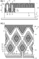
- Figure 1 shows an electronic assembly 11 with a circuit carrier 12 and a component 13 in the form of a power electronic component.
- a cooling device 14 is mounted on the structural component 13, which is shown partially in section in two variants. The two variants are separated from each other by a fault line.
- Both variants have heat pipes 15 which are surrounded by a latent heat storage device 17 in a heat absorption zone 16.
- the heat pipes 15 have heat release zones 18 which are surrounded by a passive cooling structure 19a in the form of ribs (variant shown on the left of the break line).
- a rum grille can also be attached to the heat pipe 15 in the heat emission zone 18 as a passive cooling structure 19b (variant shown on the right).
- the heat pipes 15 are filled with a first phase change medium 20 (depending on the required operating temperature, elementary gases, hydrocarbon compounds and low-melting metals are possible).
- the one variant of the heat pipe shown on the left is designed as a thermosyphon, the liquid first phase change medium 20 collecting in the heat absorption zone 16 and evaporating when heated above the boiling point. It condenses in the heat emission zone 18 and flows back into the heat absorption zone 16 due to the force of gravity.
- the heat pipe 15 can also be designed as a heat pipe.
- the heat pipe 15 is then lined with a capillary wall structure 21, the capillary forces flowing in the capillary channels (not shown) of the capillary wall structure 21 to the heat absorption zone 16 and the evaporating first phase change medium 20 evaporating and flowing to the heat release zone 18.
- the cooling device can also be used in other than the one in Figure 1 mounting position shown can be used.
- the latent heat accumulator 17 is also arranged around the heat absorption zone 16. This is filled with a second phase change medium 22, which remains solid during normal operation of the structural component 13 (depending on the required operating temperature, paraffins, salts or water are used). Both the heat absorption zones 16 of the heat pipes 15 and the latent heat accumulator 17 are arranged in the vicinity of a contact surface 23 of the cooling device 14, which serves as a thermal interface to the structural component 13 functioning as a heat source. In the event of thermal peak loads in the structural component 13 heated the cooling device 14 becomes stronger, so that the second phase change medium 22 begins to melt in the latent heat storage device 17. This reduces the thermal load on the heat pipes 15. So that the heat can be quickly distributed in the second phase change medium 22, a heat conduction structure in the form of a space lattice 24b is provided in the latent heat accumulator 17, which is supported on the inner walls of the latent heat accumulator 17.
- the heat pipe 15 consists of a single contiguous space.
- several sub-spaces 17 a, 17 b, 17 c (and further sub-spaces not shown) are accommodated, which are connected to one another via connecting structures 25.
- the connection structures 25 ensure, on the one hand, that the sub-spaces 17a, 17b, 17c are fixed and can also have connection channels 26 shown in dashed lines.
- the subspaces 17a, 17b, 17c can be filled with the second phase change medium 22 via an opening 27.
- the opening is then closed in a manner not shown.
- the heat pipe 15 is filled with the first phase change medium 20 through a further opening 28 which is also closed in a manner not shown after filling.
- a spatial structure is created that is arranged in the heat pipe 15 in such a way that the heat pipe also forms a spatial structure that is nested with the spatial structure of the latent heat accumulator 17a, 17b, 17c .
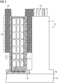
- individually standing heat pipes 15 are shown in the form of heat pipes, in the interior of which the latent heat storage 17 is arranged in the form of a space grid.
- this spatial grid is designed to be hollow, the second phase change medium 22 is housed in the cavity.
- heat conducting structures 24a in the form of ribs can be accommodated in the hollow grid.
- the heat pipes 15 according to Figure 3 also have passive cooling structures in the form of grids 19b and in the form of ribs 19a. As already explained, these passive cooling structures 19a, 19b enable heat to be given off from the heat pipe 15 to the environment.
- FIG. 1 to 4 The ones in the Figures 1 to 4
- the structures shown have a comparatively complex geometry.
- laser melting and / or laser sintering can be used as an additive manufacturing process.
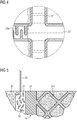
- a laser beam 29 is directed onto a powder bed 30, which is solidified in layers to form the structure of the component.
- the powder of the powder bed 30 remains in the interstices during manufacture. Production takes place in a system suitable for this purpose, which is known per se and therefore in Figure 5 is not shown.
- the laser beam 29 is used to carry out selective laser melting.
- the powder in the powder bed 30 massive component areas with a high density are created.
- the capillary wall structure 21 is with the laser beam 29, as in Figure 5 shown, just made.
- a selective Laser sintering is used, in which the powder is not completely melted, which is why pores 32 remain in the capillary wall structure 21, which are thus formed by an open-pore pore system.
- the porosity can be designed such that it can be produced by a suitable exposure strategy, for example by means of selective laser melting (SLM) or selective laser sintering (SLS).
- SLM selective laser melting
- SLS selective laser sintering
- the pores can be obtained by a defined exposure strategy.
- SLS selective laser melting
- the powder particles sinter with one another, with gaps remaining between the powder particles.
- an exposure strategy can be selected in which the surface of the powder bed is only partially exposed by SLM, so that individual powder particles remain unexposed and are later removed from the workpiece can.
- the pore formation can be generated by a statistically distributed, incomplete exposure of the powder bed, the course of the pores or the exposed region of the respective powder layers being random.
- the incomplete exposure regime follows certain patterns, for example a line spacing during exposure, which is deliberately chosen so large that unexposed and not melted or not melted particles remain between the tracks.
- the desired pores are created in these areas. This can be achieved, for example, by rotating the parallel tracks at regular intervals by, for example, 90 ° during production. Depending on the desired pore size, this change takes place after a certain number of powder layers.
Landscapes
- Engineering & Computer Science (AREA)
- Physics & Mathematics (AREA)
- Thermal Sciences (AREA)
- Microelectronics & Electronic Packaging (AREA)
- Mechanical Engineering (AREA)
- General Engineering & Computer Science (AREA)
- Life Sciences & Earth Sciences (AREA)
- Sustainable Development (AREA)
- Chemical & Material Sciences (AREA)
- Dispersion Chemistry (AREA)
- Cooling Or The Like Of Semiconductors Or Solid State Devices (AREA)
- Cooling Or The Like Of Electrical Apparatus (AREA)
Claims (16)
- Dispositif de refroidissement, comprenant une interface thermique pour au moins une source de chaleur à refroidir, le dispositif de refroidissement ayant, dans des volumes séparés l'un de l'autre, un tube (15) échangeur de chaleur ayant un premier fluide (20) à changement de phase et un accumulateur (17) de chaleur latente ayant un deuxième fluide (22) à changement de phase, dans lequel
la chaleur de la source de chaleur peut être envoyée à l'interface thermique dans une zone d'absorption de la chaleur de l'échangeur (15) de chaleur et le point de fusion du deuxième fluide (22) à changement de phase est plus haut que le point d'évaporation du premier fluide (20) à changement de phase, caractérisé en ce que le tube (15) échangeur de chaleur et l'accumulateur (17) de chaleur latente sont formés de deux structures dans l'espace imbriquées l'une dans l'autre. - Dispositif de refroidissement suivant la revendication 1, dans lequel le point de fusion du deuxième fluide (22) à changement de phase de moins de 20 K, de préférence de moins de 10 K, plus haut que le point (20) d'évaporation du premier fluide à changement de phase.
- Dispositif de refroidissement suivant la revendication 1, dans lequel l'accumulateur (17) de chaleur latente est formé d'un réseau spatial creux, dans lequel• le deuxième fluide (22) à changement de phase est enfermé dans un espace creux formé dans le réseau spatial comme accumulateur (17) de chaleur latente et• le premier fluide (20) à changement de phase est logé dans des espaces intermédiaires de réseau formés par le réseau.
- Dispositif de refroidissement suivant l'une des revendications 1 ou 2, dans lequel l'accumulateur de chaleur latente a une pluralité d'espaces (17a, 17b, 17c) partiels, qui sont maintenus dans le tube (15) échangeur de chaleur.
- Dispositif de refroidissement suivant la revendication 4, dans lequel les espaces (17a, 17b, 17c) partiels communiquent entre eux fluidiquement.
- Dispositif de refroidissement suivant l'une des revendications 1 ou 2, dans lequel il est prévu plusieurs tubes (15) échangeurs de chaleur, qui sont entourés de l'accumulateur (17) de chaleur latente.
- Dispositif de refroidissement suivant l'une des revendications précédentes, dans lequel le au moins un tube (15) échangeur de chaleur est pourvu, dans une zone (18) de cession de chaleur à l'extérieur, d'une structure (19a, 19b) passive de refroidissement.
- Dispositif de refroidissement suivant la revendication 7, dans lequel la structure (19a, 19b) passive de refroidissement a des nervures et/ou un réseau spatial.
- Dispositif de refroidissement suivant l'une des revendications précédentes, dans lequel le au moins un tube (15) échangeur de chaleur est réalisé sous la forme d'un heatpipe en une pièce en ayant une structure (21) de paroi capillaire.
- Dispositif de refroidissement suivant l'une des revendications précédentes, dans lequel, dans l'accumulateur (17) de chaleur latente, est disposée une structure (24a, 24b) de conduction de la chaleur, qui est reliée à la paroi de l'accumulateur (17) de chaleur latente.
- Dispositif de refroidissement suivant la revendication 10, dans lequel la structure (24a, 24b) conductrice de la chaleur a des nervures et/ou un réseau spatial.
- Circuit électronique, comprenant un composant (13) à refroidir, le composant (13) étant relié à l'interface thermique d'un dispositif (14) de refroidissement suivant l'une des revendications précédentes.
- Circuit électronique suivant la revendication 12, dans lequel la puissance de refroidissement possible au maximum du tube (15) échangeur de chaleur du dispositif (14) de refroidissement• est supérieure ou égale à la puissance calorifique du composant (13) à la charge nominale, mais• plus petite que la puissance calorifique du composant (13) à une charge de pointe autorisée.
- Procédé de fabrication d'un dispositif (14) de refroidissement suivant l'une des revendications 1 à 11, dans lequel on utilise pour la fabrication un procédé de fabrication additif, notamment une fusion laser ou une combinaison d'un frittage laser et d'une fusion laser.
- Dispositif de refroidissement suivant l'une des revendications 1 à 11, dans lequel celui-ci est fabriqué par un procédé de fabrication additif, notamment par une fusion laser ou une combinaison d'un frittage laser et d'une fusion laser.
- Dispositif de refroidissement suivant la revendication 15, dans lequel celui-ci est fabriqué en une seule pièce.
Applications Claiming Priority (2)
| Application Number | Priority Date | Filing Date | Title |
|---|---|---|---|
| DE102017200524.6A DE102017200524A1 (de) | 2017-01-13 | 2017-01-13 | Kühlvorrichtung mit einem Wärmerohr und einem Latentwärmespeicher, Verfahren zum Herstellen derselben und elektronische Schaltung |
| PCT/EP2017/082958 WO2018130367A1 (fr) | 2017-01-13 | 2017-12-15 | Dispositif de refroidissement comprenant un caloduc et un accumulateur de chaleur latente, procédé de fabrication de celui-ci et circuit électronique |
Publications (2)
| Publication Number | Publication Date |
|---|---|
| EP3551955A1 EP3551955A1 (fr) | 2019-10-16 |
| EP3551955B1 true EP3551955B1 (fr) | 2020-09-09 |
Family
ID=61132374
Family Applications (1)
| Application Number | Title | Priority Date | Filing Date |
|---|---|---|---|
| EP17837867.5A Active EP3551955B1 (fr) | 2017-01-13 | 2017-12-15 | Dispositif de refroidissement comprenant un caloduc et un accumulateur de chaleur latente, procédé de fabrication de celui-ci et circuit électronique |
Country Status (5)
| Country | Link |
|---|---|
| US (1) | US20190368822A1 (fr) |
| EP (1) | EP3551955B1 (fr) |
| CN (1) | CN110192076A (fr) |
| DE (1) | DE102017200524A1 (fr) |
| WO (1) | WO2018130367A1 (fr) |
Families Citing this family (16)
| Publication number | Priority date | Publication date | Assignee | Title |
|---|---|---|---|---|
| US20200109901A1 (en) * | 2018-10-03 | 2020-04-09 | Raytheon Company | Additively manufactured thermal energy storage units |
| EP3726708A1 (fr) * | 2019-04-16 | 2020-10-21 | Siemens Aktiengesellschaft | Dispositif redresseur, son procédé de fabrication et excitatrice |
| US10641556B1 (en) * | 2019-04-26 | 2020-05-05 | United Arab Emirates University | Heat sink with condensing fins and phase change material |
| EP3736519A1 (fr) * | 2019-05-08 | 2020-11-11 | Siemens Aktiengesellschaft | Dispositif d'évaporateur-condensateur |
| KR102603213B1 (ko) * | 2019-09-02 | 2023-11-16 | 현대자동차주식회사 | 전력 반도체용 냉각 장치 및 그 제조 방법 |
| CN110534490B (zh) * | 2019-09-10 | 2021-01-12 | 西安交通大学深圳研究院 | 一种垂直方向上具有梯度的强化沸腾换热微结构及其制造方法 |
| DE102019132111A1 (de) * | 2019-11-27 | 2021-05-27 | Vaillant Gmbh | Schichtweise aufgebauter thermischer Speicher |
| IT202000008386A1 (it) * | 2020-04-20 | 2021-10-20 | Prima Ind Spa | Terminale operativo laser, macchina operatrice laser e procedimento di fabbricazione corrispondenti |
| CN112872359A (zh) * | 2021-01-11 | 2021-06-01 | 上海交通大学 | 一种激光表面熔覆的金属热管材料及其制备方法 |
| DE102021104769A1 (de) | 2021-02-26 | 2022-09-01 | Klaus-Dietmar Lamprecht | Verkapselung für PCM-Wärmespeicher mit verbessertem Wärmeaustausch |
| EP4348756B1 (fr) * | 2021-05-24 | 2026-05-06 | Beam Global | Composite à changement de phase intelligent pour gestion thermique passive |
| EP4130631B1 (fr) * | 2021-08-05 | 2024-10-02 | Abb Schweiz Ag | Procédé et contrôleur pour tester un dispositif de refroidissement à deux phases, programme informatique et support lisible par ordinateur |
| CN114001573A (zh) * | 2021-11-30 | 2022-02-01 | 华能营口热电有限责任公司 | 一种利用介质相变实现流体温度控制的换热装置及方法 |
| US12188726B2 (en) * | 2022-08-30 | 2025-01-07 | United Arab Emirates University | Heat sink with opposed elements providing temperature gradient |
| US20250044037A1 (en) * | 2023-08-01 | 2025-02-06 | Rocky Research | Systems and techniques for dissipating heat |
| FR3154171A1 (fr) * | 2023-10-12 | 2025-04-18 | Psa Automobiles Sa | Echangeur de chaleur a caloducs pour turbomachine dans un vehicule automobile |
Family Cites Families (23)
| Publication number | Priority date | Publication date | Assignee | Title |
|---|---|---|---|---|
| DE4230583A1 (de) * | 1992-09-12 | 1994-03-17 | Bayerische Motoren Werke Ag | Elektrische Speicherbatterie, insbesondere für einen Fahrzeug-Antrieb |
| DE19815777A1 (de) * | 1998-04-08 | 1999-10-14 | Modine Mfg Co | Wärmespeicher, insbesondere Latentwärmespeicher |
| KR20000051265A (ko) * | 1999-01-20 | 2000-08-16 | 김영환 | 상변화 물질을 이용한 히트파이프 장치 |
| DE10114998A1 (de) * | 2000-06-08 | 2002-02-21 | Merck Patent Gmbh | Einsatz von PCM in Kühlern für elektronische Batterie |
| US6631755B1 (en) * | 2002-07-17 | 2003-10-14 | Compal Electronics, Inc. | Thermal module with temporary heat storage |
| US6889755B2 (en) * | 2003-02-18 | 2005-05-10 | Thermal Corp. | Heat pipe having a wick structure containing phase change materials |
| DE10347518A1 (de) * | 2003-10-13 | 2005-05-25 | Siemens Ag | Elektronisches Bauelement, Schaltungsträgeraufbau und Elektronikeinheit mit Wärmespeicher |
| US7505269B1 (en) * | 2007-10-11 | 2009-03-17 | Valere Power Inc. | Thermal energy storage transfer system |
| US20090109623A1 (en) * | 2007-10-31 | 2009-04-30 | Forcecon Technology Co., Ltd. | Heat-radiating module with composite phase-change heat-radiating efficiency |
| CN201252709Y (zh) * | 2008-05-28 | 2009-06-03 | 郑州大学 | 热管与相变材料联合热控装置 |
| FR2938323B1 (fr) * | 2008-11-12 | 2010-12-24 | Astrium Sas | Dispositif de regulation thermique a reseau de caloducs capillaires interconnectes |
| DE102009006788A1 (de) | 2009-01-30 | 2010-08-12 | Tutech Innovation Gmbh | Wärmespeicher mit einem Phasenwechselmaterial und Verfahren zu dessen Herstellung |
| DE102009058842B4 (de) * | 2009-12-18 | 2022-01-27 | Vitesco Technologies GmbH | Fahrzeug mit Temperierungsvorrichtung, Batterie mit Latentwärmespeicher und Verfahren zum Temperieren von Fahrzeugen |
| US20140090808A1 (en) * | 2011-05-17 | 2014-04-03 | Sharp Kabushiki Kaisha | Heat-transfer device |
| DE102012020958A1 (de) * | 2012-10-25 | 2014-04-30 | Volkswagen Aktiengesellschaft | Kühleinrichtung zur Kühlung einer elektrischen Maschine sowie elektrische Maschine mit einer solchen |
| DE102012112646A1 (de) * | 2012-12-19 | 2014-06-26 | Rittal Gmbh & Co. Kg | PCM Speicher |
| DE102013217829A1 (de) | 2013-09-06 | 2015-03-12 | Siemens Aktiengesellschaft | Integriertes Schaltungssystem mit einer ein Latentwärme-Speichermedium nutzenden Kühlvorrichtung |
| WO2016074918A1 (fr) * | 2014-11-11 | 2016-05-19 | Basf Se | Dispositif thermoélectrique |
| US9476651B2 (en) * | 2014-12-15 | 2016-10-25 | General Electric Company | Thermal management system |
| DE202015004833U1 (de) | 2015-07-07 | 2015-10-05 | Seong-Hyun Cho | Einrichtung zur Kühlung eines netzunabhängigen technisch genutzten Innenraumes |
| CN105841536B (zh) * | 2016-03-28 | 2018-02-27 | 沧州渤海新区元大自然能源有限公司 | 一种复合蓄热体及制备方法 |
| EP3240372A1 (fr) * | 2016-04-27 | 2017-11-01 | AT & S Austria Technologie & Systemtechnik Aktiengesellschaft | Support de composant capacitif de chaleur et procédé pour produire ce composant support |
| US10262920B1 (en) * | 2016-12-05 | 2019-04-16 | Xilinx, Inc. | Stacked silicon package having a thermal capacitance element |
-
2017
- 2017-01-13 DE DE102017200524.6A patent/DE102017200524A1/de not_active Withdrawn
- 2017-12-15 WO PCT/EP2017/082958 patent/WO2018130367A1/fr not_active Ceased
- 2017-12-15 EP EP17837867.5A patent/EP3551955B1/fr active Active
- 2017-12-15 US US16/477,625 patent/US20190368822A1/en not_active Abandoned
- 2017-12-15 CN CN201780082939.9A patent/CN110192076A/zh active Pending
Non-Patent Citations (1)
| Title |
|---|
| None * |
Also Published As
| Publication number | Publication date |
|---|---|
| WO2018130367A1 (fr) | 2018-07-19 |
| DE102017200524A1 (de) | 2018-07-19 |
| CN110192076A (zh) | 2019-08-30 |
| EP3551955A1 (fr) | 2019-10-16 |
| US20190368822A1 (en) | 2019-12-05 |
Similar Documents
| Publication | Publication Date | Title |
|---|---|---|
| EP3551955B1 (fr) | Dispositif de refroidissement comprenant un caloduc et un accumulateur de chaleur latente, procédé de fabrication de celui-ci et circuit électronique | |
| DE102006008786B4 (de) | Adsorptions-Wärmepumpe, Adsorptions-Kältemaschine und darin enthaltene Adsorberelemente auf Basis eines offenporigen wärmeleitenden Festkörpers | |
| EP2511030B1 (fr) | Procédé de fabrication d'un composant doté d'au moins un élément de construction agencé dans le composant et composant doté d'au moins un élément de construction | |
| DE102020200061A1 (de) | Ultradünne zweiphasen-wärmetauscher mit strukturdocht | |
| DE3617762C2 (de) | Mit Kapillareffekt arbeitender Wärmetauscher für ein thermisches Betriebssystem | |
| DE102015215570A1 (de) | Kühlkörper für eine elektronische Komponente und Verfahren zu deren Herstellung | |
| DE112018003831T5 (de) | Ultradünne wärmetauscher für das wärmemanagement | |
| EP2304371A1 (fr) | Dispositif et procédé pour refroidir des composants au moyen de matériau à changement de phase magnétisable | |
| EP2236970B1 (fr) | Accumulateur thermique doté d'un matériau à changement de phase et son procédé de fabrication | |
| EP2832456B1 (fr) | Sonotrode doté d'un dispositif de refroidissement intégré | |
| EP3698400B1 (fr) | Procédé de fabrication d'un dissipateur thermique sur un module électronique | |
| DE112004002839T5 (de) | Vorrichtung für den Wärmetransport und Verfahren zu dessen Herstellung | |
| DE2235792A1 (de) | Vorrichtung zur uebertragung von waermeenergie | |
| DE102013002847A1 (de) | Batterieanordnung für ein Fahrzeug und Verfahren zum Betreiben einer Batterieanordnung | |
| DE102015112395A1 (de) | Form | |
| WO2014166621A1 (fr) | Centrage d'une plaque dans un support tant à température ambiante qu'à des températures plus élevées | |
| DE102015215571A1 (de) | Kühlkörper für eine elektronische Komponente und Verfahren zu dessen Herstellung | |
| DE102005004695B3 (de) | Kühlkörper für elektrische Bauelemente | |
| DE102020204498A1 (de) | Bremssattel für eine Scheibenbremse für ein Fahrzeug und Verfahren zum Herstellen eines Bremssattels | |
| DE102022111460A1 (de) | Batterieanordnung mit Kapillaranordnungen | |
| DE102016214959B4 (de) | Temperiereinheit für ein elektronisches Bauelement und Verfahren zu dessen Herstellung | |
| DE102016214965A1 (de) | Temperiereinheit für einen Schaltungsträger, Verfahren zu deren Herstellung sowie Verfahren zum Bestimmen der Geometrie einer Temperiereinheit | |
| DE69713547T2 (de) | Kryostat für Tiefsttemperatur-Kälteanlage und Kälteanlagen mit einem solchen Kryostat | |
| DE3536749A1 (de) | Laservorrichtung | |
| DE102015208095B4 (de) | Anode für Röntgenröhre und Verfahren zur Herstellung einer Anode |
Legal Events
| Date | Code | Title | Description |
|---|---|---|---|
| STAA | Information on the status of an ep patent application or granted ep patent |
Free format text: STATUS: UNKNOWN |
|
| STAA | Information on the status of an ep patent application or granted ep patent |
Free format text: STATUS: THE INTERNATIONAL PUBLICATION HAS BEEN MADE |
|
| PUAI | Public reference made under article 153(3) epc to a published international application that has entered the european phase |
Free format text: ORIGINAL CODE: 0009012 |
|
| STAA | Information on the status of an ep patent application or granted ep patent |
Free format text: STATUS: REQUEST FOR EXAMINATION WAS MADE |
|
| 17P | Request for examination filed |
Effective date: 20190709 |
|
| AK | Designated contracting states |
Kind code of ref document: A1 Designated state(s): AL AT BE BG CH CY CZ DE DK EE ES FI FR GB GR HR HU IE IS IT LI LT LU LV MC MK MT NL NO PL PT RO RS SE SI SK SM TR |
|
| AX | Request for extension of the european patent |
Extension state: BA ME |
|
| DAV | Request for validation of the european patent (deleted) | ||
| DAX | Request for extension of the european patent (deleted) | ||
| GRAP | Despatch of communication of intention to grant a patent |
Free format text: ORIGINAL CODE: EPIDOSNIGR1 |
|
| STAA | Information on the status of an ep patent application or granted ep patent |
Free format text: STATUS: GRANT OF PATENT IS INTENDED |
|
| INTG | Intention to grant announced |
Effective date: 20200512 |
|
| GRAS | Grant fee paid |
Free format text: ORIGINAL CODE: EPIDOSNIGR3 |
|
| GRAA | (expected) grant |
Free format text: ORIGINAL CODE: 0009210 |
|
| STAA | Information on the status of an ep patent application or granted ep patent |
Free format text: STATUS: THE PATENT HAS BEEN GRANTED |
|
| AK | Designated contracting states |
Kind code of ref document: B1 Designated state(s): AL AT BE BG CH CY CZ DE DK EE ES FI FR GB GR HR HU IE IS IT LI LT LU LV MC MK MT NL NO PL PT RO RS SE SI SK SM TR |
|
| REG | Reference to a national code |
Ref country code: GB Ref legal event code: FG4D Free format text: NOT ENGLISH |
|
| REG | Reference to a national code |
Ref country code: AT Ref legal event code: REF Ref document number: 1312098 Country of ref document: AT Kind code of ref document: T Effective date: 20200915 Ref country code: CH Ref legal event code: EP |
|
| REG | Reference to a national code |
Ref country code: DE Ref legal event code: R096 Ref document number: 502017007242 Country of ref document: DE |
|
| REG | Reference to a national code |
Ref country code: CH Ref legal event code: NV Representative=s name: SIEMENS SCHWEIZ AG, CH Ref country code: IE Ref legal event code: FG4D Free format text: LANGUAGE OF EP DOCUMENT: GERMAN |
|
| REG | Reference to a national code |
Ref country code: NL Ref legal event code: FP |
|
| REG | Reference to a national code |
Ref country code: LT Ref legal event code: MG4D |
|
| PG25 | Lapsed in a contracting state [announced via postgrant information from national office to epo] |
Ref country code: HR Free format text: LAPSE BECAUSE OF FAILURE TO SUBMIT A TRANSLATION OF THE DESCRIPTION OR TO PAY THE FEE WITHIN THE PRESCRIBED TIME-LIMIT Effective date: 20200909 Ref country code: SE Free format text: LAPSE BECAUSE OF FAILURE TO SUBMIT A TRANSLATION OF THE DESCRIPTION OR TO PAY THE FEE WITHIN THE PRESCRIBED TIME-LIMIT Effective date: 20200909 Ref country code: NO Free format text: LAPSE BECAUSE OF FAILURE TO SUBMIT A TRANSLATION OF THE DESCRIPTION OR TO PAY THE FEE WITHIN THE PRESCRIBED TIME-LIMIT Effective date: 20201209 Ref country code: BG Free format text: LAPSE BECAUSE OF FAILURE TO SUBMIT A TRANSLATION OF THE DESCRIPTION OR TO PAY THE FEE WITHIN THE PRESCRIBED TIME-LIMIT Effective date: 20201209 Ref country code: FI Free format text: LAPSE BECAUSE OF FAILURE TO SUBMIT A TRANSLATION OF THE DESCRIPTION OR TO PAY THE FEE WITHIN THE PRESCRIBED TIME-LIMIT Effective date: 20200909 Ref country code: LT Free format text: LAPSE BECAUSE OF FAILURE TO SUBMIT A TRANSLATION OF THE DESCRIPTION OR TO PAY THE FEE WITHIN THE PRESCRIBED TIME-LIMIT Effective date: 20200909 Ref country code: GR Free format text: LAPSE BECAUSE OF FAILURE TO SUBMIT A TRANSLATION OF THE DESCRIPTION OR TO PAY THE FEE WITHIN THE PRESCRIBED TIME-LIMIT Effective date: 20201210 |
|
| PGFP | Annual fee paid to national office [announced via postgrant information from national office to epo] |
Ref country code: FR Payment date: 20201217 Year of fee payment: 4 |
|
| PG25 | Lapsed in a contracting state [announced via postgrant information from national office to epo] |
Ref country code: LV Free format text: LAPSE BECAUSE OF FAILURE TO SUBMIT A TRANSLATION OF THE DESCRIPTION OR TO PAY THE FEE WITHIN THE PRESCRIBED TIME-LIMIT Effective date: 20200909 Ref country code: PL Free format text: LAPSE BECAUSE OF FAILURE TO SUBMIT A TRANSLATION OF THE DESCRIPTION OR TO PAY THE FEE WITHIN THE PRESCRIBED TIME-LIMIT Effective date: 20200909 Ref country code: RS Free format text: LAPSE BECAUSE OF FAILURE TO SUBMIT A TRANSLATION OF THE DESCRIPTION OR TO PAY THE FEE WITHIN THE PRESCRIBED TIME-LIMIT Effective date: 20200909 |
|
| PGFP | Annual fee paid to national office [announced via postgrant information from national office to epo] |
Ref country code: NL Payment date: 20201202 Year of fee payment: 4 |
|
| PG25 | Lapsed in a contracting state [announced via postgrant information from national office to epo] |
Ref country code: SM Free format text: LAPSE BECAUSE OF FAILURE TO SUBMIT A TRANSLATION OF THE DESCRIPTION OR TO PAY THE FEE WITHIN THE PRESCRIBED TIME-LIMIT Effective date: 20200909 Ref country code: CZ Free format text: LAPSE BECAUSE OF FAILURE TO SUBMIT A TRANSLATION OF THE DESCRIPTION OR TO PAY THE FEE WITHIN THE PRESCRIBED TIME-LIMIT Effective date: 20200909 Ref country code: PT Free format text: LAPSE BECAUSE OF FAILURE TO SUBMIT A TRANSLATION OF THE DESCRIPTION OR TO PAY THE FEE WITHIN THE PRESCRIBED TIME-LIMIT Effective date: 20210111 Ref country code: RO Free format text: LAPSE BECAUSE OF FAILURE TO SUBMIT A TRANSLATION OF THE DESCRIPTION OR TO PAY THE FEE WITHIN THE PRESCRIBED TIME-LIMIT Effective date: 20200909 Ref country code: EE Free format text: LAPSE BECAUSE OF FAILURE TO SUBMIT A TRANSLATION OF THE DESCRIPTION OR TO PAY THE FEE WITHIN THE PRESCRIBED TIME-LIMIT Effective date: 20200909 |
|
| PG25 | Lapsed in a contracting state [announced via postgrant information from national office to epo] |
Ref country code: IS Free format text: LAPSE BECAUSE OF FAILURE TO SUBMIT A TRANSLATION OF THE DESCRIPTION OR TO PAY THE FEE WITHIN THE PRESCRIBED TIME-LIMIT Effective date: 20210109 Ref country code: ES Free format text: LAPSE BECAUSE OF FAILURE TO SUBMIT A TRANSLATION OF THE DESCRIPTION OR TO PAY THE FEE WITHIN THE PRESCRIBED TIME-LIMIT Effective date: 20200909 Ref country code: AL Free format text: LAPSE BECAUSE OF FAILURE TO SUBMIT A TRANSLATION OF THE DESCRIPTION OR TO PAY THE FEE WITHIN THE PRESCRIBED TIME-LIMIT Effective date: 20200909 |
|
| REG | Reference to a national code |
Ref country code: DE Ref legal event code: R097 Ref document number: 502017007242 Country of ref document: DE |
|
| PG25 | Lapsed in a contracting state [announced via postgrant information from national office to epo] |
Ref country code: SK Free format text: LAPSE BECAUSE OF FAILURE TO SUBMIT A TRANSLATION OF THE DESCRIPTION OR TO PAY THE FEE WITHIN THE PRESCRIBED TIME-LIMIT Effective date: 20200909 |
|
| REG | Reference to a national code |
Ref country code: DE Ref legal event code: R119 Ref document number: 502017007242 Country of ref document: DE |
|
| PLBE | No opposition filed within time limit |
Free format text: ORIGINAL CODE: 0009261 |
|
| STAA | Information on the status of an ep patent application or granted ep patent |
Free format text: STATUS: NO OPPOSITION FILED WITHIN TIME LIMIT |
|
| REG | Reference to a national code |
Ref country code: CH Ref legal event code: PL |
|
| 26N | No opposition filed |
Effective date: 20210610 |
|
| PG25 | Lapsed in a contracting state [announced via postgrant information from national office to epo] |
Ref country code: SI Free format text: LAPSE BECAUSE OF FAILURE TO SUBMIT A TRANSLATION OF THE DESCRIPTION OR TO PAY THE FEE WITHIN THE PRESCRIBED TIME-LIMIT Effective date: 20200909 Ref country code: DK Free format text: LAPSE BECAUSE OF FAILURE TO SUBMIT A TRANSLATION OF THE DESCRIPTION OR TO PAY THE FEE WITHIN THE PRESCRIBED TIME-LIMIT Effective date: 20200909 Ref country code: MC Free format text: LAPSE BECAUSE OF FAILURE TO SUBMIT A TRANSLATION OF THE DESCRIPTION OR TO PAY THE FEE WITHIN THE PRESCRIBED TIME-LIMIT Effective date: 20200909 |
|
| REG | Reference to a national code |
Ref country code: BE Ref legal event code: MM Effective date: 20201231 |
|
| PG25 | Lapsed in a contracting state [announced via postgrant information from national office to epo] |
Ref country code: IE Free format text: LAPSE BECAUSE OF NON-PAYMENT OF DUE FEES Effective date: 20201215 Ref country code: IT Free format text: LAPSE BECAUSE OF FAILURE TO SUBMIT A TRANSLATION OF THE DESCRIPTION OR TO PAY THE FEE WITHIN THE PRESCRIBED TIME-LIMIT Effective date: 20200909 Ref country code: LU Free format text: LAPSE BECAUSE OF NON-PAYMENT OF DUE FEES Effective date: 20201215 |
|
| PG25 | Lapsed in a contracting state [announced via postgrant information from national office to epo] |
Ref country code: DE Free format text: LAPSE BECAUSE OF NON-PAYMENT OF DUE FEES Effective date: 20210701 Ref country code: CH Free format text: LAPSE BECAUSE OF NON-PAYMENT OF DUE FEES Effective date: 20201231 Ref country code: LI Free format text: LAPSE BECAUSE OF NON-PAYMENT OF DUE FEES Effective date: 20201231 |
|
| PG25 | Lapsed in a contracting state [announced via postgrant information from national office to epo] |
Ref country code: TR Free format text: LAPSE BECAUSE OF FAILURE TO SUBMIT A TRANSLATION OF THE DESCRIPTION OR TO PAY THE FEE WITHIN THE PRESCRIBED TIME-LIMIT Effective date: 20200909 Ref country code: MT Free format text: LAPSE BECAUSE OF FAILURE TO SUBMIT A TRANSLATION OF THE DESCRIPTION OR TO PAY THE FEE WITHIN THE PRESCRIBED TIME-LIMIT Effective date: 20200909 Ref country code: CY Free format text: LAPSE BECAUSE OF FAILURE TO SUBMIT A TRANSLATION OF THE DESCRIPTION OR TO PAY THE FEE WITHIN THE PRESCRIBED TIME-LIMIT Effective date: 20200909 |
|
| PG25 | Lapsed in a contracting state [announced via postgrant information from national office to epo] |
Ref country code: MK Free format text: LAPSE BECAUSE OF FAILURE TO SUBMIT A TRANSLATION OF THE DESCRIPTION OR TO PAY THE FEE WITHIN THE PRESCRIBED TIME-LIMIT Effective date: 20200909 |
|
| PG25 | Lapsed in a contracting state [announced via postgrant information from national office to epo] |
Ref country code: BE Free format text: LAPSE BECAUSE OF NON-PAYMENT OF DUE FEES Effective date: 20201231 |
|
| REG | Reference to a national code |
Ref country code: NL Ref legal event code: MM Effective date: 20220101 |
|
| GBPC | Gb: european patent ceased through non-payment of renewal fee |
Effective date: 20211215 |
|
| PG25 | Lapsed in a contracting state [announced via postgrant information from national office to epo] |
Ref country code: NL Free format text: LAPSE BECAUSE OF NON-PAYMENT OF DUE FEES Effective date: 20220101 |
|
| PG25 | Lapsed in a contracting state [announced via postgrant information from national office to epo] |
Ref country code: GB Free format text: LAPSE BECAUSE OF NON-PAYMENT OF DUE FEES Effective date: 20211215 |
|
| PG25 | Lapsed in a contracting state [announced via postgrant information from national office to epo] |
Ref country code: FR Free format text: LAPSE BECAUSE OF NON-PAYMENT OF DUE FEES Effective date: 20211231 |
|
| REG | Reference to a national code |
Ref country code: AT Ref legal event code: MM01 Ref document number: 1312098 Country of ref document: AT Kind code of ref document: T Effective date: 20221215 |
|
| PG25 | Lapsed in a contracting state [announced via postgrant information from national office to epo] |
Ref country code: AT Free format text: LAPSE BECAUSE OF NON-PAYMENT OF DUE FEES Effective date: 20221215 |
|
| PG25 | Lapsed in a contracting state [announced via postgrant information from national office to epo] |
Ref country code: AT Free format text: LAPSE BECAUSE OF NON-PAYMENT OF DUE FEES Effective date: 20221215 |
|
| PGFP | Annual fee paid to national office [announced via postgrant information from national office to epo] |
Ref country code: AT Payment date: 20260410 Year of fee payment: 5 |