EP3551818B1 - Système pour carreler et méthode utilisant ce système - Google Patents
Système pour carreler et méthode utilisant ce système Download PDFInfo
- Publication number
- EP3551818B1 EP3551818B1 EP17826448.7A EP17826448A EP3551818B1 EP 3551818 B1 EP3551818 B1 EP 3551818B1 EP 17826448 A EP17826448 A EP 17826448A EP 3551818 B1 EP3551818 B1 EP 3551818B1
- Authority
- EP
- European Patent Office
- Prior art keywords
- tile
- adhesive
- nozzle
- robot
- apertures
- Prior art date
- Legal status (The legal status is an assumption and is not a legal conclusion. Google has not performed a legal analysis and makes no representation as to the accuracy of the status listed.)
- Active
Links
Images
Classifications
-
- E—FIXED CONSTRUCTIONS
- E04—BUILDING
- E04F—FINISHING WORK ON BUILDINGS, e.g. STAIRS, FLOORS
- E04F21/00—Implements for finishing work on buildings
- E04F21/02—Implements for finishing work on buildings for applying plasticised masses to surfaces, e.g. plastering walls
- E04F21/023—Implements for finishing work on buildings for applying plasticised masses to surfaces, e.g. plastering walls for applying adhesive, e.g. glue or mortar, on the covering elements, in particular tiles
-
- B—PERFORMING OPERATIONS; TRANSPORTING
- B05—SPRAYING OR ATOMISING IN GENERAL; APPLYING FLUENT MATERIALS TO SURFACES, IN GENERAL
- B05C—APPARATUS FOR APPLYING FLUENT MATERIALS TO SURFACES, IN GENERAL
- B05C13/00—Means for manipulating or holding work, e.g. for separate articles
- B05C13/02—Means for manipulating or holding work, e.g. for separate articles for particular articles
-
- B—PERFORMING OPERATIONS; TRANSPORTING
- B05—SPRAYING OR ATOMISING IN GENERAL; APPLYING FLUENT MATERIALS TO SURFACES, IN GENERAL
- B05C—APPARATUS FOR APPLYING FLUENT MATERIALS TO SURFACES, IN GENERAL
- B05C5/00—Apparatus in which liquid or other fluent material is projected, poured or allowed to flow on to the surface of the work
- B05C5/02—Apparatus in which liquid or other fluent material is projected, poured or allowed to flow on to the surface of the work the liquid or other fluent material being discharged through an outlet orifice by pressure, e.g. from an outlet device in contact or almost in contact, with the work
- B05C5/0208—Apparatus in which liquid or other fluent material is projected, poured or allowed to flow on to the surface of the work the liquid or other fluent material being discharged through an outlet orifice by pressure, e.g. from an outlet device in contact or almost in contact, with the work for applying liquid or other fluent material to separate articles
- B05C5/0212—Apparatus in which liquid or other fluent material is projected, poured or allowed to flow on to the surface of the work the liquid or other fluent material being discharged through an outlet orifice by pressure, e.g. from an outlet device in contact or almost in contact, with the work for applying liquid or other fluent material to separate articles only at particular parts of the articles
- B05C5/0216—Apparatus in which liquid or other fluent material is projected, poured or allowed to flow on to the surface of the work the liquid or other fluent material being discharged through an outlet orifice by pressure, e.g. from an outlet device in contact or almost in contact, with the work for applying liquid or other fluent material to separate articles only at particular parts of the articles by relative movement of article and outlet according to a predetermined path
-
- B—PERFORMING OPERATIONS; TRANSPORTING
- B25—HAND TOOLS; PORTABLE POWER-DRIVEN TOOLS; MANIPULATORS
- B25J—MANIPULATORS; CHAMBERS PROVIDED WITH MANIPULATION DEVICES
- B25J11/00—Manipulators not otherwise provided for
-
- B—PERFORMING OPERATIONS; TRANSPORTING
- B25—HAND TOOLS; PORTABLE POWER-DRIVEN TOOLS; MANIPULATORS
- B25J—MANIPULATORS; CHAMBERS PROVIDED WITH MANIPULATION DEVICES
- B25J11/00—Manipulators not otherwise provided for
- B25J11/005—Manipulators for mechanical processing tasks
-
- E—FIXED CONSTRUCTIONS
- E04—BUILDING
- E04F—FINISHING WORK ON BUILDINGS, e.g. STAIRS, FLOORS
- E04F21/00—Implements for finishing work on buildings
- E04F21/18—Implements for finishing work on buildings for setting wall or ceiling slabs or plates
- E04F21/1805—Ceiling panel lifting devices
- E04F21/1822—Ceiling panel lifting devices with pivotally mounted arms
-
- E—FIXED CONSTRUCTIONS
- E04—BUILDING
- E04F—FINISHING WORK ON BUILDINGS, e.g. STAIRS, FLOORS
- E04F21/00—Implements for finishing work on buildings
- E04F21/20—Implements for finishing work on buildings for laying flooring
Definitions
- the present invention relates to a system for tiling a surface and a method of using such system.
- tile adhesive either manually or via a screw pump and nozzle on the surface to be tiled.
- covering a floor or wall surface with ceramic tiles (“tiling") is performed manually by a specialised tiler (paver).
- tiling is a physically hard and time-consuming task which needs much expertise. If a tiling job is not performed correctly, uneven or irregular tile surfaces result which (in particular for aesthetic reasons) are often not acceptable and have to be repaired or fully replaced. Repairing or replacing a tiled surface is, again, very laborious, generates a lot of dust and is comparatively expensive.
- WO 99/56888 A1 discloses a portable adhesive applicator apparatus for articles to which adhesive is to be applied, wherein the articles may be parquet panels, ceramic tiles and the like. It is generally mentioned that the adhesive may be applied directly to the underside of a parquet panel.
- a pusher means pushes the parquet panel under nozzles wherein an adhesive pump is activated when the parquet panel touches an activating means in the form of, e. g. a micro switch under the adhesive nozzles, so that the adhesive exits the nozzles whilst the pusher means pushes the parquet panel against an end switch.
- EP 1 598 502 A2 discloses a tile coating apparatus for flooring.
- the apparatus has a self-supporting frame, preferably equipped with rollers for moving the same to a required flooring location, and assembled thereto it comprises the combination of an adhesive holding tank housing a dispenser rod arranged in the semicylindrical tank bottom, tile transfer means, tile stacking means and driving means. By means of a suitable transfer and guiding means another tile (of a stack) is transferred in a horizontal direction so as to pass underneath the coating dispensing unit filled with adhesive.
- U1 discloses an application device with a nozzle assembly, wherein an adhesive material is applied on an adhesive side of a tile of similar plate.
- a mixing container, a nozzle, a conveyor belt, a tile transporting unit, and a motor unit are provided.
- the back side of a tile is arranged under a nozzle head rod, wherein the tile is transported by a conveyor belt.
- BE 101 5401 A3 discloses an applicator including a system for applying one or more predetermined dosed amounts of bonding agent.
- the dosing system comprises a pump connected to one or more sealable hoses.
- EP 2 610 417 A1 discloses a robot for delivering and spreading more adhesive material on a floor and another robot to pick up the tiles and accurately place them over an area treated with adhesive material.
- a core idea of the invention is an automated supply of tile adhesive (mortar) on a surface (back side) of a tile, in particular via a robot.
- the adhesive may be placed on the surface (back side) of the tiles by an (extruding) nozzle.
- the adhesive mixed (mixable) with an accelerator at the nozzle to accelerate the process of setting.
- an accelerator at the nozzle to accelerate the process of setting.
- This improves the speed and quality of the tiling process and also reduces costs.
- an improved system for applying a tile adhesive is obtained.
- the supporting and moving device can be configured so that the tile is moved during emergence of tile adhesive from the nozzle (wherein the nozzle may stand still).
- the nozzle may be moved (wherein the tile may stand still).
- the robot may comprise one, two or more robot arms (which can be configured to move in any direction of the three-dimensional space).
- the automated supporting and moving device may contain a control device and/or a (electronic) memory device and/or determination (sensor) means for determination of a position of the tile with respect to the nozzle.
- the automated supporting and moving device is in particular configured so that the tile is supported and positioned with respect to the nozzle (during emergence of the tile adhesive from the nozzle) without any input from the outside (e.g. a person).
- the nozzle comprises preferably a longitudinal slit and/or several apertures.
- the several apertures may be arranged in (exactly) one or more row(s).
- the several apertures may be connected with each other or disconnected from each other.
- a connection of the aperture means preferably that the apertures form a common opening (wherein the several apertures are connected via connection apertures such as connection slits or the like).
- the several apertures may have a circular or elliptic or oval or another cross-section (wherein connection apertures can have a slit shape).
- the several apertures may be arranged in one, two, three, four or more rows. Preferably, there are at least two, or at least three or at least five apertures.
- both, tile and nozzle stand still (e.g. in a case, wherein the nozzle comprises several apertures which are arranged in a two-dimensional pattern such as a square or hexahedral pattern).
- the several apertures may be arranged in a matrix (e.g. in a square or hexahedral lattice).
- the adhesive may be applied quicker on the tiles.
- the pump unit may comprise an electric or hydraulic pump.
- the pump unit may comprise a high pressure pumping device. Thereby, a constant (controllable) flow of the tile adhesive can be obtained.
- the nozzle comprises an active (dynamic) or passive (static) mixing device, e.g. for adding a setting compound (accelerator) to the adhesive.
- a setting compound e.g. an active (dynamic) or passive (static) mixing device
- the tile adhesive can quickly set which reduces the necessary time until persons can work on the tiled floor. Common tile adhesives may well require 24 hours before persons can work on it. The overall time for tiling a surface can be significantly reduced.
- the nozzle may comprise a heating device. Such a heating device may for example activate a setting compound (accelerator) in the tile adhesive.
- the robot may include a robot arm and/or a supporting device comprising a linear moveable system being moveable in at least two, preferably at least three, optionally up to six, different axial directions.
- the system for applying a tile adhesive comprises a (preferably refillable) reservoir, further preferably cartridge and/or cylinder and/or barrel.
- a reservoir may be part of the pump unit (e.g. forming an integral structure of, or together with, the pump unit).
- a reservoir such as a barrel reduces the cleaning effort and speeds up the process.
- the system for applying a tile adhesive may comprise a funnel for receiving adhesive.
- Such funnel may be configured to fill a cylinder space of a piston element. Thereby, a simple and reliable supply with tile adhesive is accomplished.
- an adhesive supplying device is provided being configured for supplying adhesive (directly) on a surface (such as a ground, a wall or a panel) to be tiled.
- a surface such as a ground, a wall or a panel
- Such adhesive supplying device can be at least part of the adhesive supplying device which supplies the tile adhesive on a surface of the tile or can be a second adhesive supplying device e.g. comprising a second pump and/or a second nozzle.
- a double application on the floor and on the tile further improves a tiling process. In particular, time may be saved.
- said automated supporting and moving device in particular robot, is further configured for positioning the tile onto the surface to be tiled.
- one and the same robot may be configured as automated supporting and moving device for positioning the tile onto the surface to be tiled as well as for supporting and positioning the tile with respect to the nozzles so that the tile adhesive is distributable onto the surface of the tile when emerging from the nozzle.
- automated supporting and moving device for positioning the tile onto the surface to be tiled as well as for supporting and positioning the tile with respect to the nozzles so that the tile adhesive is distributable onto the surface of the tile when emerging from the nozzle.
- a method of applying a tile adhesive comprising emerging the tile adhesive from a nozzle, wherein the tile is supported and moved with respect to the nozzle by an automated supporting and moving device, in particular a robot, so that the tile adhesive is distributed onto a surface of the tile (when emerging from the nozzle).
- the tile adhesive when the tile adhesive is emerged from the nozzle, the tile may be moved (and the nozzle may stand still) or the nozzle may be moved (and the tile may stand still) or both, the tile and nozzle may be moved or both, the tile and the nozzle may stand still (in particular in a case, where the nozzle comprises a two-dimensional matrix of apertures).
- a fast and reliable appliance of tile adhesive is accomplished.
- the method of applying a tile adhesive further comprises mixing two components of a two- (or more-) component adhesive and/or adding a setting component to the adhesive, in particular by an active or passive mixing process.
- adhesive may be filled into a funnel.
- the adhesive may be supplied (directly) on a surface (ground and/or wall and/or panel) to be tiled. In this case, a double application, on the surface and on the tile is proposed (optionally at the same time).
- the tile is moved when the tile adhesive emerges from the nozzle (in particular in a case, where the nozzle comprises only one aperture or only one row of apertures).
- the tile may not be moved (stand still) with respect to the nozzle when the tile adhesive emerges from the nozzle (in particular in a case where the nozzle comprises a two-dimensional pattern of apertures).
- a method of tiling a surface comprising the method of applying a tile adhesive as described above and positioning a plurality of tiles on a surface (e.g. ground and/or wall and/or panel) to be tiled.
- the step of applying the tile adhesive on the (respective) tile and positioning a plurality of tiles (with applied adhesive) on the surface is performed by one and the same robot (in particular one and the same robot arm).
- the tile does not move in relation to the (corresponding) automated supporting and moving device during applying a tile adhesive on the tile and/or during positioning the tile on the surface.
- no relative movement means in particular no translational movement but may also exclude any rotational movement (between the tile and the corresponding automated supporting and moving device, in particular robot, preferably).
- tile adhesive comprises (e.g. cement-based) mortar or other materials for adhering tiles on a surface.
- the system for applying a tile adhesive is able to apply the adhesive at comparatively high accuracy (with respect to quantity, geometry and/or location).
- the system for applying a tile adhesive may be computer-controlled (for full-automated operation).
- the adhesive supplying device may be linked to the (automated) supporting and moving device, in particular to the robot, in order to apply adhesive on the surface (back side) of a tile (which may then be positioned by the robot on the surface to be tiled).
- the adhesive supplying device and the automated supporting and moving device (robot) may be part of an automated tiling process allowing tiling a surface with high speed, high accuracy (quality) and low costs (since no humans must be involved in the application of the adhesive and, in particular, the placement of the tiles).
- the nozzle may extrude the adhesive in a fast and homogenous way and may form the extruded adhesive in a specific shape and diameter (as desired for the individual tiling task).
- the nozzle may comprise a mixing unit (mixer).
- the mixer is a static or a dynamic mixer, optionally allowing to influence the reactivity (setting time) of an adhesive via the mixing parameters (mix intensity) and/or via the (optional) addition of chemicals (in particular accelerators).
- the pump unit can be used together with a (refillable) cylinder or with a cartridge or barrel (which may allow to speed up and atomize the recharging with adhesive and reduce the need for cleaning).
- the tile adhesive may be applied on the surface in one or more coherent stream(s) (as e.g. in chocolate production) or may be sprayed on the surface.
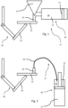
- Fig. 1 shows a first embodiment of a system for applying a tile adhesive for tiling a surface.
- a tile adhesive 10 is pumped by a piston 11 in a cylinder 12 of a pumping unit 30 of an adhesive supplying device 27.
- the cylinder 12 may be refilled by a funnel 13.
- a robot arm 14 of an automated supporting and moving device (robot) 28 supports and moves a tile 15.
- the tile adhesive 10 is supplied via a nozzle 16 onto the tile.
- the robot arm 14 of the robot moves the tile 15 so that the tile adhesive is distributed on the tile 15 (in this case, the nozzle 16 may not move).
- the robot arm 14 may position the tile 15 on the surface (ground and/or wall and/or panel) to be tiled.
- Fig. 2 shows a schematic illustration of a second embodiment of the invention.
- the tile adhesive 10 is (directly) pumped from a barrel 17.
- the pumped tile adhesive 10 may be supplied via a supply line 18 to the nozzle 16.
- the solution of Fig. 2 reduces the cleaning effort and speeds up the process.
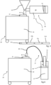
- a linear moving device 19 can be provided (apart therefrom, the embodiment of Fig. 3 may be identical to the embodiment of Fig. 1 and the embodiment of Fig. 4 may be identical to the embodiment of Fig. 2 ).
- the linear moving device 19 may be configured to move the tile 15 in at least three (up to six) different axes.
- the linear moving device 19 is configured to move the tiles 15 to the surface to be tiled (e.g. ground and/or wall and/or panel) which is indicated in Fig. 3 by tiles 15a, 15b, 15c and 15d.
- tiles 15a to 15d may be part of a tiling of the ground. Further tiles (not shown in Fig. 3 ) may be arranged along a direction perpendicular to the plane of the drawing (e.g. in a square or hexahedral pattern.
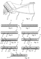
- Fig. 5 shows an embodiment of the nozzle 16.
- the nozzle 16 comprises a plurality of apertures 20.
- the apertures 20 of Fig. 5 are arranged in (one) row (in a one-dimensional arrangement). Via a fastening structure 21 (thread), the nozzle 16 can be fastened to a supply means (not shown in Fig. 5 ).
- the apertures 20 may be formed by an end piece 22 which can be connected to a main body 23 of the nozzle 16. This means, main body 23 and end piece 22 may form two different pieces (which are connectable with each other).
- Fig. 6 shows another embodiment of the nozzle 16 in a front view.
- the embodiment of Fig. 6 is similar to the embodiment of Fig. 5 and comprises several (e.g. ten) apertures 20.
- Fig. 7 showing another embodiment of the nozzle 16, the dimension of the apertures 20 can be different (in this case, in comparison with Fig. 6 , smaller).
- Fig. 8 shows an embodiment of the nozzle 16 with (only) one aperture 20 formed by a slit.
- Fig. 9 shows another embodiment of the nozzle 16 comprising again a plurality of apertures with a different shape (in comparison with Fig. 6 and 7 ).
- Fig. 10 shows an embodiment of the nozzle 16, where the apertures 20 are interconnected by connection apertures 24 (which are smaller or thinner, respectively, or narrower, with respect to the apertures 20).
- Fig. 11 shows that the apertures 20 can be of a different number (in this case seven apertures).
- the geometry of the apertures 20 is similar to Fig. 10 (at least approximately semi-circles) and connection apertures 24 are provided.
- Figs. 12 and 13 again show an embodiment of the nozzle with different (reduced) number of apertures 20 (in the case of Fig. 12 , four; in the case of Fig. 13 , three).
- Fig. 14 shows an embodiment similar to Figs. 6 and 7 . However, in contrast to Figs. 6 and 7 , the number of apertures 20 is different and connection apertures 24 are provided connecting the apertures 20.
- connection apertures 24 may also be described as comprising a slit portion 25 (see for example, Fig. 13 ) with recesses 26 (forming the apertures 20).
- the length of the row of apertures 20 and/or the length of the (only) aperture 20 provided may be twice, preferably three times, further preferably five times, even further preferably eight times as large as the width of the aperture 20 or one of the apertures 20 (in Fig. 6 the width is indicated by arrow 27).
- the nozzle 16 may comprise several rows of apertures 20 (for example, at least a second or at least a third row which may be arranged in the width direction according to arrow 27 of Fig. 6 , e.g. in a square pattern or hexahedral pattern).
- the tile adhesive is pumped, extruded through the nozzle 16 and (directly) applied on a surface of a tile 15.
- the robot (comprising a robot arm 14 according to Fig. 1 or the moving device 19 of Fig. 2 or 4 ) preferably moves the tile 15 in two dimensions to allow an even application of the adhesive on the (full) surface of the tile.
- the nozzle 16 may be 3D printed to allow a complex shape.
- a (linear moving) piston is combined with a one-dimensional-configured nozzle for the application of the adhesive on the tile 15.
- a double application, on the surface to be tiled (e.g. floor and/or wall and/or panel) and on the tile may be performed.
- either one or two (different) pumps may be used to optimise the application time and the set-up.
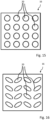
- a two-dimensional-configured nozzle permits optionally a faster application of the adhesive on the tiles.
- Examples for two-dimensional-configured nozzles are shown in figures 15 and 16.
- Fig. 15 shows a square lattice (in four rows and fours columns) of cylindrical apertures 20.
- Fig. 15 shows a square lattice (in four rows and fours columns) of elliptical apertures 20.
- the main axis of the elliptical structures are preferably inclined with respect to a direction defined by each respective row and/or inclined with respect to a direction defined by each respective column. Such inclined angle may be between 20 ° and 70 °.
- the elliptical structures may be oriented in different (in particular mirroring) directions.
- the two-dimensional-configured design of the nozzle may accelerate the application as the adhesive could be directly applied on the tile with less (or even no, in particular if the nozzle is, at least approximately, of the size of the tile) displacement of a robot.
Landscapes
- Engineering & Computer Science (AREA)
- Architecture (AREA)
- Civil Engineering (AREA)
- Structural Engineering (AREA)
- Robotics (AREA)
- Mechanical Engineering (AREA)
- Coating Apparatus (AREA)
- Application Of Or Painting With Fluid Materials (AREA)
- Finishing Walls (AREA)
Claims (13)
- Système destiné à carreler une surface, en particulier d'un mur ou du sol ou d'un panneau, comprenant un système destiné à appliquer de la colle à carrelage (10), comprenant :un dispositif de fourniture de colle (27) pour déposer la colle à carrelage (10) sur une surface d'un carreau (15), comprenant une buse (16) pour faire sortir la colle à carrelage (10) et une unité de pompage (30) pour pomper la colle à carrelage (10) dans la direction de la buse (16) ; etun dispositif de support et déplacement automatique (28), en particulier un robot, pour supporter et positionner le carreau (15) par rapport à la buse (16) de telle sorte que la colle à carrelage (10) puisse être répartie sur la surface du carreau (15) lorsqu'elle sort de la buse (16), caractérisé en ce quela buse (16) comprend un dispositif de mélange actif ou passif pour ajouter un composant durcisseur à la colle,dans lequel le dispositif de support et déplacement automatique (28), en particulier le robot, est également conçu pour positionner le carreau sur la surface à carreler.
- Système selon la revendication 1, caractérisé en ce que la buse (16) comprend une fente longitudinale (25) et/ou plusieurs ouvertures (20), de préférence disposées dans au moins une ou exactement une rangée, dans lequel les ouvertures (20) sont éventuellement connectées les unes aux autres ou déconnectées les unes des autres.
- Système selon une des revendications 1 et 2, caractérisé en ce que l'unité de pompage (30) comprend une pompe électrique et/ou hydraulique.
- Système selon une des revendications précédentes, caractérisé en ce que la buse (16) comprend un dispositif de chauffage.
- Système selon une des revendications précédentes, caractérisé en ce que le robot comprend un bras robotisé (14) et/ou un dispositif de support comprenant un système mobile linéaire (19) qui est mobile dans au moins deux, de préférence au moins trois, éventuellement jusqu'à six, directions axiales différentes.
- Système selon une des revendications précédentes, caractérisé par au moins un réservoir, en particulier rechargeable, de préférence une cartouche et/ou une bonbonne et/ou un fût (17), dans lequel le réservoir fait de préférence partie de l'unité de pompage.
- Système selon une des revendications précédentes, caractérisé par au moins un entonnoir (13) destiné à recevoir la colle.
- Système selon une des revendications précédentes, caractérisé par un, en particulier un deuxième, dispositif de fourniture de colle conçu pour déposer de la colle à carrelage (10) sur une surface à carreler.
- Procédé d'application de colle à carrelage (10), utilisant le système d'une des revendications précédentes, comprenant :la sortie de la colle à carrelage (10) d'une buse (16), un carreau (15) étant supporté et déplacé par rapport à la buse (16) par un système de support et déplacement automatique (28), en particulier un robot, de telle sorte que la colle à carrelage (10) soit répartie sur une surface du carreau (15),l'utilisation des deux composants d'une colle bicomposant et/ou l'ajout d'un composant durcisseur à la colle, en particulier par une opération de mélange actif ou passif, et/ou le versement de colle dans un entonnoir (13) pour remplir un réservoir.
- Procédé selon la revendication 9, caractérisé par le dépôt de la colle à carrelage (10) sur une surface à carreler.
- Procédé selon une des revendications 9 et 10 précédentes, caractérisé en ce que le carreau (15) est déplacé quand la colle à carrelage (10) sort de la buse (16).
- Procédé selon une des revendications 9 et 10 précédentes, caractérisé en ce que le carreau n'est pas déplacé par rapport à la buse (16) quand la colle à carrelage sort de la buse.
- Procédé destiné à carreler une surface, comprenant le procédé d'une des revendications 9 à 12 précédentes, et le positionnement d'une pluralité de carreaux (15) sur la surface à carreler.
Applications Claiming Priority (2)
| Application Number | Priority Date | Filing Date | Title |
|---|---|---|---|
| EP16202750 | 2016-12-07 | ||
| PCT/EP2017/081573 WO2018104334A1 (fr) | 2016-12-07 | 2017-12-05 | Système et procédé d'application d'une colle à carrelage |
Publications (3)
| Publication Number | Publication Date |
|---|---|
| EP3551818A1 EP3551818A1 (fr) | 2019-10-16 |
| EP3551818C0 EP3551818C0 (fr) | 2025-02-26 |
| EP3551818B1 true EP3551818B1 (fr) | 2025-02-26 |
Family
ID=57542771
Family Applications (1)
| Application Number | Title | Priority Date | Filing Date |
|---|---|---|---|
| EP17826448.7A Active EP3551818B1 (fr) | 2016-12-07 | 2017-12-05 | Système pour carreler et méthode utilisant ce système |
Country Status (6)
| Country | Link |
|---|---|
| US (1) | US10947743B2 (fr) |
| EP (1) | EP3551818B1 (fr) |
| CN (1) | CN109891036B (fr) |
| CO (1) | CO2019007163A2 (fr) |
| ES (1) | ES3019565T3 (fr) |
| WO (1) | WO2018104334A1 (fr) |
Families Citing this family (12)
| Publication number | Priority date | Publication date | Assignee | Title |
|---|---|---|---|---|
| IL264779A (en) * | 2019-02-11 | 2020-08-31 | Meir Turgeman Eliyahu | Cement dispenser |
| CN110242030B (zh) * | 2019-07-25 | 2021-10-22 | 广东博智林机器人有限公司 | 地砖铺设机器人及地砖铺设方法 |
| CN110593528A (zh) * | 2019-08-20 | 2019-12-20 | 广东博智林机器人有限公司 | 涂抹装置和具有其的铺贴设备 |
| CN110549324B (zh) * | 2019-09-19 | 2024-10-11 | 刘邵宏 | 一种马赛克图像铺贴机器人 |
| WO2021240230A1 (fr) * | 2019-11-05 | 2021-12-02 | Shmuel Levy | Système de revêtement de sol robotisé et intérieur industriel |
| CN111112013B (zh) * | 2019-12-31 | 2021-07-06 | 成都正大恒业机电设备有限公司 | 一种自动制砖系统 |
| CN111946033B (zh) * | 2020-08-18 | 2021-08-20 | 长春鸿源建设有限公司 | 一种建筑装修用手扶式地砖美缝剂填充装置 |
| USD977930S1 (en) * | 2021-05-12 | 2023-02-14 | Douglas S. Dreisbach | Tile filler troweling device |
| DE102022127333A1 (de) * | 2022-10-18 | 2024-04-18 | Baustoffwerke Gebhart & Söhne GmbH & Co. KG | Verfahren und Vorrichtung zur Herstellung eines Verbundkörpers |
| IL302799B1 (en) | 2023-05-09 | 2025-11-01 | Robee Contech Ltd | An automatic system for tiliing a surface |
| US20250237212A1 (en) * | 2024-01-22 | 2025-07-24 | Richard Hardman | Hydraulic Pump Providing Enhanced Physical Mobility |
| WO2026025115A1 (fr) * | 2024-07-26 | 2026-01-29 | Babcock Britt | Ensembles de pose d'adhésif d'agrégat et procédés de pose d'adhésif sur un agrégat |
Citations (1)
| Publication number | Priority date | Publication date | Assignee | Title |
|---|---|---|---|---|
| JP2004057995A (ja) * | 2002-07-31 | 2004-02-26 | Flex Giken:Kk | L字型タイル形成用接着剤塗布装置 |
Family Cites Families (23)
| Publication number | Priority date | Publication date | Assignee | Title |
|---|---|---|---|---|
| US2893026A (en) * | 1953-06-01 | 1959-07-07 | United Shoe Machinery Corp | Methods of bonding by thermoplastic adhesives |
| DE1015401B (de) * | 1955-06-10 | 1957-09-12 | Wilhelm Bienhuels | Schacht- und Streckenausbau |
| JP2775355B2 (ja) | 1991-03-29 | 1998-07-16 | 株式会社フジタ | 建築用床タイル材貼設装置 |
| US5749498A (en) * | 1996-07-03 | 1998-05-12 | Lavoie; Pierre | Applicator and spreader tool for adhesives |
| NO315030B1 (no) * | 1998-05-06 | 2003-06-30 | Dagfinn Andersen | Limpåföringsmaskin |
| US7153454B2 (en) * | 2003-01-21 | 2006-12-26 | University Of Southern California | Multi-nozzle assembly for extrusion of wall |
| BE1015401A3 (nl) * | 2003-03-05 | 2005-03-01 | Daglau N V | Inrichting voor het aanbrengen van fixatiemiddel voor het creeren van een vloer-, wand-of plafondbekleding. |
| GB0312974D0 (en) * | 2003-06-06 | 2003-07-09 | Spencer Alan | Dispensing apparatus and a dispensing nozzle for use therewith |
| EP1598502A3 (fr) | 2004-01-08 | 2007-05-30 | D'Hondt, Albert | Machine à enduire les dalles pour revêtement du sol |
| EP1711328B1 (fr) | 2004-01-20 | 2013-03-13 | University of Southern California | Systeme robotique pour la construction automatisee |
| US8177451B2 (en) * | 2004-01-23 | 2012-05-15 | Joon Park | Adhesive dispenser |
| US7485191B2 (en) * | 2004-05-21 | 2009-02-03 | Industrial Technology Research Institute | Nozzle tip and methods of use |
| US20060175432A1 (en) * | 2005-01-21 | 2006-08-10 | Reuben Brock | Apparatus and method for applying controlled patterns of liquid |
| DE202006016922U1 (de) * | 2006-11-02 | 2007-03-01 | Gerster, Karlheinz | Vorrichtung zum Aufbringen eines Haftmaterials auf eine Fliese oder fliesenähnliche Platte |
| US8985402B2 (en) * | 2009-03-17 | 2015-03-24 | Mark C. Schneider | Cove base nozzle for dispensing applications |
| KR20110009021U (ko) * | 2010-03-16 | 2011-09-22 | 우성도 | 타일 작업용 모르타르 공급기 |
| WO2012011004A1 (fr) * | 2010-07-02 | 2012-01-26 | Udviklingsselskabet Af 2002 Aps | Appareil permettant d'étendre un matériau adhésif |
| EP2888057A4 (fr) * | 2012-08-24 | 2016-07-13 | Adco Products Inc | Appareil de distribution d'adhésif de toiture |
| EP2907938A1 (fr) | 2014-02-18 | 2015-08-19 | IR-Eng.Limited | Appareil et procédé pour placer un carreau sur un plancher |
| CN104654297B (zh) * | 2014-12-24 | 2017-04-05 | 二重集团(德阳)重型装备股份有限公司 | 火焰加热喷头 |
| CN204955425U (zh) * | 2015-07-29 | 2016-01-13 | 武汉奥尔克特科技有限公司 | 一种用于彩色3d打印机的打印喷头 |
| US10697188B2 (en) * | 2017-03-31 | 2020-06-30 | Canvas Construction, Inc. | Automated drywalling system and method |
| CA3001811C (fr) * | 2018-04-17 | 2019-01-08 | Sergei Humann | Appareil d'application d'adhesif destine a des carreaux |
-
2017
- 2017-12-05 EP EP17826448.7A patent/EP3551818B1/fr active Active
- 2017-12-05 WO PCT/EP2017/081573 patent/WO2018104334A1/fr not_active Ceased
- 2017-12-05 CN CN201780065410.6A patent/CN109891036B/zh active Active
- 2017-12-05 ES ES17826448T patent/ES3019565T3/es active Active
- 2017-12-05 US US16/343,200 patent/US10947743B2/en active Active
-
2019
- 2019-07-03 CO CONC2019/0007163A patent/CO2019007163A2/es unknown
Patent Citations (1)
| Publication number | Priority date | Publication date | Assignee | Title |
|---|---|---|---|---|
| JP2004057995A (ja) * | 2002-07-31 | 2004-02-26 | Flex Giken:Kk | L字型タイル形成用接着剤塗布装置 |
Also Published As
| Publication number | Publication date |
|---|---|
| CN109891036B (zh) | 2022-08-09 |
| EP3551818A1 (fr) | 2019-10-16 |
| US20190242142A1 (en) | 2019-08-08 |
| ES3019565T3 (en) | 2025-05-20 |
| WO2018104334A1 (fr) | 2018-06-14 |
| US10947743B2 (en) | 2021-03-16 |
| CN109891036A (zh) | 2019-06-14 |
| CO2019007163A2 (es) | 2019-07-31 |
| EP3551818C0 (fr) | 2025-02-26 |
Similar Documents
| Publication | Publication Date | Title |
|---|---|---|
| EP3551818B1 (fr) | Système pour carreler et méthode utilisant ce système | |
| JP6538649B2 (ja) | 塗布装置および塗布方法 | |
| US20050194401A1 (en) | Automated plumbing, wiring, and reinforcement | |
| JP6538465B2 (ja) | 固体粒子を含有する液体材料の吐出装置および塗布装置並びに塗布方法 | |
| KR20160033165A (ko) | 다중 지점 시일 윤활 시스템 | |
| TWI665021B (zh) | 液體材料塗佈裝置及液體材料塗佈方法 | |
| DE60133478T2 (de) | Verfahren und vorrichtung zur versorgung von spritzeinrichtungen und spritzanlage mit einer solchen vorrichtung | |
| KR102195323B1 (ko) | 분무 시스템 압력 및 비율 제어 | |
| DE112016000374T5 (de) | Flüssigmaterialabgabevorrichtung | |
| CN106943906B (zh) | 用于混合的装置和方法 | |
| JP2021045906A (ja) | 立体造形システム | |
| JP2007524506A (ja) | 非接触式分与方法を使用してコンフォーマルコーティングする方法 | |
| CN106687223A (zh) | 用于分配器的阀座 | |
| KR101476338B1 (ko) | 다 자유도를 가진 고효율 자동화 도장 장치 | |
| KR101075176B1 (ko) | 구리스 자동 도포장치 | |
| EP3400126B1 (fr) | Article de distribution de poudre | |
| US11407176B2 (en) | Pumping system and method for 3D printing | |
| JP7402005B2 (ja) | 塗装方法 | |
| KR101790471B1 (ko) | 도포장치 및 이를 이용한 도포방법 | |
| KR20180109648A (ko) | 도포장치 및 이를 이용한 도포방법 | |
| TWM502059U (zh) | 垂直式自動補牆機器載具 | |
| KR20210143828A (ko) | 압출기 장치, 압출기 시스템 및 압출기 장치 및/또는 압출기 시스템의 용도 | |
| RU2787950C1 (ru) | Аппарат для 3d-печати и способ 3d-печати | |
| JPH02128063A (ja) | 自動タイル貼り付け装置 | |
| HK40040723A (en) | Coating system and coating method using the coating system |
Legal Events
| Date | Code | Title | Description |
|---|---|---|---|
| STAA | Information on the status of an ep patent application or granted ep patent |
Free format text: STATUS: UNKNOWN |
|
| STAA | Information on the status of an ep patent application or granted ep patent |
Free format text: STATUS: THE INTERNATIONAL PUBLICATION HAS BEEN MADE |
|
| PUAI | Public reference made under article 153(3) epc to a published international application that has entered the european phase |
Free format text: ORIGINAL CODE: 0009012 |
|
| STAA | Information on the status of an ep patent application or granted ep patent |
Free format text: STATUS: REQUEST FOR EXAMINATION WAS MADE |
|
| 17P | Request for examination filed |
Effective date: 20190708 |
|
| AK | Designated contracting states |
Kind code of ref document: A1 Designated state(s): AL AT BE BG CH CY CZ DE DK EE ES FI FR GB GR HR HU IE IS IT LI LT LU LV MC MK MT NL NO PL PT RO RS SE SI SK SM TR |
|
| AX | Request for extension of the european patent |
Extension state: BA ME |
|
| DAV | Request for validation of the european patent (deleted) | ||
| DAX | Request for extension of the european patent (deleted) | ||
| STAA | Information on the status of an ep patent application or granted ep patent |
Free format text: STATUS: EXAMINATION IS IN PROGRESS |
|
| 17Q | First examination report despatched |
Effective date: 20210611 |
|
| GRAP | Despatch of communication of intention to grant a patent |
Free format text: ORIGINAL CODE: EPIDOSNIGR1 |
|
| STAA | Information on the status of an ep patent application or granted ep patent |
Free format text: STATUS: GRANT OF PATENT IS INTENDED |
|
| INTG | Intention to grant announced |
Effective date: 20241004 |
|
| GRAS | Grant fee paid |
Free format text: ORIGINAL CODE: EPIDOSNIGR3 |
|
| GRAA | (expected) grant |
Free format text: ORIGINAL CODE: 0009210 |
|
| STAA | Information on the status of an ep patent application or granted ep patent |
Free format text: STATUS: THE PATENT HAS BEEN GRANTED |
|
| AK | Designated contracting states |
Kind code of ref document: B1 Designated state(s): AL AT BE BG CH CY CZ DE DK EE ES FI FR GB GR HR HU IE IS IT LI LT LU LV MC MK MT NL NO PL PT RO RS SE SI SK SM TR |
|
| REG | Reference to a national code |
Ref country code: GB Ref legal event code: FG4D |
|
| REG | Reference to a national code |
Ref country code: CH Ref legal event code: EP |
|
| REG | Reference to a national code |
Ref country code: DE Ref legal event code: R096 Ref document number: 602017088032 Country of ref document: DE |
|
| REG | Reference to a national code |
Ref country code: IE Ref legal event code: FG4D |
|
| U01 | Request for unitary effect filed |
Effective date: 20250324 |
|
| U07 | Unitary effect registered |
Designated state(s): AT BE BG DE DK EE FI FR IT LT LU LV MT NL PT RO SE SI Effective date: 20250328 |
|
| REG | Reference to a national code |
Ref country code: ES Ref legal event code: FG2A Ref document number: 3019565 Country of ref document: ES Kind code of ref document: T3 Effective date: 20250520 |
|
| PG25 | Lapsed in a contracting state [announced via postgrant information from national office to epo] |
Ref country code: RS Free format text: LAPSE BECAUSE OF FAILURE TO SUBMIT A TRANSLATION OF THE DESCRIPTION OR TO PAY THE FEE WITHIN THE PRESCRIBED TIME-LIMIT Effective date: 20250526 |
|
| PG25 | Lapsed in a contracting state [announced via postgrant information from national office to epo] |
Ref country code: PL Free format text: LAPSE BECAUSE OF FAILURE TO SUBMIT A TRANSLATION OF THE DESCRIPTION OR TO PAY THE FEE WITHIN THE PRESCRIBED TIME-LIMIT Effective date: 20250226 |
|
| PG25 | Lapsed in a contracting state [announced via postgrant information from national office to epo] |
Ref country code: NO Free format text: LAPSE BECAUSE OF FAILURE TO SUBMIT A TRANSLATION OF THE DESCRIPTION OR TO PAY THE FEE WITHIN THE PRESCRIBED TIME-LIMIT Effective date: 20250526 Ref country code: IS Free format text: LAPSE BECAUSE OF FAILURE TO SUBMIT A TRANSLATION OF THE DESCRIPTION OR TO PAY THE FEE WITHIN THE PRESCRIBED TIME-LIMIT Effective date: 20250626 |
|
| PG25 | Lapsed in a contracting state [announced via postgrant information from national office to epo] |
Ref country code: HR Free format text: LAPSE BECAUSE OF FAILURE TO SUBMIT A TRANSLATION OF THE DESCRIPTION OR TO PAY THE FEE WITHIN THE PRESCRIBED TIME-LIMIT Effective date: 20250226 |
|
| PG25 | Lapsed in a contracting state [announced via postgrant information from national office to epo] |
Ref country code: GR Free format text: LAPSE BECAUSE OF FAILURE TO SUBMIT A TRANSLATION OF THE DESCRIPTION OR TO PAY THE FEE WITHIN THE PRESCRIBED TIME-LIMIT Effective date: 20250527 |
|
| PG25 | Lapsed in a contracting state [announced via postgrant information from national office to epo] |
Ref country code: SM Free format text: LAPSE BECAUSE OF FAILURE TO SUBMIT A TRANSLATION OF THE DESCRIPTION OR TO PAY THE FEE WITHIN THE PRESCRIBED TIME-LIMIT Effective date: 20250226 |
|
| PG25 | Lapsed in a contracting state [announced via postgrant information from national office to epo] |
Ref country code: CZ Free format text: LAPSE BECAUSE OF FAILURE TO SUBMIT A TRANSLATION OF THE DESCRIPTION OR TO PAY THE FEE WITHIN THE PRESCRIBED TIME-LIMIT Effective date: 20250226 |
|
| PG25 | Lapsed in a contracting state [announced via postgrant information from national office to epo] |
Ref country code: SK Free format text: LAPSE BECAUSE OF FAILURE TO SUBMIT A TRANSLATION OF THE DESCRIPTION OR TO PAY THE FEE WITHIN THE PRESCRIBED TIME-LIMIT Effective date: 20250226 |
|
| PLBE | No opposition filed within time limit |
Free format text: ORIGINAL CODE: 0009261 |
|
| STAA | Information on the status of an ep patent application or granted ep patent |
Free format text: STATUS: NO OPPOSITION FILED WITHIN TIME LIMIT |
|
| PGFP | Annual fee paid to national office [announced via postgrant information from national office to epo] |
Ref country code: TR Payment date: 20251127 Year of fee payment: 9 |
|
| 26N | No opposition filed |
Effective date: 20251127 |
|
| U20 | Renewal fee for the european patent with unitary effect paid |
Year of fee payment: 9 Effective date: 20260102 |