EP3551804B1 - Module for an artificial reef and method - Google Patents
Module for an artificial reef and method Download PDFInfo
- Publication number
- EP3551804B1 EP3551804B1 EP17818606.0A EP17818606A EP3551804B1 EP 3551804 B1 EP3551804 B1 EP 3551804B1 EP 17818606 A EP17818606 A EP 17818606A EP 3551804 B1 EP3551804 B1 EP 3551804B1
- Authority
- EP
- European Patent Office
- Prior art keywords
- module
- walls
- cavity
- artificial reef
- engagement
- Prior art date
- Legal status (The legal status is an assumption and is not a legal conclusion. Google has not performed a legal analysis and makes no representation as to the accuracy of the status listed.)
- Active
Links
Images


Classifications
-
- E—FIXED CONSTRUCTIONS
- E02—HYDRAULIC ENGINEERING; FOUNDATIONS; SOIL SHIFTING
- E02B—HYDRAULIC ENGINEERING
- E02B3/00—Engineering works in connection with control or use of streams, rivers, coasts, or other marine sites; Sealings or joints for engineering works in general
- E02B3/04—Structures or apparatus for, or methods of, protecting banks, coasts, or harbours
- E02B3/046—Artificial reefs
-
- A—HUMAN NECESSITIES
- A01—AGRICULTURE; FORESTRY; ANIMAL HUSBANDRY; HUNTING; TRAPPING; FISHING
- A01K—ANIMAL HUSBANDRY; AVICULTURE; APICULTURE; PISCICULTURE; FISHING; REARING OR BREEDING ANIMALS, NOT OTHERWISE PROVIDED FOR; NEW BREEDS OF ANIMALS
- A01K61/00—Culture of aquatic animals
- A01K61/70—Artificial fishing banks or reefs
- A01K61/73—Artificial fishing banks or reefs assembled of components
-
- A—HUMAN NECESSITIES
- A01—AGRICULTURE; FORESTRY; ANIMAL HUSBANDRY; HUNTING; TRAPPING; FISHING
- A01K—ANIMAL HUSBANDRY; AVICULTURE; APICULTURE; PISCICULTURE; FISHING; REARING OR BREEDING ANIMALS, NOT OTHERWISE PROVIDED FOR; NEW BREEDS OF ANIMALS
- A01K61/00—Culture of aquatic animals
- A01K61/70—Artificial fishing banks or reefs
- A01K61/77—Artificial fishing banks or reefs of monolithic form, e.g. blocks
-
- E—FIXED CONSTRUCTIONS
- E02—HYDRAULIC ENGINEERING; FOUNDATIONS; SOIL SHIFTING
- E02B—HYDRAULIC ENGINEERING
- E02B3/00—Engineering works in connection with control or use of streams, rivers, coasts, or other marine sites; Sealings or joints for engineering works in general
- E02B3/04—Structures or apparatus for, or methods of, protecting banks, coasts, or harbours
- E02B3/06—Moles; Piers; Quays; Quay walls; Groynes; Breakwaters ; Wave dissipating walls; Quay equipment
-
- E—FIXED CONSTRUCTIONS
- E02—HYDRAULIC ENGINEERING; FOUNDATIONS; SOIL SHIFTING
- E02B—HYDRAULIC ENGINEERING
- E02B3/00—Engineering works in connection with control or use of streams, rivers, coasts, or other marine sites; Sealings or joints for engineering works in general
- E02B3/04—Structures or apparatus for, or methods of, protecting banks, coasts, or harbours
- E02B3/12—Revetment of banks, dams, watercourses, or the like, e.g. the sea-floor
- E02B3/129—Polyhedrons, tetrapods or similar bodies, whether or not threaded on strings
-
- E—FIXED CONSTRUCTIONS
- E02—HYDRAULIC ENGINEERING; FOUNDATIONS; SOIL SHIFTING
- E02B—HYDRAULIC ENGINEERING
- E02B3/00—Engineering works in connection with control or use of streams, rivers, coasts, or other marine sites; Sealings or joints for engineering works in general
- E02B3/04—Structures or apparatus for, or methods of, protecting banks, coasts, or harbours
- E02B3/12—Revetment of banks, dams, watercourses, or the like, e.g. the sea-floor
- E02B3/14—Preformed blocks or slabs for forming essentially continuous surfaces; Arrangements thereof
-
- B—PERFORMING OPERATIONS; TRANSPORTING
- B28—WORKING CEMENT, CLAY, OR STONE
- B28B—SHAPING CLAY OR OTHER CERAMIC COMPOSITIONS; SHAPING SLAG; SHAPING MIXTURES CONTAINING CEMENTITIOUS MATERIAL, e.g. PLASTER
- B28B7/00—Moulds; Cores; Mandrels
- B28B7/16—Moulds for making shaped articles with cavities or holes open to the surface, e.g. with blind holes
- B28B7/18—Moulds for making shaped articles with cavities or holes open to the surface, e.g. with blind holes the holes passing completely through the article
- B28B7/183—Moulds for making shaped articles with cavities or holes open to the surface, e.g. with blind holes the holes passing completely through the article for building blocks or similar block-shaped objects
-
- B—PERFORMING OPERATIONS; TRANSPORTING
- B28—WORKING CEMENT, CLAY, OR STONE
- B28B—SHAPING CLAY OR OTHER CERAMIC COMPOSITIONS; SHAPING SLAG; SHAPING MIXTURES CONTAINING CEMENTITIOUS MATERIAL, e.g. PLASTER
- B28B7/00—Moulds; Cores; Mandrels
- B28B7/28—Cores; Mandrels
- B28B7/30—Cores; Mandrels adjustable, collapsible, or expanding
- B28B7/32—Cores; Mandrels adjustable, collapsible, or expanding inflatable
-
- Y—GENERAL TAGGING OF NEW TECHNOLOGICAL DEVELOPMENTS; GENERAL TAGGING OF CROSS-SECTIONAL TECHNOLOGIES SPANNING OVER SEVERAL SECTIONS OF THE IPC; TECHNICAL SUBJECTS COVERED BY FORMER USPC CROSS-REFERENCE ART COLLECTIONS [XRACs] AND DIGESTS
- Y02—TECHNOLOGIES OR APPLICATIONS FOR MITIGATION OR ADAPTATION AGAINST CLIMATE CHANGE
- Y02A—TECHNOLOGIES FOR ADAPTATION TO CLIMATE CHANGE
- Y02A10/00—TECHNOLOGIES FOR ADAPTATION TO CLIMATE CHANGE at coastal zones; at river basins
- Y02A10/26—Artificial reefs or seaweed; Restoration or protection of coral reefs
-
- Y—GENERAL TAGGING OF NEW TECHNOLOGICAL DEVELOPMENTS; GENERAL TAGGING OF CROSS-SECTIONAL TECHNOLOGIES SPANNING OVER SEVERAL SECTIONS OF THE IPC; TECHNICAL SUBJECTS COVERED BY FORMER USPC CROSS-REFERENCE ART COLLECTIONS [XRACs] AND DIGESTS
- Y02—TECHNOLOGIES OR APPLICATIONS FOR MITIGATION OR ADAPTATION AGAINST CLIMATE CHANGE
- Y02A—TECHNOLOGIES FOR ADAPTATION TO CLIMATE CHANGE
- Y02A40/00—Adaptation technologies in agriculture, forestry, livestock or agroalimentary production
- Y02A40/80—Adaptation technologies in agriculture, forestry, livestock or agroalimentary production in fisheries management
- Y02A40/81—Aquaculture, e.g. of fish
Definitions
- the present invention relates to the field of underwater structures, for example artificial reefs, anti-seabed scouring and anti-trawling structures. More particularly, but not exclusively, one or more embodiments relate to stackable and or inter-engageable interlocking blocks which can be positioned underwater to provide strong and or substantially immoveable structures with the ability to allow and encourage marine life inhabitation.
- Sea bed scouring is caused by changes in the flow pattern of the water around the base of a monopile.
- the most common technique to counteract scouring is to dump rock and other such material, typically up to 200,000 tonnes, around the base of the support monopile.
- Some examples include the sinking of retired ships, bundles of car tyres, concrete breeze blocks and so on.
- EP1036638A1 discloses a concrete block having comparatively light weight and capable of being manufactured easily and used in various fields of application.
- US6431792B1 discloses an artificial reef structure including various building components that are preformed from concrete and the like.
- WO9913176A1 discloses a masonry wall system incorporating a plurality of courses of masonry blocks, each block consisting of interlocking dovetails along with vertical and horizontal mating surfaces.
- JPH115205A discloses a steric frame-like mould for concrete elements comprising four longitudinal frame forming parts disposed at an interval from each other, and eight lateral frame forming parts laterally installed between opposed upper ends and between lower ands of the respective parts in a steric frame state having therein substantially spherical shape hollow parts and circular shape side central part holes provided at a center of an outside face.
- JPH10136829 discloses a fish bank block to mimic rocks having a plurality of through-holes.
- JP2001355220 discloses a block which comprises a hollow shell wall 3 having a spherical outer surface and inner surface, and the whole body of the shell wall 3 is integrally moulded of concrete, and a number of wall ports 5 is formed in the shell wall 3.
- the present invention provides a module for an underwater structure according to claim 1.
- the module comprises a plurality of walls defining a cavity configured such that at least two walls of said plurality of walls confront one another to provide respective stack support surfaces for supporting a said module, said walls are substantially parallel to form complementary stack surfaces, such that one stack surface may rest on a surface and the other complementary stack surface provides a rest surface for another module.
- Two or more walls of said plurality of walls each comprise an aperture providing a conduit through each two or more walls to said cavity, respective apertures of said two or more walls and said cavity configured to provide a water flow path into, through and from said cavity.
- the water flow path may be considered unconstrained or at least substantially unconstrained in that water may flow through the apertures and cavity without deviation or interruption other than by the module or cavity walls.
- an aperture may be occluded or partially occluded but still the module when on its own may provide water pathways which may be considered unconstrained or substantially unconstrained.
- the central spherical cavity defined by the plurality of walls of said module substantially provides protection for, and encourages, growth of marine life such as fish, corals, barnacles, shellfish, sea-weed and other flora and fauna. Ingress of water through said apertures in said walls may encourage or promote diffusion of local sea currents through and out of said module.
- By permitting water flow through the module the formation of "scouring currents" around the module, or a collection of modules, is discouraged compared to an arrangement that blocks water flow. This will significantly reduce local sea-bed scouring around monopile supports for wind turbines and the module itself.
- the module is particularly suitable as an artificial reef block and for use in combining with other such blocks to form an artificial reef.
- substantially parallel stack support surfaces of said module enables said module to be stacked one on top of each other, forming an artificial reef structure.
- substantially parallel stack supports relate to two opposing surfaces on the top and bottom of said module arranged to allow efficient stacking of more than one said module.
- any suitable settable material may be used to form a said module provided it is sufficiently viscous to substantially fill the mould and is not soluble in water when set.
- said walls comprise a masonry material, for example a wall may comprise concrete.
- Masonry material is relatively heavy and may comprise various brick, rock or other material found in masonry, including metal rods and mesh typically bound together with concrete.
- said module comprises one or more apertures that are configured so that the module walls have sufficient mechanical strength to support at least one said module and the apertures allow substantial ingress of water to a cavity within said module, for example said cavity may comprise curved walls configured to provide a support arch for one or more of said plurality of walls. Said cavity may act as a shelter for marine life such as shells, crustaceans, fish, and other flora and fauna.
- said cavity comprises curved walls configured to provide a vault-like support for one or more of said plurality of walls.
- the module may include a plurality of textured or smooth walls, wherein at least one of said plurality of walls comprises a rough outer surface to promote growth of certain species of marine life.
- the module further comprises an engagement formation on at least one of said plurality of walls configured to engage with a complementary formation disposed on an element external to said module, wherein said engagement formation is disposed on an outer wall of said one or more plurality of walls.
- Said engagement formation being disposed on at least two of said plurality of walls and wherein a first said engagement on a first of said at least two of said plurality of walls is complementary to a second said engagement formation on a second of said at least two or more plurality of walls.
- Said at least two of said plurality of walls oppose each other so as to provide respective stack surfaces.
- First and second engagement portions on said at least two of said plurality of walls are configured for engagement with a laterally disposed element external to said module.
- the engagement may be a vertically disposed element external to said module.
- an external element configured to engage with a module.
- Such an element may comprise a part of a larger structure such as a jetty or sea wall or the like.
- the external element may be another module or at least comprise another of the modules.
- a method of manufacturing a module for an artificial reef block comprising placing an object having the shape of a cavity to be formed in a module to be manufactured in a mould comprising an inner configuration corresponding to the outer configuration of said module; placing a first and second ring to extend from respective first and second inner walls to said object; filling said mould with a settable mixture comprising masonry material; and allowing said settable mixture to set and removing said module from said mould.
- the method further comprises removing said first and second ring prior to removing said module from said mould to allow removal of said object.
- Said object that forms said cavity is collapsible so as to aid removal of said object from said module with ease and may comprise an inflatable object that is deflatable so as to aid removal of said object from said module.
- the method may comprise removing some partially set mixture from an exterior or interior wall or part thereof to provide a rough surface so as to expose aggregate surfaces. This allows for a variety of surface textures for adhesion of many different marine life species which require a variety of said textures.
- a structure comprising a plurality of modules, wherein a first group of said plurality of modules support a second group of said plurality of modules, a stack surface of each of said second group of said plurality of modules resting on one or more stack surfaces of said first group of said plurality of modules.
- adjacent modules in a vertical direction are interlocked with each other via said engagement formation and complementary engagement formation.
- Said walls of said modules may be a plastic material to discourage growth of marine life and aid to removal of said module at the end of its life.
- Said plastic material may comprise a suitable thermoplastic such as Low Density Polyethylene (LDPE), High Density Polyethylene (HDPE), Polypropylene, Polyvinyl Chloride (PVC), Polyethylene Terephthalate (PET), recycled plastic, or other similar materials.
- LDPE Low Density Polyethylene
- HDPE High Density Polyethylene
- PVC Polyvinyl Chloride
- PET Polyethylene Terephthalate
- recycled plastic or other similar materials.
- the method of construction could be, but not be limited to, extrusion moulding, injection moulding, vacuum forming, stretch moulding, or blow-moulded.
- Fig. 1 is an illustrative schematic drawing of an artificial reef block 10 in accordance with an embodiment of the present invention.
- a reef block 10 may be utilised for the promotion of growth of marine wildlife, for example; coral; oysters; barnacles; seaweed and the like.
- Such a reef block 10 may also provide protection for various fish species during their early life development by way of the central spherical cavity 14 providing shelter.
- the configuration of the artificial reef block 10 is cuboid, and is generally but not exclusively, of a concrete mixture.
- One specific mix is made of stone, sand, cement, high-range plasticiser, micro silica and silica fibres.
- An illustrative ratio of the main constituents could be 3 parts stone or substrate, 2 parts sand, 1 part cement, 1 part micro silica. Additionally, 100ml of plasticiser (ADVA 650), and 10-20g of fibres are incorporated and mixed in to the above mix for a module of 1 m 3 . 100 ml corresponds to 0.0001 m 3 and therefore is not a significant ratio in terms of parts, and considered to be an additive to the main mix. There are a total of seven parts contributing to the 1 m 3 reef block, therefore one part corresponds to a volume of 1/7 m 3 .
- the additional fibres used are typically a high-performance, monofilament, polypropylene fibre developed as a crack controlling additive for cementitious materials. It is used to inhibit the formation of small cracks which can occur through plastic shrinkage, premature drying and early thermal changes, in order to provide utilisation of the intrinsic properties of the hardened cementitious material.
- the high-range plasticizer is a chemical admixture used for improving the workability of the mix; it is used as a dispersant to avoid particle aggregation; and used to improve flow characteristics.
- the mix is designed to have a relatively low PH of around 8.3 compared with conventional mixes of concrete, which typically has a PH level of 11-13. This will be more suitable for marine life adhesion.
- the micro silica and silica fibres aid in strengthening the artificial reef block 10 and give the mixture a predicted life in seawater of around 500 years.
- the micro silica and silica fibres also help to minimise the leaching out of any concrete toxins into the environment.
- Other heavy materials may be used.
- an aggregate is added to the mixture and the individual external faces may have a rough surface to promote the growth of barnacles, various algae and other flora and fauna. This may be achieved by gently washing off a small layer of concrete on the exterior of the cube exposing the aggregate before it is fully cured. This gives a range of surface textures which may appeal to a range of sea flora and fauna species.
- the internal and external surfaces may be relatively smooth, which also has its advantages for other species of marine life.
- the central cavity 14 is spherical having its centre aligned close to the centre of the surrounding edges of the block 10.
- the diameter of the cavity is smaller than the length of the smallest face of the block 10, such that it does not extend to the exterior of the block 10.
- the entrances 12 show the points at which fish and other sea creatures may enter. They allow a passage from the exterior to interior of the artificial reef block and are situated in the centre of all of the external faces.
- the central cavity 14 also allows water to flow freely through the artificial reef block 10.
- Two cross-sectional views labelled section AA and section BB are shown in fig. 2a and fig. 2b respectively.
- Figs. 2a and 2b show the two cross-sectional views across the lines labelled AA and BB respectively shown in fig. 1 for artificial reef block 10.
- the cross-sections show cylindrical spaces 13, central spherical cavity 14, side entrances 12, and side walls 16.
- Marine life can enter or exit the spherical centre cavity 14 of the artificial reef block 10 through any of the circular entrances 12.
- water may pass through relatively uninhibited, allowing a current to impinge upon the artificial reef blocks without hitting a completely solid surface; for this reason reef blocks 10 may also be used to reduce currents and therefore as a sea barrier.
- an artificial reef block 10 can be submerged underwater individually or as part of a cluster of two or more blocks.
- the spherical cavity 14 creates a uniform centre of arches that enable the reef blocks 10 to be weight bearing and so may be stacked to a relatively large number of layers, for example up to 10 layers.
- the spherical central cavity 14, with the entrances from the exterior to interior allows some water current to pass through the wall hence acting to reduce the force impinging upon it due to the current.
- One skilled in the art can conceive of various combinations of sizes and, shapes of artificial reef blocks to form a variety of structures.
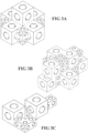
- Some illustrative structures are shown in figs. 3a, 3b, and 3c .
- Two sizes of the artificial reef block 10 are illustrated in various structures and arrangements forming conditions suitable for the promotion of marine life and flora and fauna.
- the cuboid structure allows the reef blocks 10 to be easily stacked, and the central cavity forms a plurality of central arches and columns for bearing the weight of the artificial reef blocks.
- the illustrative structures may create a large protected environment inside of the artificial reef blocks for marine life to thrive.
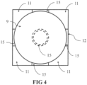
- the method of construction of an artificial reef block 10 in accordance with an embodiment of the present invention comprises placing a spherical inflatable bladder 9 inside a cuboid crate 5.
- the size of the spherical bladder 9 corresponds to the inside dimension of the central spherical cavity section ( fig. 1 , 14 ) required for the artificial reef block 10; and the inner dimensions of the cuboid crate 5 match that of the outer dimensions of the artificial reef block (1x1x1m) 10.
- Six edging rings 15 are used to position the spherical bladder in the centre of the cuboid crate 5.
- the thickness or length of respective edging rings 15 are greater than or equal to the difference between the diameter of the inside of the cuboid crate 5 and the spherical bladder 9.
- the width of each of the six edging rings will be greater than 0.1m.
- the larger the diameter of a ring, the greater its axial length 21 will need to be, because the distance between the outer of the spherical bladder 9 and inner of the cuboid crate 5 increases with ring diameter.
- the six edging rings form a join between the inside of the small cuboid crate 5 and the outer surface of the spherical bladder 9.
- the space 11 between the inner walls of the cuboid crate 5 and the outer surface of the spherical bladder 9 can be filled with a concrete mix.
- the six edging rings 15 are cylindrical in shape, with length 21 but are not limited to such a configuration.
- the rings are such that the walls 13 are conical, angled, convex or concave for example. They may also be other shapes, and not always a circular cross-section, such that they create a join between the six inner surfaces of the cuboid crate 5 and the outer surface of the spherical bladder 9.
- Respective edging rings 15 do not need to be the same size, diameter, or thickness so long as the continuous join between the six inner surfaces of the small cuboid crate 5 and the outer surface of the spherical bladder 9 is maintained. For example, one could have smaller rings on two of the faces and so on.
- the cuboid crate 5 may be constructed of wood, metal, plywood, fibreglass, plastic or any other similar material.
- One skilled in the art can easily envisage a crate 5 constructed of any or a combination of any of the aforesaid materials.
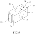
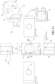
- FIG. 5 shows a schematic of a single artificial reef block 18 with male and female formations on respective faces of two of the exterior faces 20 and 22 respectively.
- the inter-engageable members on the ends of the reef block are such that one end of one artificial reef block can be engaged with the complementary end formation of another reef block to form an interlocked arrangement forming something akin to a single monolithic structure.
- the term "monolithic” is used herein to refer to a structure that substantially appears and acts as a single structure although comprised of smaller components, described here with interengagement formations, which may be interlocking formations. Two or more artificial reef blocks can be engaged in this way, allowing formation of as large a monolithic structure as required for the given application. This may include but not be limited to sea defences, large artificial reef structures, submerged breakwaters and anti-trawling devices for example.
- artificial reef block 18 has cylindrical spaces 13, spherical centre 14 with entrances 12.
- the number of entrances is reduced to four in this embodiment due to the male and female formations 20 and 22 at respective opposite walls.
- the male and female formations 20 and 22 respectively are at a position such that they are in the same plane and on exterior faces opposite one another.
- the male and female formations are in the form of a sliding dovetail like joint.
- the sliding dovetail joint provides the interlocking strength achieved by a conventional dovetail joint, but with the ability of some vertical movement.
- the male formation 20 slides into the female formation 22 and one may be engaged with the other by vertically offsetting two artificial reef blocks such that the bottom face of one artificial reef block 18, is opposite to top face of another artificial reef block; aligning rear faces 24 on one artificial reef block 18 to the front faces 26 of the second reef block 18; and then providing a vertical motion such that the top face of one artificial reef block 18 is in alignment with the second artificial reef block 18 and lowering one reef block 18 with respect to the other to engage respective male and female formations, hence interlocking the two artificial reef blocks 18 together.
- two or more artificial reef blocks may be interlocked together to form a long, substantially immoveable monolithic structure with high strength due to the interengaging formations.
- the described embodiment uses a sliding dovetail joint, one skilled in the art may envisage other joining mechanisms which offer similar strength and ability to for a monolithic structure.
- the artificial reef block 18 shown in fig. 5 is also capable of being stacked which will allow even larger structures to be formed with the added strength of the horizontal coupling of the sliding dovetail joints 40.
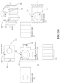
- Illustrative structures are shown in fig. 6 a) and 6 b).
- Figs. 6 a) and 6 b) show a plurality of interlocked artificial reef blocks 18 forming a large monolithic structure which, due to the central spherical cavities 14 and entrances 12, allows currents to flow through the barrier.
- the central spherical cavities 14 and entrances 12 act so as to reduce the local current and thereby reduce the scouring effect around subsea structures such as monopiles for wind turbines and the like.
- FIG. 6b also shows a method of stacking the artificial reef blocks 18.
- an artificial reef block 19 is shown to be moved in a downward direction to add to the large monolithic structure. Its male formation 20 is aligned with a female formation 22 on another artificial reef block such that when 19 is moved vertically downward, it interengages with another artificial reef block 18 forming a strong male-female interlocking joint 40.
- the bottom wall of the artificial reef block 19 is supported by the top walls of the artificial reef blocks it is placed on. This is the manner of the stack support provided to each subsequent layer of blocks.
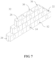
- FIG. 7 illustrates another variant of the artificial reef block and is similar to the embodiment shown in fig. 5 .
- An artificial reef block 28 includes entrances 12, cylindrical space 13, central spherical space 14, male formation 20, corresponding female formation 22 and vertical dowels 30. It is the vertical dowels 30 that distinguishes this particular embodiment to the one in fig. 6 (6a, and 6b ).
- the vertical dowels 30 have a corresponding female formation on the opposite face of the artificial reef block 28.
- the dowels are positioned on one face of the artificial reef block 28 with the corresponding female part disposed on the opposing face of a second artificial reef block.
- dowel 7 shows two vertical dowels 30, but in other embodiments not shown any suitable number may be used.
- the shape and form of the dowel and corresponding hole may be other than cylindrical as well.
- the dowels are cylindrical in shape but other shapes may be used, for example square or polygon cross-section dowels.
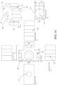
- Fig. 7 shows an example monolithic structure 32 which incorporates the dowels 30.
- the individual artificial reef blocks 28 are stacked such that each layer is offset by half the length of the artificial reef block. This is similar to a common running bond used in brick laying. In other embodiments one may use an arrangement that uses different patterns and types of offsets and embodiments of the present invention is are not limited to the current embodiment or embodiments discussed herein.
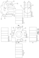
- Fig. 8a shows a different perspective of the monolithic structure 32 illustrated in Fig. 7 .
- Fig. 8 a) shows a plurality of interlocked artificial reef blocks 28 forming a large monolithic structure, which due to the central spherical cavities 14 and entrances 12, allow currents to flow through the barrier 32.
- the central spherical cavities 14 and entrances 12 will act so as to reduce the local current and thereby reduce the scouring effect around subsea structures such as the monopile of wind turbines and the like.
- Fig. 8 a) also shows the method of stacking the artificial reef blocks 28.
- an artificial reef block 29 is shown to be moved in a downward direction to add to the large monolithic structure.
- Fig. 8b shows a plan view of three interlocked artificial reef blocks 28 with the dowels in place.
- the male projection 20 is interlocked with a female projection 22 on another artificial reef block 28 to form the male-female interlocking joint 40.
- It also shows the relative position of the dowels 30 to the female holes 34 in this embodiment. They are diagonally opposite in the plane shown, so that when stacked they overlap by half the length of the artificial reef block 28.
- the vertical dowels When stacked, the vertical dowels act to add strength vertically between adjacent rows of artificial reef blocks. This inhibits movement of vertically adjacent rows with respect to each other due to water pressure from undersea currents and forces.
- an interlockable artificial reef block may be curved so that when a plurality of artificial reef blocks are coupled together they form a circular monolithic structure rather than a linear monolithic structure.
- An example is shown in fig. 9 a).
- Fig 9 a) shows a schematic plan view of a circular monolithic structure 36. In a particular embodiment it is in the form of a ring with an outer diameter of 12.732m, and thickness 1m. Structure 36 is comprised of twenty curved artificial reef blocks 38. Thus each artificial reef block fits inside of an 18 degree sector of the circle formed by the outer diameter.
- the individual curved artificial reef blocks have an outer radius of 6.366m 44, an inner radius of 5.366m 46, and both radii are concentric meaning they have a common centre 42.
- Each of the curved artificial reef blocks 38 have a spherical central space 14 and entrances 12. They are similar to the other embodiments of the current invention in that they have the male formation on one end, and the female formation on the opposing end to form of a sliding dovetail joint. Both can be brought into an interlocking arrangement 40 which will give the structure great strength from subsea currents and forces.
- the spherical cavities 14 and entrances 12 allow the currents to flow through and around the support monopile of a wind turbine, and therefore reduce the effect of seabed scouring that occurs.
- a 3D isometric projection of this embodiment is illustrated in fig. 9b .
- the illustrated embodiment is for a fixed radius structure, but can be changed to accommodate larger or smaller monopiles or other curved circular configurations.
- the material used for the construction of the artificial reef block may be comprised of a high-impact, durable plastic material so as to discourage the growth of marine life, while still acting to reduce the seabed scour around fixed structures.
- This will allow the artificial reef blocks to be removed easily when the structure is required to be removed.
- some wind farms have the requirement that all aspects of the wind turbines must be removed when their end of life is reached, which may include the wind turbine itself, support pole, any scouring protection and the like.
- the artificial reef blocks employed as scour protection will be required to be removed. With 25 years of marine life growth, this will be very difficult to achieve, and therefore a solution which inhibits marine life growth will need to be employed.
- thermoplastics such as Low Density Polyethylene (LDPE), High Density Polyethylene (HDPE), Polypropylene, Polyvinyl Chloride (PVC), Polyethylene Terephthalate (PET), recycled plastic, or other similar materials.
- the method of construction could be, but not be limited to, extrusion moulding, injection moulding, vacuum forming, stretch moulding, or blow-moulded.
- FIG. 10 shows an illustrative schematic and projection of a single interlockable reef block 50 in accordance with another embodiment of the present disclosure and is similar to that shown in Fig. 5 .
- Block 50 includes male and female formations on respective faces of two of the exterior faces 20 and 22 respectively.
- the inter-engagable members on the exterior of the reef block are such that one end of one artificial reef block can be engaged with the complementary end formation of another reef block to form an interlocked arrangement forming something akin to a single monolithic structure.
- Engagement members 20 and 22 are at 90 degrees to one another and may be used to form a corner piece of a monolithic structure.
- Interlockable reef block 50 includes entrances 12 which are the points at which water, fish and other sea creatures may enter. They allow a passage from the exterior to interior of the artificial reef block 50 and are situated in the centre of all of the external faces. There are cylindrical spaces 13 extending inward from respective exterior faces of the reef block 50, to the interior spherical cavity 14.
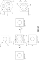
- FIG. 11 shows an illustrative schematic and projection of a single interlockable reef block 56 in accordance with another embodiment of the present disclosure.
- Block 56 includes four female formations 22 on respective faces.
- the inter-engagable members on the exterior of the reef block are such that one end of one artificial reef block can be engaged with the complementary end formation of another reef block to form an interlocked arrangement forming something akin to a single monolithic structure.
- Female engagement members 22 are at 90 degrees to one another and may be used to form a cross piece of a monolithic structure.
- Interlockable reef block 56 includes entrances 12 which are the points at which water, fish and other sea creatures may enter. They allow a passage from the exterior to interior of the artificial reef block 56 and are situated in the centre of all of the two remaining faces. There are cylindrical spaces 13 extending inward from respective exterior faces of the reef block 56, to the interior spherical cavity 52.
- Fig. 12 shows an illustrative schematic and projection of a single interlockable reef block 58 in accordance with another embodiment of the present disclosure.
- Block 58 includes four male formations 20 on respective faces.
- the inter-engagable members on the exterior of the reef block are such that one end of one artificial reef block can be engaged with the complementary end formation of another reef block to form an interlocked arrangement forming something akin to a single monolithic structure.
- Male engagement members 20 are at 90 degrees to one another and may be used to form a cross piece of a monolithic structure.
- Interlockable reef block 58 includes entrances 12 which are the points at which water, fish and other sea creatures may enter. They allow a passage from the exterior to interior of the artificial reef block 56 and are situated in the centre of all of the two remaining faces.
- There are cylindrical spaces 13 extending inward from respective exterior faces of the reef block 58, to the interior spherical cavity 14.
- Fig 13 shows an illustrative schematic and projection of the single artificial reef block 18 of Fig. 5 .
- Block 18 includes male and female formations on respective faces of two of the exterior faces 20 and 22 respectively.
- Fig 14 shows an illustrative schematic and projection of a single interlockable reef block 60 in accordance with another embodiment of the present disclosure.
- Block 60 includes three female formations 22 on three respective faces.
- the inter-engagable members on the exterior of the reef block are such that one end of one artificial reef block can be engaged with the complementary end formation of another reef block to form an interlocked arrangement forming something akin to a single monolithic structure.
- Female engagement members 22 are at 90 degrees to one another and may be used to form a T-piece of a monolithic structure.
- Interlockable reef block 60 includes three entrances 12 which are the points at which water, fish and other sea creatures may enter. They allow a passage from the exterior to interior of the artificial reef block 60 and are situated in the centre of all of the two remaining faces. There are cylindrical spaces 13 extending inward from respective exterior faces of the reef block 60, to the interior spherical cavity 14.
- Fig 15 shows an illustrative schematic and projection of the single artificial reef block 10 of Fig. 1 .
- any reference to "one embodiment” or “an embodiment” means that a particular element, feature, structure, or characteristic described in connection with the embodiment is included in at least one embodiment.
- the appearances of the phrase “in one embodiment” or the phrase “in an embodiment” in various places in the specification are not necessarily all referring to the same embodiment.
- the terms “comprises,” “comprising,” “includes,” “including,” “has,” “having” or any other variation thereof, are intended to cover a non-exclusive inclusion.
- a process, method, article, or apparatus that comprises a list of elements is not necessarily limited to only those elements but may include other elements not expressly listed or inherent to such process, method, article, or apparatus.
- “or” refers to an inclusive or and not to an exclusive or. For example, a condition A or B is satisfied by any one of the following: A is true (or present) and B is false (or not present), A is false (or not present) and B is true (or present), and both A and B are true (or present).
- joints other than dovetail joints may be used such as mortise and tenon joints, finger joints, box joints, tongue and groove joints and dowel joints.
- joints other than dovetail joints may be used such as mortise and tenon joints, finger joints, box joints, tongue and groove joints and dowel joints.
- Embodiments in accordance with the present invention have been described with reference to a monopile support structure for a wind turbine.
- One or more embodiments may be applicable and usable for support structures other than monopile structures such as tripods for example.
- embodiments of the present invention are not limited to inhibiting sea bed scouring around support structures for wind turbines but may be used to inhibit scouring around any structure located on a seabed. They may also be used for other purposes such as for creating artificial reefs, mooring points, shellfish farm lines, anti-trawling structures and other underwater structures and even above water structures.
- reef block 10 may include use of human remains to be cast into the concrete mix to from a personal burial/memorial reef; use as a mangrove planter whereby the hard substrate retains the plant in its place while the hole provides room for roots and water or mineral absorption. This may be particularly useful because mangroves cover coast lines all over the world and act as a natural sea defence.
- the reef block 10 may be used as a static shellfish farm.
- the structures can act as a natural reef system in which shellfish such as crab, lobster, crayfish and the like can enter the structure naturally and be removed by hand by a diver. This eliminates large strings of crab/lobster pots being placed on the seabed which not only drag along delicate sea beds, but can also break off from their surface buoy and become "ghost "fishing gear (effectively meaning they drift along the seabed trapping animals for years to come with no way of them escaping. With the need for sustainable fishing becoming more relevant there is wide spread need of sustainable farming methods of the sea.
- Off-shore cable protection for the offshore renewable energy sector may be provided by the use of the reef blocks 10 individually or as a monolithic structure.
- the reef blocks 10 In order to transfer the power generated from tidal/wave, solar and wind farms back to shore. Large cables relay the electricity back from the offshore unit to the land based transformer/ substation and these cables are often protected with loose rubble and rock blankets/ bags.
- Portland cement is extremely carbon dioxide intense in its production process.
- Other cements such as PFA (pulverised fly ash), GGBS (or GGBFS) Ground-granulated blast-furnace slag or a magnesium based cement may be used for their beneficial carbon dioxide properties.
- the cement may be a carbon dioxide negative material which absorbs more carbon dioxide in its production then it releases.
- the concrete may also include crushed shellfish shells to entice marine life to the area.
- non-interlocking reef blocks may be curved.
- unconstrained when referring to the water flow path through aperture spaces and the cavity formed by the central cavity should be understood as including arrangements which have a limited number of or indeed no barriers or other objects in the water flow path defined by the apertures and cavity.
- unconstrained may be construed to mean “substantially unconstrained”.
Landscapes
- Engineering & Computer Science (AREA)
- General Engineering & Computer Science (AREA)
- Life Sciences & Earth Sciences (AREA)
- Environmental Sciences (AREA)
- Mechanical Engineering (AREA)
- Environmental & Geological Engineering (AREA)
- Ocean & Marine Engineering (AREA)
- Civil Engineering (AREA)
- Structural Engineering (AREA)
- Animal Husbandry (AREA)
- Zoology (AREA)
- Marine Sciences & Fisheries (AREA)
- Biodiversity & Conservation Biology (AREA)
- Chemical & Material Sciences (AREA)
- Manufacturing & Machinery (AREA)
- Ceramic Engineering (AREA)
- Crystallography & Structural Chemistry (AREA)
- Inorganic Chemistry (AREA)
- Artificial Fish Reefs (AREA)
- Revetment (AREA)
- Laser Beam Processing (AREA)
Description
- The present invention relates to the field of underwater structures, for example artificial reefs, anti-seabed scouring and anti-trawling structures. More particularly, but not exclusively, one or more embodiments relate to stackable and or inter-engageable interlocking blocks which can be positioned underwater to provide strong and or substantially immoveable structures with the ability to allow and encourage marine life inhabitation.
- With the need for offshore wind power capacity expected to increase in the near future, there is likely to be an increase in the number of wind turbines that are installed. An important issue with offshore wind turbines that are fixed to the seabed is the 'scouring' of the sand and silt around the support structure. Scouring of the seabed occurs when mobile sand and silt around the turbine support (often a single pole driven into the seabed and known as a "monopile") is 'eaten away', leaving a large conical hole around the wind turbine support. The following shall use the term "monopile" when referring to a support structure for an off-shore wind turbine for brevity and convenience and the teaching of the disclosure should not be limited by the use of that term noting that more than one support pole may be utilised. Sea bed scouring is caused by changes in the flow pattern of the water around the base of a monopile. Currently, the most common technique to counteract scouring is to dump rock and other such material, typically up to 200,000 tonnes, around the base of the support monopile.
- Another current issue involving the sea is the depletion of the natural habitat on the seabed available for sea creatures and plants. This is partly due to detrimental bottom trawling practices used in commercial fishing, where the seabed is scraped to such an effect that fragile reef systems are destroyed. This has a negative effect on breeding grounds for fish, resulting in depletion of many marine species. There are attempts to mitigate this by enforcing 'no trawl' zones to create reserves where no bottom trawling is permitted. However, this is sometimes ignored by commercial fishermen and it is very hard for the authorities responsible for the care of the no trawl zone to enforce the restriction.
- Known methods of protection include the use of so called 'Czech Hedgehogs', tank traps or other heavy objects placed underwater to block the trawls and deter commercial fishermen. The size of trawls and boats is ever increasing and the current methods to inhibit bottom trawling are becoming inadequate and are now more of a hindrance than the prevention they used to be.
- Attempts to reverse this depletion have resulted in the creation and implementation of artificial marine habitats and structures. Some examples include the sinking of retired ships, bundles of car tyres, concrete breeze blocks and so on.
-
EP1036638A1 discloses a concrete block having comparatively light weight and capable of being manufactured easily and used in various fields of application. -
US6431792B1 discloses an artificial reef structure including various building components that are preformed from concrete and the like. -
WO9913176A1 -
JPH115205A -
JPH10136829 -
JP2001355220 hollow shell wall 3 having a spherical outer surface and inner surface, and the whole body of theshell wall 3 is integrally moulded of concrete, and a number of wall ports 5 is formed in theshell wall 3. - Aspects and embodiments of the present invention have been devised with the foregoing in mind.
- Viewed from a first aspect the present invention provides a module for an underwater structure according to
claim 1. The module comprises a plurality of walls defining a cavity configured such that at least two walls of said plurality of walls confront one another to provide respective stack support surfaces for supporting a said module, said walls are substantially parallel to form complementary stack surfaces, such that one stack surface may rest on a surface and the other complementary stack surface provides a rest surface for another module. Two or more walls of said plurality of walls each comprise an aperture providing a conduit through each two or more walls to said cavity, respective apertures of said two or more walls and said cavity configured to provide a water flow path into, through and from said cavity. The water flow path may be considered unconstrained or at least substantially unconstrained in that water may flow through the apertures and cavity without deviation or interruption other than by the module or cavity walls. In stacked formation an aperture may be occluded or partially occluded but still the module when on its own may provide water pathways which may be considered unconstrained or substantially unconstrained. - The central spherical cavity defined by the plurality of walls of said module substantially provides protection for, and encourages, growth of marine life such as fish, corals, barnacles, shellfish, sea-weed and other flora and fauna. Ingress of water through said apertures in said walls may encourage or promote diffusion of local sea currents through and out of said module. By permitting water flow through the module the formation of "scouring currents" around the module, or a collection of modules, is discouraged compared to an arrangement that blocks water flow. This will significantly reduce local sea-bed scouring around monopile supports for wind turbines and the module itself. The module is particularly suitable as an artificial reef block and for use in combining with other such blocks to form an artificial reef.
- Although water flow into, through and out of the module through the cavity and apertures is unconstrained or substantially unconstrained the presence of the module walls may act to disrupt water flow and promote dispersion of currents thereby avoiding strong current flow in and through the module. Disruption or dispersion of current flow in and through modules may assist in encouraging or promoting marine life growth in the module.
- The substantially parallel stack support surfaces of said module enables said module to be stacked one on top of each other, forming an artificial reef structure. Whereby substantially parallel stack supports relate to two opposing surfaces on the top and bottom of said module arranged to allow efficient stacking of more than one said module.
- Any suitable settable material may be used to form a said module provided it is sufficiently viscous to substantially fill the mould and is not soluble in water when set. Suitably, said walls comprise a masonry material, for example a wall may comprise concrete. Masonry material is relatively heavy and may comprise various brick, rock or other material found in masonry, including metal rods and mesh typically bound together with concrete.
- Furthermore, said module comprises one or more apertures that are configured so that the module walls have sufficient mechanical strength to support at least one said module and the apertures allow substantial ingress of water to a cavity within said module, for example said cavity may comprise curved walls configured to provide a support arch for one or more of said plurality of walls. Said cavity may act as a shelter for marine life such as shells, crustaceans, fish, and other flora and fauna.
- In an embodiment of the module said cavity comprises curved walls configured to provide a vault-like support for one or more of said plurality of walls.
- Additionally, the module may include a plurality of textured or smooth walls, wherein at least one of said plurality of walls comprises a rough outer surface to promote growth of certain species of marine life.
- Viewed from a second aspect, the module further comprises an engagement formation on at least one of said plurality of walls configured to engage with a complementary formation disposed on an element external to said module, wherein said engagement formation is disposed on an outer wall of said one or more plurality of walls. This allows one or more of said modules to be interlocked together to form a substantially rigid monolithic structure.
- Said engagement formation being disposed on at least two of said plurality of walls and wherein a first said engagement on a first of said at least two of said plurality of walls is complementary to a second said engagement formation on a second of said at least two or more plurality of walls. Said at least two of said plurality of walls oppose each other so as to provide respective stack surfaces.
- First and second engagement portions on said at least two of said plurality of walls are configured for engagement with a laterally disposed element external to said module. The engagement may be a vertically disposed element external to said module.
- In at least one embodiment there is provided an external element configured to engage with a module. Such an element may comprise a part of a larger structure such as a jetty or sea wall or the like. Suitably, the external element may be another module or at least comprise another of the modules.
- According to the invention, there is provided a method of manufacturing a module for an artificial reef block according to
claim 13, the method comprising placing an object having the shape of a cavity to be formed in a module to be manufactured in a mould comprising an inner configuration corresponding to the outer configuration of said module; placing a first and second ring to extend from respective first and second inner walls to said object; filling said mould with a settable mixture comprising masonry material; and allowing said settable mixture to set and removing said module from said mould. - Suitably, the method further comprises removing said first and second ring prior to removing said module from said mould to allow removal of said object. Said object that forms said cavity is collapsible so as to aid removal of said object from said module with ease and may comprise an inflatable object that is deflatable so as to aid removal of said object from said module.
- Additionally the method may comprise removing some partially set mixture from an exterior or interior wall or part thereof to provide a rough surface so as to expose aggregate surfaces. This allows for a variety of surface textures for adhesion of many different marine life species which require a variety of said textures.
- Viewed from a fourth aspect there is provided a structure comprising a plurality of modules, wherein a first group of said plurality of modules support a second group of said plurality of modules, a stack surface of each of said second group of said plurality of modules resting on one or more stack surfaces of said first group of said plurality of modules.
- In particular, wherein adjacent modules in a lateral direction are interlocked with each other via said engagement formation and complementary engagement formation for form a substantially rigid monolithic structure for use in sea defence, artificially reef, fishing, anti-trawl, and anti-scour applications.
- In a particular embodiment of the structure adjacent modules in a vertical direction are interlocked with each other via said engagement formation and complementary engagement formation.
- Said walls of said modules may be a plastic material to discourage growth of marine life and aid to removal of said module at the end of its life. Said plastic material may comprise a suitable thermoplastic such as Low Density Polyethylene (LDPE), High Density Polyethylene (HDPE), Polypropylene, Polyvinyl Chloride (PVC), Polyethylene Terephthalate (PET), recycled plastic, or other similar materials. The method of construction could be, but not be limited to, extrusion moulding, injection moulding, vacuum forming, stretch moulding, or blow-moulded.
- One or more specific embodiments in accordance with aspects of the present invention will now be described, by way of example only, and with reference to the following drawings in which:
-
Fig. 1 schematically illustrates an isometric projection of an embodiment of an artificial reef block in accordance with an embodiment of the present invention; -
Fig. 2 schematically illustrates a cross section of the artificial reef block shown infig. 1 ; -
Fig. 3 schematically illustrates example clusters of an artificial reef block in accordance with an embodiment of the present invention; -
Fig. 4 schematically illustrates a method of construction of the artificial reef block; -
Fig. 5 schematically illustrates an isometric projection of one embodiment of an interlockable artificial reef block in accordance with an embodiment of the present invention; -
Fig. 6 schematically illustrates a plurality of the artificial reef block embodiment shown infig. 5 arranged to form a seawall or artificial reef; -
Fig. 7 schematically illustrates another embodiment of an interlockable artificial reef block with male and female formations for mutual interengagement; -
Fig. 8 schematically illustrates the embodiment shown infig. 7 from other perspectives; -
Fig 9 . Schematically illustrates another embodiment of the interlocking artificial reef blocks in accordance with the present invention, in which the artificial reef blocks forms a ring-like, monolithic structure; -
Fig. 10 schematically illustrates an isometric projection of one embodiment of an interlockable artificial reef block in accordance with an embodiment of the present invention; -
Fig. 11 schematically illustrates an isometric projection of one embodiment of an interlockable artificial reef block in accordance with an embodiment of the present invention; -
Fig. 12 schematically illustrates an isometric projection of one embodiment of an interlockable artificial reef block in accordance with an embodiment of the present invention; -
Fig. 13 schematically illustrates another embodiment of an interlockable artificial reef block with male and female formations for mutual interengagement; -
Fig. 14 schematically illustrates an isometric projection of one embodiment of an interlockable artificial reef block in accordance with an embodiment of the present invention; and -
Fig. 15 schematically illustrates an isometric projection of an embodiment of an artificial reef block in accordance with an embodiment of the present invention. -
Fig. 1 is an illustrative schematic drawing of anartificial reef block 10 in accordance with an embodiment of the present invention. Such areef block 10 may be utilised for the promotion of growth of marine wildlife, for example; coral; oysters; barnacles; seaweed and the like. Such areef block 10 may also provide protection for various fish species during their early life development by way of the centralspherical cavity 14 providing shelter. The configuration of theartificial reef block 10 is cuboid, and is generally but not exclusively, of a concrete mixture. One specific mix is made of stone, sand, cement, high-range plasticiser, micro silica and silica fibres. An illustrative ratio of the main constituents could be 3 parts stone or substrate, 2 parts sand, 1 part cement, 1 part micro silica. Additionally, 100ml of plasticiser (ADVA 650), and 10-20g of fibres are incorporated and mixed in to the above mix for a module of 1 m3. 100 ml corresponds to 0.0001 m3 and therefore is not a significant ratio in terms of parts, and considered to be an additive to the main mix. There are a total of seven parts contributing to the 1 m3 reef block, therefore one part corresponds to a volume of 1/7 m3. The additional fibres used are typically a high-performance, monofilament, polypropylene fibre developed as a crack controlling additive for cementitious materials. It is used to inhibit the formation of small cracks which can occur through plastic shrinkage, premature drying and early thermal changes, in order to provide utilisation of the intrinsic properties of the hardened cementitious material. - To increase the strength of the concrete mix, the water content generally is reduced so as to lower the water-cement ratio, which causes the mixture to be less workable. The high-range plasticizer is a chemical admixture used for improving the workability of the mix; it is used as a dispersant to avoid particle aggregation; and used to improve flow characteristics. The mix is designed to have a relatively low PH of around 8.3 compared with conventional mixes of concrete, which typically has a PH level of 11-13. This will be more suitable for marine life adhesion.
- The micro silica and silica fibres aid in strengthening the
artificial reef block 10 and give the mixture a predicted life in seawater of around 500 years. The micro silica and silica fibres also help to minimise the leaching out of any concrete toxins into the environment. Other heavy materials may be used. In some embodiments, an aggregate is added to the mixture and the individual external faces may have a rough surface to promote the growth of barnacles, various algae and other flora and fauna. This may be achieved by gently washing off a small layer of concrete on the exterior of the cube exposing the aggregate before it is fully cured. This gives a range of surface textures which may appeal to a range of sea flora and fauna species. In other embodiments the internal and external surfaces may be relatively smooth, which also has its advantages for other species of marine life. - In the described embodiment, the
central cavity 14 is spherical having its centre aligned close to the centre of the surrounding edges of theblock 10. The diameter of the cavity is smaller than the length of the smallest face of theblock 10, such that it does not extend to the exterior of theblock 10. Theentrances 12 show the points at which fish and other sea creatures may enter. They allow a passage from the exterior to interior of the artificial reef block and are situated in the centre of all of the external faces. There arecylindrical spaces 13 extending inward from respective exterior faces of thereef block 10, to the interiorspherical cavity 14. Thecentral cavity 14 also allows water to flow freely through theartificial reef block 10. Two cross-sectional views labelled section AA and section BB are shown infig. 2a and fig. 2b respectively. -
Figs. 2a and 2b show the two cross-sectional views across the lines labelled AA and BB respectively shown infig. 1 forartificial reef block 10. The cross-sections showcylindrical spaces 13, centralspherical cavity 14, side entrances 12, andside walls 16. Marine life can enter or exit thespherical centre cavity 14 of theartificial reef block 10 through any of the circular entrances 12. Similarly water may pass through relatively uninhibited, allowing a current to impinge upon the artificial reef blocks without hitting a completely solid surface; for this reason reef blocks 10 may also be used to reduce currents and therefore as a sea barrier. - Generally an
artificial reef block 10 can be submerged underwater individually or as part of a cluster of two or more blocks. Thespherical cavity 14 creates a uniform centre of arches that enable the reef blocks 10 to be weight bearing and so may be stacked to a relatively large number of layers, for example up to 10 layers. Unlike other sea walls and sea defences, the sphericalcentral cavity 14, with the entrances from the exterior to interior allows some water current to pass through the wall hence acting to reduce the force impinging upon it due to the current. One skilled in the art can conceive of various combinations of sizes and, shapes of artificial reef blocks to form a variety of structures. - Some illustrative structures are shown in
figs. 3a, 3b, and 3c . Two sizes of theartificial reef block 10 are illustrated in various structures and arrangements forming conditions suitable for the promotion of marine life and flora and fauna. The cuboid structure allows the reef blocks 10 to be easily stacked, and the central cavity forms a plurality of central arches and columns for bearing the weight of the artificial reef blocks. The illustrative structures may create a large protected environment inside of the artificial reef blocks for marine life to thrive. - The method of construction of an
artificial reef block 10 in accordance with an embodiment of the present invention comprises placing a sphericalinflatable bladder 9 inside a cuboid crate 5. The size of thespherical bladder 9 corresponds to the inside dimension of the central spherical cavity section (fig. 1 ,14 ) required for theartificial reef block 10; and the inner dimensions of the cuboid crate 5 match that of the outer dimensions of the artificial reef block (1x1x1m) 10. Six edging rings 15 are used to position the spherical bladder in the centre of the cuboid crate 5. The thickness or length of respective edging rings 15 are greater than or equal to the difference between the diameter of the inside of the cuboid crate 5 and thespherical bladder 9. - For example, if the inside of the cuboid crate 5 is 1x1x1m and the outer diameter of the
spherical bladder 9 is 0.8m, then the width of each of the six edging rings will be greater than 0.1m. The larger theentrance 12 required, the larger the diameter of the six edging rings required. The larger the diameter of a ring, the greater its axial length 21 will need to be, because the distance between the outer of thespherical bladder 9 and inner of the cuboid crate 5 increases with ring diameter. The six edging rings form a join between the inside of the small cuboid crate 5 and the outer surface of thespherical bladder 9. - Once all of the rings are in place, the
space 11 between the inner walls of the cuboid crate 5 and the outer surface of thespherical bladder 9 can be filled with a concrete mix. - In the described embodiment, the six edging rings 15 are cylindrical in shape, with length 21 but are not limited to such a configuration. One skilled in the art may envisage embodiments in which the rings are such that the
walls 13 are conical, angled, convex or concave for example. They may also be other shapes, and not always a circular cross-section, such that they create a join between the six inner surfaces of the cuboid crate 5 and the outer surface of thespherical bladder 9. Respective edging rings 15 do not need to be the same size, diameter, or thickness so long as the continuous join between the six inner surfaces of the small cuboid crate 5 and the outer surface of thespherical bladder 9 is maintained. For example, one could have smaller rings on two of the faces and so on. - The cuboid crate 5 may be constructed of wood, metal, plywood, fibreglass, plastic or any other similar material. One skilled in the art can easily envisage a crate 5 constructed of any or a combination of any of the aforesaid materials.
- If an artificial reef using one or more embodiments of the present invention is to be built in a region where there are strong currents and under water turbulence is present, a much stronger structure is required than might be achieved using the aforesaid arrangements. This is addressed in another embodiment of the invention illustrated in
Fig. 5 , which shows a schematic of a singleartificial reef block 18 with male and female formations on respective faces of two of the exterior faces 20 and 22 respectively. The inter-engageable members on the ends of the reef block are such that one end of one artificial reef block can be engaged with the complementary end formation of another reef block to form an interlocked arrangement forming something akin to a single monolithic structure. - The term "monolithic" is used herein to refer to a structure that substantially appears and acts as a single structure although comprised of smaller components, described here with interengagement formations, which may be interlocking formations. Two or more artificial reef blocks can be engaged in this way, allowing formation of as large a monolithic structure as required for the given application. This may include but not be limited to sea defences, large artificial reef structures, submerged breakwaters and anti-trawling devices for example.
- Similar to other embodiments,
artificial reef block 18 hascylindrical spaces 13,spherical centre 14 withentrances 12. The number of entrances is reduced to four in this embodiment due to the male andfemale formations female formations fig. 5 , the male and female formations are in the form of a sliding dovetail like joint. - The sliding dovetail joint provides the interlocking strength achieved by a conventional dovetail joint, but with the ability of some vertical movement. The
male formation 20 slides into thefemale formation 22 and one may be engaged with the other by vertically offsetting two artificial reef blocks such that the bottom face of oneartificial reef block 18, is opposite to top face of another artificial reef block; aligning rear faces 24 on oneartificial reef block 18 to the front faces 26 of thesecond reef block 18; and then providing a vertical motion such that the top face of oneartificial reef block 18 is in alignment with the secondartificial reef block 18 and lowering onereef block 18 with respect to the other to engage respective male and female formations, hence interlocking the two artificial reef blocks 18 together. - Thus two or more artificial reef blocks may be interlocked together to form a long, substantially immoveable monolithic structure with high strength due to the interengaging formations. Although the described embodiment uses a sliding dovetail joint, one skilled in the art may envisage other joining mechanisms which offer similar strength and ability to for a monolithic structure.
- The
artificial reef block 18 shown infig. 5 is also capable of being stacked which will allow even larger structures to be formed with the added strength of the horizontal coupling of the sliding dovetail joints 40. Illustrative structures are shown infig. 6 a) and 6 b). Figs. 6 a) and 6 b) show a plurality of interlocked artificial reef blocks 18 forming a large monolithic structure which, due to the centralspherical cavities 14 and entrances 12, allows currents to flow through the barrier. The centralspherical cavities 14 and entrances 12 act so as to reduce the local current and thereby reduce the scouring effect around subsea structures such as monopiles for wind turbines and the like.Fig. 6b also shows a method of stacking the artificial reef blocks 18. Here anartificial reef block 19 is shown to be moved in a downward direction to add to the large monolithic structure. Itsmale formation 20 is aligned with afemale formation 22 on another artificial reef block such that when 19 is moved vertically downward, it interengages with anotherartificial reef block 18 forming a strong male-female interlocking joint 40. Here the bottom wall of theartificial reef block 19 is supported by the top walls of the artificial reef blocks it is placed on. This is the manner of the stack support provided to each subsequent layer of blocks. - One skilled in the art will understand that in stacked formation and aperture may be occluded or partially occluded, but will still act to allow the flow of water through the structure.
- Where an even greater strength in a monolithic structure is required, at least one other embodiment may be envisioned.
Fig. 7 illustrates another variant of the artificial reef block and is similar to the embodiment shown infig. 5 . Anartificial reef block 28 includesentrances 12,cylindrical space 13, centralspherical space 14,male formation 20, correspondingfemale formation 22 andvertical dowels 30. It is thevertical dowels 30 that distinguishes this particular embodiment to the one infig. 6 (6a, and 6b ). Thevertical dowels 30 have a corresponding female formation on the opposite face of theartificial reef block 28. In this embodiment the dowels are positioned on one face of theartificial reef block 28 with the corresponding female part disposed on the opposing face of a second artificial reef block.Fig. 7 shows twovertical dowels 30, but in other embodiments not shown any suitable number may be used. The shape and form of the dowel and corresponding hole may be other than cylindrical as well. In this illustrative embodiment the dowels are cylindrical in shape but other shapes may be used, for example square or polygon cross-section dowels. -
Fig. 7 shows an examplemonolithic structure 32 which incorporates thedowels 30. In this embodiment, the individual artificial reef blocks 28 are stacked such that each layer is offset by half the length of the artificial reef block. This is similar to a common running bond used in brick laying. In other embodiments one may use an arrangement that uses different patterns and types of offsets and embodiments of the present invention is are not limited to the current embodiment or embodiments discussed herein. -
Fig. 8a shows a different perspective of themonolithic structure 32 illustrated inFig. 7 .Fig. 8 a) shows a plurality of interlocked artificial reef blocks 28 forming a large monolithic structure, which due to the centralspherical cavities 14 and entrances 12, allow currents to flow through thebarrier 32. The centralspherical cavities 14 and entrances 12 will act so as to reduce the local current and thereby reduce the scouring effect around subsea structures such as the monopile of wind turbines and the like.Fig. 8 a) also shows the method of stacking the artificial reef blocks 28. Here anartificial reef block 29 is shown to be moved in a downward direction to add to the large monolithic structure. Itsmale formation 20 is aligned with afemale formation 22 on another artificial reef block such that when 19 is moved vertically downward, it interlocks together with another reef block and forms a strong male-female interlocking joint 40. Thedowels 30 align with theholes 34 thereby creating a strong interlocking between successive stacked rows. -
Fig. 8b shows a plan view of three interlocked artificial reef blocks 28 with the dowels in place. Themale projection 20 is interlocked with afemale projection 22 on anotherartificial reef block 28 to form the male-female interlocking joint 40. It also shows the relative position of thedowels 30 to thefemale holes 34 in this embodiment. They are diagonally opposite in the plane shown, so that when stacked they overlap by half the length of theartificial reef block 28. - When stacked, the vertical dowels act to add strength vertically between adjacent rows of artificial reef blocks. This inhibits movement of vertically adjacent rows with respect to each other due to water pressure from undersea currents and forces.
- In another embodiment of the invention, an interlockable artificial reef block may be curved so that when a plurality of artificial reef blocks are coupled together they form a circular monolithic structure rather than a linear monolithic structure. An example is shown in
fig. 9 a). Fig 9 a) shows a schematic plan view of a circularmonolithic structure 36. In a particular embodiment it is in the form of a ring with an outer diameter of 12.732m, and thickness 1m.Structure 36 is comprised of twenty curved artificial reef blocks 38. Thus each artificial reef block fits inside of an 18 degree sector of the circle formed by the outer diameter. The individual curved artificial reef blocks have an outer radius of 6.366m 44, an inner radius of 5.366m 46, and both radii are concentric meaning they have a common centre 42. Each of the curved artificial reef blocks 38 have a sphericalcentral space 14 and entrances 12. They are similar to the other embodiments of the current invention in that they have the male formation on one end, and the female formation on the opposing end to form of a sliding dovetail joint. Both can be brought into an interlockingarrangement 40 which will give the structure great strength from subsea currents and forces. Thespherical cavities 14 and entrances 12 allow the currents to flow through and around the support monopile of a wind turbine, and therefore reduce the effect of seabed scouring that occurs. A 3D isometric projection of this embodiment is illustrated infig. 9b . - The illustrated embodiment is for a fixed radius structure, but can be changed to accommodate larger or smaller monopiles or other curved circular configurations.
- In another embodiment of the invention the material used for the construction of the artificial reef block may be comprised of a high-impact, durable plastic material so as to discourage the growth of marine life, while still acting to reduce the seabed scour around fixed structures. This will allow the artificial reef blocks to be removed easily when the structure is required to be removed. For example, some wind farms have the requirement that all aspects of the wind turbines must be removed when their end of life is reached, which may include the wind turbine itself, support pole, any scouring protection and the like. In this instance, the artificial reef blocks employed as scour protection will be required to be removed. With 25 years of marine life growth, this will be very difficult to achieve, and therefore a solution which inhibits marine life growth will need to be employed.
- Some examples of suitable material are thermoplastics such as Low Density Polyethylene (LDPE), High Density Polyethylene (HDPE), Polypropylene, Polyvinyl Chloride (PVC), Polyethylene Terephthalate (PET), recycled plastic, or other similar materials. The method of construction could be, but not be limited to, extrusion moulding, injection moulding, vacuum forming, stretch moulding, or blow-moulded.
-
Fig. 10 shows an illustrative schematic and projection of a singleinterlockable reef block 50 in accordance with another embodiment of the present disclosure and is similar to that shown inFig. 5 .Block 50 includes male and female formations on respective faces of two of the exterior faces 20 and 22 respectively. The inter-engagable members on the exterior of the reef block are such that one end of one artificial reef block can be engaged with the complementary end formation of another reef block to form an interlocked arrangement forming something akin to a single monolithic structure.Engagement members Interlockable reef block 50 includesentrances 12 which are the points at which water, fish and other sea creatures may enter. They allow a passage from the exterior to interior of theartificial reef block 50 and are situated in the centre of all of the external faces. There arecylindrical spaces 13 extending inward from respective exterior faces of thereef block 50, to the interiorspherical cavity 14. -
Fig. 11 shows an illustrative schematic and projection of a singleinterlockable reef block 56 in accordance with another embodiment of the present disclosure.Block 56 includes fourfemale formations 22 on respective faces. The inter-engagable members on the exterior of the reef block are such that one end of one artificial reef block can be engaged with the complementary end formation of another reef block to form an interlocked arrangement forming something akin to a single monolithic structure.Female engagement members 22 are at 90 degrees to one another and may be used to form a cross piece of a monolithic structure.Interlockable reef block 56 includesentrances 12 which are the points at which water, fish and other sea creatures may enter. They allow a passage from the exterior to interior of theartificial reef block 56 and are situated in the centre of all of the two remaining faces. There arecylindrical spaces 13 extending inward from respective exterior faces of thereef block 56, to the interiorspherical cavity 52. -
Fig. 12 shows an illustrative schematic and projection of a singleinterlockable reef block 58 in accordance with another embodiment of the present disclosure.Block 58 includes fourmale formations 20 on respective faces. The inter-engagable members on the exterior of the reef block are such that one end of one artificial reef block can be engaged with the complementary end formation of another reef block to form an interlocked arrangement forming something akin to a single monolithic structure.Male engagement members 20 are at 90 degrees to one another and may be used to form a cross piece of a monolithic structure.Interlockable reef block 58 includesentrances 12 which are the points at which water, fish and other sea creatures may enter. They allow a passage from the exterior to interior of theartificial reef block 56 and are situated in the centre of all of the two remaining faces. There arecylindrical spaces 13 extending inward from respective exterior faces of thereef block 58, to the interiorspherical cavity 14. -
Fig 13 shows an illustrative schematic and projection of the singleartificial reef block 18 ofFig. 5 .Block 18 includes male and female formations on respective faces of two of the exterior faces 20 and 22 respectively. -
Fig 14 shows an illustrative schematic and projection of a singleinterlockable reef block 60 in accordance with another embodiment of the present disclosure.Block 60 includes threefemale formations 22 on three respective faces. The inter-engagable members on the exterior of the reef block are such that one end of one artificial reef block can be engaged with the complementary end formation of another reef block to form an interlocked arrangement forming something akin to a single monolithic structure.Female engagement members 22 are at 90 degrees to one another and may be used to form a T-piece of a monolithic structure.Interlockable reef block 60 includes threeentrances 12 which are the points at which water, fish and other sea creatures may enter. They allow a passage from the exterior to interior of theartificial reef block 60 and are situated in the centre of all of the two remaining faces. There arecylindrical spaces 13 extending inward from respective exterior faces of thereef block 60, to the interiorspherical cavity 14. -
Fig 15 shows an illustrative schematic and projection of the singleartificial reef block 10 ofFig. 1 . - As used herein any reference to "one embodiment" or "an embodiment" means that a particular element, feature, structure, or characteristic described in connection with the embodiment is included in at least one embodiment. The appearances of the phrase "in one embodiment" or the phrase "in an embodiment" in various places in the specification are not necessarily all referring to the same embodiment.
- As used herein, the terms "comprises," "comprising," "includes," "including," "has," "having" or any other variation thereof, are intended to cover a non-exclusive inclusion. For example, a process, method, article, or apparatus that comprises a list of elements is not necessarily limited to only those elements but may include other elements not expressly listed or inherent to such process, method, article, or apparatus. Further, unless expressly stated to the contrary, "or" refers to an inclusive or and not to an exclusive or. For example, a condition A or B is satisfied by any one of the following: A is true (or present) and B is false (or not present), A is false (or not present) and B is true (or present), and both A and B are true (or present).
- In addition, use of the "a" or "an" are employed to describe elements and components of the invention. This is done merely for convenience and to give a general sense of the invention. This description should be read to include one or at least one and the singular also includes the plural unless it is obvious that it is meant otherwise.
- In view of the foregoing description it will be evident to a person skilled in the art that various modifications may be made within the scope of the invention. For example, joints other than dovetail joints may be used such as mortise and tenon joints, finger joints, box joints, tongue and groove joints and dowel joints. Embodiments in accordance with the present invention have been described with reference to a monopile support structure for a wind turbine. One or more embodiments may be applicable and usable for support structures other than monopile structures such as tripods for example. Additionally, embodiments of the present invention are not limited to inhibiting sea bed scouring around support structures for wind turbines but may be used to inhibit scouring around any structure located on a seabed. They may also be used for other purposes such as for creating artificial reefs, mooring points, shellfish farm lines, anti-trawling structures and other underwater structures and even above water structures.
- Other uses of the
reef block 10 may include use of human remains to be cast into the concrete mix to from a personal burial/memorial reef; use as a mangrove planter whereby the hard substrate retains the plant in its place while the hole provides room for roots and water or mineral absorption. This may be particularly useful because mangroves cover coast lines all over the world and act as a natural sea defence. - Moreover, the
reef block 10 may be used as a static shellfish farm. The structures can act as a natural reef system in which shellfish such as crab, lobster, crayfish and the like can enter the structure naturally and be removed by hand by a diver. This eliminates large strings of crab/lobster pots being placed on the seabed which not only drag along delicate sea beds, but can also break off from their surface buoy and become "ghost "fishing gear (effectively meaning they drift along the seabed trapping animals for years to come with no way of them escaping. With the need for sustainable fishing becoming more relevant there is wide spread need of sustainable farming methods of the sea. - Off-shore cable protection for the offshore renewable energy sector may be provided by the use of the reef blocks 10 individually or as a monolithic structure. In order to transfer the power generated from tidal/wave, solar and wind farms back to shore. Large cables relay the electricity back from the offshore unit to the land based transformer/ substation and these cables are often protected with loose rubble and rock blankets/ bags.
- Although one example of the concrete mix mentions Portland cement, the present disclosure is not limited to just that. Portland cement is extremely carbon dioxide intense in its production process. Other cements such as PFA (pulverised fly ash), GGBS (or GGBFS) Ground-granulated blast-furnace slag or a magnesium based cement may be used for their beneficial carbon dioxide properties. The cement may be a carbon dioxide negative material which absorbs more carbon dioxide in its production then it releases.
- Furthermore, the concrete may also include crushed shellfish shells to entice marine life to the area.
- Although curved interlocking reef blocks have been described non-interlocking reef blocks may be curved.
- The terms used herein should be construed in context. As one example, the term "unconstrained" when referring to the water flow path through aperture spaces and the cavity formed by the central cavity should be understood as including arrangements which have a limited number of or indeed no barriers or other objects in the water flow path defined by the apertures and cavity. The term "unconstrained" may be construed to mean "substantially unconstrained".
- The scope of the present disclosure includes any novel feature or combination of features disclosed therein either explicitly or implicitly or any generalisation thereof irrespective of whether or not it relates to the claimed invention or mitigate against any or all of the problems addressed by the present invention. The applicant hereby gives notice that new claims may be formulated to such features during prosecution of this application or of any such further application derived therefrom. In particular, with reference to the appended claims, features from dependent claims may be combined with those of the independent claims and features from respective independent claims may be combined in any appropriate manner and not merely in the specific combinations enumerated in the claims.
Claims (15)
- A module (10, 18, 28) for an underwater structure, the module being cuboid in shape and comprising a plurality of walls defining a cavity (14) configured such that at least two walls of said plurality of walls confront one another to provide respective stack support surfaces for supporting a said module (10, 18, 28), wherein two or more walls of said plurality of walls each comprise an aperture (12) providing a conduit through each of said two or more walls to said cavity (14), respective apertures (12) of said two or more walls and said cavity (14) configured to provide a water flow path into, through and from said cavity (14); wherein the respective apertures each comprise a cylindrical space (13) extending inward from their respective exterior faces to said cavity (14) and
wherein said cavity (14) comprises curved walls forming a central spherical cavity (14), the curved walls configured to provide a support arch for one or more of said plurality of walls. - A module (10, 18, 28) according to claim 1, wherein said walls comprise a masonry material, for example wherein said masonry material is concrete.
- A module (10, 18, 28) according to any preceding claim, wherein said cavity and or apertures are configured to provide sufficient mechanical strength to support at least one said module (10, 18, 28), preferably to support up to five of said module, more preferably up to ten of said module.
- A module (10, 18, 28) according to claim 2 or claim 3, wherein said cavity comprises curved walls configured to provide a vault-like support for one or more of said plurality of walls, optionally wherein at least one of said plurality of walls comprises a rough outer surface.
- A module (18, 28) according to any preceding claim, further comprising an engagement formation (20, 30) on at least one of said plurality of walls configured to engage with a complementary formation (22, 34) disposed on an external element external to said module (18, 28); for example wherein said engagement formation (20, 22, 30, 34) is disposed on an outer wall of said one or more plurality of walls.
- A module (18, 28) according to claim 5, further comprising a said engagement formation (20, 22, 30, 34) on at least two of said plurality of walls and wherein a first said engagement (20, 30) on a first of said at least two of said plurality of walls is complementary to a second said engagement formation (22, 34) on a second of said at least two or more plurality of walls.
- A module according to claim 6, wherein said at least two of said plurality of walls oppose each other; optionally wherein said first and second engagement portions on said at least two of said plurality of walls are configured for engagement with a laterally disposed element external to said module; optionally wherein said walls comprise a plastic material.
- A module (28) according to claim 7, wherein said first and second engagement portions (30, 34) on said at least two of said plurality of walls are configured for engagement with a vertically disposed element (30, 34) external to said module (28); and for example wherein, said at least two of said plurality of walls provide said respective stack surfaces.
- An external element configured to engage with a module according to any of claim 5 to claim 8, wherein said external element comprises a module according to any of claim 1 to claim 4.
- A structure (32, 36) comprising a plurality of modules (10, 18, 28) according to any preceding claim, wherein a first group of said plurality of modules (10, 18, 28) support a second group of said plurality of modules (10, 18, 28), a stack surface of each of said second group of said plurality of modules (10, 18, 28) resting on one or more stack surfaces of said first group of said plurality of modules (10, 18, 28).
- A structure (32, 36) according to claim 10 when dependent on any of claim 5 to claim 9, wherein adjacent modules (18, 28) in a lateral direction are interlocked with each other via said engagement formation and complementary engagement formation (20, 22).
- A structure (32, 36) according to claim 10 when dependent on any of claim 5 to claim 9, or according to claim 11, wherein adjacent modules in a vertical direction are interlocked with each other via said engagement formation (30, 34) and complementary engagement formation (30, 34).
- A method of manufacturing a module (10, 18, 28) for an artificial reef according to claim 1, the method comprising:placing an object (9) having the shape of a spherical cavity to be formed in a module (10, 18, 28, 38) to be manufactured in a mould comprising an inner configuration corresponding to the outer configuration of said module;placing a first and second ring (15) to extend from respective first and second inner walls to said object, each ring having the shape of a respective aperture to be formed in the wall of a module to be manufactured;filling said mould with a settable mixture (11) comprising masonry material; andallowing said settable mixture (11) to set and removing said module from said mould.
- A method according to claim 13, further comprising removing said first and second ring (15) prior to removing said module from said mould; optionally wherein said object (9) is collapsible so as to remove said object from said module; for example wherein said object (9) is an inflatable object and is deflatable so as to remove said object from said module.
- A method according to any of claim 13, or claim 14, further comprising removing partially set mixture from an exterior wall or part thereof to provide a rough surface; for example wherein said removing partially set mixture exposes aggregate surfaces.
Applications Claiming Priority (2)
| Application Number | Priority Date | Filing Date | Title |
|---|---|---|---|
| GB1620752.4A GB2557321C (en) | 2016-12-06 | 2016-12-06 | Apparatus for an artificial reef and method |
| PCT/GB2017/053678 WO2018104734A1 (en) | 2016-12-06 | 2017-12-06 | Apparatus for an artificial reef and method |
Publications (3)
| Publication Number | Publication Date |
|---|---|
| EP3551804A1 EP3551804A1 (en) | 2019-10-16 |
| EP3551804B1 true EP3551804B1 (en) | 2025-06-18 |
| EP3551804C0 EP3551804C0 (en) | 2025-06-18 |
Family
ID=58159546
Family Applications (1)
| Application Number | Title | Priority Date | Filing Date |
|---|---|---|---|
| EP17818606.0A Active EP3551804B1 (en) | 2016-12-06 | 2017-12-06 | Module for an artificial reef and method |
Country Status (11)
| Country | Link |
|---|---|
| US (2) | US12091829B2 (en) |
| EP (1) | EP3551804B1 (en) |
| JP (1) | JP7212944B2 (en) |
| KR (2) | KR20230145135A (en) |
| CN (1) | CN110268118A (en) |
| AU (1) | AU2017371625B2 (en) |
| ES (1) | ES3041122T3 (en) |
| GB (2) | GB2569716B (en) |
| MX (1) | MX2019006562A (en) |
| PL (1) | PL3551804T3 (en) |
| WO (1) | WO2018104734A1 (en) |
Families Citing this family (27)
| Publication number | Priority date | Publication date | Assignee | Title |
|---|---|---|---|---|
| US20160302396A1 (en) * | 2015-04-18 | 2016-10-20 | Evelyn Tickle | Oyster Reef Restoration Tile |
| US20190127976A1 (en) * | 2017-10-26 | 2019-05-02 | William Donnelly | Interlocking Blocks |
| WO2020055980A1 (en) * | 2018-09-11 | 2020-03-19 | Coastal Environments, Incorporated | Concrete wave attenuating apparatus and an assembly thereof |
| AU2019369933A1 (en) * | 2018-10-30 | 2021-05-20 | Jung Woo Lee | Easily-expandable wave-dissipating block having artificial fish reef function |
| FR3093698B1 (en) * | 2019-03-15 | 2022-07-01 | Lib Ind | BIOMIMETIC MODULAR ECOWETTING |
| CN109769725B (en) * | 2019-03-26 | 2022-03-11 | 青岛同力汇科技有限公司 | Wharf type artificial fish reef and combination thereof |
| NL2023853B1 (en) | 2019-09-19 | 2021-05-25 | Ihc Holland Ie Bv | Methods and system for forming structures using coral material |
| AU2020364137A1 (en) * | 2019-10-07 | 2022-04-28 | King Abdullah University Of Science And Technology | Marine tiles, pods, tanks and methods of use therof |
| NL2024156B1 (en) * | 2019-11-04 | 2021-07-19 | Marine Innovations And Eng B V | Underwater modular structure, module of or for said underwater modular structure and method of constructing an underwater modular structure |
| EP4110996A4 (en) * | 2020-02-25 | 2024-03-13 | Econcrete Tech Ltd. | Interlocking ecological armoring units and uses thereof in forming a costal barrier |
| CN111557263B (en) * | 2020-06-05 | 2022-10-28 | 中国水产科学研究院黑龙江水产研究所 | Artificial fish nest for fish producing viscous eggs and manufacturing method |
| CN112144476B (en) * | 2020-10-09 | 2021-09-03 | 安徽淠源水利工程有限公司 | Prefabricated ecological brick slope protection structure and construction method thereof |
| CA200783S (en) | 2021-01-22 | 2023-03-30 | Entreprises Bastech 2014 Inc | Reef block |
| CN113089714A (en) * | 2021-04-13 | 2021-07-09 | 南京工程学院 | Offshore wind power single-pile foundation anti-scouring device and construction method thereof |
| US20220400656A1 (en) * | 2021-06-22 | 2022-12-22 | John Ferguson | Coral Reef Float |
| US20230031467A1 (en) * | 2021-07-28 | 2023-02-02 | Frederick Worth Creech, JR. | Shoreline stabilization device |
| CA206387S (en) | 2021-09-08 | 2023-03-31 | Entreprises Bastech 2014 Inc | Reef block |
| CA207301S (en) | 2021-10-21 | 2023-09-11 | Entreprises Bastech 2014 Inc | Reef block |
| USD1082056S1 (en) * | 2022-05-09 | 2025-07-01 | Ronald Terence Warwick | Block for breakwaters |
| CN115030098B (en) * | 2022-07-04 | 2024-02-09 | 中国人民解放军陆军勤务学院 | Scour prevention device for natural side slope and layout method |
| JP2025530759A (en) * | 2022-08-28 | 2025-09-17 | イーコンクリート テック リミテッド | Systems and units for scour protection of marine infrastructure foundations |
| USD1069568S1 (en) | 2022-12-15 | 2025-04-08 | King Abdullah University Of Science And Technology | Threaded head dowel |
| USD1082055S1 (en) | 2023-03-30 | 2025-07-01 | Michael Scott Bartkowski | Wave attenuation system |
| CN117243156A (en) * | 2023-06-03 | 2023-12-19 | 西湖大学 | A modular artificial coral reef base and its production method |
| CA223111S (en) | 2023-07-26 | 2024-09-23 | Entreprises Bastech 2014 Inc | Reef block |
| CN117562011B (en) * | 2024-01-04 | 2024-05-03 | 水利部交通运输部国家能源局南京水利科学研究院 | Ecological type wave-eliminating reef body |
| USD1072664S1 (en) * | 2024-09-25 | 2025-04-29 | James Anderson | Mangrove planter |
Citations (1)
| Publication number | Priority date | Publication date | Assignee | Title |
|---|---|---|---|---|
| JPH115205A (en) * | 1997-06-17 | 1999-01-12 | Rita Sogo Kikaku:Kk | Steric frame-like block, form apparatus for the block and method for using the block |
Family Cites Families (56)
| Publication number | Priority date | Publication date | Assignee | Title |
|---|---|---|---|---|
| US954283A (en) * | 1908-01-17 | 1910-04-05 | Frederick W Hawkes | Revetment. |
| NL6612460A (en) * | 1966-09-05 | 1968-03-06 | ||
| JPS526293B1 (en) * | 1968-09-19 | 1977-02-21 | ||
| JPS4980122A (en) * | 1972-12-06 | 1974-08-02 | ||
| US3896624A (en) * | 1973-05-03 | 1975-07-29 | Dall Chin Chang | Polyhedral, porous, and hollow block |
| JPS5161140A (en) * | 1974-10-22 | 1976-05-27 | Obayashi Constr Co Ltd | Konkuriitono somenshiagekoho |
| US4041666A (en) * | 1974-12-04 | 1977-08-16 | Sargis Sargis E | Modular concrete building components for a light-weight structure system |
| JPS51150637U (en) * | 1975-05-28 | 1976-12-02 | ||
| US4055322A (en) * | 1975-11-13 | 1977-10-25 | Cassidy Hugh I | Permeable liner having concrete setting retardant |
| US4129006A (en) * | 1977-05-19 | 1978-12-12 | Sylvia M. Payne | Modular erosion control system |
| JPS57184109A (en) | 1981-05-06 | 1982-11-12 | Masayoshi Nagano | Breakwater block |
| JPS5917930A (en) * | 1982-07-22 | 1984-01-30 | 佐々木 力 | Production of hollow spherical fish bank |
| US4496504A (en) * | 1983-06-29 | 1985-01-29 | Steenson Thomas W | Method of exposing aggregate in a poured concrete panel |
| FR2603411B1 (en) * | 1986-08-26 | 1988-11-18 | Dorier Marcel | MODULAR CONSTRUCTION ELEMENT |
| ES2014659A6 (en) * | 1989-06-13 | 1990-07-16 | Universidasd De Alicante | MODULAR STRUCTURE OF ARTIFICIAL REEF. |
| US5429451A (en) * | 1993-04-30 | 1995-07-04 | Pettee, Jr.; Gary K. | Grid matrix system including interconnected revetment blocks |
| JP3001114U (en) | 1994-02-16 | 1994-08-23 | 完治 二木 | Artificial reef |
| JP3003927U (en) | 1994-05-06 | 1994-11-01 | 信彦 岩佐 | Hollow wave breaker block and structure |
| US5564369A (en) * | 1994-06-22 | 1996-10-15 | Barber; Todd R. | Reef ball |
| JPH10136829A (en) * | 1996-11-07 | 1998-05-26 | Zokei:Kk | Fish bank block for revetment of mimic rock or mimic rock expression having plural through-holes and hollow part and its production |
| US5826394A (en) * | 1996-11-19 | 1998-10-27 | Rokenbok Toy Company | Basic building blocks for constructing complex building structure |
| EP1036638A4 (en) * | 1997-07-17 | 2000-12-20 | Rita Engineering Consultants C | Concrete block, joint for the same, and structure of concrete blocks |
| JP2942745B2 (en) * | 1997-07-17 | 1999-08-30 | 株式会社リタ総合企画 | Block joint and block structure using the same |
| JPH1146619A (en) * | 1997-07-30 | 1999-02-23 | Yamatatsugumi:Kk | Concrete block |
| US5899040A (en) * | 1997-09-08 | 1999-05-04 | Cerrato; Dominic | Flexible interlocking wall system |
| US6230465B1 (en) * | 1998-08-04 | 2001-05-15 | Oldcastle Precast, Inc. | Precast concrete structural modules |
| KR100335334B1 (en) * | 1998-09-18 | 2002-11-27 | 한국해양연구원 | Optimized middle armor concrete block |
| JP2000198108A (en) | 1999-01-08 | 2000-07-18 | Tetra Co Ltd | Manufacture of hollow concrete block |
| JP4380005B2 (en) | 1999-04-19 | 2009-12-09 | 昌平 千田 | Block structure |
| JP2001045907A (en) * | 1999-08-09 | 2001-02-20 | Toray Ind Inc | Fish bank and method for making the same |
| JP2001355220A (en) * | 2000-06-15 | 2001-12-26 | Zuu Sekkeishitsu:Kk | Civil engineering work block and manufacturing device for civil engineering work block |
| US6431792B1 (en) * | 2000-09-05 | 2002-08-13 | S. Lee Barnes | Artificial reef structure |
| JP3746965B2 (en) | 2001-07-18 | 2006-02-22 | ヨシコン株式会社 | Building block manufacturing equipment |
| KR200284979Y1 (en) | 2002-04-06 | 2002-08-10 | 코리콤주식회사 | Protection block for the slant side and/or river side enabling plant propagation with structure consistency |
| KR100460914B1 (en) | 2002-10-28 | 2004-12-09 | 현대자동차주식회사 | A steering wheel centering device |
| JP2005054509A (en) | 2003-08-06 | 2005-03-03 | Daisei:Kk | Block constitutive body |
| US6896445B1 (en) * | 2004-01-05 | 2005-05-24 | Eric Engler | Modular artificial reef, sea wall and marine habitat |
| KR200358080Y1 (en) | 2004-04-14 | 2004-08-05 | 동산콘크리트산업(주) | Universal Block |
| JP2006110727A (en) | 2004-10-12 | 2006-04-27 | Ashcrete:Kk | Hydraulic cured body and method for producing the same |
| US20060230702A1 (en) * | 2005-03-22 | 2006-10-19 | Art Doerner | Pre-cast concrete construction block with manipulation handles and method of production |
| CN1775010A (en) * | 2005-12-02 | 2006-05-24 | 云南利鲁环境建设有限公司 | Method for producing artificial fishing bank |
| KR20090082663A (en) * | 2008-01-28 | 2009-07-31 | 부경대학교 산학협력단 | Artificial reef made of recycling tires and concrete to prevent sediment and scouring |
| US8123434B1 (en) * | 2008-02-04 | 2012-02-28 | Erosion Prevention Products, Llc | Interlocking revetment block with reinforced sockets |
| CN101406168B (en) * | 2008-11-18 | 2011-01-19 | 中国科学院南海海洋研究所 | Method for restoring coral reef ecosystem and attachment device for reef-building stony coral larvae |
| CN201312516Y (en) * | 2008-12-10 | 2009-09-23 | 刘健 | artificial reef |
| GB2478739A (en) * | 2010-03-16 | 2011-09-21 | John Anthony Douglas Bruce Durham | Hollowcore Slabs formed with inflatable core formers |
| KR101132200B1 (en) | 2011-06-02 | 2012-04-06 | 이정우 | A revetment retaining wall block providing a living place for vegetation and aquatic animal |
| JP2013060755A (en) | 2011-09-14 | 2013-04-04 | Ihi Corp | Liquid-proof bank |
| KR20130037071A (en) * | 2011-10-05 | 2013-04-15 | 오원 | Eco-friendly Artificial Reef |
| CN103081827A (en) * | 2011-11-04 | 2013-05-08 | 北京首领科技发展有限公司 | Production method of lightweight ecological fish shelter |
| EP3305988B1 (en) * | 2012-07-16 | 2021-03-17 | Neptunetech Ltd. | Energy dissipater |
| US20180010337A1 (en) * | 2013-03-14 | 2018-01-11 | Mark J. Giarritta | Concrete module with reinforcing sheet shaped to provide anchors |
| MX2015012800A (en) * | 2013-03-15 | 2017-02-02 | Bartkowski Michael | Artificial reef. |
| AT514303B1 (en) | 2013-05-06 | 2015-06-15 | Resco Consulting Gmbh | Dammstein, flood dam and method for producing such |
| CN204560622U (en) * | 2015-03-26 | 2015-08-19 | 天津渤海水产研究所 | A kind of shallow sea square artificial fish shelter |
| US9896814B2 (en) * | 2016-05-02 | 2018-02-20 | SmithGroupJJR, Inc. | Quay wall with absorption blocks and inter-chamber flow paths |
-
2016
- 2016-12-06 GB GB1904798.4A patent/GB2569716B/en active Active
- 2016-12-06 GB GB1620752.4A patent/GB2557321C/en active Active
-
2017
- 2017-12-06 AU AU2017371625A patent/AU2017371625B2/en active Active
- 2017-12-06 US US16/467,248 patent/US12091829B2/en active Active
- 2017-12-06 MX MX2019006562A patent/MX2019006562A/en unknown
- 2017-12-06 CN CN201780084192.0A patent/CN110268118A/en active Pending
- 2017-12-06 WO PCT/GB2017/053678 patent/WO2018104734A1/en not_active Ceased
- 2017-12-06 EP EP17818606.0A patent/EP3551804B1/en active Active
- 2017-12-06 JP JP2019549663A patent/JP7212944B2/en active Active
- 2017-12-06 KR KR1020237030838A patent/KR20230145135A/en not_active Ceased
- 2017-12-06 PL PL17818606.0T patent/PL3551804T3/en unknown
- 2017-12-06 ES ES17818606T patent/ES3041122T3/en active Active
- 2017-12-06 KR KR1020197019476A patent/KR20190092504A/en not_active Ceased
-
2024
- 2024-08-14 US US18/804,402 patent/US20250019916A1/en active Pending
Patent Citations (1)
| Publication number | Priority date | Publication date | Assignee | Title |
|---|---|---|---|---|
| JPH115205A (en) * | 1997-06-17 | 1999-01-12 | Rita Sogo Kikaku:Kk | Steric frame-like block, form apparatus for the block and method for using the block |
Also Published As
| Publication number | Publication date |
|---|---|
| US12091829B2 (en) | 2024-09-17 |
| AU2017371625A1 (en) | 2019-06-13 |
| GB2569716A (en) | 2019-06-26 |
| PL3551804T3 (en) | 2025-09-22 |
| GB2557321A (en) | 2018-06-20 |
| WO2018104734A1 (en) | 2018-06-14 |
| US20200149238A1 (en) | 2020-05-14 |
| MX2019006562A (en) | 2019-12-11 |
| KR20190092504A (en) | 2019-08-07 |
| GB201620752D0 (en) | 2017-01-18 |
| ES3041122T3 (en) | 2025-11-07 |
| KR20230145135A (en) | 2023-10-17 |
| JP2019536929A (en) | 2019-12-19 |
| BR112019011412A2 (en) | 2019-10-22 |
| GB2569716B (en) | 2020-06-03 |
| AU2017371625B2 (en) | 2023-05-11 |
| CN110268118A (en) | 2019-09-20 |
| GB2557321B (en) | 2019-06-12 |
| AU2017371625A2 (en) | 2019-10-03 |
| GB2557321B8 (en) | 2019-08-14 |
| JP7212944B2 (en) | 2023-01-26 |
| EP3551804C0 (en) | 2025-06-18 |
| GB201904798D0 (en) | 2019-05-22 |
| US20250019916A1 (en) | 2025-01-16 |
| GB2557321C (en) | 2024-07-17 |
| BR112019011412A8 (en) | 2022-11-01 |
| EP3551804A1 (en) | 2019-10-16 |
Similar Documents
| Publication | Publication Date | Title |
|---|---|---|
| US20250019916A1 (en) | Apparatus for an artificial reef and method | |
| US6431792B1 (en) | Artificial reef structure | |
| US20130118413A1 (en) | Artificial Marine Habitat | |
| AU2011200222B1 (en) | Artificial Reef | |
| GB2609268A (en) | Modular aquatic habitat | |
| CN201058986Y (en) | Fish nest block | |
| KR100838714B1 (en) | Artificial reef with steel frame structure | |
| KR101788562B1 (en) | Multi-functional fish bank using buoyancy member | |
| JP2783775B2 (en) | Seawall structure considering ecosystem | |
| KR100979420B1 (en) | Tunneled artificial reef | |
| KR100996879B1 (en) | Steel frame artificial reef with shellfish attachment structure | |
| BR112019011412B1 (en) | MODULE FOR AN UNDERWATER STRUCTURE, EXTERNAL ELEMENT CONFIGURED TO ENGAGE WITH A MODULE, STRUCTURE COMPRISING A PLURALITY OF MODULES, AND METHOD FOR MANUFACTURING A MODULE | |
| KR20130034122A (en) | Undersea type abalone cultivation equipments in undersea in the open sea | |
| KR101125868B1 (en) | Artificial reef and artificial reef complex | |
| KR100704144B1 (en) | Artificial reef | |
| CN206078606U (en) | Weaken structure building of ocean current impact force under water | |
| KR102871266B1 (en) | Block Type Artificial Ground Reef | |
| Muñoz-Pérez | Artificial reefs to improve and protect fishing grounds | |
| KR200271844Y1 (en) | Soft ground artificial reef using waste vinyl for agriculture | |
| NL1043243B1 (en) | A structure for a substrate rehabilitation system in the marine environment | |
| KR200165141Y1 (en) | Artifact nest and block | |
| KR100406230B1 (en) | The Artificial Reefs using by The Waste Agricultural Plastic Films | |
| KR200374968Y1 (en) | A Housing Type Assembling Artifical Fishing Reef | |
| KR100402162B1 (en) | Embankment block | |
| KR200240404Y1 (en) | Embankment block |
Legal Events
| Date | Code | Title | Description |
|---|---|---|---|
| STAA | Information on the status of an ep patent application or granted ep patent |
Free format text: STATUS: UNKNOWN |
|
| STAA | Information on the status of an ep patent application or granted ep patent |
Free format text: STATUS: THE INTERNATIONAL PUBLICATION HAS BEEN MADE |
|
| PUAI | Public reference made under article 153(3) epc to a published international application that has entered the european phase |
Free format text: ORIGINAL CODE: 0009012 |
|
| STAA | Information on the status of an ep patent application or granted ep patent |
Free format text: STATUS: REQUEST FOR EXAMINATION WAS MADE |
|
| 17P | Request for examination filed |
Effective date: 20190531 |
|
| AK | Designated contracting states |
Kind code of ref document: A1 Designated state(s): AL AT BE BG CH CY CZ DE DK EE ES FI FR GB GR HR HU IE IS IT LI LT LU LV MC MK MT NL NO PL PT RO RS SE SI SK SM TR |
|
| AX | Request for extension of the european patent |
Extension state: BA ME |
|
| DAV | Request for validation of the european patent (deleted) | ||
| DAX | Request for extension of the european patent (deleted) | ||
| STAA | Information on the status of an ep patent application or granted ep patent |
Free format text: STATUS: EXAMINATION IS IN PROGRESS |
|
| 17Q | First examination report despatched |
Effective date: 20200512 |
|
| REG | Reference to a national code |
Ref country code: HK Ref legal event code: DE Ref document number: 40014544 Country of ref document: HK |
|
| GRAP | Despatch of communication of intention to grant a patent |
Free format text: ORIGINAL CODE: EPIDOSNIGR1 |
|
| STAA | Information on the status of an ep patent application or granted ep patent |
Free format text: STATUS: GRANT OF PATENT IS INTENDED |
|
| INTG | Intention to grant announced |
Effective date: 20230926 |
|
| GRAJ | Information related to disapproval of communication of intention to grant by the applicant or resumption of examination proceedings by the epo deleted |
Free format text: ORIGINAL CODE: EPIDOSDIGR1 |
|
| STAA | Information on the status of an ep patent application or granted ep patent |
Free format text: STATUS: EXAMINATION IS IN PROGRESS |
|
| INTC | Intention to grant announced (deleted) | ||
| GRAP | Despatch of communication of intention to grant a patent |
Free format text: ORIGINAL CODE: EPIDOSNIGR1 |
|
| STAA | Information on the status of an ep patent application or granted ep patent |
Free format text: STATUS: GRANT OF PATENT IS INTENDED |
|
| INTG | Intention to grant announced |
Effective date: 20240321 |
|
| GRAJ | Information related to disapproval of communication of intention to grant by the applicant or resumption of examination proceedings by the epo deleted |
Free format text: ORIGINAL CODE: EPIDOSDIGR1 |
|
| STAA | Information on the status of an ep patent application or granted ep patent |
Free format text: STATUS: EXAMINATION IS IN PROGRESS |
|
| INTC | Intention to grant announced (deleted) | ||
| GRAP | Despatch of communication of intention to grant a patent |
Free format text: ORIGINAL CODE: EPIDOSNIGR1 |
|
| STAA | Information on the status of an ep patent application or granted ep patent |
Free format text: STATUS: GRANT OF PATENT IS INTENDED |
|
| GRAJ | Information related to disapproval of communication of intention to grant by the applicant or resumption of examination proceedings by the epo deleted |
Free format text: ORIGINAL CODE: EPIDOSDIGR1 |
|
| STAA | Information on the status of an ep patent application or granted ep patent |
Free format text: STATUS: EXAMINATION IS IN PROGRESS |
|
| GRAP | Despatch of communication of intention to grant a patent |
Free format text: ORIGINAL CODE: EPIDOSNIGR1 |
|
| STAA | Information on the status of an ep patent application or granted ep patent |
Free format text: STATUS: GRANT OF PATENT IS INTENDED |
|
| INTG | Intention to grant announced |
Effective date: 20241223 |
|
| INTC | Intention to grant announced (deleted) | ||
| INTG | Intention to grant announced |
Effective date: 20250114 |
|
| GRAS | Grant fee paid |
Free format text: ORIGINAL CODE: EPIDOSNIGR3 |
|
| GRAA | (expected) grant |
Free format text: ORIGINAL CODE: 0009210 |
|
| STAA | Information on the status of an ep patent application or granted ep patent |
Free format text: STATUS: THE PATENT HAS BEEN GRANTED |
|
| AK | Designated contracting states |
Kind code of ref document: B1 Designated state(s): AL AT BE BG CH CY CZ DE DK EE ES FI FR GB GR HR HU IE IS IT LI LT LU LV MC MK MT NL NO PL PT RO RS SE SI SK SM TR |
|
| RAP3 | Party data changed (applicant data changed or rights of an application transferred) |
Owner name: ARC MARINE LTD |
|
| REG | Reference to a national code |
Ref country code: GB Ref legal event code: FG4D |
|
| REG | Reference to a national code |
Ref country code: CH Ref legal event code: EP |
|
| REG | Reference to a national code |
Ref country code: DE Ref legal event code: R096 Ref document number: 602017090028 Country of ref document: DE |
|
| REG | Reference to a national code |
Ref country code: CH Ref legal event code: EP |
|
| REG | Reference to a national code |
Ref country code: IE Ref legal event code: FG4D |
|
| U01 | Request for unitary effect filed |
Effective date: 20250716 |
|
| U07 | Unitary effect registered |
Designated state(s): AT BE BG DE DK EE FI FR IT LT LU LV MT NL PT RO SE SI Effective date: 20250806 |
|
| PG25 | Lapsed in a contracting state [announced via postgrant information from national office to epo] |
Ref country code: HR Free format text: LAPSE BECAUSE OF FAILURE TO SUBMIT A TRANSLATION OF THE DESCRIPTION OR TO PAY THE FEE WITHIN THE PRESCRIBED TIME-LIMIT Effective date: 20250618 |
|
| PG25 | Lapsed in a contracting state [announced via postgrant information from national office to epo] |
Ref country code: RS Free format text: LAPSE BECAUSE OF FAILURE TO SUBMIT A TRANSLATION OF THE DESCRIPTION OR TO PAY THE FEE WITHIN THE PRESCRIBED TIME-LIMIT Effective date: 20250918 |
|
| REG | Reference to a national code |
Ref country code: GR Ref legal event code: EP Ref document number: 20250401619 Country of ref document: GR Effective date: 20251009 |
|
| REG | Reference to a national code |
Ref country code: ES Ref legal event code: FG2A Ref document number: 3041122 Country of ref document: ES Kind code of ref document: T3 Effective date: 20251107 |