EP3551565B1 - Rail foot holder for fastening a rail of a lift facility - Google Patents
Rail foot holder for fastening a rail of a lift facility Download PDFInfo
- Publication number
- EP3551565B1 EP3551565B1 EP17828848.6A EP17828848A EP3551565B1 EP 3551565 B1 EP3551565 B1 EP 3551565B1 EP 17828848 A EP17828848 A EP 17828848A EP 3551565 B1 EP3551565 B1 EP 3551565B1
- Authority
- EP
- European Patent Office
- Prior art keywords
- holding
- holding device
- rotation
- rail
- rail foot
- Prior art date
- Legal status (The legal status is an assumption and is not a legal conclusion. Google has not performed a legal analysis and makes no representation as to the accuracy of the status listed.)
- Active
Links
Images


Classifications
-
- B—PERFORMING OPERATIONS; TRANSPORTING
- B66—HOISTING; LIFTING; HAULING
- B66B—ELEVATORS; ESCALATORS OR MOVING WALKWAYS
- B66B7/00—Other common features of elevators
- B66B7/02—Guideways; Guides
- B66B7/023—Mounting means therefor
- B66B7/024—Lateral supports
-
- B—PERFORMING OPERATIONS; TRANSPORTING
- B66—HOISTING; LIFTING; HAULING
- B66B—ELEVATORS; ESCALATORS OR MOVING WALKWAYS
- B66B19/00—Mining-hoist operation
- B66B19/002—Mining-hoist operation installing or exchanging guide rails
Definitions
- the invention relates to a rail foot holder for fastening a rail of an elevator installation in an elevator shaft and a method for fastening a rail of an elevator installation in an elevator shaft by means of preferably several such rail foot holders
- a fastening device for guide rails of elevators is known.
- the known fastening device enables a pretensioning force of a rail clamp to be changed.
- Such a change or setting of the pretensioning force of the rail clamp is achieved in that a semicircular profile serving as a support chuck for the guide rail can have different thicknesses.
- From the DE3010826 a rail foot holder according to the preamble of claim 1 is known.
- the elevator rails can be attached directly or indirectly to a building wall.
- Such an elevator rail can serve, for example, as a guide rail for an elevator car or a counterweight of the elevator installation.
- Such elevator rails usually extend over the entire travel path of the elevator, which in many cases can approximately correspond to the height of the building.
- the elevator rails are so firmly attached in the building that lateral managers can be safely picked up.
- the building height can change over time. There are several possible reasons for this. For example, a building can shrink after its completion as a result of concrete drying out and building settlement. Changes in building height can also be caused by temperature changes and solar radiation.
- the object of the invention is to provide a rail foot holder, which is used to fasten a rail of an elevator system in an elevator shaft, and a method for securing a rail of an elevator system in an elevator shaft by means of at least one rail foot holder, which have an improved design.
- the object of the invention can be to provide such a rail foot holder and such a method which enable improved fastening, in which in particular simplified adjustment and assembly is made possible, with both a relative displacement of the rail along its extension in the assembled state as well as movement or rotation across or around its extent is prevented.
- a rail foot holder which is used to fasten a rail in an elevator shaft, can be designed with a contact body that can be arranged in the elevator shaft and at least one holding device, the contact body providing a contact plane for a rail foot of the rail, with the holding device has a holding head, wherein a first side part of the rail foot can be arranged between the holding head of the holding device and the contact plane for fastening the rail, wherein a holding dimension between the holding head of the holding device and the contact plane to compensate for tolerances of the first side part of the Rail foot changeable, wherein the holding head of the holding device can be rotated in a direction of rotation about an axis of rotation of the holding device in a fastening position to reduce the holding dimension and wherein a side of the holding head of the holding device facing the contact plane in at least a fastening area extending in the direction of rotation around the axis of rotation of the holding device, on which an at least indirect contact between the holding head of the holding device and the first side part of the
- the rail is not part of the rail foot holder.
- the rail foot holder can also be manufactured and sold independently of a rail or other components of an elevator system.
- the rail foot holder is designed in such a way that an improved arrangement and / or assembly of the rail is made possible with regard to a specific arrangement of the rail.
- an improved setting can take place with regard to fastening the rail without play, for example.
- This makes it possible in particular to compensate for manufacturing tolerances of the rail, which can specifically affect a material thickness of a rail foot.
- the material thickness of the rail foot can vary from rail section to rail section. If such rail sections are then joined together to form the rail, then a slightly different adjustment of the holding dimension may be required in each section.
- This setting can be carried out in a particularly simple manner by a fitter when the rail is installed in the elevator shaft.
- a method for fastening a rail of an elevator system in an elevator shaft by means of at least one rail foot holder according to the invention can be specified, the contact body being arranged in a stationary manner in the elevator shaft, with a first side part of the rail foot between the holding head of the holding device and that through the contact body predetermined contact plane is arranged, and wherein the holding head is rotated to reduce the holding dimension between the holding head of the holding device and the contact plane about the axis of rotation of the holding device.
- first side part and second side part of the rail foot are used here to denote the two side parts of the rail foot, without this being intended to specify which of the two side parts is designated as the first or second side part.
- the rail foot can be modified so that the two side parts of the Rail foot are just referred to in an interchanged manner as the first and second side part. In terms of design, this can correspond to a reflection of the rail foot holder on a suitable construction plane. In principle, however, mirror-symmetrical designs of the rail foot holder are also conceivable in this regard. The same applies to the terms holding device and further holding device or first and second holding device.
- a special feature of the proposed embodiment is that the holding head of the holding device can be adjusted to the generally toleranced dimensions of the rail foot without dismantling the holding device, which is referred to in the context of this application as "setting without disassembling".
- "fastening without dismantling” is possible in that, in a possible further development, the holding device can be infeed or brought closer to the rail foot, which can be achieved, for example, by a suitable elongated hole.
- an embodiment can be implemented in an advantageous manner in which both the setting without dismantling and the fastening without dismantling allow the holding head to be locked or fixed in the desired position by a single assembly step, for example tightening a screw is. Possible designs for setting without dismantling and for fastening without dismantling are also explained in further detail below and with reference to the description of the figures.
- the holding head of the holding device can be rotated into the fastening position in the direction of rotation about the axis of rotation of the holding device for an adjustment serving to reduce the holding dimension. Furthermore, it is advantageous that the holding head of the holding device is rotated in the direction of rotation about the axis of rotation of the holding device into the fastening position during the setting, which serves to reduce the holding dimension. It can be adjusted without dismantling.
- the holding head can be rotated about the axis of rotation into a fastening position in a further direction of rotation oriented counter to the direction of rotation in a setting serving to reduce the holding dimension, in particular when setting without dismantling, and that the side of the Holding head in a further fastening area extending in the further direction of rotation around the axis of rotation, where an at least indirect contact between the holding head and the first side part of the rail foot is made possible, is designed with a slope opposite to the further direction of rotation.
- the fitter can reduce the holding measure when making adjustments, regardless of whether he is turning the holding head in the direction of rotation or in the other, namely further, direction of rotation for the purpose of adjustment.
- the fitter can choose the most ergonomically favorable direction of rotation for both the right and the left hand.
- the size and configuration of the holding head, in particular on its side facing away from the contact plane can be designed in such a way that, for example, advantageous gripping with a glove is made possible.
- the holding device can be adjusted relative to the base body in such a way that a distance between the axis of rotation of the holding device and a further holding device, between which the rail foot can be fastened, can be changed.
- the rail with its rail foot can be positioned between the two holding devices, then the holding device can be adjusted relative to the base body so that the distance between the axis of rotation of the holding device and the further holding device is reduced until the desired fastening position for the axis of rotation is reached, and then the holding head is rotated about the axis of rotation until the appropriate holding dimension is set.
- the contact body has an elongated hole for this purpose, in which a bolt of the holding device is guided. This configuration then enables the holding device to be adjusted relative to the contact body.
- the holding head of the holding device has an end face which faces the contact body and can be acted upon against the contact body by means of a fastening means of the holding device in order to fix the holding head relative to the contact body.
- a fastening means can, for example, have a screw bolt which is fastened to the contact body, for example by means of a nut and a washer.
- the screw bolt also serves as a bolt which is guided, for example, in an elongated hole in the contact body, in order to adjust the holding device allow relative to the plant body.
- the face of the holding head of the holding device facing the contact body is designed as a structured face.
- the structured end face can support the function of a fixation, since the influence of dirt, liquids, such as oil, and the like is reduced.
- such grooves are designed as grooves extending radially to the axis of rotation of the holding device in the end face of the holding head facing the contact body.
- grooves in particular grooves running radially to the axis of rotation, can also be combined with other structural elements on the end face in order to form a structured end face.
- the structured end face is preferably designed in such a way that the end face of the holding head claws with the contact body when it is fixed or screwed tight. This prevents unintentional twisting of the holding head in the assembled state.
- These grooves which run radially to the axis of rotation of the holding device and can serve to design the structured end face, meet this criterion.
- a further holding device is provided and that a further holding device or an axis of rotation of the further holding device is arranged in a stationary manner on the contact body.
- the holding device is adjustable relative to the contact body in such a way that the axis of rotation of the holding device can be adjusted relative to the contact body. If the further holding device needs to be positioned relative to the rail, this can be achieved in an advantageous manner by adjusting the contact body relative to a fastening body.
- the further holding device is then first brought into the desired position in the elevator shaft.
- the contact body can then be fixed in its position, which is made possible, for example, by a corresponding attachment to the attachment body.
- the holding device can then be adjusted relative to the further holding device.
- a holding head of the holding device and a holding head of the further holding device can then be adjusted.
- a further holding device which has a holding head, wherein a second side part of the rail foot can be arranged between the holding head of the further holding device and the system level for fastening the rail, with a further holding dimension between the holding head of the further holding device and the contact level to compensate for tolerances of the second side part when fastening the rail of the rail foot can be changed, the holding head of the further holding device being rotatable in a direction of rotation about an axis of rotation of the further holding device into a fastening position when the further holding device is adjusted to reduce the further holding device, and one side of the holding head of the further holding device facing the contact plane in at least one in the direction of rotation about the axis of rotation of the holding device extending fastening area, at which an at least indirect contact between the holding head of the further holding device and the second side part of the rail foot is enabled i st, is designed with a slope opposite to the direction of rotation.
- This configuration enables, for example, assembly steps according to which the rail foot is fastened on both sides at least essentially without play. It is also conceivable here that the holding dimension and the further holding dimension differ if this is necessary in the respective application, in particular due to different tolerances on the rail foot.
- the holding head of the holding device or the holding head of the further holding device is designed on the side facing the contact plane in the at least one fastening area with a continuous slope in the direction of rotation or in the further direction of rotation.
- the gradient does not experience any sudden change.
- This configuration can thus relate to the holding head of the holding device and / or the holding head of the further holding device.
- this can refer to only one or only the single fastening area or, if two fastening areas are provided, to both fastening areas.
- a preferred embodiment of the incline, which does not change abruptly, consists in a continuously running incline. Different configurations are conceivable here.
- the slope can be designed in such a way that the holding dimension changes linearly with the angle of rotation when rotating in the direction of rotation or in the further direction of rotation.
- a fastening body which can be fastened in a stationary manner in the elevator shaft, and that the contact body can be connected to the fastening body. It is also advantageous here if the contact body can be connected to the fastening body in several possible connection positions. Discrete and / or continuous adjustment options can be implemented here. After the fastening body has been fixed in place, this then enables the position of the contact body to be advantageously adapted to the desired position specified for fastening the rail.
- a cylinder jacket-shaped sliding surface is provided on the holding head or the further holding head, on which contact between the first side part or the second side part of the rail foot and the holding head is enabled for guiding the rail foot when the rail is attached. If, for example, there are relative changes in length between the rail and the building, a longitudinal compensation along the extent of the rail is required, which is held by the rail foot holder. At the same time, however, the rail should also remain movable relative to the rail holder along its extent. In particular, it makes sense here to avoid the build-up of mechanical stresses along the extension of a rail. In addition to an essentially play-free, but practically powerless fastening implemented via the holding dimension or the further holding dimension, this is made possible by reducing the holding friction between the holding head and the rail.
- the equal surface is formed on a reduced-friction coating of the holding head or of the further holding head, which, among other things, reduces the relevant static friction.
- an at least approximately hollow-cylindrical sliding ring is mounted on the sliding surface of the holding head or of the further holding head. In this case, contact between the first side part or the second side part of the rail foot and the sliding ring can then be made possible for guiding the rail foot.
- the respective holding dimension can be set precisely according to a local rail foot thickness.
- rail tolerances in particular tolerances on the side parts of the rail foot, can be absorbed.
- There is also a lateral delivery for example, by means of a lateral elongated hole in the contact body.
- a lubricant, a sliding layer and / or (in the lateral direction) a sliding ring can be provided on any contact or contact surfaces. In this way, in particular, a length compensation that occurs with a delay and indefinitely in time and then takes place in a jerk, so to speak, is avoided.
- Fig. 1 shows a rail foot holder 2 and a rail 3 for an elevator installation 1 ( Fig. 7 ) in a spatial representation according to an embodiment. To simplify the illustration, only a short piece of the rail 3 is shown here.
- the rail foot holder 2 has a fastening body 4 which, via fastening means 5, 6, in particular fastening dowels 5, 6, is attached to a wall 7 of an elevator shaft 8 with a wall 9 ( Fig. 7 ) is connectable.
- the rail foot holder 2 has a contact body 10 which can be connected to the fastening body 4 in a suitable manner.
- connecting means 11, 12 are provided which enable the contact body 10 and the fastening body 4 to be connected to one another.
- Such connecting means 11, 12 can be implemented, for example, by screws, nuts and washers. In this embodiment several connection positions are possible. This means that when the fastening body 4 is already fastened to the wall 9, there is still freedom for the positioning of the contact body 10 in the elevator shaft 8.
- elongated holes 13, 14 in the fastening body 4 and elongated holes 17, 18 in the contact body 10 are implemented by way of example in order to implement several connection positions.
- several bores 15, 16 are also implemented in the contact body 10, only the bores 15, 16 being marked to simplify the illustration.
- bores can additionally or alternatively be provided on the fastening body 4.
- only elongated holes 17, 18 or only bores 15, 15 can be provided on the contact body 10.
- more than two elongated holes 13, 14, 17, 18 and / or a different number of bores 15, 16 can optionally be provided on the fastening body 4 and / or the contact body 10.
- connection of the fastening body 4 to the contact body 10 in several connection positions can be made possible in relation to the respective application.
- a discrete setting and / or a variable setting can be made possible.
- the contact body 10 mounted in this way in the elevator shaft 8 defines a contact plane 17 which, in this exemplary embodiment, is determined by an end face 17 ′ on the contact body 10.
- an additional layer, in particular a support can also be provided on the end face 17 ', on which the actual contact plane 17 is then located.
- the rail 3 has a rail foot 20 with side parts 21, 22.
- the side part 21 is referred to as the first side part, while the side part 22 is then referred to as the second side part.
- the rail foot 20 also has an underside 23 which faces the end face 17 ′ of the contact body 10 and rests at least partially on the contact plane 17.
- the rail foot 20 has an upper side 27 of the rail foot 20 which faces away from its underside 23.
- the rail 3 has a rail head 24 on which tracks 25, 26 are formed.
- the tracks 25, 26 can serve, for example, as braking and / or guide tracks 25, 26, depending on the function of the rail 3.
- the rail foot holder 2 has holding devices 31, 32.
- the holding device 31 assigned to the first side part 21 of the rail foot 20 is referred to as the first holding device
- the holding device 32 assigned to the second side part 22 is referred to as the second holding device 32.
- the first holding device 31 is used in the assembled state to hold the first side part 21 against the contact plane 17.
- the second holding device 32 in the assembled state is used to hold the second side part 22 against the contact plane 17.
- the first holding device 31 has a holding head 33.
- the second holding device 32 has a holding head 34.
- An axis of rotation 35 is defined for the first holding device 31.
- An axis of rotation 36 is defined for the second holding device 32.
- the holding head 33 can in principle be rotated about the axis of rotation 35.
- the holding head 33 can be fixed in a rotational position resulting from the assembly via a fastening means 37 of the first holding device 31. Accordingly, the holding head 34 of the second holding device 32 can in principle be rotated and can be fixed in a rotational position resulting from the assembly via a fastening means 38 of the second holding device 32.
- first direction 41 is oriented perpendicular to the contact plane 17.
- the second direction 42 and the third direction 43 are oriented parallel to the contact plane 17.
- the second direction 42 is oriented perpendicular to the tracks 25, 26 of the rail head 24, while the direction 43 is oriented along an extension 44 of the rail 3 through the elevator shaft 8 when the rail 3 is mounted in the elevator shaft 8 over the rail foot holder 2 is attached in the elevator shaft.
- the axis of rotation 36 of the second holding device 32 is stationary with respect to the contact body 10.
- the axis of rotation 35 of the first holding device 31 is (only) displaceable in the second direction 42 when the fastening means 37 is released.
- One possible implementation is based on the Fig. 4 described.
- the holding head 33 or the axis of rotation 35 of the first holding device 31 is initially in an initial position compared to the illustrated assembly position, in which the holding head 33 is located opposite to the second direction 42 at a greater distance from the holding head 34 of the second holding device 32.
- the distance between the holding heads 33, 34 is so large in the starting position that the rail foot 20 of the rail 3 can be inserted in the first direction 41 between the holding heads 33, 34.
- the rail 3 can then be moved with its rail foot 20 in the second direction 42 and hooked into the holding head 34 of the second holding device 32.
- the holding head 34 or the axis of rotation 36 of the second holding device 32 can also be adjusted against the second holding device 42, so that the rail foot 20 only needs to be placed against the contact plane 17 in the first direction 41.
- the holding head 33 of the first holding device 31 is then adjusted in the second direction 42. In the position shown, the first side part 21 is then suspended between the holding head 33 of the first holding device 31 and the contact plane 17. The second side part 22 of the rail foot 20 is suspended between the holding head of the second holding device 32 and the contact plane 17.
- the further assembly process is also based on the Fig. 5 described in more detail.
- the rail 3 After assembly, the rail 3 is free of play in and against the first direction 41, but is kept as powerless as possible. Furthermore, the rail 3 is in and against the second Direction 42 free of play, but kept as powerless as possible. With regard to the third direction 43, however, there is a degree of freedom. As a result, the rail 3 can be moved along its extension 44 in order, for example, to compensate for the relative length of the wall 9 ( Fig. 7 ) to enable.
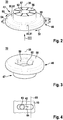
- Fig. 2 shows the holding head 33 for the in Fig. 1 shown holding device 31 of the rail foot holder 2 in a three-dimensional representation.
- the holding head 34 can be configured in accordance with the holding head 33.
- the holding head 33 has a hollow cylindrical spacer part 47 and a plate-shaped holding part 48.
- Fastening areas 49, 50 are configured on the holding part 48 of the holding head 33.
- the fastening areas 49, 50 are formed here on one side 51 of the holding part 48 of the holding head 33 which, in the assembled state, faces the contact plane 17. In a modified embodiment, only one fastening area 49 can be provided.
- the fastening area 49 extends in a direction of rotation 52 about the axis of rotation 35.
- the further fastening area 50 extends in a further direction of rotation 53 about the axis of rotation 35.
- the direction of rotation 52 and the further direction of rotation 53 are oriented relative to one another.
- the plate-shaped holding part 48 In an area 54 where the two fastening areas 49, 50 meet, the plate-shaped holding part 48 has a minimum thickness d. In an area 55, which lies opposite the area 54 with respect to the axis of rotation 35 and in which the fastening areas 49, 50 also meet, the plate-shaped holding part 48 has its maximum thickness D.
- the maximum thickness D results from the minimum thickness d plus one Slope s.
- the slope s results from a rotation in the direction of rotation 52 or the further direction of rotation 53 of 180 °.
- the holding head 33 is designed with a slope s opposite to the direction of rotation 52 or opposite to the further direction of rotation 53.
- the holding head 33 is initially oriented at least approximately with respect to its axis of rotation 35 such that the first side part 21 is located between the area 54 of the side 51 of the holding head 33 and the contact plane 17.
- the fitter can then rotate the holding head 33 about its axis of rotation 35, which reduces a holding dimension H, as can also be seen from FIG Fig. 5 is described.
- the Fitter set to no direction of rotation. That is to say, it can optionally achieve a fastening in the direction of rotation 52 or in the further direction of rotation 53.
- the holding head 33 has an end face 56 facing the contact plane 17 or the end face 17 ′ of the contact body 10.
- the end face 56 of the holding head 33 provided on the spacer 47 is urged against the contact body 10 in such a way that the holding head 33 is fixed against rotation about the axis of rotation 35 and, in this exemplary embodiment, against displacement along the second direction 42.
- the fastening force is here via the fastening means 37, 38 ( Fig. 1 ) applied.
- the end face 56 is designed as a structured end face 56.
- grooves 57 are formed on the end face 56 of the holding head 33 in this regard, of which only the groove 57 is identified to simplify the illustration.
- the groove 57 runs radially with respect to the axis of rotation 35 of the holding device 31.
- the end face 56 is otherwise designed such that the axis of rotation 35 is oriented perpendicular to the end face 56.
- Other structural elements, in particular depressions, can optionally also be configured in the end face 56.
- the grooves 57 are a possible design variant for depressions 57. Structuring the end face 56 has the advantage that dirt, liquids, such as oil, and the like have a reduced influence on the fixing of the holding head 33 on the contact body 10. In addition, the depressions 57 have the effect that the end face 56 digs into the contact plane 17 when the fastening means 37, 38 are tightened. The holding head 33 is thereby secured against rotation.
- Fig. 3 shows the in Fig. 2 shown holding head 33 from the viewing direction marked III.
- the plate-shaped holding part 48 has an end face 58 facing away from the contact plane 17 or the end face 17 ′ of the contact body 10.
- a receptacle 59 for a head 60 of the fastening means 37 extends from the end face 58.
- the receptacle 59 is not designed to be rotationally symmetrical with respect to the axis of rotation 35.
- the head 60 which is likewise not rotationally symmetrical, fits into the receptacle 59 in such a way that, in the assembled state, the holding head 33 and the fastening means 37 are rotationally fixed relative to one another.
- a depth of the receptacle 59 is less than a corresponding height of the head 61, 60 of the fastening means 37.
- the holding head 33 has an axial through-hole 62 through which a bolt (bolt section) 63 ( Fig. 4 ) of the fastening means 37 extends.
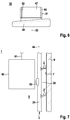
- FIG. 4 shows an excerpt, schematic representation of the contact body 10 and the bolt 63 of the first holding device 31 in an excerpt, sectional representation corresponding to a possible embodiment of the in FIG Fig. 1
- the rail foot holder 2 shown.
- the bolt 63 or bolt section 63 is guided in the second direction 42 in an elongated hole 64 of the contact body 10 so as to be movable.
- a broken line 65 illustrates a possible target position for a stop of the bolt 63 on the first side part 21 of the rail foot 20 in the assembled state. Since the line 65 shown interrupted intersects through the elongated hole 64, a certain tolerance compensation with regard to the design of the rail foot 20 is made possible.
- Fig. 5 shows in several diagrams a possible assembly sequence in which the in Fig. 1
- the rail foot holder 2 shown can be used to fasten the rail 3 in an elevator shaft, to explain a method according to an exemplary embodiment of the invention and to explain the mode of operation of the rail foot holder 2.
- the individual diagrams here show steps S1, S2, S3, S4, which occur during such an assembly can be carried out.
- step S1 the holding device 31 is first adjusted to the first side part 21 of the rail foot 20. This is also the one in the Fig. 4 line 65 shown in broken lines is illustrated in its position, the relevant stop 66 now being implemented on the first side part 21 by a side 66 ′ of the first side part 21.
- the holding device 31 strikes the stop 66 with its hollow cylindrical spacer part 47, then between the area 54 on the side 51 of the Holding part 48 and the contact plane 17 or the end face 17 'of the contact body 10 initially the maximum possible holding dimension H as the initial holding dimension H for the assembly.
- the holding dimension H between the area 54 and the contact plane 17 is preferably specified in such a way that a more or less large amount of play remains for the rail foot 20 with regard to all possible, production-related tolerances of the rail foot 20. This means that the desired backlash-free, but powerless fastening is only achieved in step S2.
- step S2 the mounting head 33 is rotated by the fitter in the first direction of rotation 52 or in the further direction of rotation 53. This is graphically illustrated by a hand 67 of the fitter.
- the holding dimension H. is reduced.
- the rotation in the direction of rotation 52 or the further direction of rotation 53 takes place until a backlash-free, but force-free fastening is achieved, as shown in step S3.
- this corresponds to a rotation of the holding head 33 in FIG Direction of rotation 52.
- the area 55 moves closer to the stop 66 or closer to the line 65 shown in broken lines.
- part of the available slope s has been used to reduce the holding dimension H to the desired value.
- step S4 the holding head 33 is then fixed relative to the contact body 10.
- the head 60 of the fastening means 37 is fixed by the fitter with a suitable tool 68 or with the hand 67.
- a nut 69 ( Fig. 8 ) of the holding device 38 are tightened.
- the rail foot holder 2 According to the exemplary embodiment, an adjustment, in particular an adjustment of the holding dimension H, with respect to the rail foot 20 is possible without dismantling.
- the rail foot 20 can be fastened in the elevator shaft 8 by means of the rail foot holder 2 without dismantling.
- the rail foot holder 2 can already be correspondingly preassembled upon delivery, so that in particular the holding devices 31, 32 are already in the preassembled state on the contact body 10. It is then not necessary to dismantle the holding devices 31, 32 for setting and / or fastening.
- Another holding dimension H ' can be adjusted in a corresponding manner on the holding head 34 of the second holding device 32.
- FIG Fig. 1 the further holding dimension H 'in relation to the second side part 22 of the rail foot 20 is shown in FIG Fig. 1 illustrated.
- this does not exclude the possibility that the rail foot holder 2 can only be assembled during assembly, that is, after delivery to the assembly site.
- step S3 and the fastening in step S4 there are contacts 75, 76 between the rail foot 20 and the holding head 33 of the first holding device 31.
- the contact 75 is here between the first side part 21 in the area of its stop 66 or its side 66 ' and the hollow cylinder-shaped spacer part 47.
- the contact 76 results between the fastening area 50 or the fastening area 49 and an upper side 27 of the rail foot 20 which faces away from its lower side 23.
- a sliding surface 77 is preferably provided on the hollow cylindrical spacer part 47 in order to avoid static friction on the contact 75 when the rail foot 20 is displaced relative to the building, in particular the wall 9.
- a suitable lubricant can be attached to the sliding surface 77.
- the fastening areas 49, 50 are preferably made as smooth as possible.
- the sliding surface 77 and / or the fastening areas 49, 50 are formed on or with a friction-reducing coating.
- Fig. 6 shows the in Fig. 2 shown holding head 33 according to a further embodiment.
- a sliding ring 80 is mounted on the hollow cylindrical spacer part 47 of the holding head 33.
- Contact 75 ( Fig. 5 ) then comes about between an outer side 81 of the sliding ring 80 and the side 66 'of the first side part 21 of the rail foot 20.
- the sliding ring 80 can rotate about the axis of rotation 35 relative to the holding head 33.
- the bearing 82 of the sliding ring 80 designed here as a sliding bearing 82 on the hollow cylindrical spacer 47, can be lubricated by a suitable lubricant.
- Fig. 7 shows the elevator installation 1, in which the rail 3 with the in Fig. 1 shown rail foot holder 2 and a further rail foot holder 2 'in the elevator shaft 8 is attached, in an excerpt, schematic representation.
- the elevator installation 1 here has an elevator cage 90 which is suspended from a suspension element 91.
- a guide roller 92 is shown by way of example, by means of which the elevator car 90 is guided on the rail 3.
- the guide roller 92 interacts with the rail head 24 of the rail 3. Managers act essentially in or against the second direction 42.
- the rail 3 is reliably fixed via the holding heads 33, 34.
- the rail 3 is also held reliably on the wall 9 or the wall 7 of the elevator shaft 8.
- Fig. 8 shows the in Fig. 1 shown rail foot holder 2 and the rail 3 in an excerpt from the viewing direction designated VIII.
- the nut 70 for the bolt 71, in particular screw bolt 71, of the second holding device 32 is shown here.
- the screw bolt 71 here has the head 61.
- the nut 70 is in step S4 ( Fig. 5 ) tightened while the head 61 and thus the holding head 34 is held in its position.
- Another nut 69 which is designed like the nut 70, is used for the bolt 63, in particular screw bolt 63, only one nut 69, 70 being shown by way of example to simplify the illustration. Further elements can be used here, in particular a washer 72.
Landscapes
- Lift-Guide Devices, And Elevator Ropes And Cables (AREA)
- Chairs For Special Purposes, Such As Reclining Chairs (AREA)
Description
Die Erfindung betrifft einen Schienenfußhalter zum Befestigen einer Schiene einer Aufzugsanlage in einem Aufzugsschacht und ein Verfahren zum Befestigen einer Schiene einer Aufzugsanlage in einem Aufzugsschacht mittels vorzugsweise mehreren solchen SchienenfußhalternThe invention relates to a rail foot holder for fastening a rail of an elevator installation in an elevator shaft and a method for fastening a rail of an elevator installation in an elevator shaft by means of preferably several such rail foot holders
Aus der
Bei der Montage einer Aufzugsanlage in einem Aufzugsschacht eines Gebäudes können die Aufzugsschienen (Schienen) direkt oder mittelbar an einer Gebäudewand befestigt werden. Solch eine Aufzugsschiene kann beispielsweise als eine Führungsschiene für eine Aufzugskabine oder ein Gegengewicht der Aufzugsanlage dienen. Solche Aufzugsschienen erstrecken sich in der Regel über die gesamte Fahrstrecke des Aufzugs, was vielfach annähernd der Höhe des Gebäudes entsprechen kann. Die Aufzugsschienen sind hierbei so stark im Gebäude befestigt, dass seitliche Führungskräfte sicher aufgenommen werden können. Allerdings kann sich die Gebäudehöhe im Zeitverlauf verändern. Hierfür kommen mehrere Ursachen in Frage. Beispielsweise kann ein Gebäude nach seiner Fertigstellung in Folge einer Austrocknung von Beton und durch eine Gebäudesetzung schrumpfen. Auch durch Temperaturänderungen und durch Sonneneinstrahlung können Veränderungen der Gebäudehöhe bewirkt werden.When installing an elevator system in an elevator shaft of a building, the elevator rails (rails) can be attached directly or indirectly to a building wall. Such an elevator rail can serve, for example, as a guide rail for an elevator car or a counterweight of the elevator installation. Such elevator rails usually extend over the entire travel path of the elevator, which in many cases can approximately correspond to the height of the building. The elevator rails are so firmly attached in the building that lateral managers can be safely picked up. However, the building height can change over time. There are several possible reasons for this. For example, a building can shrink after its completion as a result of concrete drying out and building settlement. Changes in building height can also be caused by temperature changes and solar radiation.
Höhenänderungen des Gebäudes wirken sich in der Regel in nicht kompensierten relativen Längenänderungen zu den metallischen Aufzugsschienen aus. Dies bedeutet, dass sich die Führungsschienen somit im Aufzugsschacht gegenüber dem Gebäude verschieben. Schrumpft beispielsweise das Gebäude, dann wachsen die Führungsschienen in Relation zum Gebäude. Um bei solchen relativen Längenänderungen Deformationen in Schienenabschnitten zwischen Befestigungspunkten zu vermeiden, müssen die Befestigungspunkte für eine Schiene, insbesondere Führungsschiene, so ausgeführt sein, dass ein Längenausgleich ermöglicht ist. Gleichzeitig muss aber auch eine den jeweiligen Anforderungen genügende Befestigung der Schiene sichergestellt sein, so dass beispielsweise im Fall einer Führungsschiene die Führungskräfte aufgenommen werden können.Changes in the height of the building usually result in uncompensated changes in length relative to the metal elevator rails. This means that the guide rails move in the elevator shaft in relation to the building. For example, if the building shrinks, the guide rails grow in relation to the building. In order to deformations in To avoid rail sections between fastening points, the fastening points for a rail, in particular a guide rail, must be designed in such a way that length compensation is possible. At the same time, however, it must also be ensured that the rail is fastened in such a way that it meets the respective requirements, so that, for example in the case of a guide rail, the managers can be accommodated.
Aufgabe der Erfindung ist es, einen Schienenfußhalter, der zum Befestigen einer Schiene einer Aufzugsanlage in einem Aufzugsschacht dient, und ein Verfahren zum Befestigen einer Schiene einer Aufzugsanlage in einem Aufzugsschacht mittels zumindest einem Schienenfußhalter anzugeben, die verbessert ausgestaltet sind. Speziell kann sich hierbei die Aufgabe der Erfindung stellen, einen solchen Schienenfußhalter und ein solches Verfahren anzugeben, die eine verbesserte Befestigung ermöglichen, bei der insbesondere eine vereinfachte Einstellung und Montage ermöglicht wird, wobei im montierten Zustand sowohl eine relative Verschiebung der Schiene entlang ihrer Erstreckung ermöglicht als auch eine Bewegung oder Verdrehung quer beziehungsweise um ihre Erstreckung verhindert ist.The object of the invention is to provide a rail foot holder, which is used to fasten a rail of an elevator system in an elevator shaft, and a method for securing a rail of an elevator system in an elevator shaft by means of at least one rail foot holder, which have an improved design. In particular, the object of the invention can be to provide such a rail foot holder and such a method which enable improved fastening, in which in particular simplified adjustment and assembly is made possible, with both a relative displacement of the rail along its extension in the assembled state as well as movement or rotation across or around its extent is prevented.
Im Folgenden sind Lösungen und Vorschläge für eine entsprechende Ausgestaltung angegeben, die einen Schienenfußhalter und ein Verfahren, das mit zumindest einem Schienenfußhalter durchgeführt wird, betrifft und zumindest Teile der gestellten Aufgabe löst. Des weiteren sind vorteilhafte ergänzende oder alternative Weiterbildungen und Ausgestaltungen angegeben oder beschrieben.Solutions and proposals for a corresponding embodiment are given below, which concern a rail foot holder and a method that is carried out with at least one rail foot holder and which solves at least parts of the problem. Furthermore, advantageous additional or alternative developments and configurations are given or described.
Bei einer Lösung kann ein Schienenfußhalter, der zum Befestigen einer Schiene in einem Aufzugsschacht dient, mit einem Anlagekörper, der in dem Aufzugsschacht anordenbar ist, und zumindest einer Halteeinrichtung ausgebildet sein, wobei durch den Anlagekörper eine Anlageebene für einen Schienenfuß der Schiene vorgegeben ist, wobei die Halteeinrichtung einen Haltekopf aufweist, wobei zum Befestigen der Schiene ein erstes Seitenteil des Schienenfußes zwischen dem Haltekopf der Halteeinrichtung und der Anlageebene anordenbar ist, wobei beim Befestigen der Schiene ein Haltemaß zwischen dem Haltekopf der Halteeinrichtung und der Anlageebene zum Ausgleich von Toleranzen des ersten Seitenteils des Schienenfußes veränderbar, wobei der Haltekopf der Halteeinrichtung zum Verringern des Haltemaßes in einer Drehrichtung um eine Drehachse der Halteeinrichtung in eine Befestigungsstellung drehbar ist und wobei eine der Anlageebene zugewandte Seite des Haltekopfes der Halteeinrichtung in zumindest einem sich in der Drehrichtung um die Drehachse der Halteeinrichtung erstreckenden Befestigungsbereich, an dem ein zumindest mittelbarer Kontakt zwischen dem Haltekopf der Halteeinrichtung und dem ersten Seitenteil des Schienenfußes ermöglicht ist, mit einer Steigung entgegen der Drehrichtung ausgestaltet ist.In one solution, a rail foot holder, which is used to fasten a rail in an elevator shaft, can be designed with a contact body that can be arranged in the elevator shaft and at least one holding device, the contact body providing a contact plane for a rail foot of the rail, with the holding device has a holding head, wherein a first side part of the rail foot can be arranged between the holding head of the holding device and the contact plane for fastening the rail, wherein a holding dimension between the holding head of the holding device and the contact plane to compensate for tolerances of the first side part of the Rail foot changeable, wherein the holding head of the holding device can be rotated in a direction of rotation about an axis of rotation of the holding device in a fastening position to reduce the holding dimension and wherein a side of the holding head of the holding device facing the contact plane in at least a fastening area extending in the direction of rotation around the axis of rotation of the holding device, on which an at least indirect contact between the holding head of the holding device and the first side part of the rail foot is made possible, is designed with a slope opposite to the direction of rotation.
Die Schiene (Aufzugsschiene) ist hierbei kein Bestandteil des Schienenfußhalters. Insbesondere kann der Schienenfußhalter auch unabhängig von einer Schiene oder anderen Komponenten einer Aufzugsanlage hergestellt und vertrieben werden. Der Schienenfußhalter ist so ausgestaltet, dass in Bezug auf eine bestimmte Anordnung der Schiene eine verbesserte Anordnung und/oder Montage der Schiene ermöglicht ist. Insbesondere kann hierbei beim Montieren der Aufzugsanlage, bei der ein oder mehrere Schienen über vorzugsweise jeweils mehrere Schienenfußhalter in dem Aufzugsschacht befestigt werden, eine verbesserte Einstellung in Bezug auf eine beispielsweise spielfreie Befestigung der Schiene erfolgen. Dies ermöglicht insbesondere einen Ausgleich von Fertigungstoleranzen der Schiene, die speziell eine Materialstärke eines Schienenfußes betreffen können. Beispielsweise kann die Materialstärke des Schienenfußes von Schienenabschnitt zu Schienenabschnitt schwanken. Wenn solche Schienenabschnitte dann aneinandergefügt werden, um die Schiene zu bilden, dann wird in jedem Abschnitt gegebenenfalls eine etwas andere Einstellung des Haltemaßes erforderlich sein. Diese Einstellung kann auf besonders einfache Weise durch einen Monteur erfolgen, wenn die Schiene im Aufzugsschacht montiert wird.The rail (elevator rail) is not part of the rail foot holder. In particular, the rail foot holder can also be manufactured and sold independently of a rail or other components of an elevator system. The rail foot holder is designed in such a way that an improved arrangement and / or assembly of the rail is made possible with regard to a specific arrangement of the rail. In particular, when assembling the elevator system, in which one or more rails are fastened in the elevator shaft via preferably several rail foot holders, an improved setting can take place with regard to fastening the rail without play, for example. This makes it possible in particular to compensate for manufacturing tolerances of the rail, which can specifically affect a material thickness of a rail foot. For example, the material thickness of the rail foot can vary from rail section to rail section. If such rail sections are then joined together to form the rail, then a slightly different adjustment of the holding dimension may be required in each section. This setting can be carried out in a particularly simple manner by a fitter when the rail is installed in the elevator shaft.
Bei einer weiteren Lösung kann ein Verfahren zum Befestigen einer Schiene einer Aufzugsanlage in einem Aufzugsschacht mittels zumindest einem erfindungsgemäßen Schienenfußhalter angegeben werden, wobei der Anlagekörper ortsfest in dem Aufzugsschacht angeordnet wird, wobei ein erstes Seitenteil des Schienenfußes zwischen dem Haltekopf der Halteeinrichtung und der durch den Anlagekörper vorgegebenen Anlageebene angeordnet wird, und wobei der Haltekopf zum Verringern des Haltemaßes zwischen dem Haltekopf der Halteeinrichtung und der Anlageebene um die Drehachse der Halteeinrichtung gedreht wird.In a further solution, a method for fastening a rail of an elevator system in an elevator shaft by means of at least one rail foot holder according to the invention can be specified, the contact body being arranged in a stationary manner in the elevator shaft, with a first side part of the rail foot between the holding head of the holding device and that through the contact body predetermined contact plane is arranged, and wherein the holding head is rotated to reduce the holding dimension between the holding head of the holding device and the contact plane about the axis of rotation of the holding device.
Es versteht sich, dass die Bezeichnungen erstes Seitenteil und zweites Seitenteil des Schienenfußes hier zur Bezeichnung der beiden Seitenteile des Schienenfußes gemacht sind, ohne dass hierdurch eine Festlegung erfolgen soll, welches der beiden Seitenteile als erstes beziehungsweise als zweites Seitenteil bezeichnet wird. Speziell kann der Schienenfuß so abgewandelt ausgestaltet sein, dass die beiden Seitenteile des Schienenfußes gerade in vertauschter Weise als erstes und zweites Seitenteil bezeichnet sind. Konstruktiv kann dies einer Spiegelung des Schienenfußhalters an einer geeigneten Konstruktionsebene entsprechen. Prinzipiell sind allerdings auch diesbezüglich spiegelsymmetrische Ausführungen des Schienenfußhalters denkbar. Entsprechendes gilt für die Bezeichnungen Halteeinrichtung und weitere Halteeinrichtung beziehungsweise erste und zweite Halteeinrichtung.It goes without saying that the designations first side part and second side part of the rail foot are used here to denote the two side parts of the rail foot, without this being intended to specify which of the two side parts is designated as the first or second side part. Specifically, the rail foot can be modified so that the two side parts of the Rail foot are just referred to in an interchanged manner as the first and second side part. In terms of design, this can correspond to a reflection of the rail foot holder on a suitable construction plane. In principle, however, mirror-symmetrical designs of the rail foot holder are also conceivable in this regard. The same applies to the terms holding device and further holding device or first and second holding device.
Ein besonderes Merkmal der vorgeschlagenen Ausgestaltung besteht darin, dass ein Einstellen des Haltekopfes der Halteeinrichtung an die in der Regel toleranzbehafteten Abmessungen des Schienenfußes ohne Zerlegen der Halteeinrichtung ermöglicht ist, was im Rahmen dieser Anmeldung als "Einstellen ohne Zerlegen" bezeichnet ist. Entsprechend ist ein "Befestigen ohne Zerlegen" möglich, indem bei einer möglichen Weiterbildung ein Zustellen beziehungsweise Annähern der Halteeinrichtung an den Schienenfuß möglich ist, was beispielsweise durch ein geeignetes Langloch realisiert werden kann. Des weiteren kann in vorteilhafter Weise eine Ausgestaltung realisiert werden, bei der sowohl bezüglich dem Einstellen ohne Zerlegen als auch bezüglich dem Befestigen ohne Zerlegen eine Arretierung beziehungsweise Fixierung des Haltekopfes in der gewünschten Stellung durch einen einzigen Montageschritt, der beispielsweise im Festziehen einer Schraube besteht, ermöglicht ist. Mögliche Ausführungen für das Einstellen ohne Zerlegen sowie das Befestigen ohne Zerlegen sind auch nachfolgend und anhand der Beschreibung der Figuren im weiteren Detail erläutert.A special feature of the proposed embodiment is that the holding head of the holding device can be adjusted to the generally toleranced dimensions of the rail foot without dismantling the holding device, which is referred to in the context of this application as "setting without disassembling". Correspondingly, "fastening without dismantling" is possible in that, in a possible further development, the holding device can be infeed or brought closer to the rail foot, which can be achieved, for example, by a suitable elongated hole. Furthermore, an embodiment can be implemented in an advantageous manner in which both the setting without dismantling and the fastening without dismantling allow the holding head to be locked or fixed in the desired position by a single assembly step, for example tightening a screw is. Possible designs for setting without dismantling and for fastening without dismantling are also explained in further detail below and with reference to the description of the figures.
Vorteilhaft ist es somit, dass der Haltekopf der Halteeinrichtung für ein zum Verringern des Haltemaßes dienendes Einstellen in der Drehrichtung um die Drehachse der Halteeinrichtung in die Befestigungsstellung drehbar ist. Ferner ist es vorteilhaft, dass der Haltekopf der Halteeinrichtung bei dem zum Verringern des Haltemaßes dienenden Einstellen in der Drehrichtung um die Drehachse der Halteeinrichtung in die Befestigungsstellung gedreht wird. Hierbei ist ein Einstellen ohne Zerlegen möglich.It is therefore advantageous that the holding head of the holding device can be rotated into the fastening position in the direction of rotation about the axis of rotation of the holding device for an adjustment serving to reduce the holding dimension. Furthermore, it is advantageous that the holding head of the holding device is rotated in the direction of rotation about the axis of rotation of the holding device into the fastening position during the setting, which serves to reduce the holding dimension. It can be adjusted without dismantling.
Ferner ist zum Befestigen der Schienen beziehungsweise beim Befestigen der Schiene ein Befestigen ohne Zerlegen möglich.Furthermore, for fastening the rails or when fastening the rail, fastening without dismantling is possible.
Vorteilhaft ist es ferner, dass der Haltekopf bei einem zum Verringern des Haltemaßes dienenden Einstellen, insbesondere bei einem Einstellen ohne Zerlegen, in einer entgegen der Drehrichtung orientierten weiteren Drehrichtung um die Drehachse in eine Befestigungsstellung drehbar ist und dass die der Anlageebene zugewandte Seite des Haltekopfes in einem sich in der weiteren Drehrichtung um die Drehachse erstreckenden weiteren Befestigungsbereich, an dem ein zumindest mittelbarer Kontakt zwischen dem Haltekopf und dem ersten Seitenteil des Schienenfußes ermöglicht ist, mit einer Steigung entgegen der weiteren Drehrichtung ausgestaltet ist. Hierdurch kann der Monteur beim Einstellen das Haltemaß unabhängig davon verringern, ob er zum Einstellen den Haltekopf in der Drehrichtung oder in der anderen, nämlich weiteren, Drehrichtung dreht. Hierdurch ergeben sich auch ergonomische Vorteile, da sowohl für die rechte als auch für die linke Hand die ergonomisch günstigste Drehrichtung von dem Monteur gewählt werden kann. Der Haltekopf kann diesbezüglich in seiner Größe und Ausgestaltung, insbesondere an seiner der Anlageebene abgewandten Seite, so ausgestaltet werden, dass beispielsweise ein vorteilhaftes Greifen mit einem Handschuh ermöglicht ist.It is also advantageous that the holding head can be rotated about the axis of rotation into a fastening position in a further direction of rotation oriented counter to the direction of rotation in a setting serving to reduce the holding dimension, in particular when setting without dismantling, and that the side of the Holding head in a further fastening area extending in the further direction of rotation around the axis of rotation, where an at least indirect contact between the holding head and the first side part of the rail foot is made possible, is designed with a slope opposite to the further direction of rotation. As a result, the fitter can reduce the holding measure when making adjustments, regardless of whether he is turning the holding head in the direction of rotation or in the other, namely further, direction of rotation for the purpose of adjustment. This also results in ergonomic advantages, since the fitter can choose the most ergonomically favorable direction of rotation for both the right and the left hand. In this regard, the size and configuration of the holding head, in particular on its side facing away from the contact plane, can be designed in such a way that, for example, advantageous gripping with a glove is made possible.
Vorteilhaft ist es, dass die Halteeinrichtung relativ zu dem Grundkörper so verstellbar ist, dass ein Abstand zwischen der Drehachse der Halteeinrichtung und einer weiteren Halteeinrichtung, zwischen denen der Schienenfuß befestigbar ist, veränderbar ist. Bei einer Montage kann vor einem Verringern des Abstands zwischen der Drehachse der Halteeinrichtung und der weiteren Halteeinrichtung die Schiene mit ihrem Schienenfuß zwischen den beiden Halteeinrichtungen positioniert werden, dann die Halteeinrichtung relativ zu dem Grundkörper so verstellt werden, dass der Abstand zwischen der Drehachse der Halteeinrichtung und der weiteren Halteeinrichtung verringert wird, bis die gewünschte Befestigungsposition für die Drehachse erreicht ist, und anschließend der Haltekopf um die Drehachse gedreht werden, bis das geeignete Haltemaß eingestellt ist. Hierdurch ist eine Befestigung der Schiene mittels der Halteeinrichtung ohne Zerlegen möglich. Bei einer möglichen Ausgestaltung ist es vorteilhaft, dass der Anlagekörper hierfür ein Langloch aufweist, in dem ein Bolzen der Halteeinrichtung geführt ist. Diese Ausgestaltung ermöglicht dann eine Verstellung der Halteeinrichtung relativ zu dem Anlagekörper.It is advantageous that the holding device can be adjusted relative to the base body in such a way that a distance between the axis of rotation of the holding device and a further holding device, between which the rail foot can be fastened, can be changed. During assembly, before the distance between the axis of rotation of the holding device and the further holding device is reduced, the rail with its rail foot can be positioned between the two holding devices, then the holding device can be adjusted relative to the base body so that the distance between the axis of rotation of the holding device and the further holding device is reduced until the desired fastening position for the axis of rotation is reached, and then the holding head is rotated about the axis of rotation until the appropriate holding dimension is set. This enables the rail to be fastened by means of the holding device without dismantling. In a possible embodiment, it is advantageous that the contact body has an elongated hole for this purpose, in which a bolt of the holding device is guided. This configuration then enables the holding device to be adjusted relative to the contact body.
Vorteilhaft ist es, dass der Haltekopf der Halteeinrichtung eine dem Anlagekörper zugewandte Stirnseite aufweist, die zum Fixieren des Haltekopfes relativ zu dem Anlagekörper mittels eines Befestigungsmittels der Halteeinrichtung gegen den Anlagekörper beaufschlagbar ist. Solch ein Befestigungsmittel kann beispielsweise einen Schraubenbolzen aufweisen, der zum Beispiels mittels einer Mutter und einer Beilagscheibe an dem Anlagekörper befestigt wird. Hierdurch ergibt sich die Möglichkeit, dass der Schraubenbolzen zugleich als Bolzen dient, der beispielsweise in einem Langloch des Anlagekörpers geführt ist, um eine Verstellung der Halteeinrichtung relativ zu dem Anlagekörper zu ermöglichen.It is advantageous that the holding head of the holding device has an end face which faces the contact body and can be acted upon against the contact body by means of a fastening means of the holding device in order to fix the holding head relative to the contact body. Such a fastening means can, for example, have a screw bolt which is fastened to the contact body, for example by means of a nut and a washer. This results in the possibility that the screw bolt also serves as a bolt which is guided, for example, in an elongated hole in the contact body, in order to adjust the holding device allow relative to the plant body.
Hierbei ist es des weiteren von Vorteil, dass die dem Anlagekörper zugewandte Stirnseite des Haltekopfes der Halteeinrichtung als strukturierte Stirnseite ausgestaltet ist. Die strukturierte Stirnseite kann die Funktion einer Fixierung unterstützen, da der Einfluss von Schmutz, Flüssigkeiten, wie Öl, und dergleichen verringert wird. Beispielsweise besteht die Möglichkeit, in der dem Anlagekörper zugewandten Stirnseite des Haltekopfes Rillen vorzusehen. Hierbei ist es besonders vorteilhaft, wenn solche Rillen als sich radial zu der Drehachse der Halteeinrichtung verlaufende Rillen in der dem Anlagekörper zugewandten Stirnseite des Haltekopfes ausgestaltet sind. Hierbei ist auch eine Kombination von solchen Maßnahmen denkbar. Beispielsweise können Rillen, insbesondere radial zu der Drehachse verlaufende Rillen, auch mit anderen Strukturelementen an der Stirnseite kombiniert werden, um eine strukturierte Stirnseite zu bilden. Die strukturierte Stirnseite ist vorzugsweise so ausgestaltet, dass sich die Stirnseite des Haltekopfes beim Fixieren beziehungsweise Festschrauben mit dem Anlagekörper verkrallt. Dadurch wird einem unbeabsichtigten Verdrehen des Haltekopfs im montierten Zustand vorgebeugt. Diese radial zu der Drehachse der Halteeinrichtung verlaufenden Rillen, die zur Ausgestaltung der strukturierten Stirnseite dienen können, erfüllen dieses Kriterium.It is also advantageous here that the face of the holding head of the holding device facing the contact body is designed as a structured face. The structured end face can support the function of a fixation, since the influence of dirt, liquids, such as oil, and the like is reduced. For example, there is the possibility of providing grooves in the end face of the holding head facing the contact body. It is particularly advantageous here if such grooves are designed as grooves extending radially to the axis of rotation of the holding device in the end face of the holding head facing the contact body. A combination of such measures is also conceivable here. For example, grooves, in particular grooves running radially to the axis of rotation, can also be combined with other structural elements on the end face in order to form a structured end face. The structured end face is preferably designed in such a way that the end face of the holding head claws with the contact body when it is fixed or screwed tight. This prevents unintentional twisting of the holding head in the assembled state. These grooves, which run radially to the axis of rotation of the holding device and can serve to design the structured end face, meet this criterion.
Des weiteren ist es vorteilhaft, dass eine weitere Halteeinrichtung vorgesehen ist und dass eine weitere Halteeinrichtung beziehungsweise eine Drehachse der weiteren Halteeinrichtung ortsfest an dem Anlagekörper angeordnet ist. Bei dieser Ausgestaltung kann es insbesondere möglich sein, dass nur die Halteeinrichtung so gegenüber dem Anlagekörper verstellbar ist, dass sich die Drehachse der Halteeinrichtung relativ zu dem Anlagekörper verstellen lässt. Sofern eine Positionierung der weiteren Halteeinrichtung relativ zu der Schiene erforderlich ist, kann dies in vorteilhafter Weise durch eine Verstellung des Anlagekörpers gegenüber einem Befestigungskörper erreicht werden. Bei der Montage wird dann zunächst die weitere Halteeinrichtung in die gewünschte Position im Aufzugsschacht gebracht. Dann kann der Anlagekörper in seiner Position fixiert werden, was beispielsweise durch eine entsprechende Befestigung an dem Befestigungskörper ermöglicht ist. Anschließend kann die Halteeinrichtung relativ zu der weiteren Halteeinrichtung verstellt werden. Im letzten Schritt können dann ein Haltekopf der Halteeinrichtung und ein Haltekopf der weiteren Halteeinrichtung eingestellt werden.Furthermore, it is advantageous that a further holding device is provided and that a further holding device or an axis of rotation of the further holding device is arranged in a stationary manner on the contact body. In this embodiment, it may in particular be possible that only the holding device is adjustable relative to the contact body in such a way that the axis of rotation of the holding device can be adjusted relative to the contact body. If the further holding device needs to be positioned relative to the rail, this can be achieved in an advantageous manner by adjusting the contact body relative to a fastening body. During assembly, the further holding device is then first brought into the desired position in the elevator shaft. The contact body can then be fixed in its position, which is made possible, for example, by a corresponding attachment to the attachment body. The holding device can then be adjusted relative to the further holding device. In the last step, a holding head of the holding device and a holding head of the further holding device can then be adjusted.
Somit ist es ebenfalls von Vorteil, wenn eine weitere Halteeinrichtung vorgesehen ist, die einen Haltekopf aufweist, wobei zum Befestigen der Schiene ein zweites Seitenteil des Schienenfußes zwischen dem Haltekopf der weiteren Halteeinrichtung und der Anlagenebene anordenbar ist, wobei beim Befestigen der Schiene ein weiteres Haltemaß zwischen dem Haltekopf der weiteren Halteeinrichtung und der Anlageebene zum Ausgleich von Toleranzen des zweiten Seitenteils des Schienenfußes veränderbar ist, wobei der Haltekopf der weiteren Halteeinrichtung bei einem zum Verringern des weiteren Haltemaßes dienenden Einstellen in einer Drehrichtung um eine Drehachse der weiteren Halteeinrichtung in eine Befestigungsstellung drehbar ist und wobei eine der Anlageebene zugewandte Seite des Haltekopfes der weiteren Halteeinrichtung in zumindest einem sich in der Drehrichtung um die Drehachse der Halteeinrichtung erstreckenden Befestigungsbereich, an dem ein zumindest mittelbarer Kontakt zwischen dem Haltekopf der weiteren Halteeinrichtung und dem zweiten Seitenteil des Schienenfußes ermöglicht ist, mit einer Steigung entgegen der Drehrichtung ausgestaltet ist. Diese Ausgestaltung ermöglicht beispielsweise Montageschritte, nach denen der Schienenfuß beidseitig zumindest im Wesentlichen spielfrei befestigt ist. Hierbei ist es auch denkbar, dass sich das Haltemaß und das weitere Haltemaß unterscheiden, sofern dies im jeweiligen Anwendungsfall, insbesondere aufgrund unterschiedlicher Toleranzen an dem Schienenfuß, erforderlich ist.Thus, it is also advantageous if a further holding device is provided which has a holding head, wherein a second side part of the rail foot can be arranged between the holding head of the further holding device and the system level for fastening the rail, with a further holding dimension between the holding head of the further holding device and the contact level to compensate for tolerances of the second side part when fastening the rail of the rail foot can be changed, the holding head of the further holding device being rotatable in a direction of rotation about an axis of rotation of the further holding device into a fastening position when the further holding device is adjusted to reduce the further holding device, and one side of the holding head of the further holding device facing the contact plane in at least one in the direction of rotation about the axis of rotation of the holding device extending fastening area, at which an at least indirect contact between the holding head of the further holding device and the second side part of the rail foot is enabled i st, is designed with a slope opposite to the direction of rotation. This configuration enables, for example, assembly steps according to which the rail foot is fastened on both sides at least essentially without play. It is also conceivable here that the holding dimension and the further holding dimension differ if this is necessary in the respective application, in particular due to different tolerances on the rail foot.
Vorteilhaft ist es, dass der Haltekopf der Halteeinrichtung beziehungsweise der Haltekopf der weiteren Halteeinrichtung an der der Anlageebene zugewandten Seite in dem zumindest einen Befestigungsbereich mit einer sich in der Drehrichtung beziehungsweise in der weiteren Drehrichtung kontinuierlichen Steigung ausgestaltet ist. Die Steigung erfährt dadurch keine sprunghafte Änderung. Diese Ausgestaltung kann sich somit auf den Haltekopf der Halteeinrichtung und/oder den Haltekopf der weiteren Halteeinrichtung beziehen. Ferner kann sich dies in Bezug auf den Haltekopf der Halteeinrichtung oder den Haltekopf der weiteren Halteeinrichtung auf nur einen beziehungsweise nur den einzigen Befestigungsbereich oder, sofern zwei Befestigungsbereiche vorgesehen sind, auf beide Befestigungsbereiche beziehen. Eine bevorzugte Ausgestaltung der sich nicht sprunghaft ändernden Steigung besteht in einer kontinuierlich verlaufenden Steigung. Hierbei sind unterschiedliche Ausgestaltungen denkbar.It is advantageous that the holding head of the holding device or the holding head of the further holding device is designed on the side facing the contact plane in the at least one fastening area with a continuous slope in the direction of rotation or in the further direction of rotation. The gradient does not experience any sudden change. This configuration can thus relate to the holding head of the holding device and / or the holding head of the further holding device. Furthermore, in relation to the holding head of the holding device or the holding head of the further holding device, this can refer to only one or only the single fastening area or, if two fastening areas are provided, to both fastening areas. A preferred embodiment of the incline, which does not change abruptly, consists in a continuously running incline. Different configurations are conceivable here.
Beispielsweise kann die Steigung so ausgestaltet sein, dass sich das Haltemaß beim Drehen in der Drehrichtung beziehungsweise in der weiteren Drehrichtung linear mit dem Drehwinkel verändert.For example, the slope can be designed in such a way that the holding dimension changes linearly with the angle of rotation when rotating in the direction of rotation or in the further direction of rotation.
Des weiteren ist es vorteilhaft, dass ein Befestigungskörper vorgesehen ist, der ortsfest im Aufzugsschacht befestigbar ist, und dass der Anlagekörper mit dem Befestigungskörper verbindbar ist. Hierbei ist es des weiteren vorteilhaft, wenn der Anlagekörper in mehreren möglichen Verbindungspositionen mit dem Befestigungskörper verbindbar ist. Hierbei können diskrete und/oder kontinuierliche Verstellmöglichkeiten realisiert werden. Dies ermöglicht dann nach der ortsfesten Befestigung des Befestigungskörpers eine vorteilhafte Anpassung der Lage des Anlagekörpers an die zur Befestigung der Schiene vorgegebene Sollposition.Furthermore, it is advantageous that a fastening body is provided which can be fastened in a stationary manner in the elevator shaft, and that the contact body can be connected to the fastening body. It is also advantageous here if the contact body can be connected to the fastening body in several possible connection positions. Discrete and / or continuous adjustment options can be implemented here. After the fastening body has been fixed in place, this then enables the position of the contact body to be advantageously adapted to the desired position specified for fastening the rail.
Vorteilhaft ist es auch, dass an dem Haltekopf beziehungsweise dem weiteren Haltekopf eine zylindermantelförmige Gleitfläche vorgesehen ist, an der zur Führung des Schienenfußes ein Kontakt zwischen dem ersten Seitenteil beziehungsweise dem zweiten Seitenteil des Schienenfußes und dem Haltekopf ermöglicht ist, wenn die Schiene befestigt ist. Kommt es beispielsweise zu relativen Längenänderungen zwischen der Schiene und dem Gebäude, dann wird ein Längsausgleich entlang der Erstreckung der Schiene erforderlich, die hierbei von dem Schienenfußhalter gehalten wird. Gleichzeitig soll die Schiene allerdings auch entlang ihrer Erstreckung relativ zu dem Schienenhalter bewegbar bleiben. Speziell ist es hierbei sinnvoll, dass ein Aufbau von mechanischen Spannungen entlang der Erstreckung einer Schiene vermieden wird. Neben einer über das Haltemaß beziehungsweise das weitere Haltemaß realisierten, im Wesentlichen spielfreien, aber praktisch kraftlosen Befestigung wird dies durch das Reduzieren einer Haltreibung zwischen dem Haltekopf und der Schiene ermöglicht.It is also advantageous that a cylinder jacket-shaped sliding surface is provided on the holding head or the further holding head, on which contact between the first side part or the second side part of the rail foot and the holding head is enabled for guiding the rail foot when the rail is attached. If, for example, there are relative changes in length between the rail and the building, a longitudinal compensation along the extent of the rail is required, which is held by the rail foot holder. At the same time, however, the rail should also remain movable relative to the rail holder along its extent. In particular, it makes sense here to avoid the build-up of mechanical stresses along the extension of a rail. In addition to an essentially play-free, but practically powerless fastening implemented via the holding dimension or the further holding dimension, this is made possible by reducing the holding friction between the holding head and the rail.
Vorteilhaft ist es deshalb auch, dass die Gleichfläche an einer reibungsreduzierten Beschichtung des Haltekopfes beziehungsweise des weiteren Haltekopfes ausgebildet ist, die unter anderen die diesbezügliche Haftreibung verringert. Bei einer abgewandelten Ausgestaltung ist es entsprechend vorteilhaft, dass an der Gleitfläche des Haltekopfes beziehungsweise des weiteren Haltekopfes ein zumindest näherungsweise hohlzylinderförmiger Gleitring gelagert ist. Hierbei kann zur Führung des Schienenfußes dann ein Kontakt zwischen dem ersten Seitenteil beziehungsweise dem zweiten Seitenteil des Schienenfußes und dem Gleitring ermöglicht sein.It is therefore also advantageous that the equal surface is formed on a reduced-friction coating of the holding head or of the further holding head, which, among other things, reduces the relevant static friction. In a modified embodiment, it is correspondingly advantageous that an at least approximately hollow-cylindrical sliding ring is mounted on the sliding surface of the holding head or of the further holding head. In this case, contact between the first side part or the second side part of the rail foot and the sliding ring can then be made possible for guiding the rail foot.
Somit kann durch die um die Drehachse geneigten Befestigungsbereiche das jeweilige Haltemaß entsprechend einer örtlichen Schienenfußdicke genau eingestellt werden. Dadurch können Schienentoleranzen, insbesondere Toleranzen an den Seitenteilen des Schienenfußes, aufgefangen werden. Des weiteren ist eine seitliche Zustellung, beispielsweise mittels eines seitlichen Langloches, im Anlagekörper möglich. Durch diese seitliche Zustellung kann gegebenenfalls in Kombination mit einer Positionierbarkeit des Anlagekörpers im Aufzugsschacht eine genaue seitliche Führung für die Schiene eingestellt werden. An auftretenden Berühr- beziehungsweise Kontaktflächen kann ein Gleitmittel, eine Gleitschicht und/oder (in seitlicher Richtung) ein Gleitring vorgesehen sein. Hierdurch wird insbesondere ein verzögert und zeitlich unbestimmt auftretender und dann gewissermaßen in einem Ruck erfolgender Längenausgleich vermieden.Thus, by means of the fastening areas inclined about the axis of rotation, the respective holding dimension can be set precisely according to a local rail foot thickness. As a result, rail tolerances, in particular tolerances on the side parts of the rail foot, can be absorbed. There is also a lateral delivery, for example, by means of a lateral elongated hole in the contact body. By means of this lateral infeed, if necessary in combination with a positionability of the contact body in the elevator shaft, precise lateral guidance for the rail can be set. A lubricant, a sliding layer and / or (in the lateral direction) a sliding ring can be provided on any contact or contact surfaces. In this way, in particular, a length compensation that occurs with a delay and indefinitely in time and then takes place in a jerk, so to speak, is avoided.
Bevorzugte Ausführungsbeispiele der Erfindung sind in der nachfolgenden Beschreibung anhand der beigefügten Zeichnungen näher erläutert.
-
Fig. 1 zeigt einen Schienenfußhalter und ein kurzes Stück einer Schiene in einer räumlichen Darstellung entsprechend einem Ausführungsbeispiel der Erfindung. -
Fig. 2 zeigt einen Haltekopf für eine Halteeinrichtung des inFig. 1 gezeigten Schienenfußhalters in einer räumlichen Darstellung. -
Fig. 3 zeigt den inFig. 2 dargestellten Haltekopf aus der mit III bezeichneten Blickrichtung. -
Fig. 4 zeigt eine auszugsweise, schematische Darstellung eines Anlagekörpers mit einem Langloch und eines Bolzens einer Halteeinrichtung entsprechend einer möglichen Ausgestaltung des inFig. 1 gezeigten Schienenfußhalters. -
Fig. 5 zeigt in mehreren Schaubildern einen möglichen Ablauf einer Montage, bei der der inFig. 1 dargestellte Schienenfußhalter zum Befestigen der Schiene in einem Aufzugsschacht zum Einsatz kommen kann, zur Erläuterung eines Verfahrens entsprechend einem Ausführungsbeispiel der Erfindung und zur Erläuterung der Funktionsweise des Schienenfußhalters. -
Fig. 6 zeigt den inFig. 2 dargestellten Haltekopf entsprechend einem weiteren Ausführungsbeispiel der Erfindung. -
Fig. 7 zeigt eine Aufzugsanlage, bei der zumindest eine Schiene mit dem inFig. 1 dargestellten Schienenfußhalter befestigt ist. -
Fig. 8 zeigt den inFig. 1 gezeigten Schienenfußhalter und das kurze Stück der Schiene in einer auszugsweisen Darstellung aus der mit VIII bezeichneten Blickrichtung.
-
Fig. 1 shows a rail foot holder and a short piece of a rail in a three-dimensional representation according to an embodiment of the invention. -
Fig. 2 shows a holding head for a holding device of the inFig. 1 Rail foot holder shown in a three-dimensional representation. -
Fig. 3 shows the inFig. 2 shown holding head from the viewing direction marked III. -
Fig. 4 shows a partial, schematic representation of a contact body with an elongated hole and a bolt of a holding device according to a possible embodiment of theFig. 1 shown rail foot holder. -
Fig. 5 shows in several diagrams a possible assembly sequence in which the inFig. 1 The rail foot holder shown can be used for fastening the rail in an elevator shaft, to explain a method according to an exemplary embodiment of the invention and to explain the mode of operation of the rail foot holder. -
Fig. 6 shows the inFig. 2 shown holding head according to a further embodiment of the invention. -
Fig. 7 shows an elevator system in which at least one rail is connected to the inFig. 1 is attached rail foot holder. -
Fig. 8 shows the inFig. 1 Rail foot holder shown and the short piece of the rail in an excerpt from the viewing direction indicated by VIII.
Ferner weist der Schienenfußhalter 2 einen Anlagekörper 10 auf, der auf geeignete Weise mit dem Befestigungskörper 4 verbindbar ist. In diesem Ausführungsbeispiel sind Verbindungsmittel 11, 12 vorgesehen, die eine Verbindung des Anlagekörpers 10 und des Befestigungskörpers 4 miteinander ermöglichen. Solche Verbindungsmittel 11, 12 können beispielsweise durch Schrauben, Muttern und Beilagscheiben realisiert werden. In diesem Ausführungsbeispiel sind hierbei mehrere Verbindungspositionen möglich. Dies bedeutet, dass bei bereits an der Mauer 9 befestigtem Befestigungskörper 4 noch Freiheiten für die Positionierung des Anlagekörpers 10 im Aufzugsschacht 8 bestehen.Furthermore, the
In diesem Ausführungsbeispiel sind zur Realisierung mehrerer Verbindungspositionen exemplarisch Langlöcher 13, 14 in dem Befestigungskörper 4 und Langlöcher 17, 18 in dem Anlagekörper 10 realisiert. Ferner sind in diesem Ausführungsbeispiel auch mehrere Bohrungen 15, 16 in dem Anlagekörper 10 realisiert, wobei zur Vereinfachung der Darstellung nur die Bohrungen 15, 16 gekennzeichnet sind. Bei einer abgewandelten Ausgestaltung können zusätzlich oder alternativ an dem Befestigungskörper 4 Bohrungen vorgesehen sein. Ferner können an dem Anlagekörper 10 auch nur Langlöcher 17, 18 oder nur Bohrungen 15, 15 vorgesehen sein. Des weiteren können auch mehr als jeweils zwei Langlöcher 13, 14, 17, 18 und/oder eine andere Anzahl an Bohrungen 15, 16 wahlweise an dem Befestigungskörper 4 und/oder dem Anlagekörper 10 vorgesehen sein. Hierdurch kann in Bezug auf den jeweiligen Anwendungsfall eine Verbindung des Befestigungskörpers 4 mit dem Anlagekörper 10 in mehreren Verbindungspositionen ermöglicht werden. Hierbei kann eine diskrete Einstellung und/oder eine variable Einstellung ermöglicht werden. Dadurch ergeben sich Vorteile bezüglich der Montage, da der Monteur dann auf einfache Weise den Anlagekörper 10 hinsichtlich seiner Sollposition ausrichten kann.In this exemplary embodiment,
Der auf diese Weise im Aufzugsschacht 8 montierte Anlagekörper 10 definiert eine Anlageebene 17, die in diesem Ausführungsbeispiel durch eine Stirnseite 17' an dem Anlagekörper 10 bestimmt ist. Bei einer abgewandelten Ausgestaltung kann an der Stirnseite 17' allerdings auch eine zusätzliche Lage, insbesondere eine Auflage, vorgesehen sein, an der sich dann die eigentliche Anlageebene 17 befindet.The
Die Schiene 3 weist einen Schienenfuß 20 mit Seitenteilen 21, 22 auf. In diesem Ausführungsbeispiel wird das Seitenteil 21 als erstes Seitenteil bezeichnet, während das Seitenteil 22 dann als zweites Seitenteil bezeichnet wird.The
Der Schienenfuß 20 weist außerdem eine Unterseite 23 auf, die der Stirnseite 17' des Anlagekörpers 10 zugewandt ist und zumindest teilweise an der Anlageebene 17 anliegt. Der Schienenfuß 20 weist eine Oberseite 27 des Schienenfußes 20 auf, die von seiner Unterseite 23 abgewandt ist. Ferner weist die Schiene 3 einen Schienenkopf 24 auf, an dem Bahnen 25, 26 ausgebildet sind. Die Bahnen 25, 26 können je nach Funktion der Schiene 3 beispielsweise als Brems- und/oder Führungsbahnen 25, 26 dienen.The
Der Schienenfußhalter 2 weist Halteeinrichtungen 31, 32 auf. Hierbei wird die dem ersten Seitenteil 21 des Schienenfußes 20 zugeordnete Halteeinrichtung 31 als erste Halteeinrichtung bezeichnet, während die dem zweiten Seitenteil 22 zugeordnete Halteeinrichtung 32 als zweite Halteeinrichtung 32 bezeichnet wird. Die erste Halteeinrichtung 31 dient im montierten Zustand zum Halten des ersten Seitenteils 21 gegen die Anlageebene 17. Die zweite Halteeinrichtung 32 dient im montierten Zustand zum Halten des zweiten Seitenteils 22 gegen die Anlageebene 17. Die erste Halteeinrichtung 31 weist einen Haltekopf 33 auf. Die zweite Halteeinrichtung 32 weist einen Haltekopf 34 auf. Für die erste Halteeinrichtung 31 ist eine Drehachse 35 definiert. Für die zweite Halteeinrichtung 32 ist eine Drehachse 36 definiert. Der Haltekopf 33 ist prinzipiell um die Drehachse 35 drehbar. Über ein Befestigungsmittel 37 der ersten Halteeinrichtung 31 ist der Haltekopf 33 in einer sich aus der Montage ergebenden Drehstellung fixierbar. Entsprechend ist der Haltekopf 34 der zweiten Halteeinrichtung 32 prinzipiell drehbar und über ein Befestigungsmittel 38 der zweiten Halteeinrichtung 32 in einer sich aus der Montage ergebenden Drehstellung fixierbar.The
Zur Beschreibung des Ausführungsbeispiels des Schienenfußhalters 2 wird auf eine erste Richtung 41, eine zweite Richtung 42 und eine dritte Richtung 43, die jeweils senkrecht zueinander orientiert sind, Bezug genommen. In diesem Ausführungsbeispiel ist die erste Richtung 41 senkrecht zu der Anlageebene 17 orientiert. Die zweite Richtung 42 und die dritte Richtung 43 sind parallel zu der Anlageebene 17 orientiert. Hierbei ist die zweite Richtung 42 senkrecht zu den Bahnen 25, 26 des Schienenkopfes 24 orientiert, während die Richtung 43 entlang einer Erstreckung 44 der Schiene 3 durch den Aufzugsschacht 8 orientiert ist, wenn die Schiene 3 nach der Montage im Aufzugsschacht 8 über den Schienenfußhalter 2 im Aufzugsschacht befestigt ist.To describe the exemplary embodiment of the
In diesem Ausführungsbeispiel ist die Drehachse 36 der zweiten Halteeinrichtung 32 ortsfest bezüglich des Anlagekörpers 10. Die Drehachse 35 der ersten Halteeinrichtung 31 ist (nur) in der zweiten Richtung 42 verschiebbar, wenn das Befestigungsmittel 37 gelöst ist. Eine mögliche Realisierung ist anhand der
Für eine Montage befindet sich der Haltekopf 33 beziehungsweise die Drehachse 35 der ersten Halteeinrichtung 31 gegenüber der dargestellten Montagestellung zunächst in einer Ausgangsstellung, in der sich der Haltekopf 33 entgegen der zweiten Richtung 42 in einem größeren Abstand zu dem Haltekopf 34 der zweiten Halteeinrichtung 32 befindet. Der Abstand zwischen den Halteköpfen 33, 34 ist hierbei in der Ausgangsstellung so groß, dass der Schienenfuß 20 der Schiene 3 in der ersten Richtung 41 zwischen die Halteköpfe 33, 34 eingefügt werden kann. Anschließend kann die Schiene 3 mit ihrem Schienenfuß 20 in der zweiten Richtung 42 bewegt und in den Haltekopf 34 der zweiten Halteeinrichtung 32 eingehängt werden. Bei einer abgewandelten Ausgestaltung kann der Haltekopf 34 beziehungsweise die Drehachse 36 der zweiten Halteeinrichtung 32 auch entgegen der zweiten Halteeinrichtung 42 verstellt werden, so dass der Schienenfuß 20 nur in der ersten Richtung 41 an die Anlageebene 17 angelegt werden muss.For assembly, the holding
Anschließend wird der Haltekopf 33 der ersten Halteeinrichtung 31 in der zweiten Richtung 42 verstellt. In der dargestellten Stellung ist dann das erste Seitenteil 21 zwischen dem Haltekopf 33 der ersten Halteeinrichtung 31 und der Anlageebene 17 eingehängt. Das zweite Seitenteil 22 des Schienenfußes 20 ist zwischen dem Haltekopf der zweiten Halteeinrichtung 32 und der Anlageebene 17 eingehängt.The holding
Der weitere Montagevorgang ist auch anhand der
Nach der Montage ist die Schiene 3 in und entgegen der ersten Richtung 41 spielfrei, aber möglichst kraftlos gehalten. Ferner ist die Schiene 3 in und entgegen der zweiten Richtung 42 spielfrei, aber möglichst kraftlos gehalten. Hinsichtlich der dritten Richtung 43 besteht hingegen ein Freiheitsgrad. Dadurch kann die Schiene 3 entlang ihrer Erstreckung 44 bewegt werden, um beispielsweise einen relativen Längenausgleich gegenüber der Mauer 9 (
Der Befestigungsbereich 49 erstreckt sich in einer Drehrichtung 52 um die Drehachse 35. Der weitere Befestigungsbereich 50 erstreckt sich in einer weiteren Drehrichtung 53 um die Drehachse 35. Die Drehrichtung 52 und die weitere Drehrichtung 53 sind gegeneinander orientiert.The fastening area 49 extends in a direction of
In einem Bereich 54, wo sich die beiden Befestigungsbereiche 49, 50 treffen, hat das tellerförmige Halteteil 48 eine minimale Dicke d. In einem Bereich 55, der dem Bereich 54 bezüglich der Drehachse 35 gegenüberliegt und in dem sich die Befestigungsbereiche 49, 50 ebenfalls treffen, hat das tellerförmige Halteteil 48 seine maximale Dicke D. Die maximale Dicke D ergibt sich hierbei aus der minimalen Dicke d zuzüglich einer Steigung s. Die Steigung s ergibt dadurch über eine Drehung in der Drehrichtung 52 beziehungsweise der weiteren Drehrichtung 53 von 180°.In an
Auf diese Weise ist der Haltekopf 33 ausgehend von dem Bereich 54 entgegen der Drehrichtung 52 beziehungsweise entgegen der weiteren Drehrichtung 53 mit einer Steigung s ausgestaltet.In this way, starting from the
Bei der Montage wird der Haltekopf 33 zunächst zumindest näherungsweise so bezüglich seiner Drehachse 35 orientiert, dass sich das erste Seitenteil 21 zwischen dem Bereich 54 der Seite 51 des Haltekopfes 33 und der Anlageebene 17 befindet. Anschließend kann der Monteur den Haltekopf 33 um seine Drehachse 35 drehen, wodurch sich ein Haltemaß H verringert, wie es auch anhand der
Der Haltekopf 33 weist eine der Anlageebene 17 beziehungsweise der Stirnseite 17' des Anlagekörpers 10 zugewandte Stirnseite 56 auf. Im montierten Zustand wird die an dem Abstandsteil 47 vorgesehene Stirnseite 56 des Haltekopfes 33 so gegen den Anlagekörper 10 beaufschlagt, dass der Haltekopf 33 gegenüber Verdrehung um die Drehachse 35 sowie in diesem Ausführungsbeispiel gegenüber Verschiebung entlang der zweiten Richtung 42 fixiert ist. Die Befestigungskraft wird hierbei über die Befestigungsmittel 37, 38 (
Zur Unterstützung der Fixierung ist die Stirnseite 56 als strukturierte Stirnseite 56 ausgestaltet. In diesem Ausführungsbeispiel sind diesbezüglich an der Stirnseite 56 des Haltekopfes 33 Rillen 57 ausgebildet, von denen zur Vereinfachung der Darstellung nur die Rille 57 gekennzeichnet ist. Die Rille 57 verläuft in diesem Ausführungsbeispiel radial bezüglich der Drehachse 35 der Halteeinrichtung 31. Die Stirnseite 56 ist im übrigen so ausgestaltet, dass die Drehachse 35 senkrecht zu der Stirnseite 56 orientiert ist. In der Stirnseite 56 können gegebenenfalls auch andere Strukturelemente, insbesondere Vertiefungen, ausgestaltet sein.To support the fixation, the
Die Rillen 57 sind hierbei eine mögliche Ausgestaltungsvariante für Vertiefungen 57. Eine Strukturierung der Stirnseite 56 hat den Vorteil, dass Schmutz, Flüssigkeiten, wie Öl, und dergleichen einen reduzierten Einfluss auf die Fixierung des Haltekopfes 33 an dem Anlagekörper 10 haben. Zudem bewirken die Vertiefungen 57, dass sich die Stirnseite 56 beim Festziehen der Befestigungsmittel 37, 38 mit der Anlageebene 17 verkrallt. Der Haltekopf 33 ist dadurch gegen ein Verdrehen gesichert.The
Im übrigen weist der Haltekopf 33 eine axiale Durchgangsbohrung 62 auf, durch die sich im montierten Zustand ein Bolzen (Bolzenabschnitt) 63 (
Im Schritt S1 wird zunächst die Halteeinrichtung 31 an das erste Seitenteil 21 des Schienenfußes 20 verstellt. Hierbei ist auch die in der
Wenn die Halteeinrichtung 31 mit ihrem hohlzylinderförmigen Abstandsteil 47 an dem Anschlag 66 anschlägt, dann ergibt sich zwischen dem Bereich 54 an der Seite 51 des Halteteils 48 und der Anlageebene 17 beziehungsweise der Stirnseite 17' des Anlagekörpers 10 zunächst das maximal mögliche Haltemaß H als anfängliches Haltemaß H für die Montage. Das Haltemaß H zwischen dem Bereich 54 und der Anlageebene 17 ist hierbei vorzugsweise so vorgegeben, dass in Bezug auf alle möglichen, produktionsbedingten Toleranzen des Schienenfußes 20 ein mehr oder weniger großes Spiel für den Schienenfuß 20 verbleibt. Dies bedeutet, dass erst im Schritt S2 die gewünschte spielfreie, aber kraftlose Befestigung erreicht wird.When the holding
Im Schritt S2 wird der Haltekopf 33 von dem Monteur in der ersten Drehrichtung 52 oder in der weiteren Drehrichtung 53 gedreht. Dies ist schaubildlich durch eine Hand 67 des Monteurs veranschaulicht. Bei diesem Montagevorgang verringert sich das Haltemaß H. Die Drehung in der Drehrichtung 52 beziehungsweise der weiteren Drehrichtung 53 erfolgt, bis eine spielfreie, aber kraftlose Befestigung erzielt ist, wie es im Schritt S3 dargestellt ist. Hierbei ergibt sich ein Haltemaß H, das eine spielfreie Befestigung des ersten Seitenteils 21 des Schienenfußes 20 zwischen dem hier exemplarisch gewählten Befestigungsbereich 50 und der Anlageebene 17 beziehungsweise der Stirnseite 17' des Anlagekörpers 10. Dies entspricht in diesem Ausführungsbeispiel einer Drehung des Haltekopfes 33 in der Drehrichtung 52. Dadurch wandert der Bereich 55 näher an den Anschlag 66 beziehungsweise näher an die unterbrochen dargestellte Linie 65. Somit ist ein Teil der zur Verfügung stehenden Steigung s genutzt worden, um das Haltemaß H auf den gewünschten Wert zu verringern.In step S2, the mounting
Im Schritt S4 erfolgt anschließend eine Fixierung des Haltekopfes 33 relativ zu dem Anlagekörper 10. Hierbei wird der Kopf 60 des Befestigungsmittels 37 von dem Monteur mit einem geeigneten Werkzeug 68 oder mit der Hand 67 fixiert. Mit dem Werkzeug 68 oder einem zusätzlichen, einem dem Werkzeug 68 entsprechenden Werkzeug kann dann eine Mutter 69 (
Somit ist mit dem Schienenfußhalter 2 entsprechend dem Ausführungsbeispiel ein Einstellen, insbesondere ein Einstellen des Haltemaßes H, in Bezug auf den Schienenfuß 20 ohne Zerlegen möglich. Entsprechend ist ein Befestigen des Schienenfußes 20 in dem Aufzugsschacht 8 mittels des Schienenfußhalters 2 ohne ein Zerlegen möglich. Hierbei kann der Schienenfußhalter 2 bereits bei der Anlieferung entsprechend vormontiert sein, so dass sich insbesondere die Halteeinrichtungen 31, 32 bereits im vormontierten Zustand an dem Anlagekörper 10 befinden. Ein Auseinanderbauen der Halteeinrichtungen 31, 32 zum Einstellen und/oder Befestigen ist dann nicht erforderlich. Ein weiteres Haltemaß H' kann in entsprechender Weise an dem Haltekopf 34 der zweiten Halteeinrichtung 32 eingestellt werden. Zur Vereinfachung der Darstellung ist das weitere Haltemaß H' in Bezug auf das zweite Seitenteil 22 des Schienenfußes 20 in der
Nach dem Schritt S3 sowie der Befestigung im Schritt S4 ergeben sich Kontakte 75, 76 zwischen dem Schienenfuß 20 und dem Haltekopf 33 der ersten Halteeinrichtung 31. Der Kontakt 75 ergibt sich hierbei zwischen dem ersten Seitenteil 21 im Bereich seines Anschlags 66 beziehungsweise seiner Seite 66' und dem hohlzylinderförmigen Abstandsteil 47. Der Kontakt 76 ergibt sich zwischen dem Befestigungsbereich 50 beziehungsweise dem Befestigungsbereich 49 und einer Oberseite 27 des Schienenfußes 20, die von seiner Unterseite 23 abgewandt ist. Vorzugsweise ist an dem hohlzylinderförmigen Abstandsteil 47 eine Gleitfläche 77 vorgesehen, um bei einem relativen Verschieben des Schienenfußes 20 entlang seiner Erstreckung 44 bezüglich dem Gebäude, insbesondere der Mauer 9, eine Haftreibung am Kontakt 75 zu vermeiden. Hierbei kann an der Gleitfläche 77 eine geeignetes Gleitmittel angebracht werden. Entsprechendes gilt für den Kontakt 76. Dies bedeutet, dass die Befestigungsbereiche 49, 50 vorzugsweise möglichst glatt ausgeführt sind.After step S3 and the fastening in step S4, there are
Bei einer abgewandelten Ausgestaltung ist es auch möglich, dass die Gleitfläche 77 und/oder die Befestigungsbereiche 49, 50 an einer oder mit einer reibungsreduzierenden Beschichtung ausgebildet sind.In a modified embodiment, it is also possible that the sliding
Falls sich das Gebäude aufgrund einer Gebäudesetzung, durch temperaturbedingte Längenänderungen oder dergleichen in seinen Abmessungen verändert, dann kann es zu relativen Längenänderungen zwischen der Mauer 9 und der Schiene 3 kommen. Hierbei ist ein Längenausgleich ermöglicht, da der Freiheitsgrad der Schiene 3 entlang ihrer Erstreckung 44, also in und entgegen der dritten Richtung 43, durch die Schienenfußhalter 2, 2' im Wesentlichen nicht eingeschränkt ist.If the building changes in its dimensions due to a building settlement, temperature-related changes in length or the like, then there may be relative changes in length between the wall 9 and the
Eine weitere Mutter 69, die wie die Mutter 70 ausgestaltet ist, dient für den Bolzen 63, insbesondere Schraubenbolzen 63, wobei zur Vereinfachung der Darstellung exemplarisch nur eine Mutter 69, 70 gezeigt ist. Hierbei können noch weitere Elemente zum Einsatz kommen, insbesondere eine Beilagscheibe 72.Another nut 69, which is designed like the nut 70, is used for the
Die Erfindung ist nicht auf das beschriebene Ausführungsbeispiel und die beschriebenen Abwandlungen beschränkt.The invention is not restricted to the exemplary embodiment described and the modifications described.
Claims (14)
- A rail foot holder (2), which serves the purpose of fastening a rail (3) of an elevator system (1) in an elevator shaft (8), with a contact body (10), which can be arranged in the elevator shaft (8), and at least one holding device (31), wherein a contact plane (17), for a rail foot (20) of the rail (3), is defined by the contact body (10), wherein the holding device (31) has a holding head (33), wherein for purposes of fastening the rail (3), a first side part (21) of the rail foot (20) can be arranged between the holding head (33) of the holding device (31) and the contact plane (17), and wherein in the course of fastening the rail (3), a holding dimension (H) between the holding head (33) of the holding device (31) and the contact plane (17) can be altered to compensate for tolerances on the first side part (21) of the rail foot (20),
wherein for purposes of reducing the holding dimension (H), the holding head (33) of the holding device (31) can be rotated in a direction of rotation (52) around an axis of rotation (35) of the holding device (31) into a fastening position, characterised in that a side (51) of the holding head (33) of the holding device (31), facing towards the contact plane (17), in at least one fastening region (49) extending in the direction of rotation (52) around the axis of rotation (35) of the holding device (31), in which an at least indirect contact (76) is enabled between the holding head (33) of the holding device (31) and the first side part (21) of the rail foot (20), is configured with a sloping rise (s) counter to the direction of rotation (52). - The rail foot holder according to Claim 1,
characterised in that
the holding head (33), in an adjustment serving to reduce the holding dimension (H), can be rotated around the axis of rotation (35), in another direction of rotation (53) that is oriented counter to the direction of rotation (52), into a fastening position, and in that the side (51) of the holding head (33), facing towards the contact plane (17), in another fastening region (50) extending around the axis of rotation (35) in the other direction of rotation (53), in which an at least indirect contact (76) is enabled between the holding head (33) and the first side part (21) of the rail foot (20), is configured with a sloping rise (s) counter to the other direction of rotation (53). - The rail foot holder according to Claim 1 or 2,
characterised in that
the holding device (31) can be adjusted relative to the contact body (10), such that a distance between the axis of rotation (35) of the holding device (31) and another holding device (32), between which the rail foot (20) can be fastened, can be altered. - The rail foot holder according to Claim 3,
characterised in that
the contact body (10) has an elongated hole (64) in which a bolt (63) of the holding device (31) is guided. - The rail foot holder according to one of the Claims 1 to 4,
characterised in that
the holding head (33) of the holding device (31) has an end face (56), which faces towards the contact body (10), and which, for purposes of fixing the holding head (33) relative to the contact body (10), can be forced against the contact body (10) by means of a fastening means (37) of the holding device (31). - The rail foot holder according to Claim 5,
characterised in that
the end face (56) of the holding head (33) of the holding device (31), facing towards the contact body (10), is configured as a structured end face (56), and/or in that the end face (56) of the holding head (33) of the holding device (31), facing towards the contact body (10), has grooves running radially with respect to the axis of rotation (35) of the holding device (31). - The rail foot holder according to one of the Claims 3 to 6,
characterised in that
the other holding device (31), that is to say, an axis of rotation (36) of the other holding device (31), is arranged on the contact body (10). - Rail foot holder according to one of the Claims 3 to 7,
characterised in that
the other holding device (32) is provided, which has a holding head (34), in that for purposes of fastening the rail (3), a second side part (22) of the rail foot (20) can be arranged between the holding head (34) of the other holding device (32) and the contact plane (17), in that in the course of fastening the rail (3), another holding dimension (H'), between the holding head (34) of the other holding device (32) and the contact plane (17), can be altered to compensate for tolerances on the second side part (22) of the rail foot (20), in that the holding head (34) of the other holding device (32), in the course of an adjustment serving to reduce the other holding dimension (H'), can be rotated in a direction of rotation around an axis of rotation (36) of the other holding device (32) into a fastening position, and in that a side of the holding head (34) of the other holding device (32), facing towards the contact plane (17), in at least one fastening region extending in the direction of rotation around the axis of rotation (36) of the other holding device (32), in which an at least indirect contact is enabled between the holding head (34) of the other holding device (32) and the second side part (22) of the rail foot (20), is configured with a sloping rise (s) counter to the direction of rotation. - The rail foot holder according to one of the Claims 1 to 8,
characterised in that
the holding head (33), or the other holding head (34), on the side (51) facing towards the contact plane (17), in the at least one fastening region (49, 50) is configured with a sloping rise (s), which extends continuously counter to the direction of rotation (52), or counter to the other direction of rotation (53). - The rail foot holder according to one of the Claims 1 to 9,
characterised in that
a fastening body (4) is provided, which can be fastened in the elevator shaft (8), and in that the contact body (10) can be connected to the fastening body (4) in a plurality of possible connecting positions. - The rail foot holder according to one of the Claims 1 to 10,
characterised in that
at least one sliding surface (77) is provided on the holding head (33), or the other holding head (34). - The rail foot holder according to Claim 11,
characterised in that
when the rail (3) is fastened, contact is enabled between the first side part (21), or the second side part (22), of the rail foot (20) and the holding head (33, 34) on the sliding surface (77), for purposes of guiding the rail foot (20), and/or in that the sliding surface (77) is formed on a reduced-friction coating of the holding head (33), or the other holding head (34), or in that a sliding ring (80) is mounted on the holding head (33), or the other holding head (34). - A method for fastening a rail (3) of an elevator system (1) in an elevator shaft (8), by means of at least one rail foot holder (2) according to one of the Claims 1 to 12, wherein the contact body (10) is arranged in the elevator shaft (8), wherein a first side part (21) of the rail foot (20) is arranged between the holding head (33) of the holding device (31) and the contact plane (17) defined by the contact body (10), and wherein the holding head (33) is rotated around the axis of rotation (35) of the holding device (31), for purposes of reducing the holding dimension (H) between the holding head (33) of the holding device (31) and the contact plane (17).
- The method according to Claim 13,
characterised in that,
for purposes of reducing the holding dimension (H) between the holding head (33) of the holding device (31) and the contact plane (17), the holding head (33) of the holding device (31) is rotated around the axis of rotation (35) of the holding device (31), until the first side part (21) of the rail foot (20) is held at least essentially free of play, but with a virtually disappearing holding force between the holding head (33) of the holding device (31) and the contact plane (17).
Applications Claiming Priority (2)
| Application Number | Priority Date | Filing Date | Title |
|---|---|---|---|
| EP16202634 | 2016-12-07 | ||
| PCT/EP2017/081795 WO2018104435A1 (en) | 2016-12-07 | 2017-12-07 | Rail foot holder for fastening a rail of an elevator system |
Publications (2)
| Publication Number | Publication Date |
|---|---|
| EP3551565A1 EP3551565A1 (en) | 2019-10-16 |
| EP3551565B1 true EP3551565B1 (en) | 2021-02-03 |
Family
ID=57517786
Family Applications (1)
| Application Number | Title | Priority Date | Filing Date |
|---|---|---|---|
| EP17828848.6A Active EP3551565B1 (en) | 2016-12-07 | 2017-12-07 | Rail foot holder for fastening a rail of a lift facility |
Country Status (4)
| Country | Link |
|---|---|
| US (1) | US10906779B2 (en) |
| EP (1) | EP3551565B1 (en) |
| CN (1) | CN110023226B (en) |
| WO (1) | WO2018104435A1 (en) |
Families Citing this family (7)
| Publication number | Priority date | Publication date | Assignee | Title |
|---|---|---|---|---|
| DE102015217262A1 (en) * | 2015-09-10 | 2017-03-16 | Thyssenkrupp Ag | Guide rail for an elevator installation |
| EP3551565B1 (en) * | 2016-12-07 | 2021-02-03 | Inventio AG | Rail foot holder for fastening a rail of a lift facility |
| EP3551564A1 (en) * | 2016-12-07 | 2019-10-16 | Inventio AG | Rail foot holder for fastening a rail of an elevator system |
| US10906778B2 (en) * | 2017-08-21 | 2021-02-02 | Brian K. Keller | Elevator rail clamping system |
| CN112079226A (en) * | 2020-09-14 | 2020-12-15 | 杭州西奥电梯有限公司 | Fixing structure of elevator components and elevator guide rail bracket |
| US20250346458A1 (en) * | 2022-06-08 | 2025-11-13 | Inventio Ag | Elevator system |
| USD1113418S1 (en) * | 2022-09-02 | 2026-02-17 | Inpro Corporation | Elevator mount |
Family Cites Families (14)
| Publication number | Priority date | Publication date | Assignee | Title |
|---|---|---|---|---|
| US3420337A (en) * | 1967-09-21 | 1969-01-07 | John E Magee | Rail fastener |
| DE3010826A1 (en) * | 1980-03-21 | 1981-10-01 | M.A.N. Maschinenfabrik Augsburg-Nürnberg AG, 8500 Nürnberg | Sliding rail fastener for lift rails - has rails screwed to anchored plates by conically heated screws, touching rail foot |
| US4431087A (en) * | 1981-05-29 | 1984-02-14 | Westinghouse Electric Corp. | Guide rail clamping method and assembly |
| US4577729A (en) * | 1984-12-05 | 1986-03-25 | Westinghouse Electric Corp. | Guide rail clamping assembly |
| CH680786A5 (en) | 1990-03-26 | 1992-11-13 | Inventio Ag | |
| US6413005B1 (en) * | 1999-03-23 | 2002-07-02 | Wahoo Concrete Products, Inc. | Fastener having a self-centering and self-aligning capability for one-sided insertion and tightening on a slat floor |
| JP2004536002A (en) * | 2001-07-30 | 2004-12-02 | インベンテイオ・アクテイエンゲゼルシヤフト | Method and apparatus for mounting guide rails |
| US7752978B2 (en) * | 2007-11-21 | 2010-07-13 | Pacifiic Bearing Company | Multifaceted guide rail, guide assembly and method of forming guide assemblies |
| WO2010112620A1 (en) * | 2009-04-02 | 2010-10-07 | S.A. De Vera (Savera) | Connection system, with self-alignment, for elevator guides |
| US20120133164A1 (en) * | 2010-11-29 | 2012-05-31 | S.A. De Vera (Savera) | Adjustment flange for lift guides |
| ES2421083B1 (en) | 2012-02-22 | 2014-11-04 | S.A. De Vera (Savera) | Adaptive flange system, for elevator guides |
| CA3007748A1 (en) * | 2015-12-17 | 2017-06-22 | Inventio Ag | Fastening module for fastening elevator rails |
| EP3231757B1 (en) * | 2016-04-15 | 2020-04-08 | Otis Elevator Company | Guide rail support |
| EP3551565B1 (en) * | 2016-12-07 | 2021-02-03 | Inventio AG | Rail foot holder for fastening a rail of a lift facility |
-
2017
- 2017-12-07 EP EP17828848.6A patent/EP3551565B1/en active Active
- 2017-12-07 CN CN201780074260.5A patent/CN110023226B/en active Active
- 2017-12-07 US US16/466,654 patent/US10906779B2/en not_active Expired - Fee Related
- 2017-12-07 WO PCT/EP2017/081795 patent/WO2018104435A1/en not_active Ceased
Non-Patent Citations (1)
| Title |
|---|
| None * |
Also Published As
| Publication number | Publication date |
|---|---|
| CN110023226A (en) | 2019-07-16 |
| US10906779B2 (en) | 2021-02-02 |
| US20200062547A1 (en) | 2020-02-27 |
| CN110023226B (en) | 2021-02-05 |
| WO2018104435A1 (en) | 2018-06-14 |
| EP3551565A1 (en) | 2019-10-16 |
Similar Documents
| Publication | Publication Date | Title |
|---|---|---|
| EP3551565B1 (en) | Rail foot holder for fastening a rail of a lift facility | |
| EP2720907B1 (en) | Fixing element with tolerance adjustment | |
| EP1696138B1 (en) | Tolerance compensating arrangement | |
| EP0886071B1 (en) | Screw unit | |
| EP1853408B1 (en) | Device and method for producing a screw connection between a first component and at least one additional component | |
| EP3036443B1 (en) | Method for joining components, and an assembly | |
| EP3586018B1 (en) | Fastening device and fastening assembly | |
| WO2020193186A2 (en) | Aligning device and method for aligning a guide rail of an elevator system | |
| DE102016209846A1 (en) | Wedge-locking nut assembly | |
| EP4035834B1 (en) | Arrangement comprising a clamping device for a screw connection and a safety device | |
| EP2816169B1 (en) | Device for connecting two eccentrically arranged bars and device for connecting two construction elements, each equipped with a rod | |
| DE2905795A1 (en) | CONCRETE BRIDGE SUPPORT STRUCTURE AND ITS APPLICATION IN A METHOD FOR SUPPORTING A CONCRETE BRIDGE SUPPORT | |
| EP2812534B1 (en) | Setting tool and method for installing an anchor rod | |
| DE20113561U1 (en) | Tool for installing and removing bearing elements | |
| DE1816880A1 (en) | Fixing device with automatic limitation of the applied torque | |
| EP4405591B1 (en) | System and method for fastening curtain walling panels | |
| EP1903219B1 (en) | Fastening device for fastening a component to a support part | |
| DE102021105969B3 (en) | Leveling shoe and method of assembling a leveling shoe | |
| EP3348742B1 (en) | Supporting device for supporting a façade panel on a support structure | |
| EP2604868B1 (en) | Method and device for connecting components | |
| DE102018202442B3 (en) | Screwing tool for adjusting attachments and a corresponding method for adjusting an attachment | |
| EP1710193B1 (en) | Fastening assembly for installing elevator guide rails | |
| DE102024116548A1 (en) | Mounting device for a sanitary basin and method for providing a sanitary basin | |
| DE102008061220A1 (en) | System for fastening e.g. vibration damper at crankshaft of internal-combustion engine, has pressure piece with support surface that exhibits large dimension in radial direction than that of in peripheral direction | |
| WO2016198339A1 (en) | Fastening device for rails |
Legal Events
| Date | Code | Title | Description |
|---|---|---|---|
| STAA | Information on the status of an ep patent application or granted ep patent |
Free format text: STATUS: UNKNOWN |
|
| STAA | Information on the status of an ep patent application or granted ep patent |
Free format text: STATUS: THE INTERNATIONAL PUBLICATION HAS BEEN MADE |
|
| PUAI | Public reference made under article 153(3) epc to a published international application that has entered the european phase |
Free format text: ORIGINAL CODE: 0009012 |
|
| STAA | Information on the status of an ep patent application or granted ep patent |
Free format text: STATUS: REQUEST FOR EXAMINATION WAS MADE |
|
| 17P | Request for examination filed |
Effective date: 20190502 |
|
| AK | Designated contracting states |
Kind code of ref document: A1 Designated state(s): AL AT BE BG CH CY CZ DE DK EE ES FI FR GB GR HR HU IE IS IT LI LT LU LV MC MK MT NL NO PL PT RO RS SE SI SK SM TR |
|
| AX | Request for extension of the european patent |
Extension state: BA ME |
|
| DAV | Request for validation of the european patent (deleted) | ||
| DAX | Request for extension of the european patent (deleted) | ||
| GRAP | Despatch of communication of intention to grant a patent |
Free format text: ORIGINAL CODE: EPIDOSNIGR1 |
|
| STAA | Information on the status of an ep patent application or granted ep patent |
Free format text: STATUS: GRANT OF PATENT IS INTENDED |
|
| INTG | Intention to grant announced |
Effective date: 20200715 |
|
| GRAS | Grant fee paid |
Free format text: ORIGINAL CODE: EPIDOSNIGR3 |
|
| GRAA | (expected) grant |
Free format text: ORIGINAL CODE: 0009210 |
|
| STAA | Information on the status of an ep patent application or granted ep patent |
Free format text: STATUS: THE PATENT HAS BEEN GRANTED |
|
| AK | Designated contracting states |
Kind code of ref document: B1 Designated state(s): AL AT BE BG CH CY CZ DE DK EE ES FI FR GB GR HR HU IE IS IT LI LT LU LV MC MK MT NL NO PL PT RO RS SE SI SK SM TR |
|
| REG | Reference to a national code |
Ref country code: GB Ref legal event code: FG4D Free format text: NOT ENGLISH |
|
| REG | Reference to a national code |
Ref country code: AT Ref legal event code: REF Ref document number: 1359665 Country of ref document: AT Kind code of ref document: T Effective date: 20210215 Ref country code: CH Ref legal event code: EP |
|
| REG | Reference to a national code |
Ref country code: DE Ref legal event code: R096 Ref document number: 502017009295 Country of ref document: DE |
|
| REG | Reference to a national code |
Ref country code: IE Ref legal event code: FG4D Free format text: LANGUAGE OF EP DOCUMENT: GERMAN |
|
| REG | Reference to a national code |
Ref country code: NL Ref legal event code: MP Effective date: 20210203 |
|
| REG | Reference to a national code |
Ref country code: LT Ref legal event code: MG9D |
|
| PG25 | Lapsed in a contracting state [announced via postgrant information from national office to epo] |
Ref country code: FI Free format text: LAPSE BECAUSE OF FAILURE TO SUBMIT A TRANSLATION OF THE DESCRIPTION OR TO PAY THE FEE WITHIN THE PRESCRIBED TIME-LIMIT Effective date: 20210203 Ref country code: GR Free format text: LAPSE BECAUSE OF FAILURE TO SUBMIT A TRANSLATION OF THE DESCRIPTION OR TO PAY THE FEE WITHIN THE PRESCRIBED TIME-LIMIT Effective date: 20210504 Ref country code: HR Free format text: LAPSE BECAUSE OF FAILURE TO SUBMIT A TRANSLATION OF THE DESCRIPTION OR TO PAY THE FEE WITHIN THE PRESCRIBED TIME-LIMIT Effective date: 20210203 Ref country code: NO Free format text: LAPSE BECAUSE OF FAILURE TO SUBMIT A TRANSLATION OF THE DESCRIPTION OR TO PAY THE FEE WITHIN THE PRESCRIBED TIME-LIMIT Effective date: 20210503 Ref country code: PT Free format text: LAPSE BECAUSE OF FAILURE TO SUBMIT A TRANSLATION OF THE DESCRIPTION OR TO PAY THE FEE WITHIN THE PRESCRIBED TIME-LIMIT Effective date: 20210604 Ref country code: BG Free format text: LAPSE BECAUSE OF FAILURE TO SUBMIT A TRANSLATION OF THE DESCRIPTION OR TO PAY THE FEE WITHIN THE PRESCRIBED TIME-LIMIT Effective date: 20210503 Ref country code: LT Free format text: LAPSE BECAUSE OF FAILURE TO SUBMIT A TRANSLATION OF THE DESCRIPTION OR TO PAY THE FEE WITHIN THE PRESCRIBED TIME-LIMIT Effective date: 20210203 |
|
| PG25 | Lapsed in a contracting state [announced via postgrant information from national office to epo] |
Ref country code: SE Free format text: LAPSE BECAUSE OF FAILURE TO SUBMIT A TRANSLATION OF THE DESCRIPTION OR TO PAY THE FEE WITHIN THE PRESCRIBED TIME-LIMIT Effective date: 20210203 Ref country code: PL Free format text: LAPSE BECAUSE OF FAILURE TO SUBMIT A TRANSLATION OF THE DESCRIPTION OR TO PAY THE FEE WITHIN THE PRESCRIBED TIME-LIMIT Effective date: 20210203 Ref country code: LV Free format text: LAPSE BECAUSE OF FAILURE TO SUBMIT A TRANSLATION OF THE DESCRIPTION OR TO PAY THE FEE WITHIN THE PRESCRIBED TIME-LIMIT Effective date: 20210203 Ref country code: RS Free format text: LAPSE BECAUSE OF FAILURE TO SUBMIT A TRANSLATION OF THE DESCRIPTION OR TO PAY THE FEE WITHIN THE PRESCRIBED TIME-LIMIT Effective date: 20210203 Ref country code: NL Free format text: LAPSE BECAUSE OF FAILURE TO SUBMIT A TRANSLATION OF THE DESCRIPTION OR TO PAY THE FEE WITHIN THE PRESCRIBED TIME-LIMIT Effective date: 20210203 |
|
| PG25 | Lapsed in a contracting state [announced via postgrant information from national office to epo] |
Ref country code: IS Free format text: LAPSE BECAUSE OF FAILURE TO SUBMIT A TRANSLATION OF THE DESCRIPTION OR TO PAY THE FEE WITHIN THE PRESCRIBED TIME-LIMIT Effective date: 20210603 |
|
| PG25 | Lapsed in a contracting state [announced via postgrant information from national office to epo] |
Ref country code: CZ Free format text: LAPSE BECAUSE OF FAILURE TO SUBMIT A TRANSLATION OF THE DESCRIPTION OR TO PAY THE FEE WITHIN THE PRESCRIBED TIME-LIMIT Effective date: 20210203 Ref country code: EE Free format text: LAPSE BECAUSE OF FAILURE TO SUBMIT A TRANSLATION OF THE DESCRIPTION OR TO PAY THE FEE WITHIN THE PRESCRIBED TIME-LIMIT Effective date: 20210203 Ref country code: SM Free format text: LAPSE BECAUSE OF FAILURE TO SUBMIT A TRANSLATION OF THE DESCRIPTION OR TO PAY THE FEE WITHIN THE PRESCRIBED TIME-LIMIT Effective date: 20210203 |
|
| REG | Reference to a national code |
Ref country code: DE Ref legal event code: R097 Ref document number: 502017009295 Country of ref document: DE |
|
| PG25 | Lapsed in a contracting state [announced via postgrant information from national office to epo] |
Ref country code: SK Free format text: LAPSE BECAUSE OF FAILURE TO SUBMIT A TRANSLATION OF THE DESCRIPTION OR TO PAY THE FEE WITHIN THE PRESCRIBED TIME-LIMIT Effective date: 20210203 Ref country code: DK Free format text: LAPSE BECAUSE OF FAILURE TO SUBMIT A TRANSLATION OF THE DESCRIPTION OR TO PAY THE FEE WITHIN THE PRESCRIBED TIME-LIMIT Effective date: 20210203 Ref country code: RO Free format text: LAPSE BECAUSE OF FAILURE TO SUBMIT A TRANSLATION OF THE DESCRIPTION OR TO PAY THE FEE WITHIN THE PRESCRIBED TIME-LIMIT Effective date: 20210203 |
|
| PLBE | No opposition filed within time limit |
Free format text: ORIGINAL CODE: 0009261 |
|
| STAA | Information on the status of an ep patent application or granted ep patent |
Free format text: STATUS: NO OPPOSITION FILED WITHIN TIME LIMIT |
|
| 26N | No opposition filed |
Effective date: 20211104 |
|
| PG25 | Lapsed in a contracting state [announced via postgrant information from national office to epo] |
Ref country code: ES Free format text: LAPSE BECAUSE OF FAILURE TO SUBMIT A TRANSLATION OF THE DESCRIPTION OR TO PAY THE FEE WITHIN THE PRESCRIBED TIME-LIMIT Effective date: 20210203 Ref country code: AL Free format text: LAPSE BECAUSE OF FAILURE TO SUBMIT A TRANSLATION OF THE DESCRIPTION OR TO PAY THE FEE WITHIN THE PRESCRIBED TIME-LIMIT Effective date: 20210203 |
|
| PG25 | Lapsed in a contracting state [announced via postgrant information from national office to epo] |
Ref country code: SI Free format text: LAPSE BECAUSE OF FAILURE TO SUBMIT A TRANSLATION OF THE DESCRIPTION OR TO PAY THE FEE WITHIN THE PRESCRIBED TIME-LIMIT Effective date: 20210203 |
|
| PG25 | Lapsed in a contracting state [announced via postgrant information from national office to epo] |
Ref country code: IT Free format text: LAPSE BECAUSE OF FAILURE TO SUBMIT A TRANSLATION OF THE DESCRIPTION OR TO PAY THE FEE WITHIN THE PRESCRIBED TIME-LIMIT Effective date: 20210203 |
|
| PG25 | Lapsed in a contracting state [announced via postgrant information from national office to epo] |
Ref country code: IS Free format text: LAPSE BECAUSE OF FAILURE TO SUBMIT A TRANSLATION OF THE DESCRIPTION OR TO PAY THE FEE WITHIN THE PRESCRIBED TIME-LIMIT Effective date: 20210603 |
|
| PG25 | Lapsed in a contracting state [announced via postgrant information from national office to epo] |
Ref country code: MC Free format text: LAPSE BECAUSE OF FAILURE TO SUBMIT A TRANSLATION OF THE DESCRIPTION OR TO PAY THE FEE WITHIN THE PRESCRIBED TIME-LIMIT Effective date: 20210203 |
|
| REG | Reference to a national code |
Ref country code: BE Ref legal event code: MM Effective date: 20211231 |
|
| PG25 | Lapsed in a contracting state [announced via postgrant information from national office to epo] |
Ref country code: LU Free format text: LAPSE BECAUSE OF NON-PAYMENT OF DUE FEES Effective date: 20211207 Ref country code: IE Free format text: LAPSE BECAUSE OF NON-PAYMENT OF DUE FEES Effective date: 20211207 |
|
| PG25 | Lapsed in a contracting state [announced via postgrant information from national office to epo] |
Ref country code: BE Free format text: LAPSE BECAUSE OF NON-PAYMENT OF DUE FEES Effective date: 20211231 |
|
| PG25 | Lapsed in a contracting state [announced via postgrant information from national office to epo] |
Ref country code: CY Free format text: LAPSE BECAUSE OF FAILURE TO SUBMIT A TRANSLATION OF THE DESCRIPTION OR TO PAY THE FEE WITHIN THE PRESCRIBED TIME-LIMIT Effective date: 20210203 |
|
| PG25 | Lapsed in a contracting state [announced via postgrant information from national office to epo] |
Ref country code: HU Free format text: LAPSE BECAUSE OF FAILURE TO SUBMIT A TRANSLATION OF THE DESCRIPTION OR TO PAY THE FEE WITHIN THE PRESCRIBED TIME-LIMIT; INVALID AB INITIO Effective date: 20171207 |
|
| REG | Reference to a national code |
Ref country code: AT Ref legal event code: MM01 Ref document number: 1359665 Country of ref document: AT Kind code of ref document: T Effective date: 20221207 |
|
| PG25 | Lapsed in a contracting state [announced via postgrant information from national office to epo] |
Ref country code: AT Free format text: LAPSE BECAUSE OF NON-PAYMENT OF DUE FEES Effective date: 20221207 |
|
| PG25 | Lapsed in a contracting state [announced via postgrant information from national office to epo] |
Ref country code: MK Free format text: LAPSE BECAUSE OF FAILURE TO SUBMIT A TRANSLATION OF THE DESCRIPTION OR TO PAY THE FEE WITHIN THE PRESCRIBED TIME-LIMIT Effective date: 20210203 Ref country code: AT Free format text: LAPSE BECAUSE OF NON-PAYMENT OF DUE FEES Effective date: 20221207 |
|
| PG25 | Lapsed in a contracting state [announced via postgrant information from national office to epo] |
Ref country code: TR Free format text: LAPSE BECAUSE OF FAILURE TO SUBMIT A TRANSLATION OF THE DESCRIPTION OR TO PAY THE FEE WITHIN THE PRESCRIBED TIME-LIMIT Effective date: 20210203 |
|
| PG25 | Lapsed in a contracting state [announced via postgrant information from national office to epo] |
Ref country code: MT Free format text: LAPSE BECAUSE OF FAILURE TO SUBMIT A TRANSLATION OF THE DESCRIPTION OR TO PAY THE FEE WITHIN THE PRESCRIBED TIME-LIMIT Effective date: 20210203 |
|
| PGFP | Annual fee paid to national office [announced via postgrant information from national office to epo] |
Ref country code: GB Payment date: 20241217 Year of fee payment: 8 |
|
| PGFP | Annual fee paid to national office [announced via postgrant information from national office to epo] |
Ref country code: FR Payment date: 20241227 Year of fee payment: 8 |
|
| PGFP | Annual fee paid to national office [announced via postgrant information from national office to epo] |
Ref country code: DE Payment date: 20241227 Year of fee payment: 8 |
|
| PGFP | Annual fee paid to national office [announced via postgrant information from national office to epo] |
Ref country code: CH Payment date: 20250101 Year of fee payment: 8 |