EP3551514B1 - Master cylinder with position sensing element and coupling - Google Patents
Master cylinder with position sensing element and coupling Download PDFInfo
- Publication number
- EP3551514B1 EP3551514B1 EP17791006.4A EP17791006A EP3551514B1 EP 3551514 B1 EP3551514 B1 EP 3551514B1 EP 17791006 A EP17791006 A EP 17791006A EP 3551514 B1 EP3551514 B1 EP 3551514B1
- Authority
- EP
- European Patent Office
- Prior art keywords
- arrangement
- section
- coupling
- piston
- master cylinder
- Prior art date
- Legal status (The legal status is an assumption and is not a legal conclusion. Google has not performed a legal analysis and makes no representation as to the accuracy of the status listed.)
- Active
Links
- 230000008878 coupling Effects 0.000 title claims description 217
- 238000010168 coupling process Methods 0.000 title claims description 217
- 238000005859 coupling reaction Methods 0.000 title claims description 217
- 238000001514 detection method Methods 0.000 claims description 22
- 230000005489 elastic deformation Effects 0.000 claims description 13
- 238000006073 displacement reaction Methods 0.000 description 75
- 238000000034 method Methods 0.000 description 4
- 230000008569 process Effects 0.000 description 4
- 238000013461 design Methods 0.000 description 3
- 238000011161 development Methods 0.000 description 3
- 230000007257 malfunction Effects 0.000 description 3
- 239000002184 metal Substances 0.000 description 3
- 230000009471 action Effects 0.000 description 2
- 230000000712 assembly Effects 0.000 description 2
- 238000000429 assembly Methods 0.000 description 2
- 230000000694 effects Effects 0.000 description 2
- 230000005540 biological transmission Effects 0.000 description 1
- 230000015572 biosynthetic process Effects 0.000 description 1
- 239000012530 fluid Substances 0.000 description 1
- 238000007373 indentation Methods 0.000 description 1
- 238000003780 insertion Methods 0.000 description 1
- 230000037431 insertion Effects 0.000 description 1
- 239000000696 magnetic material Substances 0.000 description 1
- 239000000463 material Substances 0.000 description 1
- 239000007769 metal material Substances 0.000 description 1
- 230000002093 peripheral effect Effects 0.000 description 1
- 230000036316 preload Effects 0.000 description 1
- 238000012545 processing Methods 0.000 description 1
- 238000000926 separation method Methods 0.000 description 1
- 230000001629 suppression Effects 0.000 description 1
- 238000012546 transfer Methods 0.000 description 1
- 238000011144 upstream manufacturing Methods 0.000 description 1
Images


Classifications
-
- B—PERFORMING OPERATIONS; TRANSPORTING
- B60—VEHICLES IN GENERAL
- B60T—VEHICLE BRAKE CONTROL SYSTEMS OR PARTS THEREOF; BRAKE CONTROL SYSTEMS OR PARTS THEREOF, IN GENERAL; ARRANGEMENT OF BRAKING ELEMENTS ON VEHICLES IN GENERAL; PORTABLE DEVICES FOR PREVENTING UNWANTED MOVEMENT OF VEHICLES; VEHICLE MODIFICATIONS TO FACILITATE COOLING OF BRAKES
- B60T11/00—Transmitting braking action from initiating means to ultimate brake actuator without power assistance or drive or where such assistance or drive is irrelevant
- B60T11/10—Transmitting braking action from initiating means to ultimate brake actuator without power assistance or drive or where such assistance or drive is irrelevant transmitting by fluid means, e.g. hydraulic
- B60T11/16—Master control, e.g. master cylinders
- B60T11/20—Tandem, side-by-side, or other multiple master cylinder units
-
- B—PERFORMING OPERATIONS; TRANSPORTING
- B60—VEHICLES IN GENERAL
- B60T—VEHICLE BRAKE CONTROL SYSTEMS OR PARTS THEREOF; BRAKE CONTROL SYSTEMS OR PARTS THEREOF, IN GENERAL; ARRANGEMENT OF BRAKING ELEMENTS ON VEHICLES IN GENERAL; PORTABLE DEVICES FOR PREVENTING UNWANTED MOVEMENT OF VEHICLES; VEHICLE MODIFICATIONS TO FACILITATE COOLING OF BRAKES
- B60T11/00—Transmitting braking action from initiating means to ultimate brake actuator without power assistance or drive or where such assistance or drive is irrelevant
- B60T11/10—Transmitting braking action from initiating means to ultimate brake actuator without power assistance or drive or where such assistance or drive is irrelevant transmitting by fluid means, e.g. hydraulic
- B60T11/16—Master control, e.g. master cylinders
-
- B—PERFORMING OPERATIONS; TRANSPORTING
- B60—VEHICLES IN GENERAL
- B60T—VEHICLE BRAKE CONTROL SYSTEMS OR PARTS THEREOF; BRAKE CONTROL SYSTEMS OR PARTS THEREOF, IN GENERAL; ARRANGEMENT OF BRAKING ELEMENTS ON VEHICLES IN GENERAL; PORTABLE DEVICES FOR PREVENTING UNWANTED MOVEMENT OF VEHICLES; VEHICLE MODIFICATIONS TO FACILITATE COOLING OF BRAKES
- B60T17/00—Component parts, details, or accessories of power brake systems not covered by groups B60T8/00, B60T13/00 or B60T15/00, or presenting other characteristic features
- B60T17/18—Safety devices; Monitoring
- B60T17/22—Devices for monitoring or checking brake systems; Signal devices
- B60T17/221—Procedure or apparatus for checking or keeping in a correct functioning condition of brake systems
-
- B—PERFORMING OPERATIONS; TRANSPORTING
- B60—VEHICLES IN GENERAL
- B60T—VEHICLE BRAKE CONTROL SYSTEMS OR PARTS THEREOF; BRAKE CONTROL SYSTEMS OR PARTS THEREOF, IN GENERAL; ARRANGEMENT OF BRAKING ELEMENTS ON VEHICLES IN GENERAL; PORTABLE DEVICES FOR PREVENTING UNWANTED MOVEMENT OF VEHICLES; VEHICLE MODIFICATIONS TO FACILITATE COOLING OF BRAKES
- B60T17/00—Component parts, details, or accessories of power brake systems not covered by groups B60T8/00, B60T13/00 or B60T15/00, or presenting other characteristic features
- B60T17/18—Safety devices; Monitoring
Definitions
- the present invention relates generally to the technical field of master cylinder assemblies and, more particularly, to master cylinder assemblies for motor vehicle brake systems. More precisely, the present invention relates to a master brake cylinder arrangement in which an actuation of the brake pedal can be detected by means of a position transmitter element.
- a position transmitter element which can be displaced in accordance with the actuation of the brake pedal, this displacement being detected by means of a detection unit.
- rod-shaped position transmitter elements come into consideration, which are coupled to the piston of a master brake cylinder for common displacement.
- DE 39 28 874 C1 a hydraulic dual-circuit brake system, the braking device of which comprises a front-axle brake circuit and a rear-axle brake circuit, the brake circuits each having an associated output pressure chamber.
- the pressure chambers are movably delimited by master cylinder pistons, each master cylinder piston being assigned a position sensor.
- An electronic control device is provided for processing the position transmitter output signals, which in turn emits control signals for a valve arrangement.
- the electronic control unit further comprises a comparator, which based on the Position sensor output signals compares the positions of the pistons of the braking device with one another.
- a master brake cylinder arrangement is to be specified which enables reliable detection of a brake pedal actuation.
- the pressure piston unit can comprise a piston, for example in the form of a pressure and / or brake piston, which is guided displaceably in a cylinder bore of the master brake cylinder arrangement.
- the housing arrangement can comprise a cylinder housing of the master brake cylinder arrangement.
- the pressure piston unit and the cylinder bore (and / or the cylinder housing) can jointly delimit the pressure chamber.
- the volume of the pressure chamber can be varied so that, in a known manner, pressure is exerted on the pedal counterforce simulator or in the event of a system failure a brake pressure in a hydraulic brake circuit coupled to the master brake cylinder arrangement can be changed directly.
- the master brake cylinder arrangement can also comprise a plurality of such pressure piston units, which are arranged, for example, in a tandem design. These can also define a corresponding plurality of pressure chambers.
- the pressure piston unit can be constructed in several parts.
- the pressure piston unit can comprise a substantially cylindrical piston. This can be displaced directly into and / or out of the pressure chamber, at least in sections.
- Further elements of the pressure piston unit can be attached to the piston, for example a receiving bushing for a connecting section of the force input member and / or a driver element (for example a driver disk). These elements can be arranged at least partially in a cylindrical blind hole or recess in the piston.
- the driver element can also protrude generally radially from the piston, for example in order to form a region of the pressure piston unit axially opposite the position transmitter element.
- the force input member can be designed as a generally cylindrical element and / or piston-like.
- the coupling with the plunger unit can be non-positive and / or positive (for example by caulking or jointly bringing them into contact).
- At least indirect mechanical coupling can also take place with the brake pedal.
- the force input element can also be displaceable along the displacement axis, it being able to convert a brake pedal actuation into a displacement of the pressure piston unit along the displacement axis.
- the position transmitter element can be designed as a generally elongated and / or cylindrical element. According to one example, the position transmitter element is essentially rod-shaped and / or at least in sections with a rounded, oval or circular cross section.
- the position transmitter element can also be referred to as a position transmitter rod or sensor pin.
- the position transmitter element can comprise a metallic and, in particular, a magnetic material and / or can generally be set up with the detection unit for a To interact with position detection.
- the detection unit can comprise a magnetic field sensor.
- the position transmitter element can be coupled or coupled to the pressure piston unit or the force input member in order to be displaced together with them. This can be done using the coupling arrangement explained below.
- the displacement of the position transmitter element can also take place essentially along the displacement axis. In particular, the position transmitter element can be displaced along an axis spaced apart from the displacement axis but parallel thereto.
- the detection unit can detect the movements of the position transmitter element by means of a suitable sensor unit, for example a magnetic field sensor unit comprising a Hall sensor.
- the detection unit can also be comprised by an electromechanical brake actuator unit or interact with it.
- the detection unit can be part of a sensor unit for detecting an operating parameter of the brake actuator unit, such as a current position of an electric motor of this unit.
- the detection unit can generally be designed to generate signals in accordance with the displacement of the position transmitter element. These can be evaluated by a control unit.
- the control unit can be included in the detection unit or at least be connectable to it.
- the coupling arrangement can generally form a unit interposed between the position transmitter element and the at least one element of the piston arrangement. This can in particular include mechanical interconnection or intermediate positioning, so that the piston arrangement and the position transmitter element are connected indirectly via the coupling arrangement. Apart from the coupling arrangement, essentially no further indirect and / or direct mechanical couplings can be provided between the position transmitter element and the piston arrangement.
- a force transmission between the piston arrangement and the position transmitter element for joint displacement can take place essentially via the coupling arrangement and in particular essentially exclusively via the coupling arrangement.
- the coupling arrangement can comprise and / or form an assembly which is designed separately from the piston arrangement and / or can be handled separately. This can be connected to the at least one element of the piston arrangement and, for example, can be fastened directly thereto.
- the coupling arrangement can comprise a separately formed element which can be connected to the piston arrangement and which optionally comprises at least one of the first and second sections explained below.
- the coupling arrangement or its possible separately formed element can be formed in one piece and in particular made from a sheet metal material (for example as a bent sheet metal or stamped part).
- the axially rigid coupling of the position transmitter element and the piston arrangement can relate to a limiting or essentially complete suppression of an axial relative movement between the said elements along the displacement axis.
- the coupling arrangement can be designed such that the position detection element and the piston arrangement can be moved together along the displacement axis without significant axial relative movements or axial play occurring between these elements.
- the coupling arrangement can be designed to enable a relative rotation between the position transmitter element and the piston arrangement about the displacement axis.
- the piston arrangement can slip relative to the coupling arrangement, so to speak, without a significant transfer of this rotational movement to the position transmitter element, whereby a rotational transverse force load on the position transmitter element is reduced or prevented.
- the coupling arrangement can decouple the position transmitter element and the piston arrangement essentially in a rotational manner, this particularly relating to a rotation about the displacement axis.
- the coupling arrangement can thus generally be designed to transmit essentially only axial forces between the elements mentioned, but not rotational forces about the displacement axis.
- the coupling arrangement for coupling the relevant elements can in particular with a driver element of the Interact pressure piston unit and / or a free end of the position transmitter element.
- the coupling arrangement comprises a first section which is designed to couple the coupling arrangement to the at least one element of the piston arrangement.
- the coupling can relate to a direct and / or mechanical coupling.
- the first section can in particular be axially coupled to the element of the piston arrangement, in particular axially rigid.
- the first section can be decoupled from the piston arrangement in a rotational manner, despite any axially rigid coupling therewith.
- the first section can provide the rotational degree of freedom between the position transmitter element and the element of the piston arrangement at least in part, for the most part or essentially completely. Additionally or alternatively, the first section can provide the axially rigid coupling between the position transmitter element and the element of the piston arrangement, at least partially, for the most part or essentially completely.
- the first section can furthermore be designed to interact with a coupling surface of the piston arrangement and in particular to slide off relative to it.
- the coupling surface can be encompassed by a coupling region of the piston arrangement or form this.
- the sliding can relate to sliding along and / or on the coupling surface (in particular wherein the coupling surface is moved and the first section remains essentially stationary). Additionally or alternatively, this can relate to a relative sliding in the circumferential direction of the at least one element of the piston arrangement, wherein the circumferential direction can run around the displacement axis.
- the terms axial and radial can relate to the displacement axis.
- the circumferential direction can relate to a direction or extension about the displacement axis, in particular within a plane orthogonal to this axis.
- the coupling surface can be provided, for example, on an outer peripheral surface of the pressure piston unit. This can in particular relate to an outer circumferential surface of the piston and / or a possible driver element.
- the coupling surface can define an annular region. This can be essentially parallel to and around the axis of displacement extend.
- the coupling surface can also be inclined relative to the displacement axis, that is to say for example define a conical ring section.
- the coupling surface can run essentially continuously and / or smoothly.
- the coupling surface can be essentially free of areas or structures that could hinder any relative sliding of the first section.
- the coupling surface can be formed in a region of the piston arrangement which has a larger diameter than a section of the piston arrangement delimiting the pressure chamber.
- the area can be axially opposite a free end of the position transmitter element, for example in order to facilitate coupling therewith.
- the coupling surface can be formed on an outer circumferential surface of the mentioned area.
- the said enlarged diameter area can be provided by a drive plate or a comparable drive element which protrudes radially beyond the diameter of the piston arrangement.
- the coupling surface can be formed at a higher level on a driver element which is arranged on an end region of the piston arrangement facing away from the pressure chamber.
- the driver element can be designed as a driver disk and / or provide a contact surface for a return spring of the piston arrangement.
- the driver element can furthermore form an axial closing element of the piston arrangement (that is to say, for example, define an axial end region thereof).
- the driver element can face an input opening for the force input member and / or can be axially opposite it.
- a further development provides that at least one of the first section and the coupling surface is formed with a recess in which the other of the first section and the coupling surface is at least partially received, and in particular, the recess comprising a groove running in the circumferential direction .
- the recess can define a guide axis for the coupling arrangement to slide off and / or generally a guide axis for the relative rotation between the position transmitter element and the piston arrangement by means of the coupling arrangement.
- the recess can be generally elongated and / or substantially suppress axial relative movements between the first section and the coupling surface. In other words, the recess can be designed to connect the first section and the coupling surface to one another essentially without axial play.
- a rotation in the circumferential direction or around the Displacement axis
- the recess is provided as a groove running in the circumferential direction, which can in particular be designed continuously or completely circumferentially, so that complete rotation about the displacement axis is made possible.
- the recess can be designed in such a way that a relative rotation of at least 360 ° about the displacement axis between the first section and the coupling surface is made possible.
- the recess can define a substantially annular recess.
- the recess In the event that the recess is formed in the first section, it can be an internally circumferential recess or groove that faces the displacement axis, for example. If, on the other hand, the recess is formed in the coupling surface, it can be an externally encircling recess or groove which, for example, faces away from the displacement axis.
- the respective other element of the first section and coupling surface can comprise a projecting area, in particular projecting radially. This can be brought into engagement with the recess and be guided or slide along it (in particular in the circumferential direction and / or around the displacement axis). This is preferably done with an axially backlash-free coupling between these elements.
- the recess can generally provide an axial form fit between the piston arrangement and the coupling arrangement.
- the first section is coupled or can be coupled to the piston arrangement with an elastic deformation.
- the first section can thus maintain a certain degree of elastic deformation even in the attached state.
- the first section can be held on the piston arrangement in a defined manner.
- this can be used to set defined frictional forces between the elements mentioned, in particular in order to influence a possible rotational relative movement here between.
- the elastic deformation only occurs in the assembly process and, after assembly, the coupling arrangement is coupled to the piston arrangement essentially in an undeformed state.
- the first section can comprise an annular region or be designed as such, the annular region spanning an angular range of at least approximately 120 °.
- the annular region can extend around the displacement axis and / or an outer circumferential surface of the coupling arrangement.
- the angular range can relate to an angular range around or in relation to the axis of displacement.
- the annular area can be completely or almost completely closed.
- the annular region can include a circumferential opening of no more than about 180 °, no more than about 90 ° or no more than about 30 °.
- the angular range can span at least approx. 180 °, approx. 270 ° or approx. 330 °.
- the coupling arrangement can comprise a second section which is designed to couple the coupling arrangement to the position transmitter element.
- the second section can essentially merge directly into the first section or at least partially or completely overlap with it.
- the first and / or the second section can each also comprise several individual areas that are not directly related. For example, several areas can be provided on the coupling arrangement, which together act as a second section of the coupling arrangement for coupling to the position transmitter element. The same applies to the first section.
- the second section can be angled from the first section and / or protrude from it.
- the second section can protrude axially and / or radially from the first section.
- the second section extends, starting from the first section, in the direction of the position transmitter element and / or the pressure chamber of the master brake cylinder arrangement.
- the first and second sections can furthermore be comprised or formed by a one-piece component.
- the second section is designed to form a form fit with the position transmitter element.
- the second section can provide, for example, an undercut, a latching area, a clamping section and / or an opening in order to interact with the position transmitter element and in particular to come into engagement with it.
- the form fit can in particular limit or essentially completely suppress an axial relative movement of the coupling arrangement and position transmitter element.
- the form fit be provided in such a way that the coupling of the position transmitter element and the coupling arrangement is essentially free of axial play and / or axially immovable.
- the form fit can also take place radially and / or in the circumferential or rotational direction around the displacement axis.
- the second section can be designed to form a force fit with the position detection element. This can be achieved, for example, in that the second section is coupled to the position detection element with an elastic deformation of at least one of the second section in the position transmitter element (for example as part of a latching).
- the position transmitter element can be coupled or can be coupled to the coupling arrangement with an at least local elastic deformation of the second section.
- a free end of the position transmitter element can have a larger cross-sectional dimension (for example a larger diameter) than a receiving area of the second section, so that the latter is elastically deformed.
- frictional forces can be generated, which can in particular act permanently for a reliable coupling.
- the widened area springs back at least partially after an axial insertion of the position transmitter element and thereby forms a positive locking connection with the free end of the position transmitter element.
- the frictional connection can be accompanied by frictional forces that support an axially play-free coupling and / or relative axial immobility between the second section and position transmitter element. Furthermore, both a possible form fit and a possible force fit can take place at a higher level in such a way that the second section and the position sensor element are coupled essentially without play in the direction of rotation about the displacement axis and / or are immovable relative to one another.
- the coupling arrangement and in particular a possible second section thereof can preload the position transmitter element against the at least one element of the piston arrangement.
- This can take place in that a coupling of the coupling arrangement and position transmitter element takes place under elastic deformation (in particular of the coupling arrangement).
- the prestressing can in particular by means of axially acting on the position transmitter element Restoring forces can be achieved, which are generated, for example, as a result of an elastic deformation of the coupling arrangement.
- the position transmitter element can be pushed or held in contact with the element of the piston arrangement (for example a driver disk). This also makes it possible to prevent axial play and / or axial relative movement between the position transmitter element and the piston arrangement.
- the second section protrudes axially with respect to the first section or that the second section is formed by a recess area in the first section.
- the first section can have an axial recess, an axial recess, an axial blind hole and / or a substantially axially extending latching area, which can each form the second section.
- the second section can in particular extend in the direction of the position transmitter element or the pressure chamber.
- the coupling arrangement is designed in such a way that a maximum radial extension of the piston arrangement (for example a largest diameter thereof) by no more than approx. 25%, no more than approx. 10% or no more than approx. 5% is exceeded.
- the coupling arrangement can be designed to protrude only slightly or not at all radially from the piston arrangement.
- the coupling arrangement can furthermore comprise a fastening element, in particular in order to permanently couple the position transmitter element to the coupling arrangement.
- a fastening element in particular in order to permanently couple the position transmitter element to the coupling arrangement.
- This can be formed separately from the first and second sections and be selectively connectable to the second section, for example.
- the fastening element can be a fastening clip, a fastening pin or the like.
- the fastening element can exert a fastening force, for example in order to fasten the second section and the position transmitter element to one another or to brace them against one another.
- a form fit between the second section and the position transmitter element can be produced and / or reinforced under the action of the fastening element.
- the fastening element can be set up to exert a fastening force such that the second section comes into engagement with the position transmitter element and / or is held in engagement therewith.
- the second section and / or the position transmitter element can also be elastically deformed at least locally under the action of the fastening element.
- the position transmitter element can furthermore comprise an end section which is designed to interact with the second section of the coupling arrangement.
- the end section can comprise a free end or a free end region of the position transmitter element or be formed by this. This end region can comprise a diameter step in order to be coupled to the second section.
- the free end section can in particular comprise an end of the position transmitter element facing away from the detection unit.
- the end section can also come into contact with a predetermined area of the coupling arrangement or of the at least one element of the piston arrangement. This can additionally secure the axial position of the position transmitter element.
- a predetermined area of the coupling arrangement or of the at least one element of the piston arrangement can additionally secure the axial position of the position transmitter element.
- an end piece of the end section which can follow a diameter step in the end section, can be brought into such a system.
- this system can be supported by exerting forces on the position transmitter element and / or the coupling arrangement or piston arrangement.
- the coupling arrangement can, for example, be elastically deformed in a predetermined manner in order to generate restoring forces which force the position transmitter element into a corresponding abutment.
- the second section spans the end section at least partially axially.
- the second section can extend axially along the end section and / or at least partially receive it.
- the second section can be at least partially axial run parallel to the end section and / or also radially to it. This can also take place over different areas or subsections of the second section.
- the second section can comprise a substantially axially extending section as well as a substantially radially extending section.
- the axial section can merge into the second section of the coupling arrangement and the radial section can be angled from the axial section, in particular in the direction of the end section of the position transmitter element.
- the end section can be spanned axially at least by the axial section.
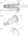
- a master brake cylinder arrangement 10 is shown in a sectional view containing a displacement axis V.
- the master cylinder assembly 10 includes a housing assembly 12 that receives a piston assembly 13.
- the housing arrangement 12 comprises a first housing part 14 which is cylindrical in sections and which provides an input chamber 16 for a force input member 19.
- the first housing part 14 is designed as an element that can be handled separately from a second housing part 18, but is firmly screwed to it.
- a fastening region 27 for fastening the master brake cylinder arrangement 10 in the engine compartment of a vehicle is formed on the first housing part 14.
- the piston arrangement 13 comprises a first piston 20 which is coupled to the force input member 19. Furthermore, the piston arrangement 13 comprises a second piston 22, which is coupled to the first piston 20 via a return spring 24, among other things.
- the pistons 20, 24 delimit a pressure chamber 28 with a cylinder bore 26 extending axially along the displacement axis V.
- the pressure chambers 28 can each be coupled in a known manner to a pedal counterforce simulator, a brake fluid reservoir or, in the event of a system failure, directly to a brake circuit of a motor vehicle (not shown ).
- the force input member 19 is designed as a multi-part piston-shaped element. At its end facing away from the first housing part 14, the force input member 19 comprises a coupling section 26 for coupling to a brake pedal (not shown). As will be explained in detail below, the force input member 19 can also be displaced along a displacement axis V relative to the housing arrangement 12 and, in particular, can be pushed into and withdrawn from the first housing part 14.
- the force input member 19 extends through an input opening 36 of the first housing part 14 into an axial blind hole 32 in the first piston 20, the blind hole 32 facing the input opening 36.
- an end of the force input member 19 facing the first piston 20 is caulked with a receiving sleeve 38 of the first piston 20. Consequently, a displacement movement of the force input member 19 can be transmitted to the first piston and, via the restoring spring 24, also to the second piston 20, 22.
- a driver element in the form of a driver disk 40 is also screwed into the blind hole 32. This has a larger outer diameter than the first piston 20, but also than the second piston 22 or the cylinder bore 26.
- a further return spring 24 is arranged between the drive plate 40 and an opposite end face region of the first housing part 14. This receives the first piston 20 essentially coaxially and extends along the displacement axis V.
- Figure 1 shows the master cylinder arrangement 10 in a starting position or, in other words, in a braking inactive rest position.
- the force input element 19 is activated in accordance with a brake pedal operation Figure 1 moved to the left along the displacement axis V.
- the pistons 20, 22 move within the cylinder bore 26 and reduce the volume of the respectively assigned pressure chambers 28.
- the return springs 24 are compressed in the process. If the driver no longer exerts an actuating force on the brake pedal or the force input member 19, the return springs 26 push the pistons 20, 22 back into their starting position.
- the piston arrangement 13 comprises the two pistons 20, 22 as well as the force input member 19 and the return springs 24 positioned between them. Overall, the piston arrangement 13 is also designed in a known manner according to the tandem cylinder design.
- the actual pressure piston unit of the piston arrangement 13, on the other hand, only comprises the pistons 20, 22, the first piston 20 being constructed in several parts and also comprising the driver plate 40 described above.
- a coupling arrangement 42 is also arranged on the drive plate 40, via which it is coupled to a rod-shaped position transmitter element 44.
- the position transmitter element 44 has a longitudinal axis L which extends parallel to the displacement axis V. Furthermore, the position transmitter element 44 has an essentially circular cross section with a diameter that varies in the end regions.
- FIG. 1 the master brake cylinder arrangement 10 and in particular the position transmitter element 44 are not shown in full. However, one recognizes a first free end section 46 of the position transmitter element 44, which interacts with the coupling arrangement 42. Proceeding from this, the position transmitter element 44 extends in a straight line along the longitudinal axis L. A second end section 47 opposite the first end section 46 (see FIG Figure 2A ) of the position transmitter element 44 is designed to be coupled mechanically with no play to a downstream detection unit. Movements of the second end section can therefore be detected in a known manner by a schematically indicated detection unit 48 which comprises a magnetic field sensor (for example a Hall sensor).
- a schematically indicated detection unit 48 which comprises a magnetic field sensor (for example a Hall sensor).
- the position transmitter element 44 and the driver plate 40 are essentially axially rigid or, in other words, axially backlash-free coupled to one another according to the example shown. This takes place via the coupling arrangement 42 explained below. This is designed to essentially completely suppress an axial relative movement between the position transmitter element 44 and the drive plate 40.
- FIG. 2A shows only a section of a master cylinder arrangement 10, which is analogous to the example from Figure 1 is trained. It shows Figure 2A a partial sectional view of this section, whereas Figure 2B includes a perspective view thereof.
- Figure 2A shows only a section of a master cylinder arrangement 10, which is analogous to the example from Figure 1 is trained. It shows Figure 2A a partial sectional view of this section, whereas Figure 2B includes a perspective view thereof.
- the first piston 20 and the associated return springs 24 can be seen.
- the force input member 19 and the drive plate 40 coupled to the piston 20 are shown again.
- the position transmitter element 44 and the coupling arrangement 42 between the drive plate 40 and the position transmitter element 44 are also shown.
- the drive plate 40 forms a radially protruding area of the piston arrangement 13 and has a larger diameter than the first piston 20, which delimits the pressure chamber 28.
- the diameter of the driver disk 40 is selected such that it lies axially opposite the first end section 46 of the position transmitter element 44.
- the driver plate 40 is connected upstream of the position transmitter element 44 so that it can move it in the manner described above by transmitting compressive forces.
- Figure 2C shows the coupling arrangement 42 in a perspective individual representation.
- a first section 50 can be seen, which forms an open annular area.
- the annular area spans an angular range of approx. 270 ° or, in other words, is open in the circumferential direction over an angular range of approx. 90 °.
- the coupling arrangement 42 can be coupled to the drive plate 40 by means of this first section 50.
- the first section 50 comprises at its respective free ends two mutually facing and radially inwardly protruding sections 51. These are received in a recess 54 of the driver disk 40, which is explained below.
- the drive plate 40 comprises a coupling surface 52 that runs around the displacement axis V but faces away from it (see FIG Figure 2A ).
- the coupling surface 52 in turn comprises a recess 54, which is designed as a groove running around the displacement axis V.
- the recess 54 provides a radial indentation region running around in the circumferential direction within the coupling surface 52.
- the first section 50 of the coupling arrangement 42 can be at least partially received in this recess 54. In the assembled state according to Figure 2A The first section 50 of the coupling arrangement 42 accordingly also extends around the displacement axis V along the recess 54.
- An axial extension of the recess 54 is also dimensioned such that the first section 50 is arranged therein without any axial play. This prevents relative axial movements between the driver disk 40 and the coupling arrangement 42.
- a diameter step 55 of the driver disk 40 which is positioned between the recess 54 and the position transmitter element 44 and which extends from the recess 54, is provided. This provides an axial stop area for the second section 50 of the coupling arrangement 42. This prevents an axial relative movement between the coupling arrangement 42 and the drive plate 40, at least in the case of a brake-active displacement in Figure 2A additionally supported to the left.
- the first section 50 When the coupling arrangement 42 is arranged on the driver disk 40, the first section 50 is pushed radially inward onto the driver disk 40.
- the first section 50 is elastically expanded and, in particular, lies against the base of the recess 54 via the radially inwardly projecting sections 51.
- a corresponding radially inwardly protruding section 51 is also found in the area of a second section 56, which is explained below. Due to the elastic deformation of the first section 50, defined frictional forces are generated between the respective radially inwardly protruding sections 51 and the drive plate 40.
- the rotatability of the coupling arrangement 42 about the displacement axis V explained below, can be set in a defined manner.
- the second section 56 comprises a first axial subsection 58 which, starting from the first section 50, extends parallel to the displacement axis V in the direction of the position transmitter element 44 (see FIG Figure 2A ).
- the axial section 58 spans at least partially the first end section 46 of the position transmitter element 44.
- the axial section 58 merges into a radial section 60. Starting from the axial section 58, this extends radially inward or radially inward (that is, in the direction of the displacement axis V).
- the radial subsection 60 comprises a recess 62 which is open radially inward.
- the first end section 46 furthermore comprises an area 64 of reduced diameter, which merges into an end piece 66 with an enlarged diameter.
- a diameter step is provided within the first end section. This can be introduced radially into the recess 62 of the second section 56 of the coupling arrangement 42.
- the end section 66 comes into contact with one of the drive plates 40 facing side of the radial subsection 60. This forms a form fit, which suppresses an axial relative sliding between the coupling arrangement 42 and the position transmitter element 44.
- the second section 50 can be moved along the recess 54 and thus can slide on the coupling surface 52 in the circumferential direction. This is accompanied by a relative rotation between the coupling section 42 and the piston arrangement 13 (or the driver plate 40) about the displacement axis V. If the drive plate 40 rotates about the displacement axis V during operation, the coupling section 22 and thus also the position transmitter element 44 can remain in an essentially constant angular position about the displacement axis V, since the drive plate 40 is largely decoupled from the coupling section 42 in terms of rotation .
- position transmitter element 44 is held in an axial guide sleeve or bushing (not shown). If the drive plate 40 rotates, it can slip around the displacement axis V relative to the essentially stationary coupling section 42 without the rotational forces acting thereby being able to act on the position transmitter element 44 or the coupling section 42 in a displaceable manner.
- the coupling arrangement 42 thus has two defined sections 50, 56 which enable a separation of functions. More precisely, the second section 56 is designed in particular for coupling to the position transmitter element 44, whereas the first section 50 is primarily intended for coupling to the driver disk 40. Furthermore, the first section 50 provides the rotational degree of freedom of the coupling arrangement 42 relative to the driver disk 40, whereas the second section 56 primarily serves for the fixed and, in particular, axially play-free connection to the position transmitter element 44. As explained, however, the first section 50 is also arranged axially free of play on the drive plate 40 and therefore supports the axially play-free coupling.
- the Figures 3A-C show a second embodiment.
- the piston arrangement 13 comprising a driver plate 40.
- a coupling arrangement 42 which enables a connection to the position transmitter element 44, is again arranged on its outer circumferential surface.
- the coupling arrangement 42 comprises a first section 50 for coupling to the piston arrangement 13 or the drive plate 40, this first section 50 being designed as a closed ring.
- a plurality of radially inwardly protruding first regions 51 are formed on a side of the first section 50 facing away from the position transmitter element 44. The same applies to a side facing the position transmitter element 44, on which a plurality of radially inwardly protruding second regions 52 are also formed.
- the coupling arrangement 42 is made of an elastically deformable plastic material. As from the Figures 3A-B As can be seen, it can therefore be pushed or slipped axially over the drive plate with an elastic deformation in order to be coupled with it without axial play.
- the drive plate 40 comprises an outer circumferential surface with the largest diameter, which forms a coupling surface 52 for fastening the first section 50.
- a recess 54 running around the circumference, which is step-shaped.
- a diameter step 55 facing the position transmitter element 44 is thus provided, which extends from the recess 54.
- the step-shaped structure formed by the recess 54 and diameter step 55 can be encompassed by the radially inwardly protruding areas 51, 52 of the first section 50, so that the coupling arrangement 42 and the drive plate 40 are coupled axially without play. This can optionally also take place with a targeted adjustment of frictional forces, for example by defining the elastic degree of deformation when arranging the first section 50 on the drive plate 40. A sufficiently reliable fastening can be achieved in this way, but without a relative rotatability of these elements about the displacement axis V. suppress.
- the second section 56 of the coupling arrangement 42 can be seen again.
- This again comprises an axial section 58 as well as a radial section 60.
- the radial section 60 extends radially outward from the axial section 58.
- the radial subsection 60 comprises a recess 62 which is open radially outward.
- An end section 46 of the position transmitter element 44 can accordingly be coupled to the second section 56 by a movement directed radially inward.
- a form fit is produced between the recess 62 and the end section 46, which, analogously to the previous example, comprises a diameter step based on a diameter-reduced area 64 which merges into an end piece 66 with an enlarged diameter.
- the Figures 4A-C show a third embodiment.
- the piston arrangement 13 is identical to the piston arrangement from FIG Figure 3A educated. Consequently, the driver disk 40 in turn comprises an outer circumferential surface with the largest diameter, which serves as a coupling surface 52 and comprises a circumferential recess 54 and a diameter step 55.
- the coupling arrangement 42 is again designed as an open ring, analogous to the first exemplary embodiment according to FIG Figures 2A-C . Especially in Figure 4C it can be seen, however, that the coupling arrangement 42 is designed with a significantly larger axial extent than in the first exemplary embodiment.
- the coupling arrangement 42 in turn comprises a first section 50, which is designed as a correspondingly opened annular region.
- first section 50 which is designed as a correspondingly opened annular region.
- radially inwardly protruding regions 51 are provided at the free ends of the annular first section 50. These lie against a side of the drive plate 40 facing the position transmitter element 44.
- the first section 50 On an inner circumferential surface 70 facing the driver disk, the first section 50 also comprised a circumferential recess 54.
- the coupling arrangement 42 and position transmitter element 54 are again connected via a second section 56.
- this is designed as a recess in the first section 50.
- This recess extends in particular in the axial direction and thus provides a free space in which the end section 46 of the position transmitter element 54 can be received.
- the second section 56 further comprises an axial input region 72 which is designed with a reduced cross section and thus provides an undercut. This can interact with a diameter step of the end section 46 of the position transmitter element 44, which is configured analogously to the previous examples, in order to provide an axial form fit and thus an axially rigid coupling between the position transmitter element 44 and the coupling arrangement 42.
- the coupling arrangement 42 thus again enables an axially rigid coupling of the position transmitter element 44 and the piston arrangement 13, but also provides a rotational decoupling of these elements about the displacement axis V.
- the coupling arrangement 42 also enables the previously explained axially rigid coupling of the position transmitter element 44 and the piston arrangement 13 with a simultaneous rotational decoupling about the displacement axis V.
- the end section 46 of the position transmitter element 44 can optionally rest on the drive plate 40, the coupling arrangement 42 or other elements, which in turn can be supported by any restoring forces due to an elastic deformation of the coupling arrangement 42.
- FIGS. 5A-C show a fourth embodiment.
- the piston arrangement 13 is designed analogously to the previous example.
- the driver disk 40 has an enlarged axial extent in its area with the largest diameter compared to the previous examples.
- the driver disk 40 comprises a radially outer ring section 80 which runs around the circumference.
- the ring section 80 Starting from a disk-shaped base section 82 running orthogonally to the displacement axis V, the ring section 80 extends axially along the displacement axis V as well as in the direction of FIG Figure 5A pressure chamber 28, not shown. Accordingly, it forms a hollow cylindrical receiving section 84 of the drive plate 40, in which the return spring 24 positioned near the inlet opening 36 (see FIG. Figure 1 ) can be recorded in sections. More precisely, one end of the return spring 24 facing the inlet opening 36 is supported on the base section 82 and is axially spanned in sections by the ring section 80.
- An outer circumferential surface is provided on the ring section 80 and serves as a coupling surface 52 for interacting with the coupling arrangement 42.
- a circumferential recess 54 in the form of a groove is provided in the coupling surface 52.
- a first section 50 of the coupling arrangement 42 is received here without axial play.
- the coupling arrangement 42 comprises a first section 50 which is designed as an open ring. The opening in this ring spans an angular range of less than 10 ° and defines the second section 56 for coupling to the position transmitter element 44.
- the coupling arrangement 42 can be arranged with the widening of the first section 50 in the recess 54 of the drive plate 40, it also being possible to set defined frictional forces (see the discussion analogous to the previous examples).
- the coupling arrangement 42 can be pushed radially onto the drive plate 40.
- the end section 46 of the position transmitter element 44 can then be pushed axially through the opening in the first section 50 which forms the second section 56.
- the first section 50 is widened slightly. Due to the diameter step in the end section 46, which is designed analogously to the previous examples, the first section 50 narrows, however, as soon as the end piece 66 of the position transmitter element 44 has been pushed through the opening.
- the first section 50 snaps back together behind the end piece 66, so that an axial form fit is formed.
- the end piece 66 comes into contact with a diameter step 86 of the drive plate 40 in order to secure the axial position of the position transmitter element 44 (see Fig. Figure 5A ).
- the rotational decoupling takes place in turn via a relative slipping of the first section 50 of the coupling arrangement 42 along the recess 54 of the drive plate 40.
- the Figures 6A-C show a fifth embodiment. This includes a driver plate 40 designed analogously to the fourth exemplary embodiment.
- the coupling arrangement 42 is designed as an open ring which is inserted into the circumferential recess 54 of the driver plate 40 without axial play.
- the coupling arrangement 42 comprises a first section 50 which defines an opened ring section.
- the first section 50 spans an angular range of approximately 240 °.
- the first section 50 has three radially inwardly projecting regions 51 along its circumference. These are each arranged at the free ends of the first section 50 and a third area 51 is positioned centrally between them.
- the protruding areas 51 form guide surfaces which interact with the bottom of the recess 54.
- the arrangement of the coupling arrangement 42 in the recess 54 again takes place via an elastic widening of the first section 50 in order to set predetermined frictional forces which, however, still allow a relative rotation between the drive plate 40 and the coupling arrangement 42 about the displacement axis V.
- recesses 88 are formed in the free end regions of the first section 50, each of which extends radially inward and into which the end section 46 can be moved radially. These recesses 88 each form a second section 56 for connecting the coupling arrangement 42 and position transmitter element 44. In principle, such a recess 88 is sufficient in only one of the end regions.
- the recesses 88 can also be elastically deformed during coupling with the position transmitter element 44 (for example by widening) in order to ensure a secure connection.
- the engaged recess 88 forms, together with the end piece 66 of the position transmitter element 44, an axial form fit, the end piece 66 in turn coming into contact with a diameter step 86 of the drive plate 40 (see FIG. Figure 6A ).
- the axial fixing of the end section 46 thus corresponds to that of the previous fourth embodiment.
- Rotational decoupling is in turn made possible by a relative slipping of the first section 50 along the recess 54.
- the Figures 7A-B show a sixth embodiment.
- the coupling arrangement 42 is designed analogously to the fifth starting example, which is why it is not explained in more detail.
- the drive plate 40 itself is designed with an axially shortened ring section 80 which, however, in turn provides a receiving area 84 for the return spring 24.
- the drive plate 40 in turn comprises an outer circumferential surface which forms a coupling surface 52.
- a circumferential recess 54 in the form of a groove is provided in this, in which the coupling arrangement 42 is accommodated analogously to the fourth exemplary embodiment.
- the Figures 8A-C show a seventh embodiment.
- the piston arrangement 13 including the driver plate 40 is designed analogously to the second exemplary embodiment.
- the coupling arrangement 42 is fastened to the drive plate 40 without axial play via these areas 51, 52.
- the coupling with the position transmitter element takes place via a second section 56, which is designed as a clamping section protruding axially from the first section 50.
- the second section 56 comprises two clamp sections 90 which extend axially in the direction of the position transmitter element 44 and lie opposite one another and which form a receiving area for the end section 46 of the position transmitter element 44.
- This end section 46 can be pushed axially into the second section 56 with the clamp sections 90 being elastically urged apart. Due to the diameter step in the end section 46, which is designed analogously to the second example, the chamber sections 90 narrow again as soon as the end piece 66 has been completely inserted.
- the chamber sections 90 each include an undercut area which then comes into engagement with the diameter step in the end section 46 and forms an axial form fit.
- the end piece 66 (optional) is in contact with an opposite end face of the first section 50 of the coupling arrangement 42.
- FIG. 8D shows a further variant of the seventh embodiment.
- an additional fastening element in the form of a retaining clip 92 is provided. This is designed as a bent wire element and is pushed onto the axial ends of the clamp sections 90 in order to additionally urge them towards one another. As a result, an additional fastening force is generated which reinforces the engagement or form fit between the end section 46 and the coupling arrangement 42 and the axially rigid coupling between them.
- the Figures 9A-C show an eighth embodiment.
- the piston arrangement 13 is analogous to the fourth exemplary embodiment according to FIG Figures 5A-C and has a ring section 80 and a recess 54 running in the circumferential direction.
- a coupling arrangement 42 is in turn received in this.
- this is designed with a significantly smaller size compared to the previous starting examples.
- the coupling arrangement 42 is designed as a one-piece bent sheet metal part which comprises a first section 50 with a rounded underside 92 facing the recess 54.
- This underside 92 provides a guide surface, by means of which the coupling arrangement 42 rests on the base of the recess 54 and can be moved along this in the circumferential direction (and thus about the displacement axis V) relative to the drive plate 40.
- the recess 54 is also dimensioned in such a way that the coupling arrangement 42 is received therein without axial play.
- the second section 56 of the coupling arrangement 42 for coupling to the position transmitter element 44 is designed as a recess that is open radially inward.
- the end section 46 of the position transmitter element 44 can be received therein, analogously to the first exemplary embodiment, with the formation of an axial form fit.
- the coupling arrangement 42 is then inserted into the recess 54. In Figure 9A it can be seen that this is done again by bringing the end piece 66 of the position transmitter element 44 into contact with a diameter step 86 of the driver disk 40.
- the coupling arrangement 42 is in turn designed to decouple the drive plate 40 and the position transmitter element 44 in a rotational manner, since the coupling arrangement 42 can slide along the recess 54.
- it further comprises a contact section 94 facing away from the underside 92, which is formed by an axially bent region of the coupling arrangement 42.
- This contact section 94 is in contact with an in Figure 9A Housing wall 98, indicated by dashed lines, of the master brake cylinder arrangement 10.
- the housing wall 98 is formed by a hollow cylindrical cover element 100 coaxially receiving the displacement axis V.
- the contact section 94 is always in contact with an opposite region of the housing wall 98, that is to say, for example, also in an in Figure 9A upper position near reference number 54.
- FIGS 10A-C show a ninth embodiment. This represents a comparable variant to the eighth starting example.
- the piston arrangement 13 including the driver plate 40 is again analogous to the fourth exemplary embodiment according to FIG Figures 5A-C educated.
- the coupling arrangement 42 is again designed with a reduced structural size.
- the first section 50 comprises a significantly shorter underside 92, which is received in the recess 54 without play axially and so that it can be moved relative to the circumference.
- the first section 50 merges directly into a radial subsection 60 of a second section 56 of the coupling arrangement 42 which, analogously to the first exemplary embodiment, comprises a recess 62 opening radially inward.
- the second section 56 further comprises an axial subsection 58.
- This comprises two angled holding sections 102, which bear against a side of the diameter step 86 of the driver disk 40 facing away from the position transmitter element 44.
- An axially running arm section 104 extends starting from the holding sections 102. At their ends facing away from the holding sections 102, the arm sections 104 are connected by a circumferential section 106. Proceeding from this, another radial section 60 of the second section 56 extends.
- the axial position of the coupling arrangement 42 on the drive plate 13 is supported by the first section 50 but also by the Retaining sections 102 secured. Overall, there is thus again an axially backlash-free and axially rigid coupling of the position transmitter element 44 and the piston arrangement 13 via the coupling arrangement 42, which, however, is movable about the displacement axis V relative to the drive plate 40.
Description
Die vorliegende Erfindung betrifft allgemein das technische Gebiet von Hauptbremszylinderanordnungen und insbesondere Hauptbremszylinderanordnungen für Kraftfahrzeugbremsanlagen. Genauer gesagt betrifft die vorliegende Erfindung eine Hauptbremszylinderanordnung, bei der eine Bremspedalbetätigung mittels eines Positionsgeberelements erfassbar ist.The present invention relates generally to the technical field of master cylinder assemblies and, more particularly, to master cylinder assemblies for motor vehicle brake systems. More precisely, the present invention relates to a master brake cylinder arrangement in which an actuation of the brake pedal can be detected by means of a position transmitter element.
Lösungen zur Erfassung einer Bremspedalbetätigung sind aus dem Stand der Technik bekannt. Eine solche Erfassung ist beispielsweise erforderlich, um das Vorliegen eines Fahrerwunsches hinsichtlich einer Fahrzeugbremsung und gegebenenfalls auch das gewünschte Ausmaß der Fahrzeugbremsung zu erfassen. Diese Information kann verwendet werden, um die bei einem fahrerentkoppelten Bremsbetrieb bereitzustellenden Bremskräfte zu ermitteln (Brake-By-Wire). Derartige Bremskräfte werden typischerweise über einen elektromechanischen Bremsaktuator erzeugt.Solutions for detecting a brake pedal actuation are known from the prior art. Such a detection is necessary, for example, in order to detect the presence of a driver's request with regard to vehicle braking and possibly also the desired extent of vehicle braking. This information can be used to determine the braking forces to be provided in a braking operation that is decoupled from the driver (brake-by-wire). Such braking forces are typically generated via an electromechanical brake actuator.
In diesem Zusammenhang ist es ferner bekannt, ein Positionsgeberelement bereitzustellen, das nach Maßgabe der Bremspedalbetätigung verlagerbar ist, wobei diese Verlagerung mittels einer Erfassungseinheit erfasst wird. Hierfür kommen beispielsweise stabförmige Positionsgeberelemente in Betracht, die mit dem Kolben eines Hauptbremszylinders für eine gemeinsame Verlagerung gekoppelt sind.In this context, it is also known to provide a position transmitter element which can be displaced in accordance with the actuation of the brake pedal, this displacement being detected by means of a detection unit. For this purpose, for example, rod-shaped position transmitter elements come into consideration, which are coupled to the piston of a master brake cylinder for common displacement.
Beispiele hierfür finden sich in den Dokumenten
Ferner offenbart die Druckschrift
Es hat sich jedoch gezeigt, dass es bei den bekannten Lösungen leicht zu Fehlfunktionen kommen kann und dass eine gewünschte Zuverlässigkeit oft nicht erreicht wird.It has been shown, however, that malfunctions can easily occur with the known solutions and that the desired reliability is often not achieved.
Es ist eine Hauptbremszylinderanordnung anzugeben, die eine zuverlässige Erfassung einer Bremspedalbetätigung ermöglicht.A master brake cylinder arrangement is to be specified which enables reliable detection of a brake pedal actuation.
Hierfür wird eine Hauptbremszylinderanordnung für eine Kraftfahrzeugbremsanlage bereitgestellt, umfassend wenigstens eine Kolbenanordnung mit:
- einer Druckkolbeneinheit, die entlang einer Verlagerungsachse verlagerbar ist und gemeinsam mit einer Gehäuseanordnung der Hauptbremszylinderanordnung eine Druckkammer begrenzt,
- einem Krafteingangsglied, das nach Maßgabe einer Bremspedalbetätigung verlagerbar ist und mit der Druckkolbeneinheit für eine gemeinsame Verlagerung gekoppelt oder koppelbar ist.
- a pressure piston unit which can be displaced along a displacement axis and, together with a housing arrangement of the master brake cylinder arrangement, delimits a pressure chamber,
- a force input member which can be displaced in accordance with the actuation of the brake pedal and which is coupled or can be coupled to the pressure piston unit for a common displacement.
Die Hauptbremszylinderanordnung umfasst ferner:
- ein Positionsgeberelement, das nach Maßgabe einer Betätigung des Krafteingangsgliedes verlagerbar ist;
- eine Erfassungseinheit, die dazu ausgebildet ist, eine Verlagerung des Positionsgeberelements zu erfassen; und
- eine Kopplungsanordnung, die dazu ausgebildet ist, das Positionsgeberelement mit wenigstens einem Element der Kolbenanordnung entlang der Verlagerungsachse im Wesentlichen starr zu koppeln, wobei die Kopplungsanordnung ferner dazu eingerichtet ist, eine Rotation des wenigstens einen Elements der Kolbenanordnung relativ zu dem Positionsgeberelement um die Verlagerungsachse zuzulassen.
- a position transmitter element which is displaceable in accordance with an actuation of the force input member;
- a detection unit which is designed to detect a displacement of the position transmitter element; and
- a coupling arrangement which is designed to couple the position transmitter element with at least one element of the piston arrangement along the displacement axis essentially rigidly, wherein the coupling arrangement is further configured to allow a rotation of the at least one element of the piston arrangement relative to the position transmitter element about the displacement axis.
Die Druckkolbeneinheit kann einen Kolben zum Beispiel in Form eines Druck- und/oder Bremskolbens umfassen, der in einer Zylinderbohrung der Hauptbremszylinderanordnung verlagerbar geführt ist. Die Gehäuseanordnung kann ein Zylindergehäuse der Hauptbremszylinderanordnung umfassen. Die Druckkolbeneinheit und die Zylinderbohrung (und/oder das Zylindergehäuse) können gemeinsam die Druckkammer begrenzen. Nach Maßgabe einer Verlagerung des Kolbens kann das Volumen der Druckkammer variiert werden, sodass in bekannter Weise ein Druck auf den Pedalgegenkraftsimulator oder bei einem Systemversagen direkt ein Bremsdruck in einem mit der Hauptbremszylinderanordnung gekoppelten hydraulischen Bremskreislauf verändert werden kann.The pressure piston unit can comprise a piston, for example in the form of a pressure and / or brake piston, which is guided displaceably in a cylinder bore of the master brake cylinder arrangement. The housing arrangement can comprise a cylinder housing of the master brake cylinder arrangement. The pressure piston unit and the cylinder bore (and / or the cylinder housing) can jointly delimit the pressure chamber. Depending on the displacement of the piston, the volume of the pressure chamber can be varied so that, in a known manner, pressure is exerted on the pedal counterforce simulator or in the event of a system failure a brake pressure in a hydraulic brake circuit coupled to the master brake cylinder arrangement can be changed directly.
Es versteht sich, dass die Hauptbremszylinderanordnung auch mehrere solcher Druckkolbeneinheiten umfassen kann, die beispielsweise nach Tandembauart angeordnet sind. Diese können auch eine entsprechende Mehrzahl von Druckkammern definieren.It goes without saying that the master brake cylinder arrangement can also comprise a plurality of such pressure piston units, which are arranged, for example, in a tandem design. These can also define a corresponding plurality of pressure chambers.
Die Druckkolbeneinheit kann mehrteilig aufgebaut sein. Beispielsweise kann die Druckkolbeneinheit einen im Wesentlichen zylindrisches Kolben umfassen. Dieser kann zumindest abschnittsweise unmittelbar in die Druckkammer hinein und/oder aus dieser heraus verlagerbar sein. An dem Kolben können weitere Elemente der Druckkolbeneinheit angebracht sein, beispielsweise eine Aufnahmebuchse für einen Verbindungsabschnitt des Krafteingangsgliedes und/oder ein Mitnehmerelement (zum Beispiel eine Mitnehmerscheibe). Diese Elemente können zumindest teilweise in einer zylindrischen Sacklochbohrung oder Ausnehmung in dem Kolben angeordnet sein. Das Mitnehmerelement kann ferner allgemein radial von dem Kolben hervorstehen, zum Beispiel um einen dem Positionsgeberelement axial gegenüberliegenden Bereich der Druckkolbeneinheit zu bilden.The pressure piston unit can be constructed in several parts. For example, the pressure piston unit can comprise a substantially cylindrical piston. This can be displaced directly into and / or out of the pressure chamber, at least in sections. Further elements of the pressure piston unit can be attached to the piston, for example a receiving bushing for a connecting section of the force input member and / or a driver element (for example a driver disk). These elements can be arranged at least partially in a cylindrical blind hole or recess in the piston. The driver element can also protrude generally radially from the piston, for example in order to form a region of the pressure piston unit axially opposite the position transmitter element.
Das Krafteingangsglied kann als allgemein zylindrisches Element und/oder kolbenartig ausgebildet sein. Das Koppeln mit der Druckkolbeneinheit kann kraftschlüssig und/oder formschlüssig erfolgen (beispielsweise durch Verstemmen oder gemeinsames in Anlage Bringen). Auch mit dem Bremspedal kann ein zumindest mittelbares mechanisches Koppeln erfolgen. Allgemein kann das Krafteingangsglied ebenfalls entlang der Verlagerungsachse verlagerbar sein, wobei es eine Bremspedalbetätigung in eine Verlagerung der Druckkolbeneinheit entlang der Verlagerungsachse umsetzen kann.The force input member can be designed as a generally cylindrical element and / or piston-like. The coupling with the plunger unit can be non-positive and / or positive (for example by caulking or jointly bringing them into contact). At least indirect mechanical coupling can also take place with the brake pedal. In general, the force input element can also be displaceable along the displacement axis, it being able to convert a brake pedal actuation into a displacement of the pressure piston unit along the displacement axis.
Das Positionsgeberelement kann als ein allgemein langgestrecktes und/oder zylindrisches Element ausgebildet sein. Gemäß einem Beispiel ist das Positionsgeberelement im Wesentlichen stabförmig und/oder zumindest abschnittsweise mit einem gerundeten, ovalen oder kreisrunden Querschnitt ausgebildet. Das Positionsgeberelement kann auch als Positionsgeberstab oder Sensorstift bezeichnet werden. Übergeordnet kann das Positionsgeberelement ein metallisches und insbesondere ein magnetisches Material umfassen und/oder allgemein dazu eingerichtet sein, mit der Erfassungseinheit für eine Positionserkennung zu wechselwirken. Hierzu kann die Erfassungseinheit einen Magnetfeldsensor umfassen.The position transmitter element can be designed as a generally elongated and / or cylindrical element. According to one example, the position transmitter element is essentially rod-shaped and / or at least in sections with a rounded, oval or circular cross section. The position transmitter element can also be referred to as a position transmitter rod or sensor pin. At a higher level, the position transmitter element can comprise a metallic and, in particular, a magnetic material and / or can generally be set up with the detection unit for a To interact with position detection. For this purpose, the detection unit can comprise a magnetic field sensor.
Das Positionsgeberelement kann mit der Druckkolbeneinheit oder dem Krafteingangsglied koppelbar oder gekoppelt sein, um gemeinsam mit diesen verlagert zu werden. Dies kann über die nachfolgend erläuterte Kopplungsanordnung erfolgen. Die Verlagerung des Positionsgeberelements kann ebenfalls im Wesentlichen entlang der Verlagerungsachse erfolgen. Insbesondere kann das Positionsgeberelement entlang einer von der Verlagerungsachse beabstandeten aber hierzu parallelen Achse verlagert werden.The position transmitter element can be coupled or coupled to the pressure piston unit or the force input member in order to be displaced together with them. This can be done using the coupling arrangement explained below. The displacement of the position transmitter element can also take place essentially along the displacement axis. In particular, the position transmitter element can be displaced along an axis spaced apart from the displacement axis but parallel thereto.
Die Erfassungseinheit kann die Bewegungen des Positionsgeberelements mittels einer geeigneten Sensoreinheit erfassen, beispielsweise einer Magnetfeldsensoreinheit, umfassend einen Hall-Sensor. Die Erfassungseinheit kann ferner von einer elektromechanischen Bremsaktuatoreinheit umfasst sein oder mit dieser wechselwirken. Insbesondere kann die Erfassungseinheit Bestandteil einer Sensoreinheit zum Erfassen eines Betriebsparameters der Bremsaktuatoreinheit sein, wie beispielsweise einer aktuellen Position eines Elektromotors dieser Einheit. Die Erfassungseinheit kann allgemein dazu ausgebildet sein, nach Maßgabe der Verlagerung des Positionsgeberelements Signale zu generieren. Diese können von einer Steuereinheit ausgewertet werden. Die Steuereinheit kann von der Erfassungseinheit umfasst oder zumindest hiermit verbindbar sein.The detection unit can detect the movements of the position transmitter element by means of a suitable sensor unit, for example a magnetic field sensor unit comprising a Hall sensor. The detection unit can also be comprised by an electromechanical brake actuator unit or interact with it. In particular, the detection unit can be part of a sensor unit for detecting an operating parameter of the brake actuator unit, such as a current position of an electric motor of this unit. The detection unit can generally be designed to generate signals in accordance with the displacement of the position transmitter element. These can be evaluated by a control unit. The control unit can be included in the detection unit or at least be connectable to it.
Die Kopplungsanordnung kann allgemein eine zwischen dem Positionsgeberelement und dem wenigstens einem Element der Kolbenanordnung zwischengeschaltete Einheit bilden. Dies kann insbesondere ein mechanisches Zwischenschalten oder Zwischenpositionieren einschließen, sodass die Kolbenanordnung und das Positionsgeberelement mittelbar über die Kopplungsanordnung verbunden sind. Abseits der Kopplungsanordnung können im Wesentlichen keine weiteren mittelbaren und/oder unmittelbaren mechanischen Kopplungen zwischen dem Positionsgeberelement und der Kolbenanordnung vorgesehen sein.The coupling arrangement can generally form a unit interposed between the position transmitter element and the at least one element of the piston arrangement. This can in particular include mechanical interconnection or intermediate positioning, so that the piston arrangement and the position transmitter element are connected indirectly via the coupling arrangement. Apart from the coupling arrangement, essentially no further indirect and / or direct mechanical couplings can be provided between the position transmitter element and the piston arrangement.
Zusätzlich oder alternativ kann eine Kraftübertragung zwischen der Kolbenanordnung und dem Positionsgeberelement zur gemeinsamen Verlagerung im Wesentlichen über die Kopplungsanordnung erfolgen und insbesondere im Wesentlichen ausschließlich über die Kopplungsanordnung.Additionally or alternatively, a force transmission between the piston arrangement and the position transmitter element for joint displacement can take place essentially via the coupling arrangement and in particular essentially exclusively via the coupling arrangement.
Die Kopplungsanordnung kann eine von der Kolbenanordnung separat ausgebildete und/oder separat handhabbare Baugruppe umfassen und/oder bilden. Diese kann mit dem wenigstens einen Element der Kolbenanordnung verbindbar und beispielsweise unmittelbar daran befestigbar sein.The coupling arrangement can comprise and / or form an assembly which is designed separately from the piston arrangement and / or can be handled separately. This can be connected to the at least one element of the piston arrangement and, for example, can be fastened directly thereto.
Beispielsweise kann die Kopplungsanordnung ein separat ausgebildetes Element umfassen, das mit der Kolbenanordnung verbindbar ist und das optional wenigstens einen der nachstehend erläuterten ersten und zweiten Abschnitte umfasst. Zusätzlich oder alternativ kann die Kopplungsanordnung bzw. dessen etwaiges separat ausgebildetes Element einstückig ausgebildet und insbesondere aus einem Blechmaterial hergestellt sein (zum Beispiel als Blechbiege- oder Stanzteil).For example, the coupling arrangement can comprise a separately formed element which can be connected to the piston arrangement and which optionally comprises at least one of the first and second sections explained below. Additionally or alternatively, the coupling arrangement or its possible separately formed element can be formed in one piece and in particular made from a sheet metal material (for example as a bent sheet metal or stamped part).
Das axial starre Koppeln von Positionsgeberelement und Kolbenanordnung kann ein Begrenzen oder im Wesentlichen vollständiges Unterdrücken einer axialen Relativbewegung zwischen den genannten Elementen entlang der Verlagerungsachse betreffen. Anders ausgedrückt kann die Kopplungsanordnung derart ausgebildet sein, dass das Positionserfassungselement und die Kolbenanordnung gemeinsam entlang der Verlagerungsachse bewegbar sind, ohne dass es zu signifikanten axialen Relativbewegungen oder einem axialen Spiel zwischen diesen Elementen kommt.The axially rigid coupling of the position transmitter element and the piston arrangement can relate to a limiting or essentially complete suppression of an axial relative movement between the said elements along the displacement axis. In other words, the coupling arrangement can be designed such that the position detection element and the piston arrangement can be moved together along the displacement axis without significant axial relative movements or axial play occurring between these elements.
Hingegen kann die Kopplungsanordnung dazu ausgebildet sein, eine relative Rotation zwischen Positionsgeberelement und Kolbenanordnung um die Verlagerungsachse zu ermöglichen. Die Kolbenanordnung kann bei einer Rotation um die Verlagerungsachse also sozusagen relativ zu der Kopplungsanordnung verrutschen, ohne dass es zu einer signifikanten Übertragung dieser Rotationsbewegung auf das Positionsgeberelement kommt, womit eine rotationsbedingte Querkraftbelastung auf das Positionsgeberelement reduziert bzw. verhindert wird.In contrast, the coupling arrangement can be designed to enable a relative rotation between the position transmitter element and the piston arrangement about the displacement axis. When rotating about the displacement axis, the piston arrangement can slip relative to the coupling arrangement, so to speak, without a significant transfer of this rotational movement to the position transmitter element, whereby a rotational transverse force load on the position transmitter element is reduced or prevented.
Anders ausgedrückt kann die Kopplungsanordnung das Positionsgeberelement und die Kolbenanordnung im Wesentlichen rotatorisch entkoppeln, wobei dies insbesondere eine Rotation um die Verlagerungsachse betrifft. Die Kopplungsanordnung kann also allgemein dazu ausgebildet sein, im Wesentlichen lediglich axiale Kräfte zwischen den genannten Elementen zu übertragen, nicht jedoch Rotationskräfte um die Verlagerungsachse.In other words, the coupling arrangement can decouple the position transmitter element and the piston arrangement essentially in a rotational manner, this particularly relating to a rotation about the displacement axis. The coupling arrangement can thus generally be designed to transmit essentially only axial forces between the elements mentioned, but not rotational forces about the displacement axis.
Wie nachfolgend näher ausgeführt, kann die Kopplungsanordnung zum Koppeln der relevanten Elemente insbesondere mit einem Mitnehmerelement der Druckkolbeneinheit und/oder einem freien Ende des Positionsgeberelements wechselwirken.As explained in more detail below, the coupling arrangement for coupling the relevant elements can in particular with a driver element of the Interact pressure piston unit and / or a free end of the position transmitter element.
Gemäß einer weiteren Ausführungsform umfasst die Kopplungsanordnung einen ersten Abschnitt, der dazu ausgebildet ist, die Kopplungsanordnung mit dem wenigstens einen Element der Kolbenanordnung zu koppeln. Das Koppeln kann ein unmittelbares und/oder mechanisches Koppeln betreffen. Der erste Abschnitt kann insbesondere axial mit dem Element der Kolbenanordnung koppelbar sein, insbesondere axial starr. Um die Verlagerungsachse betrachtet kann der erste Abschnitt hingegen von der Kolbenanordnung rotatorisch entkoppelt sein, trotz einer etwaigen axial starren Kopplung hiermit.According to a further embodiment, the coupling arrangement comprises a first section which is designed to couple the coupling arrangement to the at least one element of the piston arrangement. The coupling can relate to a direct and / or mechanical coupling. The first section can in particular be axially coupled to the element of the piston arrangement, in particular axially rigid. On the other hand, viewed about the displacement axis, the first section can be decoupled from the piston arrangement in a rotational manner, despite any axially rigid coupling therewith.
Mit anderen Worten kann der erste Abschnitt den rotatorischen Freiheitsgrad zwischen dem Positionsgeberelement und dem Element der Kolbenanordnung zumindest anteilig, größtenteils oder im Wesentlichen vollständig bereitstellen. Zusätzlich oder alternativ kann der erste Abschnitt die axial starre Kopplung zwischen dem Positionsgeberelement und dem Element der Kolbenanordnung zumindest anteilig, größtenteils oder im Wesentlichen vollständig bereitstellen.In other words, the first section can provide the rotational degree of freedom between the position transmitter element and the element of the piston arrangement at least in part, for the most part or essentially completely. Additionally or alternatively, the first section can provide the axially rigid coupling between the position transmitter element and the element of the piston arrangement, at least partially, for the most part or essentially completely.
Der erste Abschnitt kann ferner dazu ausgebildet sein, mit einer Kopplungsfläche der Kolbenanordnung zu wechselwirken und insbesondere relativ zu dieser abzugleiten. Die Kopplungsfläche kann von einem Kopplungsbereich der Kolbenanordnung umfasst sein oder diesen bilden. Das Abgleiten kann ein Abgleiten entlang und/oder an der Kopplungsfläche betreffen (insbesondere wobei die Kopplungsfläche bewegt wird und der erste Abschnitt im Wesentlichen ortsfest bleibt). Zusätzlich oder alternativ kann dies ein relatives Abgleiten in Umfangsrichtung des wenigstens einen Elements der Kolbenanordnung betreffen, wobei die Umfangsrichtung um die Verlagerungsachse verlaufen kann.The first section can furthermore be designed to interact with a coupling surface of the piston arrangement and in particular to slide off relative to it. The coupling surface can be encompassed by a coupling region of the piston arrangement or form this. The sliding can relate to sliding along and / or on the coupling surface (in particular wherein the coupling surface is moved and the first section remains essentially stationary). Additionally or alternatively, this can relate to a relative sliding in the circumferential direction of the at least one element of the piston arrangement, wherein the circumferential direction can run around the displacement axis.
Im Rahmen der vorliegenden Erfindung können sich die Begriffe axial und radial auf die Verlagerungsachse beziehen. Die Umfangsrichtung kann sich hingegen auf eine Richtung bzw. Erstreckung um die Verlagerungsachse beziehen, insbesondere innerhalb einer zu dieser Achse orthogonalen Ebene.In the context of the present invention, the terms axial and radial can relate to the displacement axis. The circumferential direction, on the other hand, can relate to a direction or extension about the displacement axis, in particular within a plane orthogonal to this axis.
Die Kopplungsfläche kann beispielsweise an einer Außenumfangsfläche der Druckkolbeneinheit bereitgestellt sein. Dies kann insbesondere eine Außenumfangsfläche des Kolbens und/oder eines etwaigen Mitnehmerelements betreffen. Die Kopplungsfläche kann einen ringförmigen Bereich definieren. Dieser kann sich Wesentlichen parallel zu sowie um die Verlagerungsachse herum erstrecken. Die Kopplungsfläche kann auch relativ zu der Verlagerungsachse geneigt sein, also zum Beispiel einen kegelförmigen Ringabschnitt definieren. Allgemein kann die Kopplungsfläche im Wesentlichen kontinuierlich und/oder glatt verlaufen. Zum Beispiel kann die Kopplungsfläche im Wesentlichen frei von Bereichen oder Strukturen sein, die ein etwaiges relatives Abgleiten des ersten Abschnitts behindern könnten.The coupling surface can be provided, for example, on an outer peripheral surface of the pressure piston unit. This can in particular relate to an outer circumferential surface of the piston and / or a possible driver element. The coupling surface can define an annular region. This can be essentially parallel to and around the axis of displacement extend. The coupling surface can also be inclined relative to the displacement axis, that is to say for example define a conical ring section. In general, the coupling surface can run essentially continuously and / or smoothly. For example, the coupling surface can be essentially free of areas or structures that could hinder any relative sliding of the first section.
Die Kopplungsfläche kann in einem Bereich der Kolbenanordnung ausgebildet sein, der einen größeren Durchmesser aufweist als ein die Druckkammer begrenzender Abschnitt der Kolbenanordnung. Der Bereich kann einem freien Ende des Positionsgeberelements axial gegenüberliegen, zum Beispiel um eine Kopplung hiermit zu erleichtern. Die Kopplungsfläche kann an einer Außenumfangsfläche des genannten Bereichs ausgebildet sein.The coupling surface can be formed in a region of the piston arrangement which has a larger diameter than a section of the piston arrangement delimiting the pressure chamber. The area can be axially opposite a free end of the position transmitter element, for example in order to facilitate coupling therewith. The coupling surface can be formed on an outer circumferential surface of the mentioned area.
Ferner kann der genannte durchmesservergrößerte Bereich durch eine Mitnehmerscheibe oder ein vergleichbares Mitnehmerelement bereitgestellt sein, das über den Durchmesser der Kolbenanordnung radial hervorsteht. Übergeordnet kann die Kopplungsfläche an einem Mitnehmerelement ausgebildet sein, das an einem von der Druckkammer abgewandten Endbereich der Kolbenanordnung angeordnet ist. Das Mitnehmerelement kann als Mitnehmerscheibe ausgebildet sein und/oder eine Anlagefläche für eine Rückstellfeder der Kolbenanordnung bereitstellen. Das Mitnehmerelement kann ferner ein axiales Abschlusselement der Kolbenanordnung bilden (also zum Beispiel einen axialen Endbereich hiervon definieren). Ferner kann das Mitnehmerelement einer Eingangsöffnung für das Krafteingangsglied zugewandt sein kann und/oder dieser axial gegenüberliegen.Furthermore, the said enlarged diameter area can be provided by a drive plate or a comparable drive element which protrudes radially beyond the diameter of the piston arrangement. The coupling surface can be formed at a higher level on a driver element which is arranged on an end region of the piston arrangement facing away from the pressure chamber. The driver element can be designed as a driver disk and / or provide a contact surface for a return spring of the piston arrangement. The driver element can furthermore form an axial closing element of the piston arrangement (that is to say, for example, define an axial end region thereof). Furthermore, the driver element can face an input opening for the force input member and / or can be axially opposite it.
Eine Weiterbildung sieht vor, dass zumindest einer von dem erstem Abschnitt und der Kopplungsfläche mit einer Ausnehmung ausgebildet ist, in die der jeweils andere von dem erstem Abschnitt und der Kopplungsfläche zumindest teilweise aufgenommen ist, und insbesondere, wobei die Ausnehmung eine in Umfangsrichtung verlaufende Nut umfasst. Die Ausnehmung kann eine Führungsachse für ein Abgleiten der Kopplungsanordnung definieren und/oder allgemein eine Führungsachse für die Relativrotation zwischen Positionsgeberelement und Kolbenanordnung mittels der Kopplungsanordnung. Die Ausnehmung kann allgemein langgestreckt sein und/oder axiale Relativbewegungen zwischen dem ersten Abschnitt und der Kopplungsfläche im Wesentlichen unterdrücken. Anders ausgedrückt kann die Ausnehmung dazu eingerichtet sein, den ersten Abschnitt und die Kopplungsfläche im Wesentlichen axial spielfrei miteinander zu verbinden. Andererseits kann eine Rotation in Umfangsrichtung (bzw. um die Verlagerungsachse) zugelassen werden, insbesondere durch ein relatives Abgleiten zwischen der Ausnehmung und dem darin aufgenommenen Abschnitt.A further development provides that at least one of the first section and the coupling surface is formed with a recess in which the other of the first section and the coupling surface is at least partially received, and in particular, the recess comprising a groove running in the circumferential direction . The recess can define a guide axis for the coupling arrangement to slide off and / or generally a guide axis for the relative rotation between the position transmitter element and the piston arrangement by means of the coupling arrangement. The recess can be generally elongated and / or substantially suppress axial relative movements between the first section and the coupling surface. In other words, the recess can be designed to connect the first section and the coupling surface to one another essentially without axial play. On the other hand, a rotation in the circumferential direction (or around the Displacement axis) are allowed, in particular by a relative sliding between the recess and the portion received therein.
Gemäß einer Variante ist die Ausnehmung als in Umfangsrichtung verlaufende Nut bereitgestellt, welche insbesondere durchgängig beziehungsweise vollständig umlaufend ausgebildet sein kann, sodass eine vollständige Rotation um die Verlagerungsachse ermöglicht wird. Anders ausgedrückt kann die Ausnehmung derart gestaltet sein, dass eine Relativverdrehung von wenigstens 360° um die Verlagerungsachse zwischen dem ersten Abschnitt und der Kopplungsfläche ermöglicht wird. Beispielsweise kann die Ausnehmung eine im Wesentlichen ringförmige Vertiefung definieren.According to a variant, the recess is provided as a groove running in the circumferential direction, which can in particular be designed continuously or completely circumferentially, so that complete rotation about the displacement axis is made possible. In other words, the recess can be designed in such a way that a relative rotation of at least 360 ° about the displacement axis between the first section and the coupling surface is made possible. For example, the recess can define a substantially annular recess.
In dem Fall, dass die Ausnehmung in dem ersten Abschnitt ausgebildet ist, kann es sich um eine innen umlaufende Ausnehmung oder Nut handeln, die beispielsweise der Verlagerungsachse zugewandt ist. Ist die Ausnehmung hingegen in der Kopplungsfläche ausgebildet, kann es sich um eine außen umlaufende Ausnehmung oder Nut handeln, die beispielsweise von der Verlagerungsachse abgewandt ist.In the event that the recess is formed in the first section, it can be an internally circumferential recess or groove that faces the displacement axis, for example. If, on the other hand, the recess is formed in the coupling surface, it can be an externally encircling recess or groove which, for example, faces away from the displacement axis.
Zur Kopplung mit der Ausnehmung kann das jeweils andere Element von erstem Abschnitt und Kopplungsfläche einen vorspringenden Bereich umfassen, insbesondere radial vorspringend. Dieser kann mit der Ausnehmung in Eingriff bringbar sein und entlang dieser geführt werden beziehungsweise abgleiten (insbesondere in Umfangsrichtung und/oder um die Verlagerungsachse). Dies erfolgt vorzugsweise unter einer axial spielfreien Kopplung zwischen diesen Elementen. Mit anderen Worten kann die Ausnehmung allgemein einen axialen Formschluss zwischen der Kolbenanordnung und der Kopplungsanordnung bereitstellen.For coupling to the recess, the respective other element of the first section and coupling surface can comprise a projecting area, in particular projecting radially. This can be brought into engagement with the recess and be guided or slide along it (in particular in the circumferential direction and / or around the displacement axis). This is preferably done with an axially backlash-free coupling between these elements. In other words, the recess can generally provide an axial form fit between the piston arrangement and the coupling arrangement.
Eine Weiterbildung sieht vor, dass der erste Abschnitt unter einer elastischen Deformation mit der Kolbenanordnung gekoppelt oder koppelbar ist. Der erste Abschnitt kann somit auch im angebrachten Zustand einen gewissen elastischen Deformationsgrad aufrechterhalten. Infolge elastischer Rückstellkräfte kann der erste Abschnitt in definierter Weise an der Kolbenanordnung gehalten werden. Beispielsweise können hierüber definierte Reibungskräfte zwischen den genannten Elementen eingestellt werden, insbesondere um eine etwaige rotatorische Relativbewegung hier zwischen zu beeinflussen. Ebenso kann aber vorgesehen sein, dass die elastische Deformation lediglich im Montageprozess auftritt und nach erfolgtem Zusammenbau die Kopplungsanordnung im Wesentlichen in einem undeformierten Zustand mit der Kolbenanordnung gekoppelt ist.A further development provides that the first section is coupled or can be coupled to the piston arrangement with an elastic deformation. The first section can thus maintain a certain degree of elastic deformation even in the attached state. As a result of elastic restoring forces, the first section can be held on the piston arrangement in a defined manner. For example, this can be used to set defined frictional forces between the elements mentioned, in particular in order to influence a possible rotational relative movement here between. However, it can also be provided that the elastic deformation only occurs in the assembly process and, after assembly, the coupling arrangement is coupled to the piston arrangement essentially in an undeformed state.
Der erste Abschnitt kann einen ringförmigen Bereich umfassen oder als ein solcher ausgebildet sein, wobei der ringförmige Bereich einen Winkelbereich von wenigstens ca. 120° überspannt. Der ringförmige Bereich kann sich um die Verlagerungsachse und/oder eine Außenumfangsfläche der Kopplungsanordnung erstrecken. Der Winkelbereich kann sich auf einen Winkelbereich um die beziehungsweise bezogen auf die Verlagerungsachse beziehen. Der ringförmige Bereich kann vollständig oder nahezu geschlossen sein. Beispielsweise kann der ringförmige Bereich eine Umfangsöffnung von nicht mehr als ca. 180°, nicht mehr als ca. 90° oder nicht mehr als ca. 30° umfassen. Anders ausgedrückt kann der Winkelbereich wenigstens ca. 180°, ca. 270° oder ca. 330° überspannen.The first section can comprise an annular region or be designed as such, the annular region spanning an angular range of at least approximately 120 °. The annular region can extend around the displacement axis and / or an outer circumferential surface of the coupling arrangement. The angular range can relate to an angular range around or in relation to the axis of displacement. The annular area can be completely or almost completely closed. For example, the annular region can include a circumferential opening of no more than about 180 °, no more than about 90 ° or no more than about 30 °. In other words, the angular range can span at least approx. 180 °, approx. 270 ° or approx. 330 °.
Die Kopplungsanordnung kann einen zweiten Abschnitt umfassen, der dazu ausgebildet ist, die Kopplungsanordnung mit dem Positionsgeberelement zu koppeln. Der zweite Abschnitt kann im Wesentlichen unmittelbar in den ersten Abschnitt übergehen oder mit diesem zumindest teilweise oder vollständig überlappen. Der erste und/oder der zweite Abschnitt können jeweils auch mehrere einzelne Bereiche umfassen, die nicht unmittelbar zusammenhängen. Beispielsweise können mehrere Bereiche an der Kopplungsanordnung bereitgestellt sein, die gemeinsam als zweiter Abschnitt der Kopplungsanordnung zum Koppeln mit dem Positionsgeberelement wirken. Gleiches gilt für den ersten Abschnitt.The coupling arrangement can comprise a second section which is designed to couple the coupling arrangement to the position transmitter element. The second section can essentially merge directly into the first section or at least partially or completely overlap with it. The first and / or the second section can each also comprise several individual areas that are not directly related. For example, several areas can be provided on the coupling arrangement, which together act as a second section of the coupling arrangement for coupling to the position transmitter element. The same applies to the first section.
Der zweite Abschnitt kann von dem ersten Abschnitt abgewinkelt sein und/oder von diesem hervorstehen. Beispielsweise kann der zweite Abschnitt axial und/oder radial von dem ersten Abschnitt hervorstehen. Gemäß einer Variante erstreckt sich der zweite Abschnitt ausgehend von dem ersten Abschnitt in Richtung des Positionsgeberelements und/oder der Druckkammer der Hauptbremszylinderanordnung. Der erste und zweite Abschnitt können ferner von einem einstückigen Bauteil umfasst sein bzw. gebildet werden.The second section can be angled from the first section and / or protrude from it. For example, the second section can protrude axially and / or radially from the first section. According to a variant, the second section extends, starting from the first section, in the direction of the position transmitter element and / or the pressure chamber of the master brake cylinder arrangement. The first and second sections can furthermore be comprised or formed by a one-piece component.
Gemäß einer Variante ist der zweite Abschnitt dazu ausgebildet, einen Formschluss mit dem Positionsgeberelement zu bilden. Hierzu kann der zweite Abschnitt zum Beispiel eine Hinterschneidung, einen Verrastungsbereich, einen Klemmabschnitt und/oder eine Öffnung bereitstellen, um mit dem Positionsgeberelement zu wechselwirken und insbesondere hiermit in Eingriff zu gelangen. In diesem Zusammenhang kann der Formschluss insbesondere eine axiale Relativbewegung von Kopplungsanordnung und Positionsgeberelement begrenzen oder im Wesentlichen vollständig unterdrücken. Anders ausgedrückt kann der Formschluss derart bereitgestellt werden, dass die Kopplung von Positionsgeberelement und Kopplungsanordnung im Wesentlichen axial spielfrei und/oder axial unbeweglich erfolgt. Der Formschluss kann auch radial und/oder in Umfangs- bzw. Rotationsrichtung um die Verlagerungsachse erfolgen.According to a variant, the second section is designed to form a form fit with the position transmitter element. For this purpose, the second section can provide, for example, an undercut, a latching area, a clamping section and / or an opening in order to interact with the position transmitter element and in particular to come into engagement with it. In this context, the form fit can in particular limit or essentially completely suppress an axial relative movement of the coupling arrangement and position transmitter element. In other words, the form fit be provided in such a way that the coupling of the position transmitter element and the coupling arrangement is essentially free of axial play and / or axially immovable. The form fit can also take place radially and / or in the circumferential or rotational direction around the displacement axis.
Zusätzlich oder alternativ kann der zweite Abschnitt dazu ausgebildet sein, einen Kraftschluss mit dem Positionserfassungselement zu bilden. Dies kann beispielsweise dadurch erreicht werden, dass eine Kopplung des zweiten Abschnitts mit dem Positionserfassungselement unter einer elastischen Deformation von zumindest einem von zweitem Abschnitt im Positionsgeberelement erfolgt (zum Beispiel im Rahmen einer Verrastung).Additionally or alternatively, the second section can be designed to form a force fit with the position detection element. This can be achieved, for example, in that the second section is coupled to the position detection element with an elastic deformation of at least one of the second section in the position transmitter element (for example as part of a latching).
Beispielsweise kann das Positionsgeberelement unter einer zumindest lokalen elastischen Deformation des zweiten Abschnitts mit der Kopplungsanordnung gekoppelt oder koppelbar sein. Beispielsweise kann ein freies Ende des Positionsgeberelements eine größere Querschnittsabmessung (zum Beispiel einen größeren Durchmesser) als ein Aufnahmebereich des zweiten Abschnitts aufweisen, sodass Letzterer elastisch deformiert wird. Hierüber können Reibungskräfte erzeugt werden, die insbesondere dauerhaft für eine zuverlässige Kopplung wirken können. Ferner kann in diesem Zusammenhang vorgesehen sein, dass der aufgeweitete Bereich nach einem axialen Einführen des Positionsgeberelements zumindest teilweise zurückfedert und hierüber eine formschlüssige Rastverbindung mit dem freien Ende des Positionsgeberelements bildet.For example, the position transmitter element can be coupled or can be coupled to the coupling arrangement with an at least local elastic deformation of the second section. For example, a free end of the position transmitter element can have a larger cross-sectional dimension (for example a larger diameter) than a receiving area of the second section, so that the latter is elastically deformed. In this way, frictional forces can be generated, which can in particular act permanently for a reliable coupling. Furthermore, it can be provided in this context that the widened area springs back at least partially after an axial insertion of the position transmitter element and thereby forms a positive locking connection with the free end of the position transmitter element.
Der Kraftschluss kann mit Reibungskräften einhergehen, die eine axial spielfreie Kopplung und/oder relative axiale Unbeweglichkeit zwischen dem zweiten Abschnitt und Positionsgeberelement unterstützen. Übergeordnet können ferner sowohl ein etwaiger Formschluss als auch ein etwaiger Kraftschluss derart erfolgen, dass der zweite Abschnitt und das Positionsgeberelement in Rotationsrichtung um die Verlagerungsachse im Wesentlichen spielfrei gekoppelt und/oder relativ zueinander unbeweglich sind.The frictional connection can be accompanied by frictional forces that support an axially play-free coupling and / or relative axial immobility between the second section and position transmitter element. Furthermore, both a possible form fit and a possible force fit can take place at a higher level in such a way that the second section and the position sensor element are coupled essentially without play in the direction of rotation about the displacement axis and / or are immovable relative to one another.
Schließlich kann die Kopplungsanordnung und insbesondere ein etwaiger zweiter Abschnitt hiervon das Positionsgeberelement gegen das wenigstens eine Element der Kolbenanordnung vorspannen. Dies kann dadurch erfolgen, dass ein Koppeln von Kopplungsanordnung und Positionsgeberelement unter einer elastischen Deformation erfolgt (insbesondere von der Kopplungsanordnung). Das Vorspannen kann insbesondere mittels axial auf das Positionsgeberelement einwirkender Rückstellkräfte erreicht werden, welche zum Beispiel in Folge einer elastischen Deformation der Kopplungsanordnung erzeugt werden. Allgemein kann das Positionsgeberelement gemäß dieser Variante in Anlage mit dem Element der Kolbenanordnung (zum Beispiel einer Mitnehmerscheibe) gedrängt oder gehalten werden. Auch hierdurch kann ein axiales Spiel und/oder eine axiale Relativbewegung zwischen dem Positionsgeberelement und der Kolbenanordnung verhindert werden.Finally, the coupling arrangement and in particular a possible second section thereof can preload the position transmitter element against the at least one element of the piston arrangement. This can take place in that a coupling of the coupling arrangement and position transmitter element takes place under elastic deformation (in particular of the coupling arrangement). The prestressing can in particular by means of axially acting on the position transmitter element Restoring forces can be achieved, which are generated, for example, as a result of an elastic deformation of the coupling arrangement. In general, according to this variant, the position transmitter element can be pushed or held in contact with the element of the piston arrangement (for example a driver disk). This also makes it possible to prevent axial play and / or axial relative movement between the position transmitter element and the piston arrangement.
Eine Weiterbildung sieht vor, dass der zweite Abschnitt gegenüber dem ersten Abschnitt axial hervorsteht oder dass der zweite Abschnitt durch einen Ausnehmungsbereich in dem ersten Abschnitt gebildet wird. Beispielsweise kann der erste Abschnitt eine axiale Vertiefung, eine axiale Ausnehmung, eine axiale Sacklochbohrung und/oder einen sich im Wesentlichen axial erstreckenden Verrastungsbereich aufweisen, welche jeweils den zweiten Abschnitt bilden können. Andererseits kann der zweite Abschnitt sich ausgehend von dem ersten Abschnitt insbesondere in Richtung des Positionsgeberelements beziehungsweise der Druckkammer erstrecken.A further development provides that the second section protrudes axially with respect to the first section or that the second section is formed by a recess area in the first section. For example, the first section can have an axial recess, an axial recess, an axial blind hole and / or a substantially axially extending latching area, which can each form the second section. On the other hand, starting from the first section, the second section can in particular extend in the direction of the position transmitter element or the pressure chamber.
Übergeordnet kann ferner vorgesehen sein, dass sie Kopplungsanordnung derart ausgebildet ist, dass eine maximale radiale Erstreckung der Kolbenanordnung (zum Beispiel ein größter Durchmesser hiervon) um nicht mehr als ca. 25 %, nicht mehr als ca. 10 % oder nicht mehr als ca. 5 % überschritten wird. Mit anderen Worten kann die Kopplungsanordnung dazu ausgebildet sein, nur geringfügig oder auch gar nicht radial von der Kolbenanordnung hervorzustehen.At a higher level, it can also be provided that the coupling arrangement is designed in such a way that a maximum radial extension of the piston arrangement (for example a largest diameter thereof) by no more than approx. 25%, no more than approx. 10% or no more than approx. 5% is exceeded. In other words, the coupling arrangement can be designed to protrude only slightly or not at all radially from the piston arrangement.
Das Positionsgeberelement kann zumindest gemäß einer der folgenden Varianten mit dem zweiten Abschnitt koppelbar sein:
- axiales Hineinbewegen in den zweiten Abschnitt; und
- radiales Hineinbewegen in den zweiten Abschnitt.
- moving axially into the second section; and
- moving radially into the second section.
Zur Vereinfachung der Montage kann vorgesehen sein, dass lediglich eines von einem axialen und radialen Hineinbewegen erfolgt oder dass lediglich ein einziger aus diesen Bewegungen kombinierter Vorgang des Hineinbewegens erfolgt. Dies kann die Anzahl der erforderlichen Montageschritte begrenzen.To simplify assembly, it can be provided that only one of an axial and a radial inward movement takes place or that only a single movement inward process combined from these movements takes place. This can limit the number of assembly steps required.
Allgemein kann die Kopplungsanordnung ferner ein Befestigungselement umfassen, insbesondere um das Positionsgeberelement dauerhaft mit der Kopplungsanordnung zu koppeln. Dieses kann separat von dem ersten und zweiten Abschnitt ausgebildet und beispielsweise selektiv mit dem zweiten Abschnitt verbindbar sein. Bei dem Befestigungselement kann es sich um eine Befestigungsklammer, einen Befestigungsstift oder dergleichen handeln. Das Befestigungselement kann eine Befestigungskraft ausüben, beispielsweise um den zweiten Abschnitt und das Positionsgeberelement aneinander zu befestigen oder gegeneinander zu verspannen. Zusätzlich oder alternativ kann unter Einwirken des Befestigungselements ein Formschluss zwischen dem zweiten Abschnitt und dem Positionsgeberelement hergestellt und/oder verstärkt werden. Beispielsweise kann das Befestigungselement dazu eingerichtet sein, eine derartige Befestigungskraft auszuüben, dass der zweite Abschnitt mit dem Positionsgeberelement in Eingriff gelangt und/oder in einem Eingriff mit diesem gehalten wird. Der zweite Abschnitt und/oder das Positionsgeberelement können unter Einwirken des Befestigungselements auch zumindest lokal elastisch deformiert werden.In general, the coupling arrangement can furthermore comprise a fastening element, in particular in order to permanently couple the position transmitter element to the coupling arrangement. This can be formed separately from the first and second sections and be selectively connectable to the second section, for example. The fastening element can be a fastening clip, a fastening pin or the like. The fastening element can exert a fastening force, for example in order to fasten the second section and the position transmitter element to one another or to brace them against one another. Additionally or alternatively, a form fit between the second section and the position transmitter element can be produced and / or reinforced under the action of the fastening element. For example, the fastening element can be set up to exert a fastening force such that the second section comes into engagement with the position transmitter element and / or is held in engagement therewith. The second section and / or the position transmitter element can also be elastically deformed at least locally under the action of the fastening element.
Das Positionsgeberelement kann ferner einen Endabschnitt umfassen, der dazu ausgebildet ist, mit dem zweiten Abschnitt der Kopplungsanordnung zu wechselwirken. Der Endabschnitt kann ein freies Ende beziehungsweise einen freien Endbereich des Positionsgeberelements umfassen oder durch dieses gebildet werden. Dieser Endbereich kann eine Durchmesserstufe umfassen, um mit dem zweiten Abschnitt gekoppelt zu werden. In dem Fall, dass das Positionsgeberelement stabförmig ausgebildet ist, kann der freie Endabschnitt insbesondere ein von der Erfassungseinheit abgewandtes Ende des Positionsgeberelements umfassen.The position transmitter element can furthermore comprise an end section which is designed to interact with the second section of the coupling arrangement. The end section can comprise a free end or a free end region of the position transmitter element or be formed by this. This end region can comprise a diameter step in order to be coupled to the second section. In the event that the position transmitter element is rod-shaped, the free end section can in particular comprise an end of the position transmitter element facing away from the detection unit.
Der Endabschnitt kann ferner mit einem vorbestimmten Bereich der Kopplungsanordnung oder des wenigstens einen Elements der Kolbenanordnung in Anlage geraten. Dies kann die axiale Position des Positionsgeberelements zusätzlich sichern. Hierzu kann beispielsweise ein Endstück des Endabschnitts, das auf eine Durchmesserstufe in dem Endabschnitt folgen kann, in eine solche Anlage gebracht werden. Ferner kann diese Anlage durch Ausüben von Kräften auf das Positionsgeberelement und/oder die Kopplungsanordnung oder Kolbenanordnung unterstützt werden. Hierfür kann die Kopplungsanordnung beispielsweise in vorbestimmter Weise elastisch deformiert werden, um Rückstellkräfte zu erzeugen, die das Positionsgeberelement in eine entsprechende Anlage drängen.The end section can also come into contact with a predetermined area of the coupling arrangement or of the at least one element of the piston arrangement. This can additionally secure the axial position of the position transmitter element. For this purpose, for example, an end piece of the end section, which can follow a diameter step in the end section, can be brought into such a system. Furthermore, this system can be supported by exerting forces on the position transmitter element and / or the coupling arrangement or piston arrangement. For this purpose, the coupling arrangement can, for example, be elastically deformed in a predetermined manner in order to generate restoring forces which force the position transmitter element into a corresponding abutment.
Ferner kann vorgesehen sein, dass der zweite Abschnitt den Endabschnitt zumindest teilweise axial überspannt. Mit anderen Worten kann der zweite Abschnitt sich axial entlang des Endabschnitts erstrecken und/oder diesen zumindest teilweise aufnehmen. Beispielsweise kann der zweite Abschnitt zumindest teilweise axial parallel zu dem Endabschnitt verlaufen und/oder auch radial hierzu. Dies kann auch über verschiedene Bereiche beziehungsweise Teilabschnitte des zweiten Abschnittes erfolgen.Furthermore, it can be provided that the second section spans the end section at least partially axially. In other words, the second section can extend axially along the end section and / or at least partially receive it. For example, the second section can be at least partially axial run parallel to the end section and / or also radially to it. This can also take place over different areas or subsections of the second section.
Zum Beispiel kann der zweite Abschnitt einen sich im Wesentlichen axial erstreckenden Teilabschnitt wie auch einen sich im Wesentlichen radial erstreckenden Teilabschnitt umfassen. Dabei kann der axiale Teilabschnitt in den zweiten Abschnitt der Kopplungsanordnung übergehen und der radiale Teilabschnitt kann von dem axialen Teilabschnitt abgewinkelt sein, insbesondere in Richtung des Endabschnittes des Positionsgeberelements. In diesem Fall kann der Endabschnitt zumindest durch den axialen Teilabschnitt axial überspannt werden.For example, the second section can comprise a substantially axially extending section as well as a substantially radially extending section. The axial section can merge into the second section of the coupling arrangement and the radial section can be angled from the axial section, in particular in the direction of the end section of the position transmitter element. In this case, the end section can be spanned axially at least by the axial section.
Weitere Vorteile, Einzelheiten und Merkmale der hier beschriebenen Lösung ergeben sich aus der nachfolgenden Beschreibung von Ausführungsbeispielen sowie aus den Figuren. Es zeigen:
- Fig. 1
- eine Schnittansicht durch eine erfindungsgemäße Hauptbremszylinderanordnung;
- Fig. 2A-C
- Ansichten zur Erläuterung einer Kopplungsanordnung gemäß eines ersten Ausführungsbeispiels;
- Fig. 3A-D
- Ansichten zur Erläuterung einer Kopplungsanordnung gemäß eines zweiten Ausführungsbeispiels;
- Fig. 4A-C
- Ansichten zur Erläuterung einer Kopplungsanordnung gemäß eines dritten Ausführungsbeispiels;
- Fig. 5A-C
- Ansichten zur Erläuterung einer Kopplungsanordnung gemäß eines vierten Ausführungsbeispiels;
- Fig. 6A-C
- Ansichten zur Erläuterung einer Kopplungsanordnung gemäß eines fünften Ausführungsbeispiels;
- Fig. 7A-B
- Ansichten zur Erläuterung einer Kopplungsanordnung gemäß eines sechsten Ausführungsbeispiels;
- Fig. 8A-D
- Ansichten zur Erläuterung einer Kopplungsanordnung gemäß eines siebten Ausführungsbeispiels;
- Fig. 9A-C
- Ansichten zur Erläuterung einer Kopplungsanordnung gemäß eines achten Ausführungsbeispiels; und
- Fig. 10A-C
- Ansichten zur Erläuterung einer Kopplungsanordnung gemäß eines neunten Ausführungsbeispiels.
- Fig. 1
- a sectional view through a master cylinder arrangement according to the invention;
- Figures 2A-C
- Views for explaining a coupling arrangement according to a first embodiment;
- Figures 3A-D
- Views for explaining a coupling arrangement according to a second exemplary embodiment;
- Figures 4A-C
- Views for explaining a coupling arrangement according to a third exemplary embodiment;
- Figures 5A-C
- Views for explaining a coupling arrangement according to a fourth exemplary embodiment;
- Figures 6A-C
- Views for explaining a coupling arrangement according to a fifth exemplary embodiment;
- Figures 7A-B
- Views for explaining a coupling arrangement according to a sixth embodiment;
- Figures 8A-D
- Views for explaining a coupling arrangement according to a seventh exemplary embodiment;
- Figures 9A-C
- Views for explaining a coupling arrangement according to an eighth exemplary embodiment; and
- Figures 10A-C
- Views for explaining a coupling arrangement according to a ninth embodiment.
Im Folgenden werden verschiedene Ausführungsbeispiele erläutert. Gleichartige oder gleichwirkende Merkmale sind dabei teilweise mit gleichen Bezugszeichen versehen.Various exemplary embodiments are explained below. Features that are the same or have the same effect are in some cases provided with the same reference symbols.
In
Die Kolbenanordnung 13 umfasst einen ersten Kolben 20, der mit dem Krafteingangsglied 19 gekoppelt ist. Ferner umfasst die Kolbenanordnung 13 einen zweiten Kolben 22, der unter anderen über eine Rückstellfeder 24 mit dem ersten Kolben 20 gekoppelt ist. Die Kolben 20,24 begrenzen mit einer sich axial entlang der Verlagerungsachse V erstreckenden Zylinderbohrung 26 jeweils eine Druckkammer 28. Die Druckkammern 28 sind jeweils in bekannter Weise mit einem Pedalgegenkraftsimulator, einem Bremsflüssigkeitsreservoir oder bei einem Systemversagen direkt mit einem Bremskreislauf eines Kraftfahrzeugs koppelbar (nicht gezeigt).The
In
Das Krafteingangsglied 19 erstreckt sich durch eine Eingangsöffnung 36 des ersten Gehäuseteils 14 in eine axiale Sacklochbohrung 32 in dem ersten Kolben 20 hinein, wobei die Sacklochbohrung 32 der Eingangsöffnung 36 zugewandt ist. In der Sacklochbohrung 32 ist ein dem ersten Kolben 20 zugewandtes Ende des Krafteingangsgliedes 19 mit einer Aufnahmehülse 38 des ersten Kolbens 20 verstemmt. Folglich ist eine Verlagerungsbewegung des Krafteingangsgliedes 19 auf den ersten und über die Rückstellfeder 24 auch auf den zweiten Kolben 20,22 übertragbar.The
In die Sacklochbohrung 32 ist ferner ein Mitnehmerelement in Form einer Mitnehmerscheibe 40 eingeschraubt. Diese weist einen größeren Außendurchmesser auf als der erste Kolben 20, aber auch als der zweite Kolben 22 oder die Zylinderbohrung 26. Zwischen der Mitnehmerscheibe 40 und einem gegenüberliegenden Stirnflächenbereich des ersten Gehäuseteils 14 ist eine weitere Rückstellfeder 24 angeordnet. Diese nimmt den ersten Kolben 20 im Wesentlichen koaxial auf und erstreckt sich entlang der Verlagerungsachse V.A driver element in the form of a
Die Kolbenanordnung 13 umfasst in dem gezeigten Ausführungsbeispiel die beiden Kolben 20,22 sowie das Krafteingangsglied 19 und die dazwischen positionierten Rückstellfedern 24. Insgesamt ist die Kolbenanordnung 13 ferner in bekannter Weise nach Tandem-Zylinder-Bauart ausgebildet. Die eigentliche Druckkolbeneinheit der Kolbenanordnung 13 umfasst hingegen lediglich die Kolben 20,22, wobei der erste Kolben 20 mehrteilig ausgebildet ist und ferner die vorstehend geschilderte Mitnehmerscheibe 40 umfasst.In the exemplary embodiment shown, the
Wie nachstehend noch näher erläutert, ist an der Mitnehmerscheibe 40 ferner eine Kopplungsanordnung 42 angeordnet, über die sie mit einem stabförmigen Positionsgeberelement 44 gekoppelt ist. Das Positionsgeberelement 44 weist eine Längsachse L auf, die sich parallel zu der Verlagerungsachse V erstreckt. Ferner weist das Positionsgeberelement 44 einen im Wesentlichen kreisrunden Querschnitt mit einem in den Endbereichen variierendem Durchmesser auf.As will be explained in more detail below, a
In
Zusammengefasst ist es somit möglich, Bewegungen des Positionsgeberelements 44 mittels der Erfassungseinheit 48 zu detektieren. Diese Bewegungen des Positionsgeberelements 44 deuten aufgrund der Kopplung mit der Kolbenanordnung 13 oder dem Krafteingangsglied 19 über beispielsweise die Mitnehmerscheibe 40 auf eine Bremspedalbetätigung durch den Fahrer hin. Anders ausgedrückt geht eine Bremspedalbetätigung mit einer Verlagerung des Krafteingangsgliedes 19 und der damit gekoppelten Kolbenanordnung 13 in
Um die Genauigkeit der Positions- beziehungsweise Pedalbetätigungserfassung zu erhöhen, sind gemäß dem gezeigten Beispiel das Positionsgeberelement 44 und die Mitnehmerscheibe 40 im Wesentlichen axial starr oder, anders ausgedrückt, axial spielfrei miteinander gekoppelt. Dies erfolgt über die nachfolgend erläuterte Kopplungsanordnung 42. Diese ist dazu ausgebildet, eine axiale Relativbewegung zwischen dem Positionsgeberelement 44 und der Mitnehmerscheibe 40 im Wesentlichen vollständig zu unterdrücken.In order to increase the accuracy of the position or pedal actuation detection, the
Beim Betrieb der Hauptbremszylinderanordnung 10 kann es allerdings vorkommen, dass Bestandteile der Kolbenanordnung 13 um die Verlagerungsachse V rotieren. Dies betrifft insbesondere die Kolben 20,22, wobei diese Rotation auch auf die Mitnehmerscheibe 40 übertragen wird. Es wurde erkannt, dass infolge dieser Rotationen eine mechanische Verbindung zwischen dem Positionsgeberelement 44 und der Mitnehmerscheibe 40 bisher oft übermäßig stark belastet wurde. Dies minderte die Zuverlässigkeit, da es beispielsweise einer querkraftbedingten Schädigung der Führung des Positionsgeberelements 44 oder anderweitigen Fehlfunktionen kommen konnte (zum Beispiel zu einem Verbiegen des Positionsgeberelements 44). Die Wahrscheinlichkeit derartiger Fehlfunktionen kann durch die Kopplungsanordnungen 42 der nachfolgend erläuterten Ausführungsbeispiele verringert werden. Diese Ausführungsbeispiele beruhen jeweils auf dem Grundaufbau gemäß
Ein erstes Ausführungsbeispiel ist in den
Man erkennt, dass die Mitnehmerscheibe 40 einen radial hervorstehenden Bereich der Kolbenanordnung 13 bildet und einen größeren Durchmesser aufweist als der erste Kolben 20, welcher die Druckkammer 28 begrenzt. Der Durchmesser der Mitnehmerscheibe 40 ist derart gewählt, dass diese dem ersten Endabschnitt 46 des Positionsgeberelements 44 axial gegenüberliegt. Ausgehend von der in
Genauer gesagt umfasst die Mitnehmerscheibe 40 eine die Verlagerungsachse V umlaufende aber von dieser abgewandte Kopplungsfläche 52 (siehe
Eine axiale Erstreckung der Ausnehmung 54 ist ferner derart bemessen, dass der erste Abschnitt 50 axial spielfrei darin angeordnet ist. Dies verhindert axiale Relativbewegungen zwischen der Mitnehmerscheibe 40 und der Kopplungsanordnung 42. Zusätzlich ist eine zwischen der Ausnehmung 54 und dem Positionsgeberelement 44 positionierte Durchmesserstufe 55 der Mitnehmerscheibe 40 bereitgestellt, welche sich ausgehend von der Ausnehmung 54 erstreckt. Diese stellt einen axialen Anschlagbereich für den zweiten Abschnitt 50 der Kopplungsanordnung 42 bereit. Hierdurch wird das Verhindern einer axialen Relativbewegung zwischen der Kopplungsanordnung 42 und der Mitnehmerscheibe 40 zumindest bei einer bremsaktiven Verlagerung in
Bei einem Anordnen der Kopplungsanordnung 42 an der Mitnehmerscheibe 40 wird der erste Abschnitt 50 radial einwärts auf die Mitnehmerscheibe 40 aufgeschoben. Hierbei wird der erste Abschnitt 50 elastisch aufgeweitet und liegt insbesondere über die radial einwärts hervorstehenden Abschnitte 51 am Grund der Ausnehmung 54 an. Auch im Bereich eines nachfolgend erläuterten zweiten Abschnitts 56 findet sich ein entsprechender radial einwärts hervorstehender Abschnitt 51. Aufgrund der elastischen Deformation des ersten Abschnitts 50 werden dabei definierte Reibungskräfte zwischen den jeweiligen radial einwärts hervorstehenden Abschnitten 51 und der Mitnehmerscheibe 40 erzeugt. Hierüber kann die nachfolgend erläuterte Rotierbarkeit der Kopplungsanordnung 42 um die Verlagerungsachse V definiert eingestellt werden.When the
Zurückkommend auf
Wie in den
Ferner erkennt man in
Für die Verbesserung der Zuverlässigkeit ist bei dem vorliegenden Ausführungsbeispiel ferner vorgesehen, dass der zweite Abschnitt 50 entlang der Ausnehmung 54 bewegbar ist und somit in Umfangsrichtung an der Kopplungsfläche 52 abgleiten kann. Dies geht mit einer Relativrotation zwischen dem Kopplungsabschnitt 42 und der Kolbenanordnung 13 (beziehungsweise der Mitnehmerscheibe 40) um die Verlagerungsachse V einher. Kommt es im Betrieb demnach zu einer Rotation der Mitnehmerscheibe 40 um die Verlagerungsachse V, kann der Kopplungsabschnitt 22 und somit auch das Positionsgeberelement 44 in einer im Wesentlichen konstanten Winkelposition um die Verlagerungsachse V verbleiben, da die Mitnehmerscheibe 40 rotatorisch von dem Kopplungsabschnitt 42 weitestgehend entkoppelt ist.In order to improve the reliability, it is also provided in the present exemplary embodiment that the
Dies kann ferner dadurch unterstützt werden, dass das Positionsgeberelement 44 in einer nicht dargestellten axialen Führungshülse oder -buchse gehalten wird. Kommt es zu einer Rotation der Mitnehmerscheibe 40 kann diese zu dem im Wesentlichen feststehenden Kopplungsabschnitt 42 um die Verlagerungsachse V verrutschen, ohne dass die dabei wirkenden Rotationskräfte verlagerungswirksam auf das Positionsgeberelement 44 oder den Kopplungsabschnitt 42 einwirken können.This can also be supported in that the
Zusammengefasst weist die Kopplungsanordnung 42 somit zwei definierte Abschnitte 50,56 auf, die eine Funktionstrennung ermöglichen. Genauer gesagt ist der zweite Abschnitt 56 insbesondere für das Koppeln mit dem Positionsgeberelement 44 ausgelegt, wohingegen der erste Abschnitt 50 primär für das Koppeln mit der Mitnehmerscheibe 40 vorgesehen ist. Ferner stellt der erste Abschnitt 50 den rotatorischen Freiheitsgrad der Kopplungsanordnung 42 relativ zu der Mitnehmerscheibe 40 bereit, wohingegen der zweite Abschnitt 56 primär der festen und insbesondere axial spielfreien Verbindung zu dem Positionsgeberelement 44 dient. Wie erläutert, ist aber auch der erste Abschnitt 50 axial spielfrei an der Mitnehmerscheibe 40 angeordnet und unterstützt daher die axial spielfreie Kopplung.In summary, the
Die nachfolgenden Figurengruppen A-C enthalten jeweils gleichartige Darstellungen zu der Figurengruppe 2A-C. Mit anderen Worten ist in den mit A bezeichneten Figuren jeweils eine Schnittansicht eines Ausschnitts analog zu
Die
Die Kopplungsanordnung 42 ist aus einem elastisch deformierbaren Kunststoffmaterial hergestellt. Wie aus den
Die durch die Ausnehmung 54 und Durchmesserstufe 55 gebildete stufenförmigen Struktur kann von den radial einwärts hervorstehenden Bereichen 51,52 des ersten Abschnitts 50 umgriffen werden, sodass sie Kopplungsanordnung 42 und die Mitnehmerscheibe 40 axial spielfrei gekoppelt sind. Dies kann optional auch unter einem gezielten Einstellen von Reibungskräften erfolgen, beispielsweise durch Festlegen des elastischen Deformationsgrades beim Anordnen des ersten Abschnitts 50 an der Mitnehmerscheibe 40. Hierüber kann eine ausreichend zuverlässige Befestigung erzielt werden, ohne jedoch eine relative Rotierbarkeit dieser Elemente um die Verlagerungsachse V zu unterdrücken.The step-shaped structure formed by the
In
Im Ergebnis wird über die Kopplungsanordnung 42 erneut eine axial spielfreie und vor allem axial starre Kopplung von Positionsgeberelement 44 und der Kolbenanordnung 13 ermöglicht, wobei jedoch eine relative Rotation um die Verlagerungsachse V des in der Regel feststehenden Positionsgeberelements 44 zu der Kolbenanordnung 13 ermöglicht wird. Dies wird mittels eines Abgleitens des ersten Abschnittes 50 der Kopplungsanordnung 42 in Umfangsrichtung entlang der Kopplungsfläche 52 ermöglicht.As a result, an axially backlash-free and, above all, axially rigid coupling of
Die
Konkret umfasst die Kopplungsanordnung 42 wiederum einen ersten Abschnitt 50, welcher als entsprechend geöffneter ringförmiger Bereich ausgebildet ist. In
Das Verbinden von Kopplungsanordnung 42 und Positionsgeberelement 54 erfolgt wiederum über einen zweiten Abschnitt 56. Dieser ist im gezeigten Fall als eine Ausnehmung in dem ersten Abschnitt 50 ausgebildet. Diese Ausnehmung erstreckt sich insbesondere in axialer Richtung und stellt somit einen Freiraum bereit, in dem der Endabschnitt 46 des Positionsgeberelements 54 aufnehmbar ist. Der zweite Abschnitt 56 umfasst ferner einen axialen Eingangsbereich 72, der mit einem reduzierten Querschnitt ausgebildet ist und somit eine Hinterschneidung bereitstellt. Diese kann mit einer Durchmesserstufe des analog zu den vorigen Beispielen ausgebildeten Endabschnitts 46 des Positionsgeberelements 44 wechselwirken, um einen axialen Formschluss und somit eine axial starre Kopplung zwischen dem Positionsgeberelement 44 und der Kopplungsanordnung 42 bereitzustellen.The
In
Insgesamt ermöglicht die Kopplungsanordnung 42 somit erneut eine axial starre Kopplung von Positionsgeberelement 44 und Kolbenanordnung 13, stellt jedoch ebenso eine rotatorische Entkopplung dieser Elemente um die Verlagerungsachse V bereit.Overall, the
Im Folgenden werden weitere Ausführungsbeispiele diskutiert. Diesen ist jeweils gemein, dass auch hierbei die Kopplungsanordnung 42 das bereits vorstehend erläuterte axial starre Koppeln von Positionsgeberelement 44 und Kolbenanordnung 13 bei einer gleichzeitigen rotatorischen Entkopplung um die Verlagerungsachse V ermöglicht. Ebenso können hierbei, sofern nicht anders angegeben, optional jeweils Anlagen des Endabschnitts 46 des Positionsgeberelements 44 an der Mitnehmerscheibe 40, der Kopplungsanordnung 42 oder weiteren Elementen vorgesehen sein, was wiederum durch etwaige Rückstellkräfte aufgrund einer elastischen Deformation der Kopplungsanordnung 42 unterstützt werden kann.Further exemplary embodiments are discussed below. Common to each of these is that the
Die
Ausgehend von einem orthogonal zu der Verlagerungsachse V verlaufenden scheibenförmigen Grundabschnitt 82 erstreckt sich der Ringabschnitt 80 axial entlang der Verlagerungsachse V sowie in Richtung der in
An dem Ringabschnitt 80 ist eine Außenumfangsfläche bereitgestellt, die als Kopplungsfläche 52 zum Wechselwirken mit der Kopplungsanordnung 42 dient. Analog zu dem ersten Ausgangsbeispiel gemäß den
Die Kopplungsanordnung 42 ist unter Aufweitung des ersten Abschnitts 50 in der Ausnehmung 54 der Mitnehmerscheibe 40 anordenbar, wobei auch definierte Reibungskräfte eingestellt werden können (siehe analoge Diskussion zu vorigen Beispielen). Hierzu kann die Kopplungsanordnung 42 radial auf die Mitnehmerscheibe 40 aufgeschoben werden. Anschließend kann der Endabschnitt 46 des Positionsgeberelements 44 axial durch die den zweiten Abschnitt 56 bildende Öffnung im ersten Abschnitt 50 geschoben werden. Auch hierzu wird der erste Abschnitt 50 geringfügig aufgeweitet. Aufgrund der Durchmesserstufe in dem Endabschnitt 46, die analog zu den vorigen Beispielen ausgebildet ist, verengt sich der erste Abschnitt 50 jedoch, sobald das Endstück 66 des Positionsgeberelements 44 durch die Öffnung hindurchgeschoben wurde. Mit anderen Worten schnappt der erste Abschnitt 50 wieder hinter dem Endstück 66 zusammen, sodass ein axialer Formschluss gebildet wird. Zusätzlich gerät das Endstück 66 (optional) in Anlage mit einer Durchmesserstufe 86 der Mitnehmerscheibe 40, um die axiale Position des Positionsgeberelements 44 zu sichern (sh.
Zur Aufnahme des Endabschnitts 46 des Positionsgeberelements 44 sind in den freien Endbereichen des ersten Abschnitts 50 jeweils sich radial einwärts erstreckende Ausnehmungen 88 ausgebildet, in die der Endabschnitt 46 radial hineinbewegt werden kann. Diese Ausnehmungen 88 bilden jeweils einen zweiten Abschnitt 56 zum Verbinden von Kopplungsanordnung 42 und Positionsgeberelement 44. Prinzipiell reicht dabei eine solche Ausnehmung 88 in nur einem der Endbereiche aus. Optional können die Ausnehmungen 88 beim Koppeln mit dem Positionsgeberelement 44 auch elastisch deformiert werden (zum Beispiel durch ein Aufweiten), um eine sichere Verbindung zu gewährleisten.To receive the
Die in Eingriff gebrachte Ausnehmung 88 bildet gemeinsam mit dem Endstück 66 des Positionsgeberelements 44 einen axialen Formschluss, wobei das Endstück 66 wiederum in Anlage mit einer Durchmesserstufe 86 der Mitnehmerscheibe 40 gerät (sh.
Die
Die
Die Kopplung mit dem Positionsgeberelement erfolgt über einen zweiten Abschnitt 56, der als ein von dem ersten Abschnitt 50 axial hervorstehender Klemmabschnitt ausgebildet ist. Konkret umfasst der zweite Abschnitt 56 zwei sich axial in Richtung des Positionsgeberelements 44 erstreckende und sich gegenüberliegende Klammerabschnitte 90, die einen Aufnahmebereich für den Endabschnitt 46 des Positionsgeberelements 44 bilden. Dieser Endabschnitt 46 kann unter einem elastischen auseinander Drängen der Klammerabschnitte 90 axial in den zweiten Abschnitt 56 eingeschoben werden. Aufgrund der Durchmesserstufe in dem Endabschnitt 46, welcher analog zu dem zweiten Beispiel ausgebildet ist, verengen sich die Kammerabschnitte 90 jedoch wieder, sobald das Endstück 66 vollständig eingeführt wurde. An ihren axial freien Enden umfassen die Kammerabschnitte 90 jeweils einen Unterschneidungsbereich, der daraufhin mit der Durchmesserstufe in dem Endabschnitt 46 in Eingriff gelangt und ein axialen Formschluss bildet. In
Bezüglich der weiteren Merkmale und der Funktionsweise des gezeigten Beispiels wird auf die vorstehenden Erläuterungen zu dem zweiten Ausführungsbeispiel verwiesen.With regard to the further features and the mode of operation of the example shown, reference is made to the explanations given above for the second exemplary embodiment.
Die
Die
Der zweite Abschnitt 56 der Kopplungsanordnung 42 zur Kopplung mit dem Positionsgeberelement 44 ist als radial einwärts geöffnete Ausnehmung ausgebildet. Der Endabschnitt 46 des Positionsgeberelements 44 ist darin analog zu dem ersten Ausführungsbeispiel unter Bildung eines axialen Formschlusses aufnehmbar. Anschließend wird die Kopplungsanordnung 42 in die Ausnehmung 54 eingesetzt. In
Die Kopplungsanordnung 42 es wiederum dazu ausgebildet, die Mitnehmerscheibe 40 und das Positionsgeberelement 44 rotatorisch zu entkoppeln, da die Kopplungsanordnung 42 entlang der Ausnehmung 54 abgleiten kann. Um die radiale Position der Kopplungsanordnung 42 zu sichern, umfasst diese ferner einen von der Unterseite 92 abgewandten Kontaktabschnitt 94, der durch einen axial umgebogenen Bereich der Kopplungsanordnung 42 gebildet wird. Dieser Kontaktabschnitt 94 steht in Anlage mit einer in
Zurückkommend auf
Die
Die Kopplungsanordnung 42 ist hingegen wiederum mit einer reduzierten Baugröße ausgebildet. In diesem Fall umfasst der erste Abschnitt 50 eine deutlich kürzere Unterseite 92, die in der Ausnehmung 54 axial spielfrei sowie in Umfangsrichtung relatiwerschieblich aufgenommen ist. Der erste Abschnitt 50 geht unmittelbar in einen radialen Teilabschnitt 60 eines zweiten Abschnitts 56 der Kopplungsanordnung 42 über, der analog zu dem ersten Ausführungsbeispiel eine sich radial einwärts öffnende Ausnehmung 62 umfasst. Der zweite Abschnitt 56 umfasst ferner einen axialen Teilabschnitt 58. Dies umfasst zwei abgewinkelte Halteabschnitte 102, die an einer von dem Positionsgeberelement 44 abgewandten Seite der Durchmesserstufe 86 der Mitnehmerscheibe 40 anliegen. Ausgehend von den Haltsabschnitten 102 erstreckt sich jeweils ein axial verlaufender Armabschnitt 104. An ihren von den Halteabschnitten 102 abgewandten Enden sind die Armabschnitte 104 durch einen Umfangsabschnitt 106 verbunden. Hiervon ausgehend erstreckt sich ein wiederum der radiale Teilabschnitt 60 des zweiten Abschnitts 56.The
Die axiale Position der Kopplungsanordnung 42 an der Mitnehmerscheibe 13 wird durch den ersten Abschnitt 50 aber unterstützend auch durch die Halteabschnitte 102 gesichert. Insgesamt erfolgt somit erneut eine axial spielfreie sowie axial starre Kopplung von Positionsgeberelement 44 und Kolbenanordnung 13 über die Kopplungsanordnung 42, welche jedoch relativ zu der Mitnehmerscheibe 40 um die Verlagerungsachse V bewegbar ist.The axial position of the
Claims (12)
- Brake master cylinder arrangement (10) for a motor vehicle brake system, comprising at least one piston arrangement (13) with:- a pressure piston unit which can be moved along a movement axis (V) and delimits a pressure chamber (28) together with a housing arrangement (12),- a force input member (19) which can be moved in accordance with a brake pedal actuation and is coupled or can be coupled to the pressure piston unit for a joint movement,the brake master cylinder (10) comprising, furthermore:- a position encoder element (44) which can be moved in accordance with an actuation of the force input member (19) ;- a detection unit (48) which is configured to detect a movement of the position encoder element (44); anda coupling arrangement (42) which is configured to couple the position encoder element (44) to at least one element of the piston arrangement (13) in a substantially rigid manner along the movement axis (V), the coupling arrangement (42) being set up, furthermore, to permit a rotation of the piston arrangement (13) relative to the position encoder element (44) about the movement axis (V),
the coupling arrangement (42) comprising a first portion (50) which is configured to couple the coupling arrangement (42) to the at least one element of the piston arrangement (13),
characterized in that
the first portion (50) is configured to interact with a coupling face (52) of the piston arrangement (13) and, in particular, to slide relative to the latter,
the coupling face (52) being configured in a region of the piston arrangement (13), which region has a greater diameter than a portion of the pressure piston unit, which portion delimits the pressure chamber (28). - Brake master cylinder arrangement (10) according to Claim 1,
the coupling face (52) being configured on a driver element (40) which is arranged on an end region of the piston arrangement (13), which end region faces away from the pressure chamber (28). - Brake master cylinder arrangement (10) according to Claim 1 or 2,
at least one of the first portion (50) and the coupling face (52) being configured with a recess (54), in which the respective other one of the first portion (50) and the coupling face (52) is received at least partially, and, in particular, the recess (54) comprising a groove which runs in the circumferential direction. - Brake master cylinder arrangement (10) according to one of Claims 1 to 3,
the first portion (50) being coupled or being capable of being coupled to the piston arrangement (13) with an elastic deformation. - Brake master cylinder arrangement (10) according to one of Claims 1 to 4,
the first portion (50) comprising an annular region which spans an angular region of at least approximately 120°. - Brake master cylinder arrangement (10) according to one of the preceding claims, the coupling arrangement (42) comprising a second portion (56) which is configured to couple the coupling arrangement (42) to the position encoder element (44).
- Brake master cylinder arrangement (10) according to Claim 6,
the second portion (56) being configured to form a positively locking connection to the position encoder element (44), the positively locking connection limiting, in particular, an axial relative movement of the coupling arrangement (42) and the position encoder element (44). - Brake master cylinder arrangement (10) according to Claim 6 or 7,
the second portion (56) being configured to form a non-positive connection to the position encoder element (44), it being possible, in particular, for the position encoder element (44) to be coupled to the coupling arrangement (42) under an at least local elastic deformation of the second portion (56). - Brake master cylinder arrangement (10) according to one of Claims 1 to 5 and one of Claims 6 to 8,
the second portion (56) projecting axially with respect to the first portion (50), or the second portion (56) being formed by way of a recess region in the first portion (50). - Brake master cylinder arrangement (10) according to one of Claims 6 to 9,
it being possible for the position encoder element (44) to be coupled to the second portion (56) in accordance with at least one of the following variants:- axial movement into the second portion (56); and- radial movement into the second portion (56). - Brake master cylinder arrangement (10) according to one of Claims 1 to 10,
the position encoder element (44) comprising an end portion (46) which is configured to interact with the second portion (56) of the coupling arrangement (42). - Brake master cylinder arrangement (10) according to Claim 11,
the second portion (56) spanning the end portion (46) axially at least partially.
Applications Claiming Priority (2)
| Application Number | Priority Date | Filing Date | Title |
|---|---|---|---|
| DE102016014483.1A DE102016014483A1 (en) | 2016-12-06 | 2016-12-06 | Master brake cylinder arrangement with position sensor element and coupling arrangement therefor |
| PCT/EP2017/076420 WO2018103930A1 (en) | 2016-12-06 | 2017-10-17 | Brake master cylinder arrangement with position transmitter element and coupling arrangement therefor |
Publications (2)
| Publication Number | Publication Date |
|---|---|
| EP3551514A1 EP3551514A1 (en) | 2019-10-16 |
| EP3551514B1 true EP3551514B1 (en) | 2020-09-16 |
Family
ID=60186252
Family Applications (1)
| Application Number | Title | Priority Date | Filing Date |
|---|---|---|---|
| EP17791006.4A Active EP3551514B1 (en) | 2016-12-06 | 2017-10-17 | Master cylinder with position sensing element and coupling |
Country Status (5)
| Country | Link |
|---|---|
| US (1) | US10814851B2 (en) |
| EP (1) | EP3551514B1 (en) |
| CN (1) | CN110049906B (en) |
| DE (1) | DE102016014483A1 (en) |
| WO (1) | WO2018103930A1 (en) |
Families Citing this family (5)
| Publication number | Priority date | Publication date | Assignee | Title |
|---|---|---|---|---|
| DE102019213058A1 (en) * | 2019-08-29 | 2021-03-04 | Continental Teves Ag & Co. Ohg | Actuating unit for a hydraulically actuated brake system and associated brake system |
| DE102019216833A1 (en) * | 2019-10-31 | 2021-05-06 | Robert Bosch Gmbh | Hydraulic block for a hydraulic unit for a hydraulic vehicle brake system |
| CN113788003B (en) * | 2020-11-23 | 2023-02-03 | 京西重工(上海)有限公司 | Electrohydraulic brake assembly |
| US11613239B2 (en) | 2021-06-12 | 2023-03-28 | Bwi (Shanghai) Co., Ltd. | Pressure supply unit for a brake system of a vehicle |
| EP4101707A3 (en) * | 2021-06-12 | 2022-12-21 | BWI (Shanghai) Co., Ltd. | Pressure supply unit for a brake system of a vehicle |
Family Cites Families (16)
| Publication number | Priority date | Publication date | Assignee | Title |
|---|---|---|---|---|
| DE3236582A1 (en) | 1982-10-02 | 1984-04-05 | Robert Bosch Gmbh, 7000 Stuttgart | HYDRAULIC BRAKE PRINTER |
| DE3240680A1 (en) | 1982-11-04 | 1984-05-10 | Robert Bosch Gmbh, 7000 Stuttgart | MAIN BRAKE CYLINDER |
| DE3723916A1 (en) | 1987-07-18 | 1989-01-26 | Daimler Benz Ag | HYDRAULIC TWO-CIRCUIT BRAKE SYSTEM |
| DE3723842A1 (en) | 1987-07-18 | 1989-02-02 | Daimler Benz Ag | Brake assembly |
| DE3842225A1 (en) | 1988-12-15 | 1990-06-21 | Bosch Gmbh Robert | BRAKE SYSTEM |
| DE3928874C1 (en) * | 1989-08-31 | 1991-01-10 | Mercedes-Benz Aktiengesellschaft, 7000 Stuttgart, De | |
| DE19502925A1 (en) * | 1995-01-31 | 1996-08-01 | Teves Gmbh Alfred | Method for operating an electronically controllable brake actuation system |
| DE10137602B4 (en) * | 2001-08-01 | 2004-08-26 | Hella Kg Hueck & Co. | Electric braking system |
| DE102007032756A1 (en) | 2007-07-13 | 2009-01-15 | Lucas Automotive Gmbh | Main brake cylinder arrangement for a hydraulic vehicle braking system comprises a bearing sleeve connected to a coupling part via a first bearing |
| DE102008020934A1 (en) | 2008-04-25 | 2009-10-29 | Lucas Automotive Gmbh | Master brake cylinder arrangement with actuation detection for a motor vehicle brake system and motor vehicle brake system |
| FR2962391A1 (en) * | 2010-07-12 | 2012-01-13 | Bosch Gmbh Robert | MASTER-CYLINDER DEVICE FOR MOTOR VEHICLE |
| DE102012022519A1 (en) * | 2012-11-16 | 2014-05-22 | Lucas Automotive Gmbh | Master brake cylinder arrangement with actuation detection for a motor vehicle brake system |
| US9446745B2 (en) | 2013-09-10 | 2016-09-20 | KSR IP Holdings, LLC | Integrated rotary and linear sensor |
| KR101594318B1 (en) * | 2014-10-13 | 2016-02-16 | 주식회사 만도 | Brake master cylinder |
| KR102393657B1 (en) | 2015-03-18 | 2022-05-03 | 제트에프 액티브 세이프티 게엠베하 | Electronic brake system using integrated sensor module and operation method thereof |
| FR3037548B1 (en) | 2015-06-22 | 2019-05-17 | Robert Bosch Gmbh | MASTER CYLINDER TANDEM |
-
2016
- 2016-12-06 DE DE102016014483.1A patent/DE102016014483A1/en not_active Withdrawn
-
2017
- 2017-10-17 EP EP17791006.4A patent/EP3551514B1/en active Active
- 2017-10-17 CN CN201780075523.4A patent/CN110049906B/en active Active
- 2017-10-17 WO PCT/EP2017/076420 patent/WO2018103930A1/en active Search and Examination
- 2017-10-17 US US16/467,449 patent/US10814851B2/en active Active
Non-Patent Citations (1)
| Title |
|---|
| None * |
Also Published As
| Publication number | Publication date |
|---|---|
| EP3551514A1 (en) | 2019-10-16 |
| WO2018103930A1 (en) | 2018-06-14 |
| US20200070794A1 (en) | 2020-03-05 |
| US10814851B2 (en) | 2020-10-27 |
| CN110049906A (en) | 2019-07-23 |
| CN110049906B (en) | 2021-07-16 |
| DE102016014483A1 (en) | 2018-06-07 |
Similar Documents
| Publication | Publication Date | Title |
|---|---|---|
| EP3551514B1 (en) | Master cylinder with position sensing element and coupling | |
| DE102015008709B4 (en) | Parking lock module and motor vehicle transmission | |
| EP3341251B1 (en) | Device for simulating a force on an actuation element of a vehicle, in particular a pedal force simulator | |
| EP2193282B1 (en) | Hydraulic element | |
| DE2629654C2 (en) | Cuff seal | |
| EP1598253B1 (en) | Electromechanical brake force generator for a vehicle brake system and vehicle brake system provided with the same | |
| DE102006061017A1 (en) | Actuator and method for adjusting a maximum displacement of a drive rod of an actuator of the actuator | |
| DE102008059438A1 (en) | Cylinder, in particular master cylinder of a hydraulic actuator for a clutch | |
| EP2882974B1 (en) | Wear-compensating actuation element for a clutch | |
| EP3600989B1 (en) | Pedal simulation device having a plurality of restoring elements | |
| EP3551512B1 (en) | Master cylinder arrangement with position sensor and sealing arrangement | |
| EP1637426B1 (en) | Buffer assembly | |
| EP3119539B1 (en) | Shaping tool for a workpiece, and device for deforming a workpiece using such a tool | |
| WO2015110302A1 (en) | Joining device, preferably for applying rivets, for clinching or for punching | |
| EP1724484B1 (en) | Device for actuating a coupling | |
| DE102020109453A1 (en) | Electrically controllable actuation unit for a motor vehicle brake system, brake booster with such an electrically controllable actuation unit and motor vehicle brake system with such a brake booster | |
| EP2216555B1 (en) | Tensioning device | |
| DE10218915B4 (en) | Actuators for closures on vehicles | |
| EP3155280A1 (en) | Master cylinder for a clutch disengagement system | |
| DE102012013964B4 (en) | Device for pressing a rack onto a pinion | |
| DE102004051731A1 (en) | vibration | |
| DE102020109452A1 (en) | Electrically controllable actuation unit for a motor vehicle brake, brake booster with such an electrically controllable actuation unit and motor vehicle brake system with such a brake booster | |
| WO2003080416A1 (en) | Spring brake accumulator cylinder | |
| DE102006036244A1 (en) | Clutch device e.g. friction clutch device, for transmission of torque from internal combustion engine to gearbox in motor vehicle, has prevention units e.g. hydraulic line, for preventing relative rotary motion between bearing rings | |
| EP3645905A1 (en) | Clutch assembly |
Legal Events
| Date | Code | Title | Description |
|---|---|---|---|
| STAA | Information on the status of an ep patent application or granted ep patent |
Free format text: STATUS: UNKNOWN |
|
| STAA | Information on the status of an ep patent application or granted ep patent |
Free format text: STATUS: THE INTERNATIONAL PUBLICATION HAS BEEN MADE |
|
| PUAI | Public reference made under article 153(3) epc to a published international application that has entered the european phase |
Free format text: ORIGINAL CODE: 0009012 |
|
| STAA | Information on the status of an ep patent application or granted ep patent |
Free format text: STATUS: REQUEST FOR EXAMINATION WAS MADE |
|
| 17P | Request for examination filed |
Effective date: 20190605 |
|
| AK | Designated contracting states |
Kind code of ref document: A1 Designated state(s): AL AT BE BG CH CY CZ DE DK EE ES FI FR GB GR HR HU IE IS IT LI LT LU LV MC MK MT NL NO PL PT RO RS SE SI SK SM TR |
|
| AX | Request for extension of the european patent |
Extension state: BA ME |
|
| DAV | Request for validation of the european patent (deleted) | ||
| DAX | Request for extension of the european patent (deleted) | ||
| GRAP | Despatch of communication of intention to grant a patent |
Free format text: ORIGINAL CODE: EPIDOSNIGR1 |
|
| STAA | Information on the status of an ep patent application or granted ep patent |
Free format text: STATUS: GRANT OF PATENT IS INTENDED |
|
| INTG | Intention to grant announced |
Effective date: 20200409 |
|
| GRAS | Grant fee paid |
Free format text: ORIGINAL CODE: EPIDOSNIGR3 |
|
| GRAA | (expected) grant |
Free format text: ORIGINAL CODE: 0009210 |
|
| STAA | Information on the status of an ep patent application or granted ep patent |
Free format text: STATUS: THE PATENT HAS BEEN GRANTED |
|
| AK | Designated contracting states |
Kind code of ref document: B1 Designated state(s): AL AT BE BG CH CY CZ DE DK EE ES FI FR GB GR HR HU IE IS IT LI LT LU LV MC MK MT NL NO PL PT RO RS SE SI SK SM TR |
|
| REG | Reference to a national code |
Ref country code: GB Ref legal event code: FG4D Free format text: NOT ENGLISH |
|
| REG | Reference to a national code |
Ref country code: CH Ref legal event code: EP |
|
| REG | Reference to a national code |
Ref country code: DE Ref legal event code: R096 Ref document number: 502017007330 Country of ref document: DE |
|
| REG | Reference to a national code |
Ref country code: IE Ref legal event code: FG4D Free format text: LANGUAGE OF EP DOCUMENT: GERMAN |
|
| REG | Reference to a national code |
Ref country code: AT Ref legal event code: REF Ref document number: 1313915 Country of ref document: AT Kind code of ref document: T Effective date: 20201015 |
|
| PG25 | Lapsed in a contracting state [announced via postgrant information from national office to epo] |
Ref country code: NO Free format text: LAPSE BECAUSE OF FAILURE TO SUBMIT A TRANSLATION OF THE DESCRIPTION OR TO PAY THE FEE WITHIN THE PRESCRIBED TIME-LIMIT Effective date: 20201216 Ref country code: GR Free format text: LAPSE BECAUSE OF FAILURE TO SUBMIT A TRANSLATION OF THE DESCRIPTION OR TO PAY THE FEE WITHIN THE PRESCRIBED TIME-LIMIT Effective date: 20201217 Ref country code: BG Free format text: LAPSE BECAUSE OF FAILURE TO SUBMIT A TRANSLATION OF THE DESCRIPTION OR TO PAY THE FEE WITHIN THE PRESCRIBED TIME-LIMIT Effective date: 20201216 Ref country code: HR Free format text: LAPSE BECAUSE OF FAILURE TO SUBMIT A TRANSLATION OF THE DESCRIPTION OR TO PAY THE FEE WITHIN THE PRESCRIBED TIME-LIMIT Effective date: 20200916 Ref country code: SE Free format text: LAPSE BECAUSE OF FAILURE TO SUBMIT A TRANSLATION OF THE DESCRIPTION OR TO PAY THE FEE WITHIN THE PRESCRIBED TIME-LIMIT Effective date: 20200916 Ref country code: FI Free format text: LAPSE BECAUSE OF FAILURE TO SUBMIT A TRANSLATION OF THE DESCRIPTION OR TO PAY THE FEE WITHIN THE PRESCRIBED TIME-LIMIT Effective date: 20200916 |
|
| REG | Reference to a national code |
Ref country code: NL Ref legal event code: MP Effective date: 20200916 |
|
| PG25 | Lapsed in a contracting state [announced via postgrant information from national office to epo] |
Ref country code: RS Free format text: LAPSE BECAUSE OF FAILURE TO SUBMIT A TRANSLATION OF THE DESCRIPTION OR TO PAY THE FEE WITHIN THE PRESCRIBED TIME-LIMIT Effective date: 20200916 Ref country code: LV Free format text: LAPSE BECAUSE OF FAILURE TO SUBMIT A TRANSLATION OF THE DESCRIPTION OR TO PAY THE FEE WITHIN THE PRESCRIBED TIME-LIMIT Effective date: 20200916 |
|
| REG | Reference to a national code |
Ref country code: LT Ref legal event code: MG4D |
|
| PG25 | Lapsed in a contracting state [announced via postgrant information from national office to epo] |
Ref country code: PT Free format text: LAPSE BECAUSE OF FAILURE TO SUBMIT A TRANSLATION OF THE DESCRIPTION OR TO PAY THE FEE WITHIN THE PRESCRIBED TIME-LIMIT Effective date: 20210118 Ref country code: RO Free format text: LAPSE BECAUSE OF FAILURE TO SUBMIT A TRANSLATION OF THE DESCRIPTION OR TO PAY THE FEE WITHIN THE PRESCRIBED TIME-LIMIT Effective date: 20200916 Ref country code: CZ Free format text: LAPSE BECAUSE OF FAILURE TO SUBMIT A TRANSLATION OF THE DESCRIPTION OR TO PAY THE FEE WITHIN THE PRESCRIBED TIME-LIMIT Effective date: 20200916 Ref country code: EE Free format text: LAPSE BECAUSE OF FAILURE TO SUBMIT A TRANSLATION OF THE DESCRIPTION OR TO PAY THE FEE WITHIN THE PRESCRIBED TIME-LIMIT Effective date: 20200916 Ref country code: LT Free format text: LAPSE BECAUSE OF FAILURE TO SUBMIT A TRANSLATION OF THE DESCRIPTION OR TO PAY THE FEE WITHIN THE PRESCRIBED TIME-LIMIT Effective date: 20200916 Ref country code: SM Free format text: LAPSE BECAUSE OF FAILURE TO SUBMIT A TRANSLATION OF THE DESCRIPTION OR TO PAY THE FEE WITHIN THE PRESCRIBED TIME-LIMIT Effective date: 20200916 |
|
| PG25 | Lapsed in a contracting state [announced via postgrant information from national office to epo] |
Ref country code: PL Free format text: LAPSE BECAUSE OF FAILURE TO SUBMIT A TRANSLATION OF THE DESCRIPTION OR TO PAY THE FEE WITHIN THE PRESCRIBED TIME-LIMIT Effective date: 20200916 Ref country code: IS Free format text: LAPSE BECAUSE OF FAILURE TO SUBMIT A TRANSLATION OF THE DESCRIPTION OR TO PAY THE FEE WITHIN THE PRESCRIBED TIME-LIMIT Effective date: 20210116 Ref country code: ES Free format text: LAPSE BECAUSE OF FAILURE TO SUBMIT A TRANSLATION OF THE DESCRIPTION OR TO PAY THE FEE WITHIN THE PRESCRIBED TIME-LIMIT Effective date: 20200916 Ref country code: AL Free format text: LAPSE BECAUSE OF FAILURE TO SUBMIT A TRANSLATION OF THE DESCRIPTION OR TO PAY THE FEE WITHIN THE PRESCRIBED TIME-LIMIT Effective date: 20200916 |
|
| REG | Reference to a national code |
Ref country code: CH Ref legal event code: PL |
|
| REG | Reference to a national code |
Ref country code: DE Ref legal event code: R097 Ref document number: 502017007330 Country of ref document: DE |
|
| PG25 | Lapsed in a contracting state [announced via postgrant information from national office to epo] |
Ref country code: MC Free format text: LAPSE BECAUSE OF FAILURE TO SUBMIT A TRANSLATION OF THE DESCRIPTION OR TO PAY THE FEE WITHIN THE PRESCRIBED TIME-LIMIT Effective date: 20200916 Ref country code: SK Free format text: LAPSE BECAUSE OF FAILURE TO SUBMIT A TRANSLATION OF THE DESCRIPTION OR TO PAY THE FEE WITHIN THE PRESCRIBED TIME-LIMIT Effective date: 20200916 Ref country code: LU Free format text: LAPSE BECAUSE OF NON-PAYMENT OF DUE FEES Effective date: 20201017 |
|
| REG | Reference to a national code |
Ref country code: BE Ref legal event code: MM Effective date: 20201031 |
|
| PLBE | No opposition filed within time limit |
Free format text: ORIGINAL CODE: 0009261 |
|
| STAA | Information on the status of an ep patent application or granted ep patent |
Free format text: STATUS: NO OPPOSITION FILED WITHIN TIME LIMIT |
|
| 26N | No opposition filed |
Effective date: 20210617 |
|
| PG25 | Lapsed in a contracting state [announced via postgrant information from national office to epo] |
Ref country code: BE Free format text: LAPSE BECAUSE OF NON-PAYMENT OF DUE FEES Effective date: 20201031 Ref country code: CH Free format text: LAPSE BECAUSE OF NON-PAYMENT OF DUE FEES Effective date: 20201031 Ref country code: LI Free format text: LAPSE BECAUSE OF NON-PAYMENT OF DUE FEES Effective date: 20201031 Ref country code: DK Free format text: LAPSE BECAUSE OF FAILURE TO SUBMIT A TRANSLATION OF THE DESCRIPTION OR TO PAY THE FEE WITHIN THE PRESCRIBED TIME-LIMIT Effective date: 20200916 Ref country code: SI Free format text: LAPSE BECAUSE OF FAILURE TO SUBMIT A TRANSLATION OF THE DESCRIPTION OR TO PAY THE FEE WITHIN THE PRESCRIBED TIME-LIMIT Effective date: 20200916 |
|
| PG25 | Lapsed in a contracting state [announced via postgrant information from national office to epo] |
Ref country code: IE Free format text: LAPSE BECAUSE OF NON-PAYMENT OF DUE FEES Effective date: 20201017 Ref country code: FR Free format text: LAPSE BECAUSE OF NON-PAYMENT OF DUE FEES Effective date: 20201116 Ref country code: IT Free format text: LAPSE BECAUSE OF FAILURE TO SUBMIT A TRANSLATION OF THE DESCRIPTION OR TO PAY THE FEE WITHIN THE PRESCRIBED TIME-LIMIT Effective date: 20200916 |
|
| PG25 | Lapsed in a contracting state [announced via postgrant information from national office to epo] |
Ref country code: TR Free format text: LAPSE BECAUSE OF FAILURE TO SUBMIT A TRANSLATION OF THE DESCRIPTION OR TO PAY THE FEE WITHIN THE PRESCRIBED TIME-LIMIT Effective date: 20200916 Ref country code: MT Free format text: LAPSE BECAUSE OF FAILURE TO SUBMIT A TRANSLATION OF THE DESCRIPTION OR TO PAY THE FEE WITHIN THE PRESCRIBED TIME-LIMIT Effective date: 20200916 Ref country code: CY Free format text: LAPSE BECAUSE OF FAILURE TO SUBMIT A TRANSLATION OF THE DESCRIPTION OR TO PAY THE FEE WITHIN THE PRESCRIBED TIME-LIMIT Effective date: 20200916 |
|
| GBPC | Gb: european patent ceased through non-payment of renewal fee |
Effective date: 20211017 |
|
| PG25 | Lapsed in a contracting state [announced via postgrant information from national office to epo] |
Ref country code: MK Free format text: LAPSE BECAUSE OF FAILURE TO SUBMIT A TRANSLATION OF THE DESCRIPTION OR TO PAY THE FEE WITHIN THE PRESCRIBED TIME-LIMIT Effective date: 20200916 |
|
| PG25 | Lapsed in a contracting state [announced via postgrant information from national office to epo] |
Ref country code: GB Free format text: LAPSE BECAUSE OF NON-PAYMENT OF DUE FEES Effective date: 20211017 |
|
| PG25 | Lapsed in a contracting state [announced via postgrant information from national office to epo] |
Ref country code: NL Free format text: LAPSE BECAUSE OF NON-PAYMENT OF DUE FEES Effective date: 20200923 |
|
| P01 | Opt-out of the competence of the unified patent court (upc) registered |
Effective date: 20230528 |
|
| REG | Reference to a national code |
Ref country code: AT Ref legal event code: MM01 Ref document number: 1313915 Country of ref document: AT Kind code of ref document: T Effective date: 20221017 |
|
| PG25 | Lapsed in a contracting state [announced via postgrant information from national office to epo] |
Ref country code: AT Free format text: LAPSE BECAUSE OF NON-PAYMENT OF DUE FEES Effective date: 20221017 |
|
| PGFP | Annual fee paid to national office [announced via postgrant information from national office to epo] |
Ref country code: DE Payment date: 20230830 Year of fee payment: 7 |