EP3551476B1 - Fahrzeugluftreifen - Google Patents
Fahrzeugluftreifen Download PDFInfo
- Publication number
- EP3551476B1 EP3551476B1 EP17783500.6A EP17783500A EP3551476B1 EP 3551476 B1 EP3551476 B1 EP 3551476B1 EP 17783500 A EP17783500 A EP 17783500A EP 3551476 B1 EP3551476 B1 EP 3551476B1
- Authority
- EP
- European Patent Office
- Prior art keywords
- tread
- another
- circumferential grooves
- circumferential
- pairs
- Prior art date
- Legal status (The legal status is an assumption and is not a legal conclusion. Google has not performed a legal analysis and makes no representation as to the accuracy of the status listed.)
- Active
Links
Images
Classifications
-
- B—PERFORMING OPERATIONS; TRANSPORTING
- B60—VEHICLES IN GENERAL
- B60C—VEHICLE TYRES; TYRE INFLATION; TYRE CHANGING; CONNECTING VALVES TO INFLATABLE ELASTIC BODIES IN GENERAL; DEVICES OR ARRANGEMENTS RELATED TO TYRES
- B60C11/00—Tyre tread bands; Tread patterns; Anti-skid inserts
- B60C11/03—Tread patterns
- B60C11/12—Tread patterns characterised by the use of narrow slits or incisions, e.g. sipes
- B60C11/1272—Width of the sipe
-
- B—PERFORMING OPERATIONS; TRANSPORTING
- B60—VEHICLES IN GENERAL
- B60C—VEHICLE TYRES; TYRE INFLATION; TYRE CHANGING; CONNECTING VALVES TO INFLATABLE ELASTIC BODIES IN GENERAL; DEVICES OR ARRANGEMENTS RELATED TO TYRES
- B60C11/00—Tyre tread bands; Tread patterns; Anti-skid inserts
- B60C11/03—Tread patterns
- B60C11/0302—Tread patterns directional pattern, i.e. with main rolling direction
-
- B—PERFORMING OPERATIONS; TRANSPORTING
- B60—VEHICLES IN GENERAL
- B60C—VEHICLE TYRES; TYRE INFLATION; TYRE CHANGING; CONNECTING VALVES TO INFLATABLE ELASTIC BODIES IN GENERAL; DEVICES OR ARRANGEMENTS RELATED TO TYRES
- B60C11/00—Tyre tread bands; Tread patterns; Anti-skid inserts
- B60C11/03—Tread patterns
- B60C11/12—Tread patterns characterised by the use of narrow slits or incisions, e.g. sipes
- B60C11/1236—Tread patterns characterised by the use of narrow slits or incisions, e.g. sipes with special arrangements in the tread pattern
- B60C11/125—Tread patterns characterised by the use of narrow slits or incisions, e.g. sipes with special arrangements in the tread pattern arranged at the groove bottom
-
- B—PERFORMING OPERATIONS; TRANSPORTING
- B60—VEHICLES IN GENERAL
- B60C—VEHICLE TYRES; TYRE INFLATION; TYRE CHANGING; CONNECTING VALVES TO INFLATABLE ELASTIC BODIES IN GENERAL; DEVICES OR ARRANGEMENTS RELATED TO TYRES
- B60C11/00—Tyre tread bands; Tread patterns; Anti-skid inserts
- B60C11/03—Tread patterns
- B60C11/12—Tread patterns characterised by the use of narrow slits or incisions, e.g. sipes
- B60C11/1259—Depth of the sipe
-
- B—PERFORMING OPERATIONS; TRANSPORTING
- B60—VEHICLES IN GENERAL
- B60C—VEHICLE TYRES; TYRE INFLATION; TYRE CHANGING; CONNECTING VALVES TO INFLATABLE ELASTIC BODIES IN GENERAL; DEVICES OR ARRANGEMENTS RELATED TO TYRES
- B60C11/00—Tyre tread bands; Tread patterns; Anti-skid inserts
- B60C11/03—Tread patterns
- B60C2011/0337—Tread patterns characterised by particular design features of the pattern
- B60C2011/0339—Grooves
- B60C2011/0341—Circumferential grooves
- B60C2011/0353—Circumferential grooves characterised by width
-
- B—PERFORMING OPERATIONS; TRANSPORTING
- B60—VEHICLES IN GENERAL
- B60C—VEHICLE TYRES; TYRE INFLATION; TYRE CHANGING; CONNECTING VALVES TO INFLATABLE ELASTIC BODIES IN GENERAL; DEVICES OR ARRANGEMENTS RELATED TO TYRES
- B60C11/00—Tyre tread bands; Tread patterns; Anti-skid inserts
- B60C11/03—Tread patterns
- B60C2011/0337—Tread patterns characterised by particular design features of the pattern
- B60C2011/0339—Grooves
- B60C2011/0341—Circumferential grooves
- B60C2011/0355—Circumferential grooves characterised by depth
Definitions
- the invention relates to a pneumatic vehicle tire with a tread with at least two rows of tread blocks running in the circumferential direction with tread blocks lying next to one another in pairs in the axial direction, which are separated from one another by transverse grooves, the tread blocks lying next to one another in each case by a circumferential groove essentially U-shaped in cross section with a groove base and a incisions extending from the groove base in the radial direction are separated from one another, the circumferential grooves and the incisions extending straight in plan view and at an angle of up to 30 ° to the circumferential direction.
- Such a pneumatic vehicle tire which should be suitable for year-round use, is for example from the JP 2001 199206 A known.
- Four rows of tread blocks run in the middle tread area of this tire, two of the tread block rows each having tread blocks lying next to one another in pairs in the axial direction.
- successive pairs of side-by-side profile blocks are separated from one another by continuous zigzag-shaped transverse grooves in plan view.
- the profile blocks lying next to one another in pairs are separated from one another by circumferential grooves and incisions, the incisions extending to the depth of the profile.
- the circumferential grooves have a depth that corresponds to about 50% of the profile depth.
- a pneumatic vehicle tire with a tread with two rows of tread blocks with tread blocks lying next to one another in pairs in the axial direction and separated from one another by transverse grooves is known.
- the profile blocks lying next to one another in pairs in the axial direction are separated from one another by circumferential grooves, from the bottom of which an incision starts.
- the incisions point you along the first extension region running along one groove flank, a second extension region running along the other groove flank and a transition region running between these extension regions and transversely to the direction of extension of the circumferential groove.
- the EP 0 841 199 A2 discloses a pneumatic vehicle tire with a tread with tread blocks lying next to one another in pairs in the axial direction, which tread blocks are separated from one another by an uninterrupted circumferential groove. A circumferential incision starts from the base of the circumferential groove.
- the invention is therefore based on the object of improving the performance of a pneumatic vehicle tire of the type mentioned at the beginning on a snow-covered surface.
- the circumferential grooves have a depth of 1.5 mm to 2.5 mm and at the tread periphery a width which is 2.0 to 3.0 times the depth, with the incisions end at a distance determined in the radial direction of up to 2.0 mm above the level of the profile depth and have a width of 0.2 mm to 0.7 mm.
- the profile blocks lying next to one another in pairs are dimensioned in such a way that they ensure a good grip on the snow.
- the relatively shallow circumferential grooves fill particularly quickly and reliably with snow when driving on snow-covered roads and ensure the snow-snow friction between the tread and the snow-covered road, which is important for the snow grip.
- the snow-snow friction in the area of these circumferential grooves is particularly advantageous for good transmission of lateral forces to the roadway when cornering.
- the width of the circumferential grooves at the tread periphery is a maximum of 2.5 times their depth. Grooves with such a ratio of width to depth can fill with snow particularly well and quickly and ensure the desired snow-snow friction.
- the angle at which the circumferential grooves and the incisions run in plan view to the circumferential direction is up to 15 °, in particular 0 °.
- Such a course of the circumferential grooves is particularly advantageous for good lateral guidance on snow-covered roads.
- Snow and ice grip of pneumatic vehicle tires designed according to the invention are also advantageously influenced, as is known per se, by a large number of narrow, in particular 0.3 mm to 0.8 mm wide, incisions in the tread blocks.
- the tread blocks lying next to one another in pairs are therefore each provided with a multiplicity of incisions extending at an angle of up to 45 ° to the transverse direction of the tread.
- Such incisions often have a wave shape when viewed from above.
- incisions are provided in the tread blocks which, in particular in plan view, extend straight up to the circumferential grooves and therefore open into them; in an alternative embodiment which is particularly advantageous for snow and ice grip, these end sections up to the from the groove base of the circumferential grooves extending incisions.
- the rows of tread blocks with the tread blocks lying next to one another in pairs in the axial direction are preferably located in the central area of the tread and have a width of 20% to 35% of the width of the ground contact area of the tread in the axial direction. Tread block rows positioned next to one another in this way ensure the transmission of lateral forces on snow-covered roads when cornering.
- Pneumatic vehicle tires designed according to the invention are winter tires or all-season tires of radial design for passenger cars, vans or light trucks.
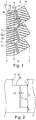
- Fig. 1 three tread blocks 1a, 2a each of two tread block rows 1, 2 running in the middle tread area are shown, the tread blocks 1a, 2a of the two tread block rows 1, 2 lying next to one another in pairs in the axial direction.
- the equatorial plane of the vehicle tire is in Fig. 1 indicated by a line AA and runs through the tread block row 1.
- the tread block rows 1 and 2 jointly occupy a width b 1 in the axial direction of 20% to 35% of the largest ground contact area width of the tread, the ground contact area being the statically determined footprint according to ETRTO standards (Load at 70% of the load capacity at an internal pressure of 2.5 bar, internal pressure 85% of 2.9 bar).
- All profile blocks 1a, 2a are provided with incisions 3, which in each profile block row 1, 2 extend parallel to one another and in plan view at an angle deviating from the axial direction by 15 ° to 25 °.
- the incisions 3 each have a middle section 3a, which is undulating in plan view, and two straight end sections 3b.
- transverse grooves 4 In the circumferential direction successive pairs of side-by-side profile blocks 1a, 2a are separated from one another by transverse grooves 4 continuous over both rows of tread blocks 1, 2, the transverse grooves 4 in the embodiment variant shown in plan view each having a kinked course and therefore a section 4a and a section extending essentially in the axial direction to the axial direction inclined section 4b, which extends at an angle ⁇ deviating from the axial direction by up to 30 °.
- the profile blocks 1a, 2a lying next to one another in pairs are separated from one another by a shallow circumferential groove 5 with a groove base 5a and an incision 6 starting from the center of the groove base 5a ( Fig. 2 ), the circumferential groove 5 and the incision 6 opening with their ends into one of the transverse grooves 4.
- the circumferential grooves 5 and the incisions 6 run straight in plan view and at an angle ⁇ of 0 ° to 30 °, in particular of up to 15 °, and preferably of 0 °, to the circumferential direction.
- the circumferential grooves 5 and the incisions 6 run in such a way that they open with their one end at the kink of the one transverse groove 4 and with their other end into the inclined section 4a of the other transverse groove 4.
- Fig. 2 shows a cross section through a circumferential groove 5, the level of the tread depth provided for the relevant tread, which is usually 6.5 mm to 9.0 mm, is shown in broken lines.
- the circumferential groove 5 is essentially flat U-shaped when viewed in cross section, has a depth T 1 of 1.5 mm to 2.5 mm in the radial direction and a width B 1 at the tread periphery which is 2.0 times up to 3.0 times, in particular up to 2.5 times, the depth T 1 .
- the incisions 6 emanating from the groove base 5a run in cross-section in the radial direction, whereby they end at a distance a 1 determined in the radial direction of up to 2.0 mm above the level of the profile depth and a width B 2 of 0.2 mm 0.7 mm.
- the incisions 3 formed in the profile blocks 1a, 2a can - as in FIG Fig. 1 shown -with their straight end sections 3b extend to the incisions 6 and therefore open into the incisions 6.
- the incisions 3 can extend with their straight end sections 3b as far as the circumferential grooves 5 and end at these - at a corresponding distance in front of the incisions 6.
- the incisions provided in the profile blocks 1a, 2a can run straight or at least in sections in a zigzag or sawtooth shape. Furthermore, the incisions can extend in the axial direction or at a distance of up to 45 ° from the axial direction Direction deviating angle extend. Rows of tread blocks with tread blocks lying next to one another in pairs can also be provided in other areas of the tread.
- the transverse grooves 4, which in the circumferential direction separate successive profile blocks 1a, 2a lying next to one another in pairs, can also run straight or provided with several kinks in plan view.
- the profile blocks 1a, 2a can have any shape in plan view, in particular one that is customary for profile blocks.
Landscapes
- Engineering & Computer Science (AREA)
- Mechanical Engineering (AREA)
- Tires In General (AREA)
Description
- Die Erfindung betrifft einen Fahrzeugluftreifen mit einem Laufstreifen mit zumindest zwei in Umfangsrichtung umlaufenden Profilblockreihen mit in axialer Richtung paarweise nebeneinanderliegenden Profilblöcken, welche durch Querrillen voneinander getrennt sind, wobei die nebeneinanderliegenden Profilblöcke jeweils durch eine im Querschnitt im Wesentlichen U-Förmige Umfangsnut mit einem Nutgrund und einem vom Nutgrund ausgehenden in radialer Richtung verlaufenden Einschnitt voneinander getrennt sind, wobei die Umfangsnuten und die Einschnitte in Draufsicht gerade sowie zur Umfangsrichtung unter einem Winkel von bis zu 30° verlaufen.
- Ein derartiger Fahrzeugluftreifen, welcher für den ganzjährigen Einsatz geeignet sein soll, ist beispielsweise aus der
JP 2001 199206 A - Aus der
EP 2 230 103 A1 ist ein Fahrzeugluftreifen mit einem Laufstreifen mit zwei Profilblockreihen mit in axialer Richtung paarweise nebeneinanderliegenden Profilblöcken, welche durch Querrillen voneinander getrennt sind, bekannt. Die in axialer Richtung paarweise nebeneinanderliegenden Profilblöcke sind durch Umfangsnuten voneinander getrennt, von deren Nutgrund ein Einschnitt ausgeht. Die Einschnitte weisen einen entlang der einen Nutflanke verlaufenden, ersten Erstreckungsbereich, einen entlang der anderen Nutflanke verlaufenden, zweiten Erstreckungsbereich und einen zwischen diesen Erstreckungsbereichen sowie quer zur Erstreckungsrichtung der Umfangsnut verlaufenden Übergangsbereich auf. Diese Maßnahmen sollen - bedingt durch Abstützungseffekte - beim Auftreten hoher Querkräfte einen vergleichsweise geringen Laufstreifenabrieb ermöglichen. - Die
EP 0 841 199 A2 offenbart einen Fahrzeugluftreifen mit einem Laufstreifen mit in axialer Richtung paarweise nebeneinanderliegenden Profilblöcken, welche durch eine unterbrechungsfrei umlaufende Umfangsnut voneinander getrennt sind. Vom Nutgrund der Umfangsnut geht ein umlaufender Einschnitt aus. - Seichtere Umfangsnuten mit von ihrem Nutgrund ausgehenden Einschnitten entkoppeln die paarweise nebeneinanderliegenden Profilblöcke derart, dass ein gleichmäßiger Laufstreifenabriebes unterstützt wird. Die Umfangsnuten des aus der
JP 2001 199206 A - Der Erfindung liegt daher die Aufgabe zugrunde, bei einem Fahrzeugluftreifen der eingangs genannten Art die Performance auf schneebedecktem Untergrund zu verbessern.
- Die gestellte Aufgabe wird erfindungsgemäß dadurch gelöst, dass die Umfangsnuten eine Tiefe von 1,5 mm bis 2,5 mm sowie an der Laufstreifenperipherie eine Breite, welche das 2,0-Fache bis 3,0-Fache der Tiefe beträgt, aufweisen, wobei die Einschnitte in einem in radialer Richtung ermittelten Abstand von bis zu 2,0 mm über dem Niveau der Profiltiefe enden und eine Breite von 0,2 mm bis 0,7 mm aufweisen.
- Gemäß der Erfindung ausgeführte Umfangsnuten, die gemeinsam mit dem von ihrem Nutgrund ausgehenden Einschnitten die paarweise nebeneinanderliegenden Profilblöcke voneinander trennen, sind derart dimensioniert, dass sie einen guten Schneegriff sicherstellen. Die relativ seichten Umfangsnuten füllen sich beim Fahren auf schneebedeckten Fahrbahnen besonders schnell und zuverlässig mit Schnee und gewährleisten die für den Schneegriff wichtige Schnee-Schnee-Reibung zwischen dem Laufstreifen und der schneebedeckten Fahrbahn. Besonders vorteilhaft ist die Schnee-Schnee-Reibung im Bereich dieser Umfangsnuten für eine gute Übertragung von Seitenkräften auf die Fahrbahn bei Kurvenfahrt.
- Gemäß einer bevorzugten Ausführungsform der Erfindung beträgt die Breite der Umfangsnuten an der Laufstreifenperipherie maximal das 2,5-Fache ihrer Tiefe. Nuten mit einem derartigen Verhältnis von Breite zu Tiefe können sich besonders gut und schnell mit Schnee füllen und die erwünschte Schnee-Schnee-Reibung sicherstellen.
- Der Winkel, unter welchem die Umfangsnuten und die Einschnitte in Draufsicht zur Umfangsrichtung verlaufen, beträgt gemäß einer bevorzugten Ausführung der Erfindung bis zu 15°, insbesondere 0°. Ein derartiger Verlauf der Umfangsnuten ist für eine gute Seitenführung auf schneebedeckten Fahrbahnen besonders vorteilhaft.
- Schnee- und Eisgriff von erfindungsgemäß ausgeführten Fahrzeugluftreifen werden ferner, wie an sich bekannt, auch durch eine Vielzahl von schmalen, insbesondere 0,3 mm bis 0,8 mm breiten Einschnitten in den Profilblöcken vorteilhaft beeinflusst. Bei einer bevorzugten Ausführungsform der Erfindung sind daher auch die paarweise nebeneinander liegenden Profilblöcke jeweils mit einer Vielzahl von zur Querrichtung des Laufstreifens unter einem Winkel von bis zu 45° verlaufenden Einschnitten versehen. Solche Einschnitte verlaufen oft in Draufsicht wellenförmig. Bei einer Ausführungsform der Erfindung sind in den Profilblöcken Einschnitte vorgesehen, welche mit insbesondere in Draufsicht gerade verlaufenden Endabschnitten bis zu den Umfangsnuten reichen, daher in diese einmünden, wobei bei einer alternativen, für Schnee- und Eisgriff besonders vorteilhaften Ausführungsform, diese Endabschnitte bis zu den vom Nutgrund der Umfangsnuten ausgehenden Einschnitten reichen.
- Die Profilblockreihen mit den in axialer Richtung paarweise nebeneinanderliegenden Profilblöcken befindet sich bevorzugt im mittleren Bereich des Laufstreifens und weisen in axialer Richtung eine Breite von 20% bis 35% der Bodenaufstandsflächenbreite des Laufstreifens auf. Derart positionierte, nebeneinanderliegende Profilblockreihen sorgen besonders gut für die Übertragung von Seitenkräften auf schneebedeckten Fahrbahnen bei Kurvenfahrt.
- Weitere Merkmale, Vorteile und Einzelheiten der Erfindung werden nun anhand der Zeichnung, die schematisch ein Ausführungsbeispiel der Erfindung zeigt, näher beschrieben. Dabei zeigen
-
Fig. 1 eine Draufsicht auf einen Umfangsabschnitt von zwei nebeneinanderliegende Profilblockreihen eines Laufstreifens eines Fahrzeugluftreifens mit einer Ausführungsvariante der Erfindung und -
Fig. 2 einen Schnitt entlang der Linie II-II derFig. 1 . - Erfindungsgemäß ausgeführte Fahrzeugluftreifen sind Winterreifen oder Ganzjahresreifen in Radialbauart für Personenkraftwagen, Vans oder Light-Trucks.
- In
Fig. 1 sind von zwei im mittleren Laufstreifenbereich in Umfangsrichtung umlaufenden Profilblockreihen 1, 2 jeweils drei Profilblöcke 1a, 2a gezeigt, wobei die Profilblöcke 1a, 2a der beiden Profilblockreihen 1, 2 in axialer Richtung paarweise nebeneinanderliegen. Die Äquatorialebene des Fahrzeugluftreifens ist inFig. 1 durch eine Linie A-A angedeutet und verläuft durch die Profilblockreihe 1. Die Profilblockreihen 1 und 2 nehmen in axialer Richtung gemeinsam eine Breite b1 von 20% bis 35% der größten Bodenaufstandsflächenbreite des Laufstreifens ein, wobei die Bodenaufstandsfläche dem statisch ermittelten Footprint gemäß E.T.R.T.O.-Standards (Last bei 70% der Tragfähigkeit bei einem Innendruck von 2,5 bar, Innendruck 85% von 2,9 bar) entspricht. - Sämtliche Profilblöcke 1a, 2a sind mit Einschnitten 3 versehen, welche sich in jeder Profilblockreihe 1, 2 parallel zueinander sowie in Draufsicht unter einem um 15° bis 25° von der axialen Richtung abweichenden Winkel erstrecken. Die Einschnitte 3 weisen jeweils einen in Draufsicht wellenförmigen mittleren Abschnitt 3a und zwei gerade verlaufende Endabschnitte 3b auf.
- In Umfangsrichtung aufeinanderfolgende paarweise nebeneinanderliegende Profilblöcke 1a, 2a sind durch über beide Profilblockreihen 1, 2 durchgehende Querrillen 4 voneinander getrennt, wobei die Querrillen 4 bei der gezeigten Ausführungsvariante in Draufsicht jeweils einen geknickten Verlauf und daher einen im Wesentlichen in axialer Richtung verlaufenden Abschnitt 4a und einen zur axialen Richtung geneigten Abschnitt 4b, welcher unter einem um bis zu 30° von der axialen Richtung abweichenden Winkel α verläuft, aufweisen.
- Die paarweise nebeneinanderliegenden Profilblöcke 1a, 2a sind voneinander jeweils durch eine seichte Umfangsnut 5 mit einem Nutgrund 5a und einen von der Mitte des Nutgrundes 5a ausgehenden Einschnitt 6 getrennt (
Fig. 2 ), wobei die Umfangsnut 5 und der Einschnitt 6 mit ihren Enden in je eine der Querrillen 4 münden. Die Umfangsnuten 5 und die Einschnitte 6 verlaufen in Draufsicht gerade sowie unter einem Winkel β von 0° bis zu 30°, insbesondere von bis zu 15°, und bevorzugt von 0°, zur Umfangsrichtung. Beim gezeigten Ausführungsbeispiel verlaufen die Umfangsnuten 5 und die Einschnitte 6 derart, dass sie mit ihrem einen Ende beim Knick der einen Querrille 4 und mit ihrem anderen Ende in den geneigten Abschnitt 4a der anderen Querrille 4 einmünden. -
Fig. 2 zeigt einen Querschnitt durch eine Umfangsnut 5, wobei das Niveau der für den betreffenden Laufstreifen vorgesehenen Profiltiefe, welche üblicherweise 6,5 mm bis 9,0 mm beträgt, gestrichelt eingezeichnet ist. Die Umfangsnut 5 ist im Querschnitt betrachtet im Wesentlichen flach U-förmig ausgeführt, weist in radialer Richtung eine Tiefe T1 von 1,5 mm bis 2,5 mm sowie an der Laufstreifenperipherie eine Breite B1 auf, welche das 2,0-Fache bis 3,0-Fache, insbesondere bis zum 2,5-Fachen, der Tiefe T1 beträgt. Die vom Nutgrund 5a ausgehenden Einschnitte 6 verlaufen im Querschnitt betrachtet in radialer Richtung, wobei sie in einem in radialer Richtung ermittelten Abstand a1 von bis zu 2,0 mm über dem Niveau der Profiltiefe enden und eine Breite B2 von 0,2 mm bis 0,7 mm aufweisen. - Die in den Profilblöcken 1a, 2a ausgebildeten Einschnitte 3 können - wie in
Fig. 1 gezeigt -mit ihren gerade verlaufende Endabschnitten 3b bis zu den Einschnitten 6 reichen und daher in die Einschnitte 6 münden. Alternativ können die Einschnitte 3 mit ihren gerade verlaufenden Endabschnitten 3b bis zu den Umfangsnuten 5 verlaufen und an diesen - in einem entsprechenden Abstand vor den Einschnitten 6 - enden. - Die Erfindung ist nicht auf das beschriebene Ausführungsbeispiel beschränkt. Insbesondere können die in den Profilblöcken 1a, 2a vorgesehenen Einschnitte in Draufsicht gerade oder zumindest abschnittsweise zickzack- oder sägezahnförmig verlaufen. Ferner können sich die Einschnitte in axialer Richtung oder unter einem um bis zu 45° von der axialen Richtung abweichenden Winkel erstrecken. Profilblockreihen mit paarweisen nebeneinanderliegenden Profilblöcken können auch in anderen Bereichen des Laufstreifens vorgesehen sein. Die Querrillen 4, welche in Umfangsrichtung aufeinanderfolgende und paarweise nebeneinanderliegende Profilblöcke 1a, 2a voneinander trennen, können in Draufsicht auch gerade oder mit mehreren Knickstellen versehen verlaufen. Die Profilblöcke 1a, 2a können eine in Draufsicht beliebige, insbesondere eine für Profilblöcke übliche, Gestalt aufweisen.
-
- 1, 2,
- Profilblockreihe
- 1a, 2a
- Profilblock
- 3
- Einschnitt
- 3a
- mittlerer Abschnitt
- 3b
- Endabschnitt
- 4
- Querrille
- 4a, 4b
- Abschnitt
- 5
- Umfangsnut
- 5a
- Nutgrund
- 6
- Einschnitt
- A-A
- Linie
- B1, B2
- Breite
- b1
- Breite
- T1, T2
- Tiefe
- A-A
- Linie
- α, β
- Winkel
Claims (7)
- Fahrzeugluftreifen mit einem Laufstreifen mit zumindest zwei in Umfangsrichtung umlaufenden Profilblockreihen (1, 2) mit in axialer Richtung paarweise nebeneinanderliegenden Profilblöcken (la, 2a), welche durch Querrillen (4) voneinander getrennt sind, wobei die nebeneinanderliegenden Profilblöcke (la, 2a) durch eine im Querschnitt im Wesentlichen U-Förmige Umfangsnut (5) mit einem Nutgrund (5a) und einem vom Nutgrund (5a) ausgehenden in radialer Richtung verlaufenden Einschnitt (6) voneinander getrennt sind, wobei die Umfangsnuten (5) und die Einschnitte (6) zur Umfangsrichtung unter einem Winkel (β) von bis zu 30° verlaufen, wobei die Umfangsnuten (5) eine Tiefe (T1) von 1,5 mm bis 2,5 mm aufweisen und wobei die Einschnitte (6) in einem in radialer Richtung ermittelten Abstand (a1) von bis zu 2,0 mm über dem Niveau der Profiltiefe enden und eine Breite (B2) von 0,2 mm bis 0,7 mm aufweisen, dadurch gekennzeichnet,
dass die Umfangsnuten (5) und die Einschnitte (6) in Draufsicht gerade verlaufen und die Umfangsnuten (5) an der Laufstreifenperipherie eine Breite (B1) aufweisen, welche das 2,0-Fache bis 3,0-Fache ihrer Tiefe (T1) beträgt. - Fahrzeugluftreifen nach Anspruch 1, dadurch gekennzeichnet, dass die Breite (B1) der Umfangsnuten (5) an der Laufstreifenperipherie maximal das 2,5-Fache der Tiefe (T1) der Umfangsnuten (5) beträgt.
- Fahrzeugluftreifen nach Anspruch 1 oder 2, dadurch gekennzeichnet, dass der Winkel (β), unter welchem die Umfangsnuten (5) und die Einschnitte (6) in Draufsicht zur Umfangsrichtung verlaufen, bis zu 15°, insbesondere 0°, beträgt.
- Fahrzeugluftreifen nach einem der Ansprüche 1 bis 3, dadurch gekennzeichnet, dass die paarweise nebeneinanderliegenden Profilblöcke (1a, 2a) jeweils mit einer Vielzahl von zur Querrichtung des Laufstreifens unter einem Winkel von bis zu 45° verlaufenden Einschnitten (3) versehen sind, welche mit insbesondere in Draufsicht gerade verlaufenden Endabschnitten (3b) bis zu den Umfangsnuten (5) reichen.
- Fahrzeugluftreifen nach einem der Ansprüche 1 bis 4, dadurch gekennzeichnet, dass die Profilblöcke (1a, 2a) der zumindest zwei Profilblockreihen (1, 2) mit in axialer Richtung paarweise nebeneinanderliegenden Profilblöcken (1a, 2a) jeweils mit einer Vielzahl von zur Querrichtung des Laufstreifens unter einem Winkel von bis zu 45° verlaufenden Einschnitten (3) versehen sind, welche insbesondere mit in Draufsicht geraden Endabschnitten (3b) bis zu den vom Nutgrund (5a) der Umfangsnuten (5) ausgehenden Einschnitten (6) reichen.
- Fahrzeugluftreifen nach einem der Ansprüche 1 bis 5, dadurch gekennzeichnet, dass die zwei Profilblockreihen (1, 2) mit den in axialer Richtung paarweise nebeneinanderliegenden Profilblöcken (1a, 2a) im mittleren Bereich des Laufstreifens verlaufen.
- Fahrzeugluftreifen nach einem der Ansprüche 1 bis 6, dadurch gekennzeichnet, dass die zwei Profilblockreihen (1, 2) mit den in axialer Richtung paarweise nebeneinanderliegenden Profilblöcken (1a, 2a) in axialer Richtung eine Breite (b1) von 20% bis 35% der Bodenaufstandsflächenbreite des Laufstreifens aufweisen.
Applications Claiming Priority (2)
| Application Number | Priority Date | Filing Date | Title |
|---|---|---|---|
| DE102016224366.7A DE102016224366A1 (de) | 2016-12-07 | 2016-12-07 | Fahrzeugluftreifen |
| PCT/EP2017/076040 WO2018103924A1 (de) | 2016-12-07 | 2017-10-12 | Fahrzeugluftreifen |
Publications (2)
| Publication Number | Publication Date |
|---|---|
| EP3551476A1 EP3551476A1 (de) | 2019-10-16 |
| EP3551476B1 true EP3551476B1 (de) | 2020-09-16 |
Family
ID=60080827
Family Applications (1)
| Application Number | Title | Priority Date | Filing Date |
|---|---|---|---|
| EP17783500.6A Active EP3551476B1 (de) | 2016-12-07 | 2017-10-12 | Fahrzeugluftreifen |
Country Status (3)
| Country | Link |
|---|---|
| EP (1) | EP3551476B1 (de) |
| DE (1) | DE102016224366A1 (de) |
| WO (1) | WO2018103924A1 (de) |
Families Citing this family (6)
| Publication number | Priority date | Publication date | Assignee | Title |
|---|---|---|---|---|
| DE102020215799A1 (de) | 2020-12-14 | 2022-06-15 | Continental Reifen Deutschland Gmbh | Fahrzeugluftreifen mit mittiger Umfangsrippe |
| EP4043245B1 (de) * | 2021-02-12 | 2024-06-26 | Sumitomo Rubber Industries, Ltd. | Reifen |
| FR3134036B1 (fr) * | 2022-04-05 | 2024-07-12 | Michelin & Cie | Pneumatique comportant une bande de roulement recreusable |
| DE102022211346A1 (de) * | 2022-10-26 | 2024-05-02 | Continental Reifen Deutschland Gmbh | Fahrzeugluftreifen |
| FR3150990B1 (fr) * | 2023-07-11 | 2026-01-02 | Michelin & Cie | Pneumatique comportant une bande de roulement recreusable |
| EP4552861A1 (de) * | 2023-11-13 | 2025-05-14 | Bridgestone Europe NV/SA | Reifen mit verbessertem laufflächenprofil |
Family Cites Families (6)
| Publication number | Priority date | Publication date | Assignee | Title |
|---|---|---|---|---|
| JP3136101B2 (ja) * | 1996-09-19 | 2001-02-19 | 住友ゴム工業株式会社 | 空気入りタイヤ |
| JP4573984B2 (ja) | 1999-11-10 | 2010-11-04 | 住友ゴム工業株式会社 | 空気入りラジアルタイヤ |
| JP4475756B2 (ja) * | 2000-07-12 | 2010-06-09 | 株式会社ブリヂストン | 空気入りタイヤ |
| DE102009003642A1 (de) * | 2009-03-19 | 2010-09-23 | Continental Reifen Deutschland Gmbh | Laufflächenprofil eines Fahrzeugluftreifens |
| DE102010060945A1 (de) * | 2010-12-01 | 2012-06-06 | Continental Reifen Deutschland Gmbh | Fahrzeugluftreifen |
| JP6169326B2 (ja) * | 2012-05-28 | 2017-07-26 | 株式会社ブリヂストン | 空気入りタイヤ |
-
2016
- 2016-12-07 DE DE102016224366.7A patent/DE102016224366A1/de not_active Withdrawn
-
2017
- 2017-10-12 WO PCT/EP2017/076040 patent/WO2018103924A1/de not_active Ceased
- 2017-10-12 EP EP17783500.6A patent/EP3551476B1/de active Active
Non-Patent Citations (1)
| Title |
|---|
| None * |
Also Published As
| Publication number | Publication date |
|---|---|
| DE102016224366A1 (de) | 2018-06-07 |
| EP3551476A1 (de) | 2019-10-16 |
| WO2018103924A1 (de) | 2018-06-14 |
Similar Documents
| Publication | Publication Date | Title |
|---|---|---|
| EP3551476B1 (de) | Fahrzeugluftreifen | |
| EP2920007B1 (de) | Fahrzeugluftreifen | |
| EP2646263B1 (de) | Fahrzeugluftreifen | |
| EP2965925B1 (de) | Fahrzeugluftreifen | |
| EP0729854B1 (de) | Fahrzeugreifen | |
| EP2353884B1 (de) | Fahrzeugluftreifen | |
| EP2460672B1 (de) | Fahrzeugluftreifen | |
| EP2159080B1 (de) | Fahrzeugluftreifen | |
| EP3645318B1 (de) | Fahrzeugluftreifen | |
| EP3383669B1 (de) | Fahrzeugluftreifen | |
| EP3300926B1 (de) | Fahrzeugluftreifen | |
| EP3421264B1 (de) | Fahrzeugluftreifen | |
| EP4347277B1 (de) | Fahrzeugluftreifen | |
| EP2465708B1 (de) | Fahrzeugluftreifen | |
| EP2217455B1 (de) | Fahrzeugluftreifen | |
| EP3717281B1 (de) | Fahrzeugluftreifen | |
| EP3383675B1 (de) | Fahrzeugluftreifen | |
| EP3659825B1 (de) | Fahrzeugluftreifen | |
| EP3446892B1 (de) | Fahrzeugluftreifen | |
| EP3551477B1 (de) | Fahrzeugluftreifen | |
| EP3045326B1 (de) | Fahrzeugluftreifen | |
| EP3034331B1 (de) | Fahrzeugluftreifen | |
| EP3079925B1 (de) | Fahrzeugluftreifen | |
| EP3300925B1 (de) | Fahrzeugluftreifen | |
| EP3173253B1 (de) | Fahrzeugluftreifen |
Legal Events
| Date | Code | Title | Description |
|---|---|---|---|
| STAA | Information on the status of an ep patent application or granted ep patent |
Free format text: STATUS: UNKNOWN |
|
| STAA | Information on the status of an ep patent application or granted ep patent |
Free format text: STATUS: THE INTERNATIONAL PUBLICATION HAS BEEN MADE |
|
| PUAI | Public reference made under article 153(3) epc to a published international application that has entered the european phase |
Free format text: ORIGINAL CODE: 0009012 |
|
| STAA | Information on the status of an ep patent application or granted ep patent |
Free format text: STATUS: REQUEST FOR EXAMINATION WAS MADE |
|
| 17P | Request for examination filed |
Effective date: 20190708 |
|
| AK | Designated contracting states |
Kind code of ref document: A1 Designated state(s): AL AT BE BG CH CY CZ DE DK EE ES FI FR GB GR HR HU IE IS IT LI LT LU LV MC MK MT NL NO PL PT RO RS SE SI SK SM TR |
|
| AX | Request for extension of the european patent |
Extension state: BA ME |
|
| DAV | Request for validation of the european patent (deleted) | ||
| DAX | Request for extension of the european patent (deleted) | ||
| GRAP | Despatch of communication of intention to grant a patent |
Free format text: ORIGINAL CODE: EPIDOSNIGR1 |
|
| STAA | Information on the status of an ep patent application or granted ep patent |
Free format text: STATUS: GRANT OF PATENT IS INTENDED |
|
| INTG | Intention to grant announced |
Effective date: 20200603 |
|
| RIN1 | Information on inventor provided before grant (corrected) |
Inventor name: KRINGS, STEFAN Inventor name: BRANDAU, CHRISTIAN Inventor name: SENG, MATTHIAS |
|
| GRAS | Grant fee paid |
Free format text: ORIGINAL CODE: EPIDOSNIGR3 |
|
| GRAA | (expected) grant |
Free format text: ORIGINAL CODE: 0009210 |
|
| STAA | Information on the status of an ep patent application or granted ep patent |
Free format text: STATUS: THE PATENT HAS BEEN GRANTED |
|
| AK | Designated contracting states |
Kind code of ref document: B1 Designated state(s): AL AT BE BG CH CY CZ DE DK EE ES FI FR GB GR HR HU IE IS IT LI LT LU LV MC MK MT NL NO PL PT RO RS SE SI SK SM TR |
|
| REG | Reference to a national code |
Ref country code: GB Ref legal event code: FG4D Free format text: NOT ENGLISH |
|
| REG | Reference to a national code |
Ref country code: CH Ref legal event code: EP |
|
| REG | Reference to a national code |
Ref country code: DE Ref legal event code: R096 Ref document number: 502017007324 Country of ref document: DE |
|
| REG | Reference to a national code |
Ref country code: IE Ref legal event code: FG4D Free format text: LANGUAGE OF EP DOCUMENT: GERMAN |
|
| REG | Reference to a national code |
Ref country code: AT Ref legal event code: REF Ref document number: 1313829 Country of ref document: AT Kind code of ref document: T Effective date: 20201015 |
|
| RAP2 | Party data changed (patent owner data changed or rights of a patent transferred) |
Owner name: CONTINENTAL REIFEN DEUTSCHLAND GMBH |
|
| PG25 | Lapsed in a contracting state [announced via postgrant information from national office to epo] |
Ref country code: HR Free format text: LAPSE BECAUSE OF FAILURE TO SUBMIT A TRANSLATION OF THE DESCRIPTION OR TO PAY THE FEE WITHIN THE PRESCRIBED TIME-LIMIT Effective date: 20200916 Ref country code: SE Free format text: LAPSE BECAUSE OF FAILURE TO SUBMIT A TRANSLATION OF THE DESCRIPTION OR TO PAY THE FEE WITHIN THE PRESCRIBED TIME-LIMIT Effective date: 20200916 Ref country code: GR Free format text: LAPSE BECAUSE OF FAILURE TO SUBMIT A TRANSLATION OF THE DESCRIPTION OR TO PAY THE FEE WITHIN THE PRESCRIBED TIME-LIMIT Effective date: 20201217 Ref country code: FI Free format text: LAPSE BECAUSE OF FAILURE TO SUBMIT A TRANSLATION OF THE DESCRIPTION OR TO PAY THE FEE WITHIN THE PRESCRIBED TIME-LIMIT Effective date: 20200916 Ref country code: BG Free format text: LAPSE BECAUSE OF FAILURE TO SUBMIT A TRANSLATION OF THE DESCRIPTION OR TO PAY THE FEE WITHIN THE PRESCRIBED TIME-LIMIT Effective date: 20201216 |
|
| REG | Reference to a national code |
Ref country code: NO Ref legal event code: T2 Effective date: 20200916 |
|
| REG | Reference to a national code |
Ref country code: NL Ref legal event code: MP Effective date: 20200916 |
|
| PG25 | Lapsed in a contracting state [announced via postgrant information from national office to epo] |
Ref country code: LV Free format text: LAPSE BECAUSE OF FAILURE TO SUBMIT A TRANSLATION OF THE DESCRIPTION OR TO PAY THE FEE WITHIN THE PRESCRIBED TIME-LIMIT Effective date: 20200916 Ref country code: RS Free format text: LAPSE BECAUSE OF FAILURE TO SUBMIT A TRANSLATION OF THE DESCRIPTION OR TO PAY THE FEE WITHIN THE PRESCRIBED TIME-LIMIT Effective date: 20200916 |
|
| REG | Reference to a national code |
Ref country code: LT Ref legal event code: MG4D |
|
| PG25 | Lapsed in a contracting state [announced via postgrant information from national office to epo] |
Ref country code: LT Free format text: LAPSE BECAUSE OF FAILURE TO SUBMIT A TRANSLATION OF THE DESCRIPTION OR TO PAY THE FEE WITHIN THE PRESCRIBED TIME-LIMIT Effective date: 20200916 Ref country code: SM Free format text: LAPSE BECAUSE OF FAILURE TO SUBMIT A TRANSLATION OF THE DESCRIPTION OR TO PAY THE FEE WITHIN THE PRESCRIBED TIME-LIMIT Effective date: 20200916 Ref country code: EE Free format text: LAPSE BECAUSE OF FAILURE TO SUBMIT A TRANSLATION OF THE DESCRIPTION OR TO PAY THE FEE WITHIN THE PRESCRIBED TIME-LIMIT Effective date: 20200916 Ref country code: PT Free format text: LAPSE BECAUSE OF FAILURE TO SUBMIT A TRANSLATION OF THE DESCRIPTION OR TO PAY THE FEE WITHIN THE PRESCRIBED TIME-LIMIT Effective date: 20210118 Ref country code: RO Free format text: LAPSE BECAUSE OF FAILURE TO SUBMIT A TRANSLATION OF THE DESCRIPTION OR TO PAY THE FEE WITHIN THE PRESCRIBED TIME-LIMIT Effective date: 20200916 Ref country code: CZ Free format text: LAPSE BECAUSE OF FAILURE TO SUBMIT A TRANSLATION OF THE DESCRIPTION OR TO PAY THE FEE WITHIN THE PRESCRIBED TIME-LIMIT Effective date: 20200916 |
|
| PG25 | Lapsed in a contracting state [announced via postgrant information from national office to epo] |
Ref country code: IS Free format text: LAPSE BECAUSE OF FAILURE TO SUBMIT A TRANSLATION OF THE DESCRIPTION OR TO PAY THE FEE WITHIN THE PRESCRIBED TIME-LIMIT Effective date: 20210116 Ref country code: PL Free format text: LAPSE BECAUSE OF FAILURE TO SUBMIT A TRANSLATION OF THE DESCRIPTION OR TO PAY THE FEE WITHIN THE PRESCRIBED TIME-LIMIT Effective date: 20200916 Ref country code: ES Free format text: LAPSE BECAUSE OF FAILURE TO SUBMIT A TRANSLATION OF THE DESCRIPTION OR TO PAY THE FEE WITHIN THE PRESCRIBED TIME-LIMIT Effective date: 20200916 Ref country code: AL Free format text: LAPSE BECAUSE OF FAILURE TO SUBMIT A TRANSLATION OF THE DESCRIPTION OR TO PAY THE FEE WITHIN THE PRESCRIBED TIME-LIMIT Effective date: 20200916 |
|
| REG | Reference to a national code |
Ref country code: CH Ref legal event code: PL |
|
| REG | Reference to a national code |
Ref country code: DE Ref legal event code: R097 Ref document number: 502017007324 Country of ref document: DE |
|
| PG25 | Lapsed in a contracting state [announced via postgrant information from national office to epo] |
Ref country code: LU Free format text: LAPSE BECAUSE OF NON-PAYMENT OF DUE FEES Effective date: 20201012 Ref country code: SK Free format text: LAPSE BECAUSE OF FAILURE TO SUBMIT A TRANSLATION OF THE DESCRIPTION OR TO PAY THE FEE WITHIN THE PRESCRIBED TIME-LIMIT Effective date: 20200916 Ref country code: MC Free format text: LAPSE BECAUSE OF FAILURE TO SUBMIT A TRANSLATION OF THE DESCRIPTION OR TO PAY THE FEE WITHIN THE PRESCRIBED TIME-LIMIT Effective date: 20200916 |
|
| REG | Reference to a national code |
Ref country code: BE Ref legal event code: MM Effective date: 20201031 |
|
| PLBE | No opposition filed within time limit |
Free format text: ORIGINAL CODE: 0009261 |
|
| STAA | Information on the status of an ep patent application or granted ep patent |
Free format text: STATUS: NO OPPOSITION FILED WITHIN TIME LIMIT |
|
| 26N | No opposition filed |
Effective date: 20210617 |
|
| PG25 | Lapsed in a contracting state [announced via postgrant information from national office to epo] |
Ref country code: CH Free format text: LAPSE BECAUSE OF NON-PAYMENT OF DUE FEES Effective date: 20201031 Ref country code: BE Free format text: LAPSE BECAUSE OF NON-PAYMENT OF DUE FEES Effective date: 20201031 Ref country code: SI Free format text: LAPSE BECAUSE OF FAILURE TO SUBMIT A TRANSLATION OF THE DESCRIPTION OR TO PAY THE FEE WITHIN THE PRESCRIBED TIME-LIMIT Effective date: 20200916 Ref country code: DK Free format text: LAPSE BECAUSE OF FAILURE TO SUBMIT A TRANSLATION OF THE DESCRIPTION OR TO PAY THE FEE WITHIN THE PRESCRIBED TIME-LIMIT Effective date: 20200916 Ref country code: LI Free format text: LAPSE BECAUSE OF NON-PAYMENT OF DUE FEES Effective date: 20201031 |
|
| PG25 | Lapsed in a contracting state [announced via postgrant information from national office to epo] |
Ref country code: IT Free format text: LAPSE BECAUSE OF FAILURE TO SUBMIT A TRANSLATION OF THE DESCRIPTION OR TO PAY THE FEE WITHIN THE PRESCRIBED TIME-LIMIT Effective date: 20200916 Ref country code: IE Free format text: LAPSE BECAUSE OF NON-PAYMENT OF DUE FEES Effective date: 20201012 Ref country code: FR Free format text: LAPSE BECAUSE OF NON-PAYMENT OF DUE FEES Effective date: 20201116 |
|
| PG25 | Lapsed in a contracting state [announced via postgrant information from national office to epo] |
Ref country code: TR Free format text: LAPSE BECAUSE OF FAILURE TO SUBMIT A TRANSLATION OF THE DESCRIPTION OR TO PAY THE FEE WITHIN THE PRESCRIBED TIME-LIMIT Effective date: 20200916 Ref country code: MT Free format text: LAPSE BECAUSE OF FAILURE TO SUBMIT A TRANSLATION OF THE DESCRIPTION OR TO PAY THE FEE WITHIN THE PRESCRIBED TIME-LIMIT Effective date: 20200916 Ref country code: CY Free format text: LAPSE BECAUSE OF FAILURE TO SUBMIT A TRANSLATION OF THE DESCRIPTION OR TO PAY THE FEE WITHIN THE PRESCRIBED TIME-LIMIT Effective date: 20200916 |
|
| GBPC | Gb: european patent ceased through non-payment of renewal fee |
Effective date: 20211012 |
|
| PG25 | Lapsed in a contracting state [announced via postgrant information from national office to epo] |
Ref country code: MK Free format text: LAPSE BECAUSE OF FAILURE TO SUBMIT A TRANSLATION OF THE DESCRIPTION OR TO PAY THE FEE WITHIN THE PRESCRIBED TIME-LIMIT Effective date: 20200916 |
|
| PG25 | Lapsed in a contracting state [announced via postgrant information from national office to epo] |
Ref country code: GB Free format text: LAPSE BECAUSE OF NON-PAYMENT OF DUE FEES Effective date: 20211012 |
|
| PG25 | Lapsed in a contracting state [announced via postgrant information from national office to epo] |
Ref country code: NL Free format text: LAPSE BECAUSE OF NON-PAYMENT OF DUE FEES Effective date: 20200923 |
|
| REG | Reference to a national code |
Ref country code: AT Ref legal event code: MM01 Ref document number: 1313829 Country of ref document: AT Kind code of ref document: T Effective date: 20221012 |
|
| PG25 | Lapsed in a contracting state [announced via postgrant information from national office to epo] |
Ref country code: AT Free format text: LAPSE BECAUSE OF NON-PAYMENT OF DUE FEES Effective date: 20221012 |
|
| REG | Reference to a national code |
Ref country code: DE Ref legal event code: R081 Ref document number: 502017007324 Country of ref document: DE Owner name: CONTINENTAL REIFEN DEUTSCHLAND GMBH, DE Free format text: FORMER OWNER: CONTINENTAL REIFEN DEUTSCHLAND GMBH, 30165 HANNOVER, DE |
|
| PGFP | Annual fee paid to national office [announced via postgrant information from national office to epo] |
Ref country code: DE Payment date: 20251031 Year of fee payment: 9 |
|
| PGFP | Annual fee paid to national office [announced via postgrant information from national office to epo] |
Ref country code: NO Payment date: 20251024 Year of fee payment: 9 |