EP3551425B1 - Dreidimensionales formen von gegenständen mit polymeren mit hoher schmelztemperatur - Google Patents
Dreidimensionales formen von gegenständen mit polymeren mit hoher schmelztemperatur Download PDFInfo
- Publication number
- EP3551425B1 EP3551425B1 EP17906582.6A EP17906582A EP3551425B1 EP 3551425 B1 EP3551425 B1 EP 3551425B1 EP 17906582 A EP17906582 A EP 17906582A EP 3551425 B1 EP3551425 B1 EP 3551425B1
- Authority
- EP
- European Patent Office
- Prior art keywords
- layer
- temperature
- polymer particles
- fusing agent
- heat
- Prior art date
- Legal status (The legal status is an assumption and is not a legal conclusion. Google has not performed a legal analysis and makes no representation as to the accuracy of the status listed.)
- Active
Links
- 229920000642 polymer Polymers 0.000 title claims description 165
- 230000008018 melting Effects 0.000 title claims description 51
- 238000002844 melting Methods 0.000 title claims description 51
- 239000002245 particle Substances 0.000 claims description 117
- 239000012530 fluid Substances 0.000 claims description 35
- 238000000034 method Methods 0.000 claims description 26
- 230000005855 radiation Effects 0.000 claims description 25
- 239000000463 material Substances 0.000 claims description 24
- 238000010438 heat treatment Methods 0.000 claims description 18
- 238000007711 solidification Methods 0.000 claims description 12
- 230000008023 solidification Effects 0.000 claims description 12
- 238000000151 deposition Methods 0.000 claims description 5
- 238000006073 displacement reaction Methods 0.000 claims description 4
- 229920006126 semicrystalline polymer Polymers 0.000 claims description 2
- 239000003795 chemical substances by application Substances 0.000 description 61
- 238000009826 distribution Methods 0.000 description 15
- 229910052751 metal Inorganic materials 0.000 description 12
- 239000002184 metal Substances 0.000 description 12
- 239000002904 solvent Substances 0.000 description 10
- 238000001816 cooling Methods 0.000 description 9
- 238000000059 patterning Methods 0.000 description 9
- 238000010146 3D printing Methods 0.000 description 8
- 238000003754 machining Methods 0.000 description 8
- 238000000465 moulding Methods 0.000 description 8
- 230000008901 benefit Effects 0.000 description 6
- 239000000203 mixture Substances 0.000 description 6
- 238000012360 testing method Methods 0.000 description 6
- 238000009835 boiling Methods 0.000 description 5
- 238000013461 design Methods 0.000 description 5
- 238000005516 engineering process Methods 0.000 description 5
- 230000035882 stress Effects 0.000 description 5
- 239000004696 Poly ether ether ketone Substances 0.000 description 4
- 238000013459 approach Methods 0.000 description 4
- 238000010586 diagram Methods 0.000 description 4
- 239000007789 gas Substances 0.000 description 4
- 239000007788 liquid Substances 0.000 description 4
- 229920002530 polyetherether ketone Polymers 0.000 description 4
- 238000007639 printing Methods 0.000 description 4
- 230000008569 process Effects 0.000 description 4
- 230000007480 spreading Effects 0.000 description 4
- 238000003892 spreading Methods 0.000 description 4
- XLYOFNOQVPJJNP-UHFFFAOYSA-N water Substances O XLYOFNOQVPJJNP-UHFFFAOYSA-N 0.000 description 4
- PEDCQBHIVMGVHV-UHFFFAOYSA-N Glycerine Chemical compound OCC(O)CO PEDCQBHIVMGVHV-UHFFFAOYSA-N 0.000 description 3
- 229920000106 Liquid crystal polymer Polymers 0.000 description 3
- 239000004977 Liquid-crystal polymers (LCPs) Substances 0.000 description 3
- JUPQTSLXMOCDHR-UHFFFAOYSA-N benzene-1,4-diol;bis(4-fluorophenyl)methanone Chemical compound OC1=CC=C(O)C=C1.C1=CC(F)=CC=C1C(=O)C1=CC=C(F)C=C1 JUPQTSLXMOCDHR-UHFFFAOYSA-N 0.000 description 3
- 230000008021 deposition Effects 0.000 description 3
- 238000011161 development Methods 0.000 description 3
- 238000000113 differential scanning calorimetry Methods 0.000 description 3
- 238000001035 drying Methods 0.000 description 3
- 230000005670 electromagnetic radiation Effects 0.000 description 3
- 230000004907 flux Effects 0.000 description 3
- 230000006870 function Effects 0.000 description 3
- 239000004812 Fluorinated ethylene propylene Substances 0.000 description 2
- 229920002302 Nylon 6,6 Polymers 0.000 description 2
- 239000004813 Perfluoroalkoxy alkane Substances 0.000 description 2
- 239000004734 Polyphenylene sulfide Substances 0.000 description 2
- 229910000831 Steel Inorganic materials 0.000 description 2
- 238000002835 absorbance Methods 0.000 description 2
- 238000009825 accumulation Methods 0.000 description 2
- 229910052782 aluminium Inorganic materials 0.000 description 2
- XAGFODPZIPBFFR-UHFFFAOYSA-N aluminium Chemical compound [Al] XAGFODPZIPBFFR-UHFFFAOYSA-N 0.000 description 2
- 230000002902 bimodal effect Effects 0.000 description 2
- 230000008859 change Effects 0.000 description 2
- 230000001419 dependent effect Effects 0.000 description 2
- 239000000975 dye Substances 0.000 description 2
- 238000001704 evaporation Methods 0.000 description 2
- -1 for example Substances 0.000 description 2
- 239000003906 humectant Substances 0.000 description 2
- 230000003993 interaction Effects 0.000 description 2
- 230000000873 masking effect Effects 0.000 description 2
- 229920009441 perflouroethylene propylene Polymers 0.000 description 2
- 229920011301 perfluoro alkoxyl alkane Polymers 0.000 description 2
- 239000000049 pigment Substances 0.000 description 2
- 229920001652 poly(etherketoneketone) Polymers 0.000 description 2
- 229920006260 polyaryletherketone Polymers 0.000 description 2
- 229920000069 polyphenylene sulfide Polymers 0.000 description 2
- 229920006375 polyphtalamide Polymers 0.000 description 2
- 229920001343 polytetrafluoroethylene Polymers 0.000 description 2
- 239000010959 steel Substances 0.000 description 2
- 239000000126 substance Substances 0.000 description 2
- 239000000758 substrate Substances 0.000 description 2
- 230000007704 transition Effects 0.000 description 2
- FWLHAQYOFMQTHQ-UHFFFAOYSA-N 2-N-[8-[[8-(4-aminoanilino)-10-phenylphenazin-10-ium-2-yl]amino]-10-phenylphenazin-10-ium-2-yl]-8-N,10-diphenylphenazin-10-ium-2,8-diamine hydroxy-oxido-dioxochromium Chemical compound O[Cr]([O-])(=O)=O.O[Cr]([O-])(=O)=O.O[Cr]([O-])(=O)=O.Nc1ccc(Nc2ccc3nc4ccc(Nc5ccc6nc7ccc(Nc8ccc9nc%10ccc(Nc%11ccccc%11)cc%10[n+](-c%10ccccc%10)c9c8)cc7[n+](-c7ccccc7)c6c5)cc4[n+](-c4ccccc4)c3c2)cc1 FWLHAQYOFMQTHQ-UHFFFAOYSA-N 0.000 description 1
- OKTJSMMVPCPJKN-UHFFFAOYSA-N Carbon Chemical compound [C] OKTJSMMVPCPJKN-UHFFFAOYSA-N 0.000 description 1
- 239000004952 Polyamide Substances 0.000 description 1
- 239000004954 Polyphthalamide Substances 0.000 description 1
- 238000012356 Product development Methods 0.000 description 1
- 229910052775 Thulium Inorganic materials 0.000 description 1
- RTAQQCXQSZGOHL-UHFFFAOYSA-N Titanium Chemical compound [Ti] RTAQQCXQSZGOHL-UHFFFAOYSA-N 0.000 description 1
- 229920013651 Zenite Polymers 0.000 description 1
- 238000010521 absorption reaction Methods 0.000 description 1
- 239000000654 additive Substances 0.000 description 1
- 230000000996 additive effect Effects 0.000 description 1
- 238000000137 annealing Methods 0.000 description 1
- PYKYMHQGRFAEBM-UHFFFAOYSA-N anthraquinone Natural products CCC(=O)c1c(O)c2C(=O)C3C(C=CC=C3O)C(=O)c2cc1CC(=O)OC PYKYMHQGRFAEBM-UHFFFAOYSA-N 0.000 description 1
- 150000004056 anthraquinones Chemical class 0.000 description 1
- QVGXLLKOCUKJST-UHFFFAOYSA-N atomic oxygen Chemical compound [O] QVGXLLKOCUKJST-UHFFFAOYSA-N 0.000 description 1
- 230000015572 biosynthetic process Effects 0.000 description 1
- 239000006229 carbon black Substances 0.000 description 1
- 238000005266 casting Methods 0.000 description 1
- 230000015556 catabolic process Effects 0.000 description 1
- 239000002738 chelating agent Substances 0.000 description 1
- 239000003086 colorant Substances 0.000 description 1
- 239000002131 composite material Substances 0.000 description 1
- 238000000354 decomposition reaction Methods 0.000 description 1
- 238000006731 degradation reaction Methods 0.000 description 1
- 239000003599 detergent Substances 0.000 description 1
- VPXSRGLTQINCRV-UHFFFAOYSA-N dicesium;dioxido(dioxo)tungsten Chemical compound [Cs+].[Cs+].[O-][W]([O-])(=O)=O VPXSRGLTQINCRV-UHFFFAOYSA-N 0.000 description 1
- 230000000694 effects Effects 0.000 description 1
- HQQADJVZYDDRJT-UHFFFAOYSA-N ethene;prop-1-ene Chemical group C=C.CC=C HQQADJVZYDDRJT-UHFFFAOYSA-N 0.000 description 1
- 238000002474 experimental method Methods 0.000 description 1
- 238000009472 formulation Methods 0.000 description 1
- 230000004927 fusion Effects 0.000 description 1
- 238000007499 fusion processing Methods 0.000 description 1
- 239000011521 glass Substances 0.000 description 1
- 229910002804 graphite Inorganic materials 0.000 description 1
- 239000010439 graphite Substances 0.000 description 1
- 230000001771 impaired effect Effects 0.000 description 1
- 239000012212 insulator Substances 0.000 description 1
- 150000002500 ions Chemical class 0.000 description 1
- WTFXARWRTYJXII-UHFFFAOYSA-N iron(2+);iron(3+);oxygen(2-) Chemical compound [O-2].[O-2].[O-2].[O-2].[Fe+2].[Fe+3].[Fe+3] WTFXARWRTYJXII-UHFFFAOYSA-N 0.000 description 1
- SZVJSHCCFOBDDC-UHFFFAOYSA-N iron(II,III) oxide Inorganic materials O=[Fe]O[Fe]O[Fe]=O SZVJSHCCFOBDDC-UHFFFAOYSA-N 0.000 description 1
- 230000001678 irradiating effect Effects 0.000 description 1
- 239000004973 liquid crystal related substance Substances 0.000 description 1
- 238000012423 maintenance Methods 0.000 description 1
- 238000005259 measurement Methods 0.000 description 1
- 230000007246 mechanism Effects 0.000 description 1
- 150000002739 metals Chemical class 0.000 description 1
- 238000009740 moulding (composite fabrication) Methods 0.000 description 1
- 230000003647 oxidation Effects 0.000 description 1
- 238000007254 oxidation reaction Methods 0.000 description 1
- 229910052760 oxygen Inorganic materials 0.000 description 1
- 239000001301 oxygen Substances 0.000 description 1
- 239000003002 pH adjusting agent Substances 0.000 description 1
- 210000002381 plasma Anatomy 0.000 description 1
- BASFCYQUMIYNBI-UHFFFAOYSA-N platinum Chemical compound [Pt] BASFCYQUMIYNBI-UHFFFAOYSA-N 0.000 description 1
- 229920002647 polyamide Polymers 0.000 description 1
- 229920000767 polyaniline Polymers 0.000 description 1
- 239000004810 polytetrafluoroethylene Substances 0.000 description 1
- 238000012545 processing Methods 0.000 description 1
- 239000003380 propellant Substances 0.000 description 1
- 238000010791 quenching Methods 0.000 description 1
- 230000000171 quenching effect Effects 0.000 description 1
- 238000005295 random walk Methods 0.000 description 1
- 230000009467 reduction Effects 0.000 description 1
- 239000007787 solid Substances 0.000 description 1
- 239000011343 solid material Substances 0.000 description 1
- 238000001228 spectrum Methods 0.000 description 1
- 230000003068 static effect Effects 0.000 description 1
- 238000009864 tensile test Methods 0.000 description 1
- 230000008646 thermal stress Effects 0.000 description 1
- 239000010936 titanium Substances 0.000 description 1
- 229910052719 titanium Inorganic materials 0.000 description 1
- 238000012546 transfer Methods 0.000 description 1
- 238000010200 validation analysis Methods 0.000 description 1
- 239000002699 waste material Substances 0.000 description 1
- PGNWIWKMXVDXHP-UHFFFAOYSA-L zinc;1,3-benzothiazole-2-thiolate Chemical compound [Zn+2].C1=CC=C2SC([S-])=NC2=C1.C1=CC=C2SC([S-])=NC2=C1 PGNWIWKMXVDXHP-UHFFFAOYSA-L 0.000 description 1
Images

Classifications
-
- B—PERFORMING OPERATIONS; TRANSPORTING
- B29—WORKING OF PLASTICS; WORKING OF SUBSTANCES IN A PLASTIC STATE IN GENERAL
- B29C—SHAPING OR JOINING OF PLASTICS; SHAPING OF MATERIAL IN A PLASTIC STATE, NOT OTHERWISE PROVIDED FOR; AFTER-TREATMENT OF THE SHAPED PRODUCTS, e.g. REPAIRING
- B29C64/00—Additive manufacturing, i.e. manufacturing of three-dimensional [3D] objects by additive deposition, additive agglomeration or additive layering, e.g. by 3D printing, stereolithography or selective laser sintering
- B29C64/10—Processes of additive manufacturing
- B29C64/165—Processes of additive manufacturing using a combination of solid and fluid materials, e.g. a powder selectively bound by a liquid binder, catalyst, inhibitor or energy absorber
-
- B—PERFORMING OPERATIONS; TRANSPORTING
- B29—WORKING OF PLASTICS; WORKING OF SUBSTANCES IN A PLASTIC STATE IN GENERAL
- B29C—SHAPING OR JOINING OF PLASTICS; SHAPING OF MATERIAL IN A PLASTIC STATE, NOT OTHERWISE PROVIDED FOR; AFTER-TREATMENT OF THE SHAPED PRODUCTS, e.g. REPAIRING
- B29C64/00—Additive manufacturing, i.e. manufacturing of three-dimensional [3D] objects by additive deposition, additive agglomeration or additive layering, e.g. by 3D printing, stereolithography or selective laser sintering
- B29C64/20—Apparatus for additive manufacturing; Details thereof or accessories therefor
- B29C64/205—Means for applying layers
- B29C64/209—Heads; Nozzles
-
- B—PERFORMING OPERATIONS; TRANSPORTING
- B29—WORKING OF PLASTICS; WORKING OF SUBSTANCES IN A PLASTIC STATE IN GENERAL
- B29C—SHAPING OR JOINING OF PLASTICS; SHAPING OF MATERIAL IN A PLASTIC STATE, NOT OTHERWISE PROVIDED FOR; AFTER-TREATMENT OF THE SHAPED PRODUCTS, e.g. REPAIRING
- B29C64/00—Additive manufacturing, i.e. manufacturing of three-dimensional [3D] objects by additive deposition, additive agglomeration or additive layering, e.g. by 3D printing, stereolithography or selective laser sintering
- B29C64/20—Apparatus for additive manufacturing; Details thereof or accessories therefor
- B29C64/264—Arrangements for irradiation
- B29C64/268—Arrangements for irradiation using laser beams; using electron beams [EB]
-
- B—PERFORMING OPERATIONS; TRANSPORTING
- B29—WORKING OF PLASTICS; WORKING OF SUBSTANCES IN A PLASTIC STATE IN GENERAL
- B29C—SHAPING OR JOINING OF PLASTICS; SHAPING OF MATERIAL IN A PLASTIC STATE, NOT OTHERWISE PROVIDED FOR; AFTER-TREATMENT OF THE SHAPED PRODUCTS, e.g. REPAIRING
- B29C64/00—Additive manufacturing, i.e. manufacturing of three-dimensional [3D] objects by additive deposition, additive agglomeration or additive layering, e.g. by 3D printing, stereolithography or selective laser sintering
- B29C64/20—Apparatus for additive manufacturing; Details thereof or accessories therefor
- B29C64/295—Heating elements
-
- B—PERFORMING OPERATIONS; TRANSPORTING
- B29—WORKING OF PLASTICS; WORKING OF SUBSTANCES IN A PLASTIC STATE IN GENERAL
- B29C—SHAPING OR JOINING OF PLASTICS; SHAPING OF MATERIAL IN A PLASTIC STATE, NOT OTHERWISE PROVIDED FOR; AFTER-TREATMENT OF THE SHAPED PRODUCTS, e.g. REPAIRING
- B29C64/00—Additive manufacturing, i.e. manufacturing of three-dimensional [3D] objects by additive deposition, additive agglomeration or additive layering, e.g. by 3D printing, stereolithography or selective laser sintering
- B29C64/30—Auxiliary operations or equipment
- B29C64/307—Handling of material to be used in additive manufacturing
- B29C64/321—Feeding
- B29C64/336—Feeding of two or more materials
-
- B—PERFORMING OPERATIONS; TRANSPORTING
- B33—ADDITIVE MANUFACTURING TECHNOLOGY
- B33Y—ADDITIVE MANUFACTURING, i.e. MANUFACTURING OF THREE-DIMENSIONAL [3-D] OBJECTS BY ADDITIVE DEPOSITION, ADDITIVE AGGLOMERATION OR ADDITIVE LAYERING, e.g. BY 3-D PRINTING, STEREOLITHOGRAPHY OR SELECTIVE LASER SINTERING
- B33Y10/00—Processes of additive manufacturing
-
- B—PERFORMING OPERATIONS; TRANSPORTING
- B33—ADDITIVE MANUFACTURING TECHNOLOGY
- B33Y—ADDITIVE MANUFACTURING, i.e. MANUFACTURING OF THREE-DIMENSIONAL [3-D] OBJECTS BY ADDITIVE DEPOSITION, ADDITIVE AGGLOMERATION OR ADDITIVE LAYERING, e.g. BY 3-D PRINTING, STEREOLITHOGRAPHY OR SELECTIVE LASER SINTERING
- B33Y30/00—Apparatus for additive manufacturing; Details thereof or accessories therefor
-
- B—PERFORMING OPERATIONS; TRANSPORTING
- B33—ADDITIVE MANUFACTURING TECHNOLOGY
- B33Y—ADDITIVE MANUFACTURING, i.e. MANUFACTURING OF THREE-DIMENSIONAL [3-D] OBJECTS BY ADDITIVE DEPOSITION, ADDITIVE AGGLOMERATION OR ADDITIVE LAYERING, e.g. BY 3-D PRINTING, STEREOLITHOGRAPHY OR SELECTIVE LASER SINTERING
- B33Y40/00—Auxiliary operations or equipment, e.g. for material handling
-
- B—PERFORMING OPERATIONS; TRANSPORTING
- B33—ADDITIVE MANUFACTURING TECHNOLOGY
- B33Y—ADDITIVE MANUFACTURING, i.e. MANUFACTURING OF THREE-DIMENSIONAL [3-D] OBJECTS BY ADDITIVE DEPOSITION, ADDITIVE AGGLOMERATION OR ADDITIVE LAYERING, e.g. BY 3-D PRINTING, STEREOLITHOGRAPHY OR SELECTIVE LASER SINTERING
- B33Y70/00—Materials specially adapted for additive manufacturing
- B33Y70/10—Composites of different types of material, e.g. mixtures of ceramics and polymers or mixtures of metals and biomaterials
Definitions
- Three dimensional printing (forming) of objects is a developing technology that uses ejectors and/or material to assemble objects. While machining starts with a block of material and removes material until the object is formed, three dimensional printing, in contrast, builds the part up bit by bit until the object is formed. Early three dimensional printing used ejected fluid to provide all of the mass of the developing part. Other methods have used incorporated particles and/or solid material to provide much of the mass of the formed object. Not providing all the material through an ejected fluid has increased the speed and reduced the cost of three dimensional printing. Three dimensional printing continues to be a developing technology that is approaching competitiveness with traditional methods.
- Fluid ejection heads may use a solvent, for example, water, to convey the material to the surface. The solvent then evaporates and leaves the material behind on the surface.
- a solvent for example, water
- TIJ thermal inkjet
- a heater forms a gas bubble by evaporating the solvent, the gas bubble then pushes the fluid droplet out of the fluid ejection head toward the target.
- the drying time of the solvent on a surface may be modified by heating and/or cooling.
- the drying time may also be modified by use a more volatile solvent and/or solvents.
- the drying time may be extended by adding a humectant, such as glycerol.
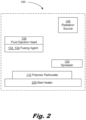
- a system including: a spreader to form layers of polymer particles, the polymer particles having a melting temperature (Tm) of at least 250° C; a fluid ejection head to selectively deposit a fusing agent on a top layer of the layers of polymer particles; a bed heater to heat a working area of the system to no more than 10 degrees centigrade below the Tm of the polymer particles; and a radiation source to selectively heat the top layer, wherein spreading a new layer on top of the layers of polymer particulate, applying the fusing agent to the new layer, and heating the new layer with the radiation source are accomplished such that the temperature of the top layer remains above a solidification temperature (Ts) of the polymer particles until the top layer is covered by the new layer.
- Tm melting temperature
- the system (100) is a system for forming a multiple layer object from a high melting temperature polymer.
- a layer of polymer particles (110) is formed and then selectively consolidated to form a layer of the object.
- Another layer of polymer particles (110) is applied and the process repeated.
- the object is built up layer by layer until the desired thickness is reached.
- This approach has some advantages over providing the material for the object through deposition.
- the use of consolidated polymer particles (110) may have higher throughput and/or quicker layer times.
- the use of consolidated polymer particles (110) may have thicker layers, reducing the total object forming time.
- the use of consolidated polymer particles (110) may make producing distributions of color, composition, strength, etc. within the formed object more difficult compared with a system where different materials are deposited to build up the component.
- the use of a consolidated polymer particle (110) approach also uses a spreader (120) to form the layer of polymer particles (110).
- the polymer particles (110) provide the material to form the multiple layer object.
- the polymer particles (110) include high melting temperature polymer.
- High melting temperature polymers may be polymers with a melting temperature above 250° C.
- High melting temperature polymers may be polymers with a melting temperature above 300° C.
- High melting temperature polymers may be polymers with a melting temperature above 325° C.
- high melting temperature polymers include, but are not limited to: Fluorinated ethylene propylene (FEP, Tm of 260 ° C); Perfluoroalkoxy alkane (PFA, Tm of 260 ° C); Polyamide 6,6 (Nylon 6,6) (PA 6,6, Tm of 265° C); Polyphenylene sulfide (PPS, Tm of 280° C); Polyamide 4,6 (PA 4,6, Tm of 280° C); Polyphthalamide (PPA, Tm of 310° C); Liquid crystal polymer-Glass composite (e.g.
- LCP Liquid crystal polymers
- the polymer particles (110) may be of a single polymer, for example, PEEK.
- the polymer particles (110) may be a mixture of polymers, e.g. PA 6,6 and PA 4,6.
- the polymer particles (110) may be in a single distribution.
- the polymer particles (110) may include multiple size distributions, for example, a larger mean size distribution and a smaller mean size distribution to create a bimodal distribution.
- the smaller particles are formed with a higher melting temperature (Tm) polymer.
- Tm melting temperature
- the smaller particles are formed from a lower melting temperature polymer.
- Tm melting temperature
- the use of a bimodal size distribution may achieve higher density parts than the use of a single size distribution.
- the polymer particles (110) may be mixed with other components to modify the formed multilayer object. Care and experimentation may be needed as adding additional components, e.g. a flow agent and/or a colorant, may impact the performance of the polymer particles (110).
- additional components e.g. a flow agent and/or a colorant
- the tackiness of the polymer particles (110) is sensitive to additional components. This is consistent with a working theory that the tackiness at higher temperatures is driven by the behavior of amorphous portions of a semi crystalline high melting temperature polymer. If the crystalline portions remain intact in the tacky particles, then a very thin surface component is able to effectively interact with other particles. However, the thinness of the interacting layer may allow this behavior to be disrupted by relatively small amounts of secondary materials.
- the spreader (120) is used to form a layer of polymer particles (110).
- the spreader (120) may include a feed to provide additional particulate to form the layer of polymer particles (110).
- the spreader (120) may include a vibrating component to distribute and/or compact the layer of polymer particles (110).
- the spreader (120) may make a single pass to form the layer of polymer particles (110).
- the spreader may make multiple passes to form the layer of polymer particles (110). In some examples, the subsequent passes increase the density of the layer of polymer particles (110).
- the spreader (120) may be automatic.
- the spreader (120) may be semi-automatic.
- the spreader (120) may be manually operated by a user.
- the spreader (120) may form layers of polymer particles (110) that are of a uniform depth.
- the spreader may vary the depth of the formed layer of polymer particles (110) as a function of location in the part, location in the bed, and/or feature resolution.
- the spreader (120) uses a first thickness for the initial layer and/or the initial few layers and then changes to a second thickness for subsequent layers.
- the spreader (120) may include multiple particle feeds.
- the spreader (120) provides a first distribution of particles for the initial layer and a second distribution of particles in subsequent layers.
- the spreader (120) may apply a first distribution of particles on a first pass and a second distribution of smaller particle on a second pass.
- the spreader (120) may apply a first distribution of smaller particles near the bottom of the layer and a second distribution including more, larger particles near the top of the layer of polymer particulate (110).
- the fluid ejection head (130) ejects the first fusing agent (132) and the second fusing agent (134) onto the layer of polymer particles (120).
- the fluid ejection head (130) may be part of a printbar.
- the fluid ejection head (130) may be static and/or move relative to a forming area.
- the fluid ejection head (130) may include a plurality of solutions for patterning on the polymer particles (110).
- the fluid ejection head (130) may contain a fusing agent (132, 134).
- the fluid ejection head may include a masking fluid to selectively reduce absorption of the radiation from the radiation source (140).
- the first fusing agent (132) increases the energy absorbed by the radiation source (140).
- the first fusing agent (132) may absorb a broad spectrum of electromagnetic radiation.
- the first fusing agent (132) may absorb a narrow wavelength of electromagnetic radiation.
- the first fusing agent (132) may be carried in a solvent, where the solvent acts as the propellant in the fluid ejection head.
- the first fusing agent (132) may be in water.
- the first fusing agent may be mixed with a humectant, an anti-kogation agent, a detergent, an ion source, a pH modifier, a chelator, and/or combinations thereof.
- the second fusing agent (134) increases the energy absorbed from the radiation source (140).
- the second fusing agent (134) may be the same agent as the first fusing agent (132) but at a different concentration in solution.
- the second fusing agent (134) may be the same formulation as the first fusing agent (132) but applied at a different density on the polymer particles (110).
- the first fusing agent (132) and the second fusing agent (134) may include different materials.
- Fusing agents (132, 134) may include: carbon black, platinum black, titanium black, ivory black, black iron oxide, graphite, aniline black, and/or anthraquinone black.
- the first fusing agent (132) and second fusing agent (134) may include any near infrared absorbing dyes and/or pigments. These may include materials which strongly absorb in the infrared and/or visible regime. Some other examples include doped cesium-tungsten oxide pigments and metal ditholene chemical dyes. Further discussion of fusing agents (132, 134) may be found in PCT/US2017/016681, "Fusing Agent including a Metal bis(Dithiolene) Complex" by Olubummo , which is incorporated by reference.
- the radiation source (140) provides energy that is preferentially absorbed by the portions of the layer of polymer particles (110) that have been treated with the first fusing agent (132) and/or the second fusing agent (134).
- the untreated areas of the layer of polymer particles (110) may absorb energy from the radiation source (140).
- the untreated polymer particles (110) may absorb less than 10% of the energy of the radiation from the radiation source falling on the untreated polymer particles (110). That is to say, in some examples, more than 90% of the radiation is reflected and/or transmitted by the untreated polymer particles (110).
- the radiation source (140) may be a pulsed irradiation light source.
- Pulsed irradiation light sources are capable of applying large amounts of light in a relatively short period of time. This makes pulsed irradiation light sources a useful energy source for high throughput operations such as three dimensional forming.
- Pulsed irradiation light sources may also be used in a flood mode, rather than as a point source, for example, like a laser. Irradiating the entire treatment area simultaneously provides throughput advantages as well as uniformity advantages. Simultaneous treatment of the layer of polymer particles (110) may reduce the internal stresses in the consolidated part. Simultaneous treatment may produce more uniform heating and cooling.
- Pulsed irradiation light sources may be monochromatic. Pulsed irradiation light sources may have a distribution of wavelengths, including wavelengths in the infrared, visible, and/or ultraviolet frequencies. Pulsed irradiation light sources may use a light emitting diode (LED), an array of LEDs, plasmas, filaments, and/or other components to generate the electromagnetic radiation used to heat the polymer particles (120).
- LED light emitting diode
- the radiation source (140) may provide the radiation as a single pulse.
- the radiation source (140) may provide the radiation as a series of pulses.
- the pulses may be of the same wavelength and/or energy.
- the pulses may vary, for example, a first type of pulse may be used to heat the polymer particles (120) and a second pulse with a different energy, wavelength, duration, frequency, spectrum, and/or other property may be used after the first pulse.
- the wavelength of the radiation provided by the radiation source may be selected based on a preferential absorbance frequency of the fusing agent, for example, based on a bond found in the fusing agent but not found in the polymer particles (110).
- a heating pulse and/or maintenance pulse may be applied that is not dependent on the preferential absorbance of the fusing agent. Selecting a wavelength that preferentially interacts with a characteristic chemical bond in the polymer particles (110) may be useful.
- FIG. 2 is a diagram of a system according to one example consistent with the present specification.
- the system (100) includes: a spreader (120) to form layers of polymer particles (110), the polymer particles having a melting temperature (Tm) of at least 250° C; a fluid ejection head (130) to selectively deposit a fusing agent (132, 134) on a top layer of the layers of polymer particles (110); a bed heater (250) to heat a working area of the system to no more than 10 degrees centigrade below the Tm of the polymer particles (110); and a radiation source (140) to selectively heat the top layer of polymer particles (110), wherein spreading a new layer on top of the layers of polymer particles (110), applying the fusing agent (132, 134) to the new layer, and heating the new layer with the radiation source (140) are accomplished such that the temperature of the top layer remains above a solidification temperature (Ts) of the polymer particles (110) until the top layer is covered by the new layer.
- the system (100) is a system for forming consolidated parts from polymer particles (110).
- the system (100) uses a fusing agent (132, 134) to selectively heat portions of a layer of polymer particles (110).
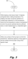
- FIG. 3 shows a flowchart for a method (300) of forming a multiple layer assembly using a polymer with a melting temperature (Tm).
- the method (300) includes: while keeping a bed area at least 10 degrees centigrade below Tm, heating a top layer of polymer particles (110) of a multiple layer assembly to a first temperature, where the first temperature is above a temperature at which the polymer particles (110) become sufficient tacky to resist displacement by a deposited agent (390); and while a top surface of the top layer is at the first temperature, selectively applying a fusing agent (132, 134) to the top surface of the top layer using a fluid ejection head (130)(392).
- the method (300) includes, while keeping a bed area at least 10 degrees centigrade below Tm, heating a top layer of polymer particles (110) of a multiple layer assembly to a first temperature, where the first temperature is above a temperature at which the polymer particles (110) become sufficient tacky to resist displacement by a deposited agent (390. Getting the layer of polymer particles (110) to become tacky so as to resist displacement allows patterning with the fusing agent without disrupting the layer. The presence of this tacky zone between the boiling point of the fusing agent (132, 134) solution and the melting temperature of the polymer particulate increases dimensional control of the formed object.
- the method (300) includes, while a top surface of the top layer is at the first temperature, selectively applying a fusing agent (132, 134) to the top surface of the top layer using a fluid ejection head (130)(392).
- a fusing agent 132, 134
- selective application of the fusing agent enables selective heating of the areas to form the consolidated part while other areas remain at a lower, bed temperature to avoid damage to the system (100).
- the use of the polymer particulate to insulate the forming area and the ability to rapidly form a layer, patterning the layer, and selective heat the desired portions allow forming a consolidated part from a polymer with a high melting temperature without hardening the system. This dynamic control approach offers equipment cost and throughput advantages over systems that bring the bed to near the melting temperature of the polymer particulate (110).
- the behavior may change.
- a droplet is dropped onto a surface that is higher temperature than the boiling point of the droplet, the contact with the surface may form a vapor layer that lifts and propels the droplet chaotically around the surface.
- a common example of this is a droplet of water on a hot pan.
- the motion of the droplet may disrupt the layer of polymer particles as the droplet darts back and forth across the surface and/or from pressure build-up from evaporating gases.
- the second temperature is 70 degrees C below Tm. In some examples, the second temperature is 50 degrees C below Tm. The second temperature may be 30 degrees C below Tm. The second temperature may be 20 degrees C below Tm. Determination of the second temperature will depend on the polymer particles (110) including their composition.
- the bed temperature may be limited to 120 ° C.
- the bed temperature may be limited to 150 ° C.
- the bed temperature may be limited to 180 ° C.
- Other bed temperatures may be selected depending on the temperature tolerances of the system (100) and components of the system (100) in the bed area. Temperature differences up to approximately 400° C between the bed temperature and the peak temperature of the polymer layer (110) may be supported with proper layer patterning and diligent control. The ability to rapidly form, pattern, and heat the top layer is part of achieving larger temperature differences and avoiding excessive cooling while forming the object.
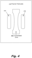
- FIG. 4 shows top view of a layer of polymer particulate (110) with both the consolidated zone (460) that will form the part and the heat reservoirs (470) according to one example of the principles described herein.
- FIG. 4 shows a consolidated zone (460) in the shape of a tensile test specimen (a.k.a. a "dogbone").
- Heat reservoirs (470) are located on either side of the narrower portion of the test specimen. The addition of the heat reservoirs (470) near the narrower portion of the consolidated zone (460) helps to equalize the cooling rate of the ends of the test specimen and the center of the test specimen. The extra heat provided by the heat reservoirs (470) also slows the cooling rate of the layer overall, for example, to keep the consolidated zone (460) and/or the heat reservoirs (470) above the solidification temperature (Ts) of the polymer making up the polymer particles.
- Ts solidification temperature
Claims (14)
- System (100) zum Bilden eines Mehrschichtobjekts, wobei das System umfasst: einen Streuer zum Bilden einer Schicht von Polymerteilchen (110), wobei die Polymerteilchen eine Schmelztemperatur (Tm) von mindestens 250 °C aufweisen;einen Fluidausstoßkopf (130), der konfiguriert ist, selektiv ein erstes Schmelzmittel auf einen ersten Abschnitt der Schicht abzuscheiden und selektiv ein zweites Schmelzmittel auf einen zweiten Abschnitt der Schicht abzuscheiden und kein Schmelzmittel auf einen dritten Abschnitt der Schicht abzuscheiden; undeine Wärmequelle (140) zum Erwärmen des ersten Abschnitts und des zweiten Abschnitts, wobei der erste Abschnitt Teil des Mehrschichtobjekts ist und der zweite Abschnitt nicht Teil des Mehrschichtobjekts ist undwobei der zweite Abschnitt einen thermischen Gradienten zwischen dem ersten Abschnitt und anderen Abschnitten der Schicht, die nicht Teil des gebildeten Objekts sein werden, reduziert und eine Temperatur von Polymerpartikeln in einer nachfolgenden Schicht erhöht.
- System (100) nach Anspruch 1, wobei das erste Schmelzmittel mit einer ersten Dichte auf den ersten Abschnitt der Schicht aufgebracht wird und das zweite Schmelzmittel mit einer zweiten Dichte auf den zweiten Abschnitt der Schicht aufgebracht wird.
- System (100) nach Anspruch 1, wobei der erste Abschnitt der Schicht eine erste Dichte des ersten Schmelzmittels an einem Rand des Abschnitts und eine zweite Dichte des ersten Schmelzmittels in einer Mitte des Abschnitts aufweist.
- System (100) nach Anspruch 1, wobei das erste Schmelzmittel und das zweite Schmelzmittel ein gemeinsames Funktionsmaterial umfassen.
- System (100) nach Anspruch 1, wobei die Wärmequelle den ersten Abschnitt, den zweiten Abschnitt und den dritten Abschnitt gleichzeitig mit Wärme versorgt.
- System (100) nach Anspruch 1, wobei die Wärmequelle den ersten Abschnitt, den zweiten Abschnitt und den dritten Abschnitt der Schicht gleichmäßig bestrahlt.
- System (100) nach Anspruch 1, wobei der erste Abschnitt aufgrund von Wärmezufuhr durch die Wärmequelle schmilzt und der zweite Abschnitt aufgrund von Wärmezufuhr durch die Wärmequelle nicht schmilzt.
- System (100) nach Anspruch 1, das umfasst:
eine Bettheizung (250) zum Erwärmen eines Bildungsbereichs des Systems auf eine Temperatur, die um mehr als 10 Grad Celsius unter der Schmelztemperatur der Polymerteilchen liegt. - System (100) nach Anspruch 8, wobei der zweite Abschnitt über der Erstarrungstemperatur gehalten wird, bis die obere Schicht, die einen Erstarrungsabschnitt enthält, mit einer neuen Schicht von Polymerteilchen bedeckt ist.
- System (100) nach Anspruch 8, wobei ein Polymer, das die Polymerteilchen bildet, ein halbkristallines Polymer ist.
- System (100) nach Anspruch 10, wobei eine obere Oberfläche der oberen Schicht von Polymerteilchen vor dem selektiven Aufbringen des Schmelzmittels eine Temperatur von einer Erstarrungstemperatur (Ts) auf eine Schmelztemperatur (Tm) aufweist.
- Verfahren (300) zum Bilden eines Mehrschichtobjekts unter Verwendung eines Polymers mit einer Schmelztemperatur (Tm), wobei das Verfahren umfasst:Erwärmen (390) einer oberen Schicht von Polymerteilchen eines Mehrschichtobjekts auf eine erste Temperatur, wobei die erste Temperatur über einer Temperatur liegt, bei der die Polymerteilchen ausreichend klebrig werden, um einer Verdrängung durch ein abgeschiedenes Mittel zu widerstehen, während ein Bettbereich mindestens 10 Grad Celsius unter der Schmelztemperatur (Tm) gehalten wird; undwährend sich eine obere Oberfläche der oberen Schicht auf der ersten Temperatur befindet, selektives Aufbringen eines ersten Schmelzmittels auf die obere Oberfläche auf einem ersten Abschnitt der oberen Schicht und selektives Aufbringen eines zweiten Schmelzmittels auf einen zweiten Abschnitt der oberen Schicht unter Verwendung eines Fluidausstoßkopfes und kein Abscheiden eines Schmelzmittels auf einem dritten Abschnitt der Schicht,wobei der erste Abschnitt Teil des Mehrschichtobjekts ist und der zweite Abschnitt nicht Teil des Mehrschichtobjekts ist; undwobei der zweite Abschnitt einen thermischen Gradienten zwischen dem ersten Abschnitt und anderen Abschnitten der Schicht, die nicht Teil des gebildeten Objekts sein werden, reduziert und eine Temperatur von Polymerteilchen in einer nachfolgenden Schicht erhöht.
- Verfahren (300) nach Anspruch 12, das ferner das Erwärmen eines Abschnitts der oberen Schicht unter Verwendung von Strahlung, die durch das selektiv aufgebrachte Schmelzmittel absorbiert wird, umfasst.
- Verfahren (300) nach Anspruch 13, das ferner umfasst: Bilden einer neuen oberen Schicht über der oberen Schicht; und
Wiederholen des Erwärmens, selektiven Auftragens und Bildens, um ein erstarrt
es Mehrschichtobjekt aufzubauen, während die Betttemperatur mindestens 10 Grad Celsius unter der Schmelztemperatur (Tm) bleibt.
Applications Claiming Priority (1)
| Application Number | Priority Date | Filing Date | Title |
|---|---|---|---|
| PCT/US2017/028951 WO2018194679A1 (en) | 2017-04-21 | 2017-04-21 | 3d forming objects using high melting temperature polymers |
Publications (3)
| Publication Number | Publication Date |
|---|---|
| EP3551425A1 EP3551425A1 (de) | 2019-10-16 |
| EP3551425A4 EP3551425A4 (de) | 2020-08-12 |
| EP3551425B1 true EP3551425B1 (de) | 2023-12-20 |
Family
ID=63856048
Family Applications (1)
| Application Number | Title | Priority Date | Filing Date |
|---|---|---|---|
| EP17906582.6A Active EP3551425B1 (de) | 2017-04-21 | 2017-04-21 | Dreidimensionales formen von gegenständen mit polymeren mit hoher schmelztemperatur |
Country Status (7)
| Country | Link |
|---|---|
| US (2) | US11413815B2 (de) |
| EP (1) | EP3551425B1 (de) |
| JP (1) | JP6832438B2 (de) |
| KR (1) | KR102212911B1 (de) |
| CN (1) | CN110430987B (de) |
| BR (1) | BR112019017354B1 (de) |
| WO (1) | WO2018194679A1 (de) |
Families Citing this family (1)
| Publication number | Priority date | Publication date | Assignee | Title |
|---|---|---|---|---|
| WO2020204911A1 (en) * | 2019-04-02 | 2020-10-08 | Hewlett-Packard Development Company, L.P. | Melt temperature determination for 3d object generation |
Family Cites Families (22)
| Publication number | Priority date | Publication date | Assignee | Title |
|---|---|---|---|---|
| ATE223300T1 (de) | 1995-09-27 | 2002-09-15 | 3D Systems Inc | Formungsverfahren durch selektiven materialabsatz und vorrichtung zur formung von dreidimensionalen gegenständen mit stützstruktur |
| JPH09207228A (ja) | 1996-02-06 | 1997-08-12 | Toshiba Corp | 光造形装置 |
| US6019814A (en) | 1997-11-25 | 2000-02-01 | Xerox Corporation | Method of manufacturing 3D parts using a sacrificial material |
| US20070241482A1 (en) * | 2006-04-06 | 2007-10-18 | Z Corporation | Production of three-dimensional objects by use of electromagnetic radiation |
| US20100028645A1 (en) | 2008-08-04 | 2010-02-04 | Michael Maguire | Adaptive supports for green state articles and methods of processing thereof |
| JP2016513200A (ja) | 2013-01-31 | 2016-05-12 | シーメンス エナジー インコーポレイテッド | 超合金部品の局所修理 |
| WO2015106840A1 (en) | 2014-01-16 | 2015-07-23 | Hewlett-Packard Development Company L.P. | Processing slice data for an additive manufacturing system |
| WO2015106836A1 (en) * | 2014-01-16 | 2015-07-23 | Hewlett-Packard Development Company, L.P. | Processing three-dimensional object data of an object to be generated by an additive manufacturing process |
| JP2015139977A (ja) * | 2014-01-30 | 2015-08-03 | セイコーエプソン株式会社 | 三次元造形物の製造方法および三次元造形物 |
| WO2015167530A2 (en) * | 2014-04-30 | 2015-11-05 | Hewlett-Packard Development Company, L.P. | Three-dimensional (3d) printing method |
| KR102221213B1 (ko) * | 2014-09-29 | 2021-02-26 | 휴렛-팩커드 디벨롭먼트 컴퍼니, 엘.피. | 3차원(3d) 인쇄용 유착제 |
| EP3200977B1 (de) * | 2014-09-29 | 2021-06-02 | Hewlett-Packard Development Company, L.P. | Verfahren zum dreidimensionalen (3d) drucken |
| US11254068B2 (en) | 2014-10-29 | 2022-02-22 | Hewlett-Packard Development Company, L.P. | Three-dimensional (3D) printing method |
| US10800153B2 (en) * | 2014-11-20 | 2020-10-13 | Hewlett-Packard Development Company, L.P. | Generating three-dimensional objects |
| US20160167089A1 (en) | 2014-12-11 | 2016-06-16 | Palo Alto Research Center Incorporation | Forming sacrificial structures using phase-change materials that sublimate |
| WO2016115046A1 (en) | 2015-01-12 | 2016-07-21 | Polyone Corporation | Support material for 3d printing of polymer compounds |
| KR101980466B1 (ko) | 2015-03-05 | 2019-05-20 | 휴렛-팩커드 디벨롭먼트 컴퍼니, 엘.피. | 삼차원 물체 생성 기법 |
| US9694423B2 (en) | 2015-04-09 | 2017-07-04 | Siemens Energy, Inc. | Laser additive manufacturing using filler material suspended in a liquid carrier |
| BR112017015821A2 (pt) | 2015-04-30 | 2018-07-17 | Hewlett-Packard Development Company, L.P. | impressão de um objeto 3d multiestruturado |
| US10807305B2 (en) | 2015-06-02 | 2020-10-20 | Hewlett-Packard Development Company, L.P. | Sacrificial objects based on a temperature threshold |
| CN107548347A (zh) * | 2015-07-23 | 2018-01-05 | 惠普发展公司有限责任合伙企业 | 三维(3d)打印方法 |
| CN107530968A (zh) * | 2015-07-30 | 2018-01-02 | 惠普发展公司有限责任合伙企业 | 用于3d打印的受控加热 |
-
2017
- 2017-04-21 US US16/076,338 patent/US11413815B2/en active Active
- 2017-04-21 KR KR1020197024027A patent/KR102212911B1/ko active IP Right Grant
- 2017-04-21 BR BR112019017354-4A patent/BR112019017354B1/pt active IP Right Grant
- 2017-04-21 CN CN201780086685.8A patent/CN110430987B/zh active Active
- 2017-04-21 WO PCT/US2017/028951 patent/WO2018194679A1/en unknown
- 2017-04-21 EP EP17906582.6A patent/EP3551425B1/de active Active
- 2017-04-21 JP JP2019539841A patent/JP6832438B2/ja active Active
-
2022
- 2022-05-25 US US17/824,197 patent/US11904537B2/en active Active
Also Published As
| Publication number | Publication date |
|---|---|
| BR112019017354B1 (pt) | 2022-11-08 |
| EP3551425A4 (de) | 2020-08-12 |
| WO2018194679A1 (en) | 2018-10-25 |
| CN110430987A (zh) | 2019-11-08 |
| BR112019017354A2 (pt) | 2020-03-31 |
| JP6832438B2 (ja) | 2021-02-24 |
| US11413815B2 (en) | 2022-08-16 |
| US11904537B2 (en) | 2024-02-20 |
| KR20190103404A (ko) | 2019-09-04 |
| US20210197454A1 (en) | 2021-07-01 |
| EP3551425A1 (de) | 2019-10-16 |
| JP2020504040A (ja) | 2020-02-06 |
| US20220281165A1 (en) | 2022-09-08 |
| CN110430987B (zh) | 2021-11-16 |
| KR102212911B1 (ko) | 2021-02-05 |
Similar Documents
| Publication | Publication Date | Title |
|---|---|---|
| CN111356738B (zh) | 用于三维打印的抗聚结剂 | |
| JP6669985B2 (ja) | 三次元造形物の製造方法 | |
| EP3377290B1 (de) | Steuerung der oberflächeneigenschaften von bedruckten dreidimensionalen strukturen | |
| KR102130284B1 (ko) | 3d 프린팅을 위한 가열을 제어하는 기법 | |
| RU2692342C2 (ru) | Формирование трехмерных объектов | |
| US20140252685A1 (en) | Powder Bed Fusion Systems, Apparatus, and Processes for Multi-Material Part Production | |
| KR20170097055A (ko) | 적층에 의한 3d 형상 물품의 제조 방법 및 장치 | |
| US11904537B2 (en) | 3D forming objects using high melting temperature polymers | |
| US11504904B2 (en) | Additive manufacturing by selective liquid cooling | |
| CN110366465B (zh) | 三维造型物制造用组合物、三维造型物的制造方法以及三维造型物制造装置 | |
| US10773460B2 (en) | Method and apparatus for manufacturing three-dimensional body | |
| US11007712B2 (en) | Three-dimensional (3D) printing with epoxy resin | |
| CN115666822A (zh) | 逐层溶剂蒸发 | |
| EP3551366B1 (de) | Reduzierung von spannungen bei metallschichten | |
| US11766826B2 (en) | Reducing stresses in metal layers | |
| JP6730412B2 (ja) | 3次元物体の生成 | |
| EP3673414B1 (de) | Generative fertigung durch selektive flüssigkeitskühlung | |
| US20230405923A1 (en) | Printing with multiple carriages | |
| CN117098648A (zh) | 用于三维打印的阿伏苯宗熔合剂 |
Legal Events
| Date | Code | Title | Description |
|---|---|---|---|
| STAA | Information on the status of an ep patent application or granted ep patent |
Free format text: STATUS: THE INTERNATIONAL PUBLICATION HAS BEEN MADE |
|
| PUAI | Public reference made under article 153(3) epc to a published international application that has entered the european phase |
Free format text: ORIGINAL CODE: 0009012 |
|
| STAA | Information on the status of an ep patent application or granted ep patent |
Free format text: STATUS: REQUEST FOR EXAMINATION WAS MADE |
|
| 17P | Request for examination filed |
Effective date: 20190708 |
|
| AK | Designated contracting states |
Kind code of ref document: A1 Designated state(s): AL AT BE BG CH CY CZ DE DK EE ES FI FR GB GR HR HU IE IS IT LI LT LU LV MC MK MT NL NO PL PT RO RS SE SI SK SM TR |
|
| AX | Request for extension of the european patent |
Extension state: BA ME |
|
| REG | Reference to a national code |
Ref country code: DE Ref legal event code: R079 Ref document number: 602017077805 Country of ref document: DE Free format text: PREVIOUS MAIN CLASS: B29C0064100000 Ipc: B29C0064165000 Ref country code: DE Ref legal event code: R079 Free format text: PREVIOUS MAIN CLASS: B29C0064100000 Ipc: B29C0064165000 |
|
| DAV | Request for validation of the european patent (deleted) | ||
| DAX | Request for extension of the european patent (deleted) | ||
| A4 | Supplementary search report drawn up and despatched |
Effective date: 20200710 |
|
| RIC1 | Information provided on ipc code assigned before grant |
Ipc: B33Y 30/00 20150101ALI20200706BHEP Ipc: B33Y 10/00 20150101ALI20200706BHEP Ipc: B33Y 70/00 20200101ALI20200706BHEP Ipc: B29C 64/165 20170101AFI20200706BHEP Ipc: B29C 64/295 20170101ALI20200706BHEP |
|
| STAA | Information on the status of an ep patent application or granted ep patent |
Free format text: STATUS: EXAMINATION IS IN PROGRESS |
|
| 17Q | First examination report despatched |
Effective date: 20220506 |
|
| GRAP | Despatch of communication of intention to grant a patent |
Free format text: ORIGINAL CODE: EPIDOSNIGR1 |
|
| STAA | Information on the status of an ep patent application or granted ep patent |
Free format text: STATUS: GRANT OF PATENT IS INTENDED |
|
| INTG | Intention to grant announced |
Effective date: 20221116 |
|
| GRAJ | Information related to disapproval of communication of intention to grant by the applicant or resumption of examination proceedings by the epo deleted |
Free format text: ORIGINAL CODE: EPIDOSDIGR1 |
|
| STAA | Information on the status of an ep patent application or granted ep patent |
Free format text: STATUS: EXAMINATION IS IN PROGRESS |
|
| INTC | Intention to grant announced (deleted) | ||
| GRAP | Despatch of communication of intention to grant a patent |
Free format text: ORIGINAL CODE: EPIDOSNIGR1 |
|
| STAA | Information on the status of an ep patent application or granted ep patent |
Free format text: STATUS: GRANT OF PATENT IS INTENDED |
|
| INTG | Intention to grant announced |
Effective date: 20230908 |
|
| GRAS | Grant fee paid |
Free format text: ORIGINAL CODE: EPIDOSNIGR3 |
|
| GRAA | (expected) grant |
Free format text: ORIGINAL CODE: 0009210 |
|
| STAA | Information on the status of an ep patent application or granted ep patent |
Free format text: STATUS: THE PATENT HAS BEEN GRANTED |
|
| AK | Designated contracting states |
Kind code of ref document: B1 Designated state(s): AL AT BE BG CH CY CZ DE DK EE ES FI FR GB GR HR HU IE IS IT LI LT LU LV MC MK MT NL NO PL PT RO RS SE SI SK SM TR |
|
| REG | Reference to a national code |
Ref country code: GB Ref legal event code: FG4D |
|
| REG | Reference to a national code |
Ref country code: CH Ref legal event code: EP |
|
| REG | Reference to a national code |
Ref country code: DE Ref legal event code: R096 Ref document number: 602017077805 Country of ref document: DE |
|
| REG | Reference to a national code |
Ref country code: IE Ref legal event code: FG4D |
|
| PG25 | Lapsed in a contracting state [announced via postgrant information from national office to epo] |
Ref country code: GR Free format text: LAPSE BECAUSE OF FAILURE TO SUBMIT A TRANSLATION OF THE DESCRIPTION OR TO PAY THE FEE WITHIN THE PRESCRIBED TIME-LIMIT Effective date: 20240321 |
|
| REG | Reference to a national code |
Ref country code: LT Ref legal event code: MG9D |
|
| PG25 | Lapsed in a contracting state [announced via postgrant information from national office to epo] |
Ref country code: LT Free format text: LAPSE BECAUSE OF FAILURE TO SUBMIT A TRANSLATION OF THE DESCRIPTION OR TO PAY THE FEE WITHIN THE PRESCRIBED TIME-LIMIT Effective date: 20231220 |