EP3551296B1 - Harnais à absorbeur d'énergie intégré - Google Patents
Harnais à absorbeur d'énergie intégré Download PDFInfo
- Publication number
- EP3551296B1 EP3551296B1 EP17829772.7A EP17829772A EP3551296B1 EP 3551296 B1 EP3551296 B1 EP 3551296B1 EP 17829772 A EP17829772 A EP 17829772A EP 3551296 B1 EP3551296 B1 EP 3551296B1
- Authority
- EP
- European Patent Office
- Prior art keywords
- shoulder strap
- harness
- webbing
- strap
- energy absorbing
- Prior art date
- Legal status (The legal status is an assumption and is not a legal conclusion. Google has not performed a legal analysis and makes no representation as to the accuracy of the status listed.)
- Active
Links
- 239000006096 absorbing agent Substances 0.000 title description 3
- 239000011230 binding agent Substances 0.000 claims description 44
- 239000000463 material Substances 0.000 claims description 37
- 239000000853 adhesive Substances 0.000 claims description 6
- 230000001070 adhesive effect Effects 0.000 claims description 6
- 238000000926 separation method Methods 0.000 claims description 6
- 230000000670 limiting effect Effects 0.000 description 36
- 230000007246 mechanism Effects 0.000 description 16
- 238000010276 construction Methods 0.000 description 8
- 230000003247 decreasing effect Effects 0.000 description 5
- 230000013011 mating Effects 0.000 description 4
- 238000010521 absorption reaction Methods 0.000 description 3
- 239000004677 Nylon Substances 0.000 description 2
- 208000027418 Wounds and injury Diseases 0.000 description 2
- 230000009286 beneficial effect Effects 0.000 description 2
- 238000000034 method Methods 0.000 description 2
- 229920001778 nylon Polymers 0.000 description 2
- 229920000728 polyester Polymers 0.000 description 2
- 230000002829 reductive effect Effects 0.000 description 2
- 239000011358 absorbing material Substances 0.000 description 1
- 230000004913 activation Effects 0.000 description 1
- 230000009194 climbing Effects 0.000 description 1
- 230000006378 damage Effects 0.000 description 1
- 230000007812 deficiency Effects 0.000 description 1
- 239000003292 glue Substances 0.000 description 1
- 210000004013 groin Anatomy 0.000 description 1
- 208000014674 injury Diseases 0.000 description 1
- 238000004519 manufacturing process Methods 0.000 description 1
- 238000012986 modification Methods 0.000 description 1
- 230000004048 modification Effects 0.000 description 1
- 230000008569 process Effects 0.000 description 1
- 230000002441 reversible effect Effects 0.000 description 1
- 230000035939 shock Effects 0.000 description 1
- 230000003068 static effect Effects 0.000 description 1
- 239000000725 suspension Substances 0.000 description 1
Images


Classifications
-
- A—HUMAN NECESSITIES
- A62—LIFE-SAVING; FIRE-FIGHTING
- A62B—DEVICES, APPARATUS OR METHODS FOR LIFE-SAVING
- A62B35/00—Safety belts or body harnesses; Similar equipment for limiting displacement of the human body, especially in case of sudden changes of motion
- A62B35/0006—Harnesses; Accessories therefor
- A62B35/0025—Details and accessories
-
- A—HUMAN NECESSITIES
- A62—LIFE-SAVING; FIRE-FIGHTING
- A62B—DEVICES, APPARATUS OR METHODS FOR LIFE-SAVING
- A62B35/00—Safety belts or body harnesses; Similar equipment for limiting displacement of the human body, especially in case of sudden changes of motion
- A62B35/04—Safety belts or body harnesses; Similar equipment for limiting displacement of the human body, especially in case of sudden changes of motion incorporating energy absorbing means
-
- A—HUMAN NECESSITIES
- A62—LIFE-SAVING; FIRE-FIGHTING
- A62B—DEVICES, APPARATUS OR METHODS FOR LIFE-SAVING
- A62B35/00—Safety belts or body harnesses; Similar equipment for limiting displacement of the human body, especially in case of sudden changes of motion
- A62B35/0006—Harnesses; Accessories therefor
- A62B35/0018—Full body harnesses covering at least shoulders and thighs
-
- A—HUMAN NECESSITIES
- A62—LIFE-SAVING; FIRE-FIGHTING
- A62B—DEVICES, APPARATUS OR METHODS FOR LIFE-SAVING
- A62B35/00—Safety belts or body harnesses; Similar equipment for limiting displacement of the human body, especially in case of sudden changes of motion
- A62B35/0006—Harnesses; Accessories therefor
- A62B35/0025—Details and accessories
- A62B35/0037—Attachments for lifelines and lanyards
Definitions
- full body harness While there are many variations in full body harness construction, all typically include a plurality of elongate straps that are combined together to fit around a user's body.
- a full body harness may have an attachment point (D-ring) typically positioned in a central portion of the user's back, and a plurality of straps routed around predetermined portions of the user's body in such a manner as to hold or suspend the user in the event of a fall.
- D-ring attachment point
- the drum can rotate in a first direction to unwind (or "pay out") the line from the housing when a certain level of tension is deliberately applied.
- the braking mechanism is configured for slowing down and stopping the rotation of the drum when the line unwinds too rapidly.
- the braking mechanism may be activated to brake the rotation of the drum when the rotation speed exceeds a predetermined velocity.
- a sudden line pay out at a speed that exceeds normal payout is an indication that the user has experienced a fall that needs to be stopped or arrested. Should such an unintentional, accidental fall commence, the braking mechanism in the housing of the SRL is configured to engage and stop the user from falling too far.
- a wearable harness having a plurality of straps, optionally including a first leg strap and a second leg strap, each leg strap having a first end and a second end removably attached to each other and configured to be free floating when detached from each other.
- the harness may optionally further include a belt strap having a first end and a second end removably attached to each other and configured to be free floating when detached from each other.
- the harness includes a shoulder strap having a first shoulder strap, and a second shoulder strap. One or both of the first shoulder strap and the second shoulder strap may have an energy absorbing element integrated therewith.
- the energy absorbing element may have a tubular webbing encasing a tearable webbing material with at least two bound (e.g., load-bearing) webbing components configured to tear from one another when the shoulder strap is subjected to a force that exceeds a predetermined threshold. Accordingly, the energy absorbing element may be integrated on or with at least a portion of at least one of the shoulder straps.
- bound (e.g., load-bearing) webbing components configured to tear from one another when the shoulder strap is subjected to a force that exceeds a predetermined threshold. Accordingly, the energy absorbing element may be integrated on or with at least a portion of at least one of the shoulder straps.
- the energy absorbing element may be exposed from the tubular webbing at a substantially intermediate portion of at least one of the first shoulder strap and the second shoulder strap between the first end and the second end of the at least one of the first shoulder strap and the second shoulder strap.
- the energy absorbing element may be exposed from the tubular webbing through an opening in the tubular webbing.
- the opening may be a slit formed at a substantially intermediate portion of at least one of the first shoulder strap and the second shoulder strap between the first end and the second end of the at least one of the first shoulder strap and the second shoulder strap.
- At least a portion of the energy absorbing element may be configured to exit through the opening of the tubular webbing upon tearing.
- the tubular webbing may be made from a woven tubular material.
- the tubular webbing may be made from a substantially flat webbing material having opposing lateral ends connected to one another to define a tubular shape.
- the at least two bound webbing components may be bound by a plurality of binder threads or an adhesive.
- the plurality of binder threads may be configured to tear successively in a longitudinal direction of at least one of the first shoulder strap and the second shoulder strap when the at least one of the first shoulder strap and the second shoulder strap is subject to the force that exceeds the predetermined threshold.
- the plurality of binder threads may extend through at least a portion of a thickness of the at least two webbing components.
- the plurality of binder threads may be arranged in a row, or two or more rows extending along a longitudinal length or a lateral length of the webbing components.
- the rows may be substantially parallel to each other or intersect with each other at least once over the longitudinal length or the lateral length of the webbing components.
- the plurality of binder threads may be arranged in two or more thread groups spaced apart from each other along a longitudinal length or a lateral length of the webbing components.
- the two or more thread groups may be arranged in a pattern.
- a density of the plurality of binder threads may increase from the rear portion to the front portion of the shoulder strap, or vice versa.
- the predetermined threshold may be in the range of about 310 lbs to about 2,250 lbs.
- the first shoulder strap and the second shoulder strap may have a starting tear area at the rear portion where the pair of bound webbing components is unbound.
- the first shoulder strap and the second shoulder strap may have an ending tear point having a reinforced area configured to prevent separation of the at least two bound webbing components.
- the energy absorbing element may be located on an energy absorbing area at the rear portion of at least one of the first shoulder strap and the second shoulder strap.
- the first shoulder strap and the second shoulder strap may have a starting tear area at the rear portion where the pair of bound webbing components is unbound.
- the energy absorbing element may be located on an area at the rear portion of at least one of the first shoulder strap and the second shoulder strap.
- At least one connector may be arranged on at least one of the plurality of straps and configured to facilitate removable attachment of free floating ends of at least one of the plurality of straps.
- the connector may be at least one of the following: a clip, a buckle, a mating arrangement, an actuatable structure, or any combination thereof.
- the first end of each leg strap may be adjustably attached to the second end by a connection mechanism to adjust a length of each leg strap.
- the harness may have a chest strap having a first end and a second end removably attached to each other and configured to be free floating when detached from each other.
- the first end of the chest strap may be attached to the first shoulder strap and the second end of the chest strap may be attached to the second shoulder strap.
- the term "integrated”, when used with reference to an energy absorbing element and any portion of a harness, means that an energy absorbing element is formed as a separate component or arrangement and can be combined in, on, or with at least a portion of a separately formed harness (e.g., at least one strap or portion of a strap of the harness), such that the two components together constitute a whole. Therefore, the terms “therewith”, “therein”, and “thereon” are used interchangeably in the context of the present description.
- substantially parallel means a relative angle as between two objects (if extended to theoretical intersection), such as elongated objects and including reference lines, that is from 0° to 5°, or from 0° to 3°, or from 0° to 2°, or from 0° to 1°, or from 0° to 0.5°, or from 0° to 0.25°, or from 0° to 0.1°, inclusive of the recited values.
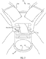
- the present disclosure is directed to a harness 100 used in a fall protection system.
- the harness 100 has at least one structural energy absorbing element integrated therewith and made from a tearable webbing material configured for absorbing energy during a fall event.
- the harness 100 may be used in combination with a supplementary energy absorbing element, such as a self-retracting lanyard (SRL) (not shown), to provide additional energy absorption during a fall event.
- SRL self-retracting lanyard
- the harness 100 has at least two leg straps 102 configured to attach around a user's legs below a user's groin area. When attached, the leg straps 102 loop around or encircle each of the user's legs.
- Each leg strap 102 has a first end 102a that is removably attachable to a second end 102b via a connector 104.
- the connector 104 may be a clip, a buckle, a mating arrangement, an actuatable structure, or the like. The connector 104 permits removable attachment of the first end 102a to the second end 102b of each leg strap 102.
- first and second ends 102a, 102b of the leg straps 102 are configured to be removably attached to each other and configured to be free floating when detached from each other.
- at least one connector 104 and/or the leg strap 102 may have at least one connection mechanism 106 configured for adjusting the length of each leg strap 102.
- the at least one connection mechanism 106 adjusts a distance between the first end 102a and the second end 102b such that each leg strap 102 may be adjusted to fit comfortably around the user's legs.
- Each leg strap 102 may be formed from a substantially flat webbing material typically used in harness construction.
- the leg straps 102 may be linear lengths of material, folded straps that form loops with the at least one connector 104 at the first end 102a and/or the second end 102b, or the like.
- the connector 104 may have a first portion 104a that is non-adjustably attached to the first end 102a of at least one leg strap 102, while a second portion 104b of the connector 104 is adjustably secured at the second end 102b of at least one leg strap 102 through a loop of the material that makes up the leg strap 102.
- the second portion 104b of the connector 104 and the loop of material that makes up the leg strap 102 at the second end 102b defines the at least one connection mechanism 106 for adjusting a length of the leg strap 102.
- the position of the connection mechanism 106 may be reversed such that the second portion 104b of the connector 104 is provided on the first end 102a of the leg strap 102.
- At least one leg strap 102 may have padding (not shown) for increasing the user's comfort while wearing the harness 100.
- each leg strap 102 is connected to a belt strap 110 at a substantially intermediate portion 102c of the leg strap 102 between the first end 102a and the second end 102b.
- each leg strap 102 may be connected to the belt strap 110.
- the substantially intermediate portion 102c of the leg strap 102 may be directly and non-movably connected to the belt strap 110, such as being sewn directly to the belt strap 110.
- the substantially intermediate portion 102c of each leg strap 102 may be connected to the rear end of the belt strap 110 by a connection strap (not shown) to allow the substantially intermediate portion 102c of the leg strap 102 to slidably move along a front portion of the leg strap 102. Accordingly, the position of the leg straps 102 may be adjusted relative to the belt strap 110 to increase the user's comfort while wearing the harness 100.
- the belt strap 110 is configured to encircle at least a portion of the user's torso.
- the belt strap 110 has a first end 110a that is attached to a first portion of a shoulder strap 126 and a second end 110b that is attached to a second portion of the shoulder strap 126.
- the first end 110a and the second end 110b may be removably or non-removably attachable to the shoulder strap 126.
- at least one of the first end 110a and the second end 110b may be attachable to the shoulder strap 126 via a connector similar to the connector 104 described herein with reference to the leg straps 102.
- the belt strap 110 may have at least one connection mechanism 106 configured for adjusting the length of the belt strap 110. In this manner, the at least one connection mechanism 106 adjusts a distance between the first end 110a and the second end 110b such that the belt strap 110 may be adjusted to fit comfortably around the user's torso.
- One or more handle connection members, and other handling and/or connectors 120 may be provided on at least a portion of the belt strap 110.
- the belt strap 110 may have padding (not shown) for increasing the user's comfort while wearing the harness 100.
- the belt strap 110 may be formed from a substantially flat webbing material typically used in harness construction.
- the harness 100 further has the shoulder strap 126 configured to extend over at least a portion of the user's shoulders.
- the shoulder strap 126 may have a first shoulder strap 126a and a second shoulder strap 126b arranged to overlap one another in an X-shaped configuration.
- the shoulder strap 126 may have at least one shoulder pad 131 having one or more openings through which the first shoulder strap 126a and the second shoulder strap 126b can be arranged to maintain the first shoulder strap 126a and the second shoulder strap 126b in the X-shaped configuration.
- the second end 127b of the first shoulder strap 126a is connected to the leg strap 102 proximate to the second end 102b of the leg strap 102, such as by being sewn directly to the leg strap 102.
- the first shoulder strap 126a may have at least one loop 128 through which the first end 110a of the belt strap 110 may be passed. At least a portion of the first shoulder strap 126a may be formed from a substantially flat webbing material typically used in harness construction.
- the second shoulder strap 126b has a first end 129a that is connected to the first end 110a of the belt strap 110.
- the first end 129a of the second shoulder strap 126b may be removably or non-removably attachable to first end 110a of the belt strap 110.
- the first end 129a of the second shoulder strap 126b may be attached to the first end 110a of the belt strap 110 via a connector similar to the connector 104 described herein with reference to the leg straps 102.
- the second shoulder strap 126b further has a second end 129b that is connected to the other of the two leg straps 102.
- the second end 129b of the second shoulder strap 126b is connected to the leg strap 102 proximate to the second end 102b of the leg strap 102, such as by being sewn directly to the leg strap 102.
- the second shoulder strap 126b may have at least one loop 128 through which the second end 110b of the belt strap 110 may be passed.
- At least a portion of the second shoulder strap 126b may be formed from a substantially flat webbing material typically used in harness construction.
- the harness 100 may have a back strap 130 connecting a substantially intermediate portion of the first shoulder strap 126a between its first end 127a and second end 127b with a substantially intermediate portion of the second shoulder strap 126b between its first end 129a and second end 129b.
- a position of the back strap 130 may be adjustable along a longitudinal direction of each the first shoulder strap 126a and the second shoulder strap 126b, such as by sliding the back strap 130 along the first shoulder strap 126a and/or the second shoulder strap 126b.
- the harness 100 further may have a chest strap 132 having a first end 132a removably connectable to a second end 132b.
- the first end 132a of the chest strap 132 may be positioned proximate to the first end 127a of the first shoulder strap 126a, while the second end 132b of the chest strap 132 may be positioned proximate to the first end 129a of the second shoulder strap 126b.
- the first end 132a of the chest strap 132 is removably attachable to the second end 132b via a connector, similar to the connector 104 described herein with reference to the leg straps 102.
- the connector 104 may be a clip, a buckle, a mating arrangement, an actuatable structure, or the like.
- the first and second ends 132a, 132b of the chest strap 132 are configured to be removably attached to each other and configured to be free floating when detached from each other.
- at least one of the back strap 130 and the chest strap 132 may have at least one connection mechanism, such as the connection mechanism 106 described herein with reference to the leg straps 102.
- the connection mechanism 106 is configured for adjusting the length of the back strap 130 and/or the chest strap 132.
- the back strap 130 and the chest strap 132 may be formed from a substantially flat webbing material typically used in harness construction.
- the shoulder strap 126 has an anchor element, such as a D-ring 138, for connecting at least a portion of the shoulder strap 126 to a line connected to an anchor point.
- an anchor element such as a D-ring 138
- at least a portion of the first shoulder strap 126a and the second shoulder strap 126b is looped around or otherwise permanently attached to the D-ring 138.
- the D-ring 138 has a frame 140 defining at least one opening through which the first shoulder strap 126a and the second shoulder strap 126b may be looped around.
- the frame 140 of the D-ring 138 has a first opening 142 through which the first shoulder strap 126a and the second shoulder strap 126b extend.
- the D-ring further has a second opening 144 which may be used to secure the clip, such as a carabiner, of a lanyard or other rope or line between the harness 100 and the anchor point (or secure other items to the harness 100 ).
- the shoulder strap 126 has an energy absorbing element integrated therewith.
- at least one of the first shoulder strap 126a and the second shoulder strap 126b may be constructed from a tearable webbing material, such as an energy absorbing tear tape that is encased within a tubular webbing.
- both the first shoulder strap 126a and the second shoulder strap 126b are made from a substantially flat webbing material 146 that is encased within a tubular webbing 147.
- the substantially flat webbing material 146 may be completely encased within the tubular webbing 147, except at a substantially intermediate portion of the first shoulder strap 126a and the second shoulder strap 126b, where at least a portion of the substantially flat webbing material 146 may be exposed (and exit) from the tubular webbing 147.
- this exposure or exit point or area may be at any point along the length of the first shoulder strap 126a and the second shoulder strap 126b.
- the substantially flat webbing material 146 may be exposed from the tubular webbing 147 through an opening 149 in the tubular webbing 147 in an area where the substantially flat webbing material 147 is connected to the D-ring 138.
- a first portion of the substantially flat webbing material 146 from each of the first shoulder strap 126a and the second shoulder strap 126b may be connected directly to the D-ring 138, while a second portion of the substantially flat webbing material 146 bypasses the D-ring 138.
- the harness 100 does not differ externally from a conventional harness without the energy absorbing element, but incorporates the beneficial energy absorption element integrated into the harness 100.
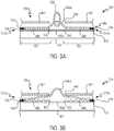
- first shoulder strap 126a is illustrated.
- the second shoulder strap 126b is omitted for simplicity of illustration. While the illustration of the second shoulder strap 126b is omitted from FIGS. 3A-3B , construction and operation of the second shoulder strap 126b is identical to that of the first shoulder strap 126a in the embodiment or aspect where both shoulder straps 126a, 126b incorporate the tubular webbing 147 and/or energy absorbing element.
- Each of the first shoulder strap 126a and a second shoulder strap 126b may have the tubular webbing 147 arranged to overlap one another in an X-shaped configuration.
- the tubular webbing 147 of the first shoulder strap 126a may have a first end that corresponds with the first end 127a of the first shoulder strap 126a (shown in FIG. 1 ).
- the first end of the tubular webbing 147 may be connected to the second end 110b of the belt strap 110 in a removably or non-removably attachable manner.
- the first end of the tubular webbing 147 may be attachable to the second end 110b of the belt strap 110 via a connector similar to the connector 104 described herein with reference to the leg straps 102.
- the tubular webbing 147 further has a second end that corresponds to the second end 127b of the first shoulder strap 126a (shown in FIG. 1 ).
- the second end of the tubular webbing 147 may be connected to one of the two leg straps 102 in a removably or non-removably attachable manner.
- the tubular webbing 147 may be formed from webbing material that is woven into a tubular shape, or from flat webbing material wherein opposite lateral ends of the substantially flat webbing material are connected together to form the tubular shape of the tubular webbing 147.
- the tubular webbing 147 may have an internal diameter of about 1.27 cm (0.5 inches) to about 5.08 cm (2.0 inches). In various embodiments or aspects, a longitudinal length of the tubular webbing 147 may be between about 60.96 cm (24 inches) to about 228.6 cm (90 inches).
- the opening 149 in the tubular webbing 147 may be formed at a substantially intermediate point between the first end 127a and the second end 127b of the first shoulder strap 126a (and/or the second shoulder strap 126b). In some preferred and non-limiting embodiments or aspects, the opening 149 may be formed at a rear portion of the harness 100 at an upper portion of a user's back.
- the opening 149 allows the substantially flat webbing material 146 to be exposed such that the substantially flat webbing material 146 may be connected to the D-ring 138.
- the opening 149 may be formed as a slit in the tubular webbing 147 having a length between about 1.27 cm (0.5 inches) to about 5.08 cm (2.0 inches).
- the energy absorbing element e.g., the flat webbing material 146
- at least a portion of the energy absorbing element is configured to exit through the opening 149 of the tubular webbing 147 upon tearing, thereby facilitating the complete (if necessary) separation of the flat webbing material 146.
- the opening 149 may be reinforced wholly or partially around its edges to ensure that the tubular webbing 147 does not rip or tear during a fall event.
- the substantially flat webbing material 146 of the first shoulder strap 126a has two webbing components 146a, 146b (which may be load-bearing webbing components) that are woven together by binder threads 148.
- the webbing material 146 may have a plurality of load-bearing webbing components.
- the webbing components 146a, 146b may each be typically made from a two ply webbing material constructed from high tenacity polyester or nylon yarns.
- Each webbing component 146a, 146b may have a face ply and a back ply.
- the webbing components 146a, 146b may be superimposed over one another such that the back ply of one of the webbing components 146a, 146b is positioned over the face ply of the other of the webbing components 146a, 146b.
- the webbing components 146a, 146b and the binder threads 148 are woven together to constitute a single-piece webbing material, i.e., the first shoulder strap 126a and the second shoulder strap 126b.
- binder threads 148 as a means of integrally bonding the webbing components 146a, 146b together
- suitable bonding means such as hook-and-loop fasteners, adhesives, or other energy absorbing materials may also be used, either individually or in combination with the binder threads 148.
- the binder threads 148 When the energy absorbing element is activated, such as during a fall event, the binder threads 148 are configured to be torn upon experiencing a force in excess of a predetermined force, thereby allowing the two webbing components 146a, 146b to tear apart from each other, such as shown in FIG. 3B .
- the predetermined force (load) may be in the range of about 140.614 kg (310 lbs) to about 1020.583 kg (2,250 lbs)
- the binder threads 148 are configured to absorb energy (force) of a user falling during a fall event by fracturing (or tearing/separating) and allowing the webbing components 146a, 146b to separate from each other.
- the tearing of the binder threads 148 may be initiated by a minimum predetermined force (load), such as about 140.614 kg (310 lbs).
- load such as about 140.614 kg (310 lbs).
- the tearing of the binder threads 148, and a consequent separation of the webbing components 146a, 146b continues as long as the force on the harness 100 exceeds the minimum predetermined force and ends when either (1) the webbing components 146a, 146b reach an ending point; or (2) the force reduces to a point below the minimum predetermined force.
- the shoulder strap 124 may be configured to tear the webbing components 146a, 146b apart from each other due to breaking of the binder threads 148 at a constant force.
- the minimum predetermined force (load) required to break the binder threads 148 may be configurable by increasing or decreasing the density of the binder threads 148 per unit area, increasing or decreasing the width of the shoulder strap 124, increasing or decreasing the density of the binder threads 148 along a longitudinal length and/or a lateral length of the shoulder strap 124, and/or selecting a type of thread having specified strength characteristics.
- the webbing components 146a, 146b may be bound together by an adhesive, such as glue, that separates when reaching the minimum predetermined force or load. It is recognized that these adhesives may be specifically formulated to meet the separation requirements at the minimum predetermined force or load.
- the binder threads 148 may extend through at least a portion of a thickness of at least one of the webbing components 146a, 146b.
- the binder threads 148 may extend between the face ply and the back ply of each of the webbing components 146a, 146b.
- the binder threads 148 extend though the entire thickness of each of the webbing components 146a, 146b.
- the binder threads 148 may be woven in two or more rows 153 extending along a longitudinal length and/or a lateral length of the webbing components 146a, 146b.
- the rows 153 may be substantially parallel to each other, or intersect at least once with each other along the longitudinal length and/or the lateral length of the webbing components 146a, 146b.
- the binder threads 148 may be arranged in a plurality of thread groups 151 arranged in a pattern on the webbing components 146a, 146b.
- the density of thread groups 151 may be constant along the longitudinal length and/or the lateral length of the webbing components 146a, 146b.
- the webbing components 146a, 146b will separate from one another due to breaking of the binder threads 148 at a constant rate at a given force that exceeds the minimum predetermined force.
- the density of thread groups 151 may vary along the longitudinal length and/or the lateral length of the webbing components 146a, 146b, such as by increasing or decreasing the density of the thread groups 151. Accordingly, the webbing components 146a, 146a will separate from one another due to breaking of the binder threads 148 at an increasing or decreasing rate at a given force that exceeds the minimum predetermined force.
- the arrangement of the thread groups 151 may be selected to optimize the tear-away force required to break the binder threads 148 (or adhesive) during separation of the webbing components 146a, 146b from each other.
- the binder threads 148 extend continuously between the webbing components 146a, 146b in a sinusoidal manner.
- the binder threads 148 may be made from high tenacity polyester yarns, nylon, or other suitable materials.
- the tensile strength of the binder threads 148 is desirably selected to be less than that of the webbing components 146a, 146b to allow the binder threads 148 to tear without tearing the webbing components 146a, 146b.
- the first shoulder strap 126a may have a starting tear point 150 at which the two webbing components 146a, 146b are not bound by the binder threads 148.
- the starting tear point 150 may be defined at a substantially intermediate portion of the first shoulder strap 126a between the first end 127a and the second end 127b. After the starting tear point 150, the webbing components 146a, 146b are integrally woven together.
- the binder threads 148 start to fracture (or tear) at the starting tear point 150 and continue tearing along the longitudinal length of an energy absorbing area 152 of the shoulder strap 126 that ties the webbing components 146a, 146b with the binder threads 148.
- the binder threads 148 are configured to tear successively along the longitudinal length of the bound absorbing area 152 beginning from the starting tear point 150. The successive tearing of the binder threads 148 absorbs energy of the fall, thereby safely decelerating the user and reducing the shock transferred to the user's body as the user's weight is borne by the harness. Further, at least a portion of the webbing components 146a, 146b exit from the tubular webbing 147 through the opening 149.
- the first shoulder strap 126a may have an ending tear point 154 at an end of the energy absorbing area 152.
- the ending tear point 154 may have a reinforced area 156, such as by additional stitching, to prevent further tearing of the webbing components 146a, 146b.
- the two webbing components 146a, 146b support the user's weight, such as with one of the webbing components 146a, 146b being connected to the D-ring 138, and the other of the two webbing components 146a, 146b supporting the user's shoulders.
- the tearing of the two webbing components 146a, 146b due to breaking of the binder threads 148 may end prior to the ending tear point 154 if the force on the harness is reduced below the minimum predetermined force necessary to tear the binder threads 148.
- a harness 100 having such a shoulder strap 126 eliminates the need for a structural back-up strap as the tear tape maintains the static strength of structural webbing at full elongation (end of deployment shown in FIG. 5C ). In this manner, the harness 100 does not differ externally from a conventional harness without the energy absorbing element, but incorporates the beneficial energy absorption element integrated into the harness 100.
Claims (15)
- Harnais pouvant être porté ayant une pluralité de courroies comprenant :une première courroie d'épaule et une deuxième courroie d'épaule, au moins une courroie parmi la première courroie d'épaule et la deuxième courroie d'épaule comprenant un sanglage tubulaire ; etun élément absorbant l'énergie intégré avec au moins une courroie parmi la première courroie d'épaule et la deuxième courroie d'épaule,l'élément absorbant l'énergie étant au moins partiellement placé dans le sanglage tubulaire et comprenant un matériau de sanglage déchirable avec au moins deux composants de sanglage reliés configurés pour se déchirer l'un de l'autre lorsque la première courroie d'épaule et la deuxième courroie d'épaule sont soumises à une force qui dépasse un seuil prédéterminé pendant un évènement de chute.
- Harnais de la revendication 1, dans lequel l'élément absorbant l'énergie est exposé à partir du sanglage tubulaire au niveau d'une portion essentiellement intermédiaire d'au moins une courroie parmi la première courroie d'épaule et la deuxième courroie d'épaule entre la première extrémité et la deuxième extrémité de ladite au moins une courroie parmi la première courroie d'épaule et la deuxième courroie d'épaule.
- Harnais de la revendication 1 ou de la revendication 2, dans lequel l'élément absorbant l'énergie est exposé à partir du sanglage tubulaire au travers d'une ouverture dans le sanglage tubulaire.
- Harnais de la revendication 3, dans lequel au moins une portion de l'élément absorbant l'énergie est configurée pour sortir au travers de l'ouverture du sanglage tubulaire lors du déchirement.
- Harnais de l'une quelconque des revendications précédentes, dans lequel le sanglage tubulaire comprend un matériau de sanglage essentiellement plat ayant des extrémités latérales opposées connectées l'une à l'autre pour définir une forme tubulaire.
- Harnais de l'une quelconque des revendications précédentes, dans lequel lesdits au moins deux composants de sanglage reliés sont reliés par une pluralité de fils de liage.
- Harnais de la revendication 6, dans lequel la pluralité de fils de liage sont configurés pour se déchirer successivement dans une direction longitudinale d'au moins une courroie parmi la première courroie d'épaule et la deuxième courroie d'épaule lorsque ladite au moins une courroie parmi la première courroie d'épaule et la deuxième courroie d'épaule est soumise à la force qui dépasse le seuil prédéterminé.
- Harnais de la revendication 6 ou 7, dans lequel la pluralité de fils de liage s'étendent au travers d'au moins une portion d'une épaisseur desdits au moins deux composants de sanglage.
- Harnais de l'une quelconque des revendications 6 à 8, dans lequel la pluralité de fils de liage sont agencés en deux ou davantage de rangées essentiellement parallèles ou croisées s'étendant le long d'une longueur longitudinale ou d'une longueur latérale des composants de sanglage.
- Harnais de l'une quelconque des revendications 6 à 8, dans lequel la pluralité de fils de liage sont agencés en deux ou davantage de groupes de fils agencés selon un motif et espacés les uns des autres le long d'une longueur longitudinale ou d'une longueur latérale des composants de sanglage.
- Harnais de l'une quelconque des revendications précédentes, dans lequel le seuil prédéterminé est dans une plage allant d'environ 140,614 kg (310 lb) à environ 1 020,583 kg (2 250 lb).
- Harnais de la revendication 1, dans lequel lesdits au moins deux composants de sanglage sont reliés ensemble par un adhésif.
- Harnais de l'une quelconque des revendications précédentes, dans lequel la première courroie d'épaule et la deuxième courroie d'épaule ont une zone de début de déchirement au niveau d'une portion arrière où la paire de composants de sanglage reliés est détachée.
- Harnais de l'une quelconque des revendications précédentes, dans lequel la première courroie d'épaule et la deuxième courroie d'épaule ont un point de fin de déchirure ayant une zone renforcée configurée pour empêcher une séparation desdits au moins deux composants de sanglage reliés.
- Harnais de l'une quelconque des revendications précédentes, dans lequel l'élément absorbant l'énergie est situé sur une zone absorbant l'énergie au niveau d'une portion arrière d'au moins une courroie parmi la première courroie d'épaule et la deuxième courroie d'épaule.
Priority Applications (1)
| Application Number | Priority Date | Filing Date | Title |
|---|---|---|---|
| EP20189535.6A EP3782703A1 (fr) | 2016-12-12 | 2017-12-05 | Harnais à absorbeur d'énergie intégré |
Applications Claiming Priority (2)
| Application Number | Priority Date | Filing Date | Title |
|---|---|---|---|
| US15/376,233 US10799731B2 (en) | 2016-12-12 | 2016-12-12 | Harness with integrated energy absorber |
| PCT/US2017/064684 WO2018111624A1 (fr) | 2016-12-12 | 2017-12-05 | Harnais à absorbeur d'énergie intégré |
Related Child Applications (2)
| Application Number | Title | Priority Date | Filing Date |
|---|---|---|---|
| EP20189535.6A Division EP3782703A1 (fr) | 2016-12-12 | 2017-12-05 | Harnais à absorbeur d'énergie intégré |
| EP20189535.6A Division-Into EP3782703A1 (fr) | 2016-12-12 | 2017-12-05 | Harnais à absorbeur d'énergie intégré |
Publications (2)
| Publication Number | Publication Date |
|---|---|
| EP3551296A1 EP3551296A1 (fr) | 2019-10-16 |
| EP3551296B1 true EP3551296B1 (fr) | 2020-09-30 |
Family
ID=60991526
Family Applications (2)
| Application Number | Title | Priority Date | Filing Date |
|---|---|---|---|
| EP20189535.6A Pending EP3782703A1 (fr) | 2016-12-12 | 2017-12-05 | Harnais à absorbeur d'énergie intégré |
| EP17829772.7A Active EP3551296B1 (fr) | 2016-12-12 | 2017-12-05 | Harnais à absorbeur d'énergie intégré |
Family Applications Before (1)
| Application Number | Title | Priority Date | Filing Date |
|---|---|---|---|
| EP20189535.6A Pending EP3782703A1 (fr) | 2016-12-12 | 2017-12-05 | Harnais à absorbeur d'énergie intégré |
Country Status (4)
| Country | Link |
|---|---|
| US (1) | US10799731B2 (fr) |
| EP (2) | EP3782703A1 (fr) |
| CN (1) | CN110225783B (fr) |
| WO (1) | WO2018111624A1 (fr) |
Families Citing this family (12)
| Publication number | Priority date | Publication date | Assignee | Title |
|---|---|---|---|---|
| US10588361B2 (en) * | 2016-06-20 | 2020-03-17 | Crystal Ketterhagen | Protective garments with adjustable closure systems |
| FR3059241B1 (fr) * | 2016-11-30 | 2020-01-10 | Zedel | Harnais d'encordement integral |
| US10532267B2 (en) | 2017-05-05 | 2020-01-14 | Easton Diamond Sports, Llc | Harness with single-pull adjustment for sports chest protector |
| US11633634B2 (en) * | 2018-04-06 | 2023-04-25 | Msa Technology, Llc | Cut-resistant leading edge fall arrest system and method |
| US10874886B2 (en) * | 2018-07-26 | 2020-12-29 | Msa Technology, Llc | Energy absorber coil for safety harness |
| US11497948B2 (en) * | 2018-10-12 | 2022-11-15 | Msa Technology, Llc | Harness back plate and strap arrangement |
| CN110923895B (zh) * | 2019-11-11 | 2023-12-19 | 肇庆市鼎湖兴文塑胶五金制品有限公司 | 一种织带边缘收边的编织方法 |
| US11179584B2 (en) | 2019-12-17 | 2021-11-23 | Tethrd LLC | Contoured saddle assembly |
| US11850452B2 (en) | 2019-12-17 | 2023-12-26 | Tethrd LLC | Harness with continuous linemans loop |
| US11331233B1 (en) * | 2020-01-02 | 2022-05-17 | Taina Rodriguez | Patient turning device with removable windows |
| US11504556B2 (en) | 2020-01-07 | 2022-11-22 | Tethrd LLC | Bridge rope assembly |
| WO2021184280A1 (fr) | 2020-03-19 | 2021-09-23 | Honeywell International Inc. | Harnais pour dispositif antichute |
Citations (2)
| Publication number | Priority date | Publication date | Assignee | Title |
|---|---|---|---|---|
| US20130292219A1 (en) * | 2012-05-04 | 2013-11-07 | D B Industries, Inc. | Energy absorber |
| US9308402B2 (en) * | 2011-05-19 | 2016-04-12 | Zedel | Harness for preventing a fall and for improved suspension support |
Family Cites Families (48)
| Publication number | Priority date | Publication date | Assignee | Title |
|---|---|---|---|---|
| US1574672A (en) * | 1924-07-03 | 1926-02-23 | Mccarroll-Doull Clara | Safety harness for children |
| BE624601A (fr) | 1961-07-07 | |||
| US3444957A (en) * | 1967-12-13 | 1969-05-20 | Rose Mfg Co | Shock absorber for safety belt |
| US4518026A (en) | 1980-07-14 | 1985-05-21 | Garland Manufacturing Co. | Energy efficient garage door construction and the like |
| CA1197824A (fr) | 1983-05-06 | 1985-12-10 | Institut De Recherche En Sante Et En Securite Du Travail Du Quebec | Gilet de securite |
| DE8511916U1 (de) | 1985-04-22 | 1985-05-30 | Gebr. Wahlefeld GmbH & Co KG, 4150 Krefeld | Auffanggurt |
| US5113981A (en) * | 1989-10-19 | 1992-05-19 | Lantz Michael D | Safety line shock absorber |
| US5167263A (en) * | 1991-10-16 | 1992-12-01 | Kelen Steven I | Industrial high strength webbing |
| US5287943A (en) | 1992-01-03 | 1994-02-22 | Michael Bell | Dual connection lanyard for use in safety system |
| US5279386A (en) * | 1993-02-25 | 1994-01-18 | Cearley Richard R | Rescue harness |
| US6006860A (en) * | 1993-11-10 | 1999-12-28 | Bell; Michael | Safety harness or belt with fiber means to indicate shock loading |
| US6085802A (en) * | 1999-02-02 | 2000-07-11 | Silberberg; Abraham A. | Shock absorbing woven webbing |
| US6299040B1 (en) * | 1999-07-02 | 2001-10-09 | Buckingham Manufacturing Co., Inc. | Tear-away retaining lanyard |
| FR2796297B1 (fr) | 1999-07-16 | 2001-10-26 | Zedel | Harnais d'encordement a longe d'accrochage deportee |
| CA2357885C (fr) | 2001-09-28 | 2006-11-28 | Safety Direct Ltd. | Harnais de securite a anneau en d a l'avant |
| US7909137B2 (en) | 2002-06-20 | 2011-03-22 | Trophyline, Llc | Support harness |
| CA2455701C (fr) | 2003-01-24 | 2013-07-02 | Her Majesty The Queen In Right Of Canada, As Represented By The Minister Of National Defence | Utilisation d'une methode de protection croisee pour identifier de nouveaux vaccins experimentaux pouvant immuniser contre des agents infectieux |
| ITPG20030037A1 (it) * | 2003-07-03 | 2003-10-01 | Lanzi Srl | Intreccio tessile di fibra rigida e fibra elastica costituente trovato elestico originante una o piu' asole rigide. |
| US20050189169A1 (en) * | 2004-03-01 | 2005-09-01 | Hajime Tanaka | Shock absorbing lanyards |
| US8387749B2 (en) * | 2004-03-01 | 2013-03-05 | Ykk Corporation Of America | Shock absorbing fabric structures |
| US7237650B2 (en) * | 2004-05-19 | 2007-07-03 | D B Industries, Inc. | Tension device for use with a self-retracting lifeline |
| US20060102423A1 (en) * | 2004-07-12 | 2006-05-18 | Lang Tracy H | Safety harnesses |
| US20060048723A1 (en) * | 2004-09-07 | 2006-03-09 | Rohlf Bradley A | Shock absorbing safety harness |
| US20070023231A1 (en) | 2005-07-26 | 2007-02-01 | Gorman Patrick J | Lightweight safety harness |
| CA2619758C (fr) * | 2005-08-16 | 2012-05-08 | Ykk Corporation Of America | Sangles d'absorption d'energie |
| GB0525386D0 (en) | 2005-12-13 | 2006-01-18 | Dawson Brian | Safety harness |
| US20070209868A1 (en) * | 2006-03-07 | 2007-09-13 | D B Industries, Inc. | Safety harness with an integrated lanyard |
| WO2007134746A1 (fr) | 2006-05-24 | 2007-11-29 | Mammut Sports Group Ag | Frein de chute |
| EP2724752B1 (fr) | 2006-12-11 | 2017-03-29 | Checkmate Limited | Harnais anti-chute |
| US8459518B2 (en) * | 2007-09-02 | 2013-06-11 | Steven Demsky | Backpacks configured to utilize safety harnesses |
| CA2639425C (fr) | 2007-09-14 | 2013-12-10 | Nouvelle Hauteur Inc. | Cordon et necessaire de sauvetage pour descente comprenant un dispositif de commande pour descente d'urgence |
| DE202008007870U1 (de) * | 2008-06-12 | 2008-08-28 | Skylotec Gmbh | Verbindungsmittel für eine Absturzsicherung |
| US8651235B2 (en) * | 2008-12-26 | 2014-02-18 | Norman E. Wood | Controlled descent system with an increased recovery range |
| US8959664B2 (en) * | 2009-02-09 | 2015-02-24 | D B Industries, Llc | Harness webbing protection system |
| US8356691B2 (en) * | 2009-08-18 | 2013-01-22 | Sturges Manufacturing Co., Inc. | Energy absorber for personal fall arrestor |
| US9557138B2 (en) * | 2010-02-04 | 2017-01-31 | Savvy Sniper | Single to two point tactical sling |
| FR2969500B1 (fr) * | 2010-12-22 | 2013-01-25 | Zedel | Longe de securite et son procede de fabrication |
| DE102011003579A1 (de) | 2011-02-03 | 2012-08-09 | Aloys Wobben | Auffanggurt |
| US8584799B1 (en) * | 2011-06-28 | 2013-11-19 | Mark Dennington | Fall-arresting safety harness assembly |
| US20130105246A1 (en) * | 2011-10-28 | 2013-05-02 | D B Industries, Inc. | Energy absorber |
| US9027707B2 (en) | 2012-01-10 | 2015-05-12 | Honeywell International Inc. | Convertible safety harness |
| US9174073B2 (en) * | 2013-02-08 | 2015-11-03 | D B Industries, Llc | Energy absorber assembly and components thereof |
| CN203220697U (zh) * | 2013-03-28 | 2013-10-02 | 昆山彰茂航汽配件有限公司 | 新型y型织带缓冲器 |
| US9233585B1 (en) * | 2013-10-08 | 2016-01-12 | Tommy B. Haynes | Towing tie assembly |
| DE102013017680A1 (de) * | 2013-10-27 | 2015-04-30 | Renate Meckel | Fallsicherungssystem |
| CN203634684U (zh) * | 2013-11-22 | 2014-06-11 | 塞卡尔(北京)工业技术有限公司 | 一种一体式缓冲连接装置 |
| US9410766B1 (en) * | 2014-03-05 | 2016-08-09 | Jason M. Falla | Sling |
| FR3036037B1 (fr) | 2015-05-13 | 2017-05-26 | Zedel | Harnais d'encordement perfectionne |
-
2016
- 2016-12-12 US US15/376,233 patent/US10799731B2/en active Active
-
2017
- 2017-12-05 EP EP20189535.6A patent/EP3782703A1/fr active Pending
- 2017-12-05 WO PCT/US2017/064684 patent/WO2018111624A1/fr active Application Filing
- 2017-12-05 CN CN201780084520.7A patent/CN110225783B/zh active Active
- 2017-12-05 EP EP17829772.7A patent/EP3551296B1/fr active Active
Patent Citations (2)
| Publication number | Priority date | Publication date | Assignee | Title |
|---|---|---|---|---|
| US9308402B2 (en) * | 2011-05-19 | 2016-04-12 | Zedel | Harness for preventing a fall and for improved suspension support |
| US20130292219A1 (en) * | 2012-05-04 | 2013-11-07 | D B Industries, Inc. | Energy absorber |
Also Published As
| Publication number | Publication date |
|---|---|
| EP3782703A1 (fr) | 2021-02-24 |
| EP3551296A1 (fr) | 2019-10-16 |
| WO2018111624A1 (fr) | 2018-06-21 |
| US10799731B2 (en) | 2020-10-13 |
| US20180161607A1 (en) | 2018-06-14 |
| CN110225783B (zh) | 2021-08-17 |
| CN110225783A (zh) | 2019-09-10 |
Similar Documents
| Publication | Publication Date | Title |
|---|---|---|
| EP3551296B1 (fr) | Harnais à absorbeur d'énergie intégré | |
| EP3551297B1 (fr) | Harnais à bandelette structurale déchirable | |
| US10596397B2 (en) | Harness configurations for a suspension device | |
| US8584799B1 (en) | Fall-arresting safety harness assembly | |
| EP1740272B1 (fr) | Dispositifs, systemes et procedes pour la descente en urgence d'une hauteur | |
| CN112823041B (zh) | 具有可调节式腰带的保护带 | |
| US10821310B2 (en) | Harness with pivoting hip connection | |
| EP2431076A2 (fr) | Cordone absorbant les chocs | |
| CA3106842C (fr) | Bobine d'absorption d'energie pour harnais de securite | |
| US10335619B2 (en) | Firefighter multifunction ladder and escape belt | |
| JP2004141480A (ja) | ハーネス型安全帯 | |
| JP2020195518A (ja) | ランヤード | |
| JP2009172704A (ja) | 胴当てベルト | |
| KR20150003686U (ko) | 고소작업용 안전벨트 | |
| JP5102472B2 (ja) | 安全ベスト | |
| KR20180000411U (ko) | 고소작업용 안전벨트 |
Legal Events
| Date | Code | Title | Description |
|---|---|---|---|
| STAA | Information on the status of an ep patent application or granted ep patent |
Free format text: STATUS: UNKNOWN |
|
| STAA | Information on the status of an ep patent application or granted ep patent |
Free format text: STATUS: THE INTERNATIONAL PUBLICATION HAS BEEN MADE |
|
| PUAI | Public reference made under article 153(3) epc to a published international application that has entered the european phase |
Free format text: ORIGINAL CODE: 0009012 |
|
| STAA | Information on the status of an ep patent application or granted ep patent |
Free format text: STATUS: REQUEST FOR EXAMINATION WAS MADE |
|
| 17P | Request for examination filed |
Effective date: 20190613 |
|
| AK | Designated contracting states |
Kind code of ref document: A1 Designated state(s): AL AT BE BG CH CY CZ DE DK EE ES FI FR GB GR HR HU IE IS IT LI LT LU LV MC MK MT NL NO PL PT RO RS SE SI SK SM TR |
|
| AX | Request for extension of the european patent |
Extension state: BA ME |
|
| RIN1 | Information on inventor provided before grant (corrected) |
Inventor name: QUIGLEY, MATTHEW Inventor name: SEPE, BENJAMIN, T. Inventor name: JACOB, MATTHEW, FREDERICK |
|
| DAV | Request for validation of the european patent (deleted) | ||
| DAX | Request for extension of the european patent (deleted) | ||
| GRAP | Despatch of communication of intention to grant a patent |
Free format text: ORIGINAL CODE: EPIDOSNIGR1 |
|
| STAA | Information on the status of an ep patent application or granted ep patent |
Free format text: STATUS: GRANT OF PATENT IS INTENDED |
|
| INTG | Intention to grant announced |
Effective date: 20200518 |
|
| GRAS | Grant fee paid |
Free format text: ORIGINAL CODE: EPIDOSNIGR3 |
|
| GRAA | (expected) grant |
Free format text: ORIGINAL CODE: 0009210 |
|
| STAA | Information on the status of an ep patent application or granted ep patent |
Free format text: STATUS: THE PATENT HAS BEEN GRANTED |
|
| AK | Designated contracting states |
Kind code of ref document: B1 Designated state(s): AL AT BE BG CH CY CZ DE DK EE ES FI FR GB GR HR HU IE IS IT LI LT LU LV MC MK MT NL NO PL PT RO RS SE SI SK SM TR |
|
| REG | Reference to a national code |
Ref country code: GB Ref legal event code: FG4D Ref country code: CH Ref legal event code: EP |
|
| REG | Reference to a national code |
Ref country code: AT Ref legal event code: REF Ref document number: 1318195 Country of ref document: AT Kind code of ref document: T Effective date: 20201015 |
|
| REG | Reference to a national code |
Ref country code: DE Ref legal event code: R096 Ref document number: 602017024765 Country of ref document: DE |
|
| REG | Reference to a national code |
Ref country code: IE Ref legal event code: FG4D |
|
| PG25 | Lapsed in a contracting state [announced via postgrant information from national office to epo] |
Ref country code: BG Free format text: LAPSE BECAUSE OF FAILURE TO SUBMIT A TRANSLATION OF THE DESCRIPTION OR TO PAY THE FEE WITHIN THE PRESCRIBED TIME-LIMIT Effective date: 20201230 Ref country code: FI Free format text: LAPSE BECAUSE OF FAILURE TO SUBMIT A TRANSLATION OF THE DESCRIPTION OR TO PAY THE FEE WITHIN THE PRESCRIBED TIME-LIMIT Effective date: 20200930 Ref country code: SE Free format text: LAPSE BECAUSE OF FAILURE TO SUBMIT A TRANSLATION OF THE DESCRIPTION OR TO PAY THE FEE WITHIN THE PRESCRIBED TIME-LIMIT Effective date: 20200930 Ref country code: HR Free format text: LAPSE BECAUSE OF FAILURE TO SUBMIT A TRANSLATION OF THE DESCRIPTION OR TO PAY THE FEE WITHIN THE PRESCRIBED TIME-LIMIT Effective date: 20200930 Ref country code: NO Free format text: LAPSE BECAUSE OF FAILURE TO SUBMIT A TRANSLATION OF THE DESCRIPTION OR TO PAY THE FEE WITHIN THE PRESCRIBED TIME-LIMIT Effective date: 20201230 Ref country code: GR Free format text: LAPSE BECAUSE OF FAILURE TO SUBMIT A TRANSLATION OF THE DESCRIPTION OR TO PAY THE FEE WITHIN THE PRESCRIBED TIME-LIMIT Effective date: 20201231 |
|
| REG | Reference to a national code |
Ref country code: AT Ref legal event code: MK05 Ref document number: 1318195 Country of ref document: AT Kind code of ref document: T Effective date: 20200930 |
|
| PG25 | Lapsed in a contracting state [announced via postgrant information from national office to epo] |
Ref country code: RS Free format text: LAPSE BECAUSE OF FAILURE TO SUBMIT A TRANSLATION OF THE DESCRIPTION OR TO PAY THE FEE WITHIN THE PRESCRIBED TIME-LIMIT Effective date: 20200930 Ref country code: LV Free format text: LAPSE BECAUSE OF FAILURE TO SUBMIT A TRANSLATION OF THE DESCRIPTION OR TO PAY THE FEE WITHIN THE PRESCRIBED TIME-LIMIT Effective date: 20200930 |
|
| REG | Reference to a national code |
Ref country code: NL Ref legal event code: MP Effective date: 20200930 |
|
| REG | Reference to a national code |
Ref country code: LT Ref legal event code: MG4D |
|
| PG25 | Lapsed in a contracting state [announced via postgrant information from national office to epo] |
Ref country code: SM Free format text: LAPSE BECAUSE OF FAILURE TO SUBMIT A TRANSLATION OF THE DESCRIPTION OR TO PAY THE FEE WITHIN THE PRESCRIBED TIME-LIMIT Effective date: 20200930 Ref country code: LT Free format text: LAPSE BECAUSE OF FAILURE TO SUBMIT A TRANSLATION OF THE DESCRIPTION OR TO PAY THE FEE WITHIN THE PRESCRIBED TIME-LIMIT Effective date: 20200930 Ref country code: CZ Free format text: LAPSE BECAUSE OF FAILURE TO SUBMIT A TRANSLATION OF THE DESCRIPTION OR TO PAY THE FEE WITHIN THE PRESCRIBED TIME-LIMIT Effective date: 20200930 Ref country code: PT Free format text: LAPSE BECAUSE OF FAILURE TO SUBMIT A TRANSLATION OF THE DESCRIPTION OR TO PAY THE FEE WITHIN THE PRESCRIBED TIME-LIMIT Effective date: 20210201 Ref country code: RO Free format text: LAPSE BECAUSE OF FAILURE TO SUBMIT A TRANSLATION OF THE DESCRIPTION OR TO PAY THE FEE WITHIN THE PRESCRIBED TIME-LIMIT Effective date: 20200930 Ref country code: EE Free format text: LAPSE BECAUSE OF FAILURE TO SUBMIT A TRANSLATION OF THE DESCRIPTION OR TO PAY THE FEE WITHIN THE PRESCRIBED TIME-LIMIT Effective date: 20200930 |
|
| PG25 | Lapsed in a contracting state [announced via postgrant information from national office to epo] |
Ref country code: AL Free format text: LAPSE BECAUSE OF FAILURE TO SUBMIT A TRANSLATION OF THE DESCRIPTION OR TO PAY THE FEE WITHIN THE PRESCRIBED TIME-LIMIT Effective date: 20200930 Ref country code: AT Free format text: LAPSE BECAUSE OF FAILURE TO SUBMIT A TRANSLATION OF THE DESCRIPTION OR TO PAY THE FEE WITHIN THE PRESCRIBED TIME-LIMIT Effective date: 20200930 Ref country code: ES Free format text: LAPSE BECAUSE OF FAILURE TO SUBMIT A TRANSLATION OF THE DESCRIPTION OR TO PAY THE FEE WITHIN THE PRESCRIBED TIME-LIMIT Effective date: 20200930 Ref country code: PL Free format text: LAPSE BECAUSE OF FAILURE TO SUBMIT A TRANSLATION OF THE DESCRIPTION OR TO PAY THE FEE WITHIN THE PRESCRIBED TIME-LIMIT Effective date: 20200930 Ref country code: IS Free format text: LAPSE BECAUSE OF FAILURE TO SUBMIT A TRANSLATION OF THE DESCRIPTION OR TO PAY THE FEE WITHIN THE PRESCRIBED TIME-LIMIT Effective date: 20210130 |
|
| PG25 | Lapsed in a contracting state [announced via postgrant information from national office to epo] |
Ref country code: SK Free format text: LAPSE BECAUSE OF FAILURE TO SUBMIT A TRANSLATION OF THE DESCRIPTION OR TO PAY THE FEE WITHIN THE PRESCRIBED TIME-LIMIT Effective date: 20200930 Ref country code: NL Free format text: LAPSE BECAUSE OF FAILURE TO SUBMIT A TRANSLATION OF THE DESCRIPTION OR TO PAY THE FEE WITHIN THE PRESCRIBED TIME-LIMIT Effective date: 20200930 |
|
| REG | Reference to a national code |
Ref country code: DE Ref legal event code: R097 Ref document number: 602017024765 Country of ref document: DE |
|
| REG | Reference to a national code |
Ref country code: CH Ref legal event code: PL |
|
| PLBE | No opposition filed within time limit |
Free format text: ORIGINAL CODE: 0009261 |
|
| STAA | Information on the status of an ep patent application or granted ep patent |
Free format text: STATUS: NO OPPOSITION FILED WITHIN TIME LIMIT |
|
| PG25 | Lapsed in a contracting state [announced via postgrant information from national office to epo] |
Ref country code: DK Free format text: LAPSE BECAUSE OF FAILURE TO SUBMIT A TRANSLATION OF THE DESCRIPTION OR TO PAY THE FEE WITHIN THE PRESCRIBED TIME-LIMIT Effective date: 20200930 Ref country code: MC Free format text: LAPSE BECAUSE OF FAILURE TO SUBMIT A TRANSLATION OF THE DESCRIPTION OR TO PAY THE FEE WITHIN THE PRESCRIBED TIME-LIMIT Effective date: 20200930 |
|
| REG | Reference to a national code |
Ref country code: BE Ref legal event code: MM Effective date: 20201231 |
|
| 26N | No opposition filed |
Effective date: 20210701 |
|
| PG25 | Lapsed in a contracting state [announced via postgrant information from national office to epo] |
Ref country code: IE Free format text: LAPSE BECAUSE OF NON-PAYMENT OF DUE FEES Effective date: 20201205 Ref country code: LU Free format text: LAPSE BECAUSE OF NON-PAYMENT OF DUE FEES Effective date: 20201205 Ref country code: IT Free format text: LAPSE BECAUSE OF FAILURE TO SUBMIT A TRANSLATION OF THE DESCRIPTION OR TO PAY THE FEE WITHIN THE PRESCRIBED TIME-LIMIT Effective date: 20200930 |
|
| PG25 | Lapsed in a contracting state [announced via postgrant information from national office to epo] |
Ref country code: SI Free format text: LAPSE BECAUSE OF FAILURE TO SUBMIT A TRANSLATION OF THE DESCRIPTION OR TO PAY THE FEE WITHIN THE PRESCRIBED TIME-LIMIT Effective date: 20200930 Ref country code: CH Free format text: LAPSE BECAUSE OF NON-PAYMENT OF DUE FEES Effective date: 20201231 Ref country code: LI Free format text: LAPSE BECAUSE OF NON-PAYMENT OF DUE FEES Effective date: 20201231 |
|
| PG25 | Lapsed in a contracting state [announced via postgrant information from national office to epo] |
Ref country code: IS Free format text: LAPSE BECAUSE OF FAILURE TO SUBMIT A TRANSLATION OF THE DESCRIPTION OR TO PAY THE FEE WITHIN THE PRESCRIBED TIME-LIMIT Effective date: 20210130 Ref country code: TR Free format text: LAPSE BECAUSE OF FAILURE TO SUBMIT A TRANSLATION OF THE DESCRIPTION OR TO PAY THE FEE WITHIN THE PRESCRIBED TIME-LIMIT Effective date: 20200930 Ref country code: MT Free format text: LAPSE BECAUSE OF FAILURE TO SUBMIT A TRANSLATION OF THE DESCRIPTION OR TO PAY THE FEE WITHIN THE PRESCRIBED TIME-LIMIT Effective date: 20200930 Ref country code: CY Free format text: LAPSE BECAUSE OF FAILURE TO SUBMIT A TRANSLATION OF THE DESCRIPTION OR TO PAY THE FEE WITHIN THE PRESCRIBED TIME-LIMIT Effective date: 20200930 |
|
| PG25 | Lapsed in a contracting state [announced via postgrant information from national office to epo] |
Ref country code: MK Free format text: LAPSE BECAUSE OF FAILURE TO SUBMIT A TRANSLATION OF THE DESCRIPTION OR TO PAY THE FEE WITHIN THE PRESCRIBED TIME-LIMIT Effective date: 20200930 |
|
| PG25 | Lapsed in a contracting state [announced via postgrant information from national office to epo] |
Ref country code: BE Free format text: LAPSE BECAUSE OF NON-PAYMENT OF DUE FEES Effective date: 20201231 |
|
| REG | Reference to a national code |
Ref country code: DE Ref legal event code: R082 Ref document number: 602017024765 Country of ref document: DE Representative=s name: JONES DAY RECHTSANWAELTE PATENTANWAELTE, DE |
|
| P01 | Opt-out of the competence of the unified patent court (upc) registered |
Effective date: 20230626 |
|
| PGFP | Annual fee paid to national office [announced via postgrant information from national office to epo] |
Ref country code: FR Payment date: 20230929 Year of fee payment: 7 |
|
| PGFP | Annual fee paid to national office [announced via postgrant information from national office to epo] |
Ref country code: GB Payment date: 20231012 Year of fee payment: 7 |
|
| PGFP | Annual fee paid to national office [announced via postgrant information from national office to epo] |
Ref country code: DE Payment date: 20231010 Year of fee payment: 7 |