EP3551117B1 - Bildgeführte bewegungsskalierung für eine robotersteuerung - Google Patents
Bildgeführte bewegungsskalierung für eine robotersteuerung Download PDFInfo
- Publication number
- EP3551117B1 EP3551117B1 EP17828659.7A EP17828659A EP3551117B1 EP 3551117 B1 EP3551117 B1 EP 3551117B1 EP 17828659 A EP17828659 A EP 17828659A EP 3551117 B1 EP3551117 B1 EP 3551117B1
- Authority
- EP
- European Patent Office
- Prior art keywords
- motion
- surgical robotic
- robotic arm
- scale
- image guided
- Prior art date
- Legal status (The legal status is an assumption and is not a legal conclusion. Google has not performed a legal analysis and makes no representation as to the accuracy of the status listed.)
- Active
Links
Images


Classifications
-
- A—HUMAN NECESSITIES
- A61—MEDICAL OR VETERINARY SCIENCE; HYGIENE
- A61B—DIAGNOSIS; SURGERY; IDENTIFICATION
- A61B34/00—Computer-aided surgery; Manipulators or robots specially adapted for use in surgery
- A61B34/70—Manipulators specially adapted for use in surgery
- A61B34/77—Manipulators with motion or force scaling
-
- A—HUMAN NECESSITIES
- A61—MEDICAL OR VETERINARY SCIENCE; HYGIENE
- A61B—DIAGNOSIS; SURGERY; IDENTIFICATION
- A61B34/00—Computer-aided surgery; Manipulators or robots specially adapted for use in surgery
- A61B34/30—Surgical robots
-
- A—HUMAN NECESSITIES
- A61—MEDICAL OR VETERINARY SCIENCE; HYGIENE
- A61B—DIAGNOSIS; SURGERY; IDENTIFICATION
- A61B34/00—Computer-aided surgery; Manipulators or robots specially adapted for use in surgery
- A61B34/30—Surgical robots
- A61B34/37—Leader-follower robots
-
- B—PERFORMING OPERATIONS; TRANSPORTING
- B25—HAND TOOLS; PORTABLE POWER-DRIVEN TOOLS; MANIPULATORS
- B25J—MANIPULATORS; CHAMBERS PROVIDED WITH MANIPULATION DEVICES
- B25J9/00—Program-controlled manipulators
- B25J9/16—Program controls
- B25J9/1694—Program controls characterised by use of sensors other than normal servo-feedback from position, speed or acceleration sensors, perception control, multi-sensor controlled systems, sensor fusion
- B25J9/1697—Vision controlled systems
Definitions
- the inventions of the present disclosure generally relate to surgical robotic systems incorporating motion scales within the control of one or more surgical robotic arms (e.g., the da Vinci ® Surgical System, the Raven Robotic Surgical System, the Sport TM Surgical System, the Flex TM Robotic System, etc.).
- the inventions of the present disclosure more particularly relate to improving such surgical robotic systems by incorporating an image guided motion scaling within the control of surgical robotic arm(s).
- WO 2016/028858 A1 describes a method of using a control system or controlling a medical instrument within a patient anatomy that comprises localizing the medical instrument relative to the patient anatomy and identifying an environmental factor for the localized medical instrument.
- Surgical robotic systems today are controlled from a surgeon console. More particularly, an operator moves handles on the console whereby a signal from the handles is interpreted and translated into the motion of a surgical robotic arm. This motion may be scaled so that a motion of a robot end-effector is smaller or larger than the motion of the handles or operator's hands.
- the scaling factor is defined by the surgical robotic system or by the operator of the system. For example, the operator may define the scaling factor as 5: 1, which means a motion defined by the handles of the surgeon console is reduced 5x for the corresponding motion of the robot end-effector.
- the scaling factor facilitates an improvement in a precision of a surgical robotic procedure by allowing console operators to perform very delicate procedures (e.g., suturing a small vessel) with large handle motion that is more intuitive and by scaling down any operator tremor applied to the handles.
- the scaling factor may be effectuated via a voice recognition system, control buttons or the like, and may be set differently for different surgical robotic arms and along different directions. Nonetheless, a setting of a scaling factor is subjective and it is fixed until the console operator decides to modify the scaling factor. Additionally, the current subjective setting of a scaling factor fails to effectively account for the surgical environment and is therefore independent of a proximity of a robotic end-effector to critical structures or tissue or to other robotic arms.
- one issue is a constant scaling factor may lead to surgical complications. For example, if the scaling factor is set to amplify a motion of a robotic arm and a console operator gets close to a forbidden zone of an anatomical region, then a reaction time of the console operator may not be sufficient to stop or slow down the approach of the surgical robotic arm to the forbidden zone, which may lead to injury. Also, in some cases, another issue is a surgical task may require fine motion in one area of the anatomical region and fast motion in another area of the anatomical region.
- tissue is to be removed (e.g., resection of a tumor or milling of bone)
- a fast, large motion may be desirable in free space of the anatomical region while a fine or slow motion might be required close to the tissue boundaries.
- frequent changes of the scaling factor by the console operator to address these issues may distract from the surgical robotic task.
- the present disclosure provides inventions for defining a motion scale of a surgical robotic arm from a pre-operative imaging and/or an intra-operative imaging of the anatomical region (e.g., a endoscopic/laparoscopic image, an X-ray image, a computed-tomography image, an ultrasound image, a magnetic resonance image, etc.).
- the motion scale is at least based on the position of the surgical robotic arm but can additionally also be based on any parameter related to the motion of a surgical robotic arm within the surgical coordinate space including, but not limited to, a speed of the surgical robotic arm within the surgical coordinate space.
- the improvement by the inventions of the present disclosure is the motion scale will depend on the environment in which the surgical robotic arm is operating and allow for improved handling by facilitating a reduction in a risk to patient injury and a reduction in surgical procedure time.
- One embodiment of the inventions of the present disclosure is an image guided motion scaled surgical robotic system employing a surgical robotic arm and an image guided motion scaled robot controller.
- image guided motion scaled robot controller controls an actuated motion of the surgical robotic arm within the anatomical region based on a map of a motion scale delineated within an imaging of the anatomical region.
- a second embodiment of the inventions of the present disclosure is the image guided motion scaled robot controller employing application modules including a motion vector generator and a surgical robotic arm actuator.
- the motion vector generator generates a motion vector signal responsive to an input signal indicative of a user defined motion of the surgical robotic arm within the anatomical region, the motion vector signal being indicative of an actuated motion of a surgical robotic arm within the anatomical region.
- the generation of the motion vector signal by the motion vector generator may be based on the map of the motion scale delineated within the imaging of the anatomical region.
- the surgical robotic arm actuator structurally generates actuation commands instructive of the actuated motion of the surgical robotic arm within the anatomical region.
- the generation of the actuation commands by the surgical robotic arm actuator may be based on the map of the motion scale delineated within the imaging of the anatomical region.
- a third form embodiment of the inventions of the present disclosure is an image guided motion scaled robot control computer program product implemented by the image guided motion scaled surgical robotic system.
- the image guided motion scaled robot control method of the computer program product involves the image guided motion scaled robot controller receiving an input signal indicative of a user defined motion of the surgical robotic arm within the anatomical region.
- the image guided motion scaled robot control method of the computer program product further involves the image guided motion scaled robot controller, responsive to the input signal, controlling a actuated motion of the surgical robotic arm within the anatomical region based on the map of the motion scale delineated within the imaging of the anatomical region.
- a motion scale of the present disclosure encompasses a planar area or a volumetric area mapped within an imaging of an anatomical region whereby a scaling factor is applied to a user defined motion of a surgical robotic arm within the anatomical region to thereby control an actuated motion of the surgical robotic arm within the anatomical region with the actuated motion of the surgical robotic arm being an attenuation or an amplification of the user defined motion.
- a motion scale of the present disclosure includes one or more scaling factors.
- a scaling factor of the present disclosure may be a ratio of SF ATT :1 quantifying an attenuation of the user defined motion in controlling the motion of the surgical robotic arm within the anatomical region, or may be ratio of 1:SF AMP quantifying an amplification of the user defined motion in controlling the motion of the surgical robotic arm within the anatomical region.
- a scaling factor of 5:1 quantifies an attenuation of the user defined motion by 5x in controlling the motion of the surgical robotic arm within the anatomical region
- a scaling factor of 1:5 quantifies an amplification of the user defined motion by 5x in controlling the motion of the surgical robotic arm within the anatomical region.
- a motion scale of the present disclosure may have a single scaling factor for an entirety of the planar area or the volumetric area within the imaging coordinate space.
- the single scaling factor may be a fixed attenuation ratio or a fixed amplification ratio throughout the entirety of the planar area or the volumetric area.
- the single scaling factor may be a variable attenuation ratio or a variable amplification ratio throughout the entirety of the of the planar area or the volumetric area within the imaging coordinate space.
- the scaling factor may quantify a positive sloping or a negative sloping attenuation or amplification of the user defined motion across the planar area or the volumetric area in controlling the motion of the surgical robotic arm within the surgical coordinate space.
- the scaling factor may quantify a conditional attenuation or a conditional amplification of the user defined motion across the planar area or the volumetric area in controlling the motion of the surgical robotic arm within the anatomical region based on characteristics of the surgical environment including, but not limited to, (1) an increase or a decrease in the scaling factor as a function of a positioning of one or more surgical robotic arms within the anatomical region relative to a positioning of an anatomical structure illustrated within the imaging of the anatomical region, and (2) an increase or a decrease in the scaling factor as a function of a relative positioning of two surgical robotic arms within the anatomical region.
- a motion scale of the present disclosure may encompass a zoning of the planar area or the volumetric area within the imaging coordinate space whereby each zone has a different scaling factor that may be fixed or variable as previously described herein.
- a designated technique of the present disclosure for mapping a motion scale into the image coordinate space may be in accordance with a particular type of surgical robotic procedure to be performed on the anatomical region and/or a particular type of imaging of the anatomical region (e.g., a endoscopic/laparoscopic image, an X-ray image, a computed-tomography image, an ultrasound image, a magnetic resonance image, etc.).
- a particular type of surgical robotic procedure to be performed on the anatomical region and/or a particular type of imaging of the anatomical region (e.g., a endoscopic/laparoscopic image, an X-ray image, a computed-tomography image, an ultrasound image, a magnetic resonance image, etc.).
- FIGS. 1-4 teaches basic inventive principles of a graphical delineation mapping of a motion scale within an imaging coordinate space in accordance with the inventive principles of the present disclosure. From this description of FIGS. 1-4 , those having ordinary skill in the art will appreciate how to apply the inventive principles of the present disclosure to practice numerous and various embodiments of a graphical delineation mapping of a motion scale within an imaging coordinate space.
- a motion scale in accordance with the inventive principles of the present disclosure may be derived from a graphical delineation of a mapping of the motion scale within an imaging coordinate space of the imaging of an anatomical region.
- the graphical delineation may be performed in accordance with known image processing techniques for delineating graphical objects within an imaging coordinate space including, but not limited to, path planning techniques for delineating a planned surgical path within an imaging of the anatomical region.
- a delineation of a mapping of the motion scale within the imaging of the anatomical region may be facilitated by a graphical user interface providing for a user delineation of a planar area or a volumetric area within the imaging of the anatomical region, particularly relative to any anatomical structure illustrated within or segmented from the imaging of the anatomical region.
- the imaging of the anatomical region may be a two-dimensional ("2D") anatomical imaging or a three-dimensional ("3D") anatomical imaging performed during a pre-operative phase and/or an intra-operative phase of a surgical robotic procedure, and may be performed by any type of the imaging modality applicable to the surgical robotic procedure (e.g., a endoscopic/laparoscopic image, an X-ray image, a computed-tomography image, an ultrasound image, a magnetic resonance image, etc.).
- a motion scale of the present disclosure may represent one or more parameters related to the motion of a surgical robotic arm within the anatomical region including, but not limited:
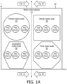
- FIG. 1A illustrates motion scale mapping 11 of a plurality of motion scales 20, 30, 40, 50 of the present disclosure delineated within an anatomical image space 10 outlining an imaging of an anatomical region, of which anatomical structures of the anatomical region are not shown for clarity.
- motion scales 20, 30, 40, 50 may encompass a planar area as shown in FIG. 1A for two-dimensional ("2D") imaging of the anatomical region (e.g., endoscopic/laparoscopic imaging or ultrasound imaging)
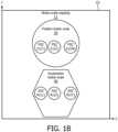
- motion scales 20, 30, 40, 50 may encompass a volumetric area as respectively shown in FIGS. 1B and 1C for three-dimensional (“3D”) imaging (e.g., CT imaging, MRI imaging and X-ray imaging).
- 2D two-dimensional
- 3D three-dimensional
- planar arear or the volumetric area of a mapped motion scale of the present disclosure may have any geometric shape, regular or irregular, including, but not limited to, a circular shape of position motion scale 20 as shown in FIGS. 1A and 1B , a square shape of velocity motion scale 30 as shown in FIGS. 1A and 1C , a hexagonal shape of acceleration motion scale 40 as shown in FIGS. 1A and 1B and an octagonal shape of force motion scale 50 as shown in FIGS. 1A and 1C .
- a user defined motion of a surgical robotic arm within an anatomical region is generated by a user input device of a surgical robotic arm as known in the art of the present disclosure (e.g., handle(s), joystick(s), roller ball(s), etc). More particularly, the user input device communicates an input signal indicative of a motion parameter directed to controlling a motion of the surgical robotic arm within the anatomical region.
- position motion scale 20 For an input signal indicative of a user defined positioning of a surgical robotic arm within an anatomical region ("positioning input signal”), position motion scale 20 provides a scaling of the positioning input signal to a positioning motion of a surgical robotic arm within the anatomical region.
- the positioning input signal may indicate a translation, a rotation and/or a pivoting of the surgical robotic arm within the anatomical region whereby position motion scale 20 provides for an attenuation or an amplification of the indicated translation, a rotation and/or a pivoting of the surgical robotic arm within the anatomical region to thereby control a translation, a rotation and/or a pivoting of the surgical robotic arm within the surgical coordinate space encircling the anatomical region.
- position motion scale 20 may include a single scaling factor that is fixed or variable throughout position motion scale 20.
- position motion scale may be divided into a W number of position scaling zones 21, W ⁇ 2, with each position scaling zone 21 having a different scaling factor that is fixed or variable throughout that particular position scaling zone 21.
- a size and a shape each position scaling zone 21 may be or may not be identical to another position scaling zone 21.
- velocity motion scale 30 For an input signal indicative of a user defined velocity of a surgical robotic arm within an anatomical region ("velocity input signal”), velocity motion scale 30 provides a scaling of the velocity input signal to a velocity motion of the surgical robotic arm within the anatomical region.
- the velocity input signal may indicate a desired velocity of a pre-defined translation, rotation and/or pivoting of the surgical robotic arm within the anatomical region whereby velocity motion scale 30 provides for an attenuation or an amplification of the indicated velocity of the pre-defined translation, rotation and/or pivoting of the surgical robotic arm within the anatomical region to thereby control the velocity of the predefined translation, rotation and/or pivoting of the surgical robotic arm within a surgical coordinate space encircling the anatomical region.
- velocity motion scale 30 may include a single scaling factor that is fixed or variable throughout velocity motion scale 30.
- velocity motion scale may be divided into a X number of velocity scaling zones 31, X ⁇ 2, with each velocity scaling zone 31 having a different scaling factor that is fixed or variable throughout that velocity scaling zone 31.
- a size and a shape each velocity scaling zone 31 may be or may not be identical to another velocity scaling zone 31.
- acceleration motion scale 40 For an input signal indicative of a user defined acceleration of a surgical robotic arm within an anatomical region ("acceleration input signal”), acceleration motion scale 40 provides a scaling of the acceleration input signal to an acceleration motion of the surgical robotic arm within the anatomical region.
- the acceleration input signal may indicate a desired acceleration of a pre-defined translation, rotation and/or pivoting of the surgical robotic arm within the anatomical region whereby acceleration motion scale 40 provides for an attenuation or an amplification of the indicated acceleration of the pre-defined translation, rotation and/or pivoting of the surgical robotic arm within the anatomical region to thereby control the acceleration of a predefined translation, rotation and/or pivoting of the surgical robotic arm within a surgical coordinate space encircling the anatomical region.
- acceleration motion scale 40 may include a single scaling factor that is fixed or variable throughout acceleration motion scale 40.
- acceleration motion scale may be divided into a Y number of acceleration scaling zones 41, Y ⁇ 2, with each acceleration scaling zone 41 having a different scaling factor that is fixed or variable throughout that acceleration scaling zone 41.
- a size and a shape each acceleration scaling zone 41 may be or may not be identical to another acceleration scaling zone 41.
- force motion scale 50 For the position input signal, the velocity input signal or the acceleration input signal, force motion scale 50 provides a scaling of the force applied to the user input device required to move the surgical robotic arm within a surgical coordinate space in accordance with the position input signal, the velocity input signal or the acceleration input signal. For example, force motion scale 50 provides for an attenuation or an amplification of the force applied to the user input device required to move the surgical robotic arm within a surgical coordinate space in accordance with the position input signal, the velocity input signal or the acceleration input signal.
- force motion scale 50 may include a single scaling factor that is fixed or variable throughout force motion scale 50.
- force motion scale may be divided into a Z number of force scaling zones 51, Z ⁇ 2, with each force scaling zone 51 has a different scaling factor that is fixed or variable throughout that force scaling zone 51.
- a size and a shape each force scaling zone 51 may be or may not be identical to another force scaling zone 51.
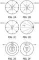
- FIGS. 2A-2F illustrates various exemplary scaling factors of mapped motion scales embodiments of the present disclosure. While FIGS. 2A-2F are described in the context of position motion scale 20 ( FIG. 1 ), those having ordinary skill in the art will appreciate how to apply the inventive principles of the present disclosure to practice numerous and various embodiments of scaling factors of mapped motion scales embodiments of the present disclosure.
- FIG. 2A illustrates a radial scaling factor 22a having a fixed attenuation or a fixed amplification of a user defined motion as symbolized by the bi-directional arrows within position motion scale 20a or a position scale zone 21a.
- the center of position motion scale 20a or positon scale zone 21a may represent a targeted location or an entry location of the surgical robotic arm within an anatomical region.
- FIG. 2B illustrates a radial scaling factor 22b having a variable attenuation of a user defined motion as symbolized by the uni-directional arrows within position motion scale 20b or a position scale zone 21b.
- the center of position motion scale 20b or positon scale zone 21b may represent a targeted location of the surgical robotic arm within an anatomical region.
- FIG. 2C illustrates a radial scaling factor 22c having a variable amplification of a user defined motion as symbolized by the uni-directional arrows within position motion scale 20c or a position scale zone 21c.
- the center of position motion scale 20c or positon scale zone 21c may represent an entry location of the surgical robotic arm within an anatomical region.
- FIG. 2D illustrates a chord scaling factor 23 having a variable amplification of a user defined motion as symbolized by the uni-directional arrows within position motion scale 20d or a position scale zone 21d.
- an endpoint of the chords scale 20d or positon scale zone 21d may represent a targeted location of the surgical robotic arm within an anatomical region.
- FIG. 2E illustrates a trio of concentric scaling factors 24-26 representative of three (3) scaling zones of a position motion scale 21e.
- Each scaling factor 24-26 has a different fixed or variable attenuation or amplification of a user defined motion.
- the center of the position scaling zones may represent a targeted location or an entry location of the surgical robotic arm within an anatomical region.
- FIG. 2F illustrates three (3) scaling zones of a positon motion scale 21f including a scaling factor 27 encircled by semi-hemisphere scaling factors 28 and 29.
- Each scaling factor 27-29 has a different fixed or variable attenuation or amplification of a user defined motion.
- the center of the position scaling zones may represent a targeted location or an entry location of the surgical robotic arm within an anatomical region.
- a surgical robotic procedure may involve a pre-operative endoscopic view and an intra-operative endoscopic view of an anatomical structure.
- the following is a description of an image guided motion scaled robot control of the present disclosure involving a pre-operative endoscopic view and an intra-operative endoscopic view of an anatomical structure.
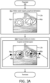
- a flowchart 60 represents an image guided motion scaled robot control of the present disclosure involving an a pre-operative endoscopic view 12a and an intra-operative endoscopic view 12b of a heart.
- a surgical robotic arm holding an endoscope is positioned via a user input device within a surgical coordinate space encircling a cardiac region to acquire pre-operative endoscopic view 12a of the heart. Thereafter, for an intra-operative phase of the surgical robotic procedure, the endoscope is held in or repositioned to the same pre-operative position to acquire an intra-operative endoscopic view 12b of a heart.
- stage S62 of flowchart 60 encompasses a motion scale mapping of a motion scale 70p and a motion scale 80p within an image coordinate space of pre-operative endoscopic view 12a of the heart.
- stage S62 may involve a calibration of the endoscope holding surgical robotic arm and a field of view of the endoscope, and a tracking of the surgical robotic arm within the surgical coordinate space (e.g., an electromagnetic tracking, an optical tracking, a Fiber-Optic RealShape ("FORS”) sensor tracking, and encoded joint tracking). From the calibration and tracking, the endoscope holding surgical robotic arm is actuated via a user input device to a desired field of view of the endoscope for the acquisition of pre-operative endoscopic view 12a of the heart.
- FORS Fiber-Optic RealShape
- motion scale 70p includes three (3) zones of scaling factors 71-73 covering a planar area as shown relative to the heart and motion scale 80p includes three (3) zones of scaling factors 81-83 covering a planar area as shown relative to the heart.
- motion scale 70p and motion scale 80p are delineated covering planar areas
- motion scale 70p and motion scale 80p may be positioned within the field of view of the endoscope at any depth, such as, for example, adjacent the heart as identified in pre-operative endoscopic view 12a of heart 12.
- motion scale 70p and motion scale 80p may cover a volumetric area extending through the field of view of the endoscope.
- a stage S64 of flowchart 60 encompasses an actuation of a pair of surgical robotic arms 90a and 90b via a user input device within a 3D surgical coordinate space 13 encircling the cardiac region.
- motion of end-effectors of surgical robotic arms 90a and 90b within surgical coordinate space 13 in accordance with a default motion setting is tracked (e.g., an electromagnetic tracking, an optical tracking, a FORS sensor tracking, and encoded joint tracking)
- motion scales 70p and 80p are applied to the default motion setting depending on the tracked positons of the end-effectors of surgical robotic arms 90a and 90b within surgical coordinate space 13 or image coordinate space 12b. the tracked positons of the end-effectors of surgical robotic arms 90a and 90b within surgical coordinate space 13 or image coordinate space 12b.
- a surgical robotic procedure may involve a pre-operative scanning and an intra-operative endoscopic view of an anatomical structure.
- the following is a description of an image guided motion scaled robot control of the present disclosure involving a pre-operative scanning and an intra-operative endoscopic view of an anatomical structure.
- a flowchart 100 represents an image guided motion scaled robot control of the present disclosure involving an a pre-operative scan 12c and an intra-operative endoscopic view 12d of a heart.
- an imaging system is used to scan the cardiac region to acquire pre-operative scan 12c of the heart (e.g., a CT, MRI or X-ray scan).
- pre-operative scan 12c of the heart e.g., a CT, MRI or X-ray scan.
- an endoscope may be positioned to acquire an intra-operative endoscopic view 12d of a heart whereby intra-operative endoscopic view 12d is fused with pre-operative scan 12c of the heart for display purposes as known in the art of the present disclosure.
- a stage S 102 of flowchart 100 encompasses a motion scale mapping of a motion scale 70p and a motion scale 80p within an image coordinate space of pre-operative scan 12c of the heart.
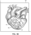
- stage S 102 may involve a segmentation of the heart within an image coordinate space 10b of pre-operative scan 12c as best shown in FIG. 4B .
- a graphical user interface (not shown) is provided for allowing a graphical delineation of motion scale 70v and motion scale 80v covering a volumetric area relative to the segmented heart.
- motion scale 70v includes three (3) zones of scaling factors covering a volumetric area as shown relative to the heart and motion scale 80v includes three (3) zones of scaling factors covering a volumetric area as shown relative to the heart.
- a stage S 104 of flowchart 100 encompasses an actuation of a pair of surgical robotic arms 90a and 90b via a use input device within surgical coordinate space 13 encircling the cardiac region.
- motion of end-effectors of surgical robotic arms 90a and 90b within surgical coordinate space 13 in accordance with a default motion setting is tracked (e.g., an electromagnetic tracking, an optical tracking, a FORS sensor tracking, encoded joint tracking or image tracking).
- motion scales 70v and 80v are applied to the default motion setting depending on the tracked positons of the end-effectors of surgical robotic arms 90a and 90b within of surgical coordinate space 13 or image coordinate space 12d.
- FIGS. 5-7 teaches basic inventive principles of a dynamic mapping of a motion scale within an imaging coordinate space in accordance with the inventive principles of the present disclosure. From this description of FIGS. 5-7 , those having ordinary skill in the art will appreciate how to apply the inventive principles of the present disclosure to practice numerous and various embodiments of a dynamic mapping of a motion scale within an imaging coordinate space.
- a dynamic motion scale in accordance with the inventive principles of the present disclosure is linked to motions of the surgical robotic arm(s) and may be further linked to an anatomical structure within an image coordinate space.
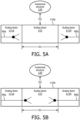
- a dynamic motion scale 110a has three (3) zones of scaling factors 111 and 112.
- Scaling factor 111 applies to a default motion setting of surgical robotic arms 90a and 90b when a tracked distance between surgical robotic arms 90a and 90b is greater than a distance threshold D1 as best shown in FIG. 5A .
- scaling factor 112 applies when a tracked distance between surgical robotic arms 90a and 90b is less than a distance threshold D1 as best shown in FIG. 5B .
- scaling factor 112 may only apply to a default motion setting of surgical robotic arms 90a and 90b when the tracked distance between surgical robotic arms 90a and 90b is less than a distance threshold D1 and further when a tracked distance of surgical robotic 90a and/or surgical robotic arm 90b relative to an anatomical structure 120 is less than a distance threshold D2.
- distance thresholds D1 and D2 may be default thresholds derived from the particular surgical robotic procedure or may be user defined via a graphical user interface.
- scaling factors 111 and 112 may represent any factor associated with the motion of surgical robotic arm 90a including, but not limited to, a positioning, a velocity, an acceleration and a force as previously described herein.
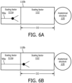
- a dynamic motion scale 110b has two (2) zones of scaling factors 111 and 112.
- Scaling factor 111 applies to a default motion setting of surgical robotic arms 90a and 90b when a tracked distance between surgical robotic arm 90a and anatomical structure 120 is greater than a distance threshold D3 as best shown in FIG. 6A .
- scaling factor 112 applies when a tracked distance between surgical robotic arm 90a and anatomical structure 120 is less than a distance threshold D3 as best shown in FIG. 6B .
- distance threshold D3 may be default thresholds derived from the particular surgical robotic procedure or may be user defined via a graphical user interface.
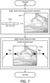
- a flowchart 130 represents an image guided motion scaled robot control of the present disclosure involving an a pre-operative endoscopic view 12a and an intra-operative endoscopic view 12b of a heart.
- a surgical robotic arm holding an endoscope is positioned via a user input device within a surgical coordinate space encircling a cardiac region to acquire pre-operative endoscopic view 12a of the heart. Thereafter, for an intra-operative phase of the surgical robotic procedure, the endoscope is held in or repositioned to the same pre-operative position to acquire an intra-operative endoscopic view 12b of a heart.
- stage S132 of flowchart 130 encompasses a motion scale mapping of a motion scale 110a within an image coordinate space of pre-operative endoscopic view 12a of the heart.
- stage S62 may involve a calibration of the endoscope holding surgical robotic arm and a field of view of the endoscope, and a tracking of the surgical robotic arm within the surgical coordinate space (e.g., an electromagnetic tracking, an optical tracking, a FORS sensor tracking, and encoded joint tracking). From the calibration and tracking, the endoscope holding surgical robotic arm is actuated via a user input device to a desired field of view of the endoscope for the acquisition of pre-operative endoscopic view 12a of the heart.
- a graphical user interface (not shown) is provided for allowing a dynamic delineation of motion scale 110a within an image coordinate space outlining pre-operative endoscopic view 12a of the heart. More particularly, motion scale 110a and an application rule of motion scale 110a are user defined and linked to pre-operative endoscopic view 12a of the heart.
- a stage S134 of flowchart 130 encompasses an actuation of a pair of surgical robotic arms 90a and 90b via a user input device within a 3D surgical coordinate space 13 encircling the cardiac region.
- motion of end-effectors of surgical robotic arms 90a and 90b within surgical coordinate space 13 in accordance with a default motion setting is tracked (e.g., an electromagnetic tracking, an optical tracking, a FORS sensor tracking, and encoded joint tracking).
- motion scale 110 is applied to the default motion setting depending on a tracked distance TD between positons of the end-effectors of surgical robotic arms 90a and 90b within surgical coordinate space 13 or image coordinate space 12b (e.g., an electromagnetic tracking, an optical tracking, a FORS sensor tracking, encoded joint tracking or image tracking).
- a tracked distance TD between positons of the end-effectors of surgical robotic arms 90a and 90b within surgical coordinate space 13 or image coordinate space 12b e.g., an electromagnetic tracking, an optical tracking, a FORS sensor tracking, encoded joint tracking or image tracking.
- FIGS. 8-10 teaches basic inventive principles of an image guided motion scaled surgical robotic system and an image guided motion scaled surgical robotic controller in accordance with the inventive principles of the present disclosure. From this description of FIGS. 8-10 , those having ordinary skill in the art will appreciate how to apply the inventive principles of the present disclosure to practice numerous and various embodiments of an image guided motion scaled surgical robotic system and an image guided motion scaled surgical robotic controller.
- a surgical system of the present disclosure employs an imaging system 140, a tracking system 150 and an image guided motion scaled surgical robotic surgical robotic system 160.
- Imaging system 140 implements any imaging modality, known in the art of the present disclosure and hereinafter conceived, for imaging an anatomical region (not shown) within an image coordinate system 141 and for communicating imaging data IMD IS informative of such imaging to image guided motion scaled surgical robotic surgical robotic system 160.
- imaging modality include, but are not limited to, CT, MRI, X-ray and ultrasound.
- imaging system 140 is an optional component of the surgical system and may be omitted, particularly when image guided motion scaled surgical robotic surgical robotic system 160 employs an imaging instrument held by a surgical robotic arm (not shown) for imaging the anatomical structure within an image coordinate system 161a and generating imaging data IMD II indicative of such imaging.
- imaging instruments include, but are not limited to, an endoscope and a laparoscope.
- Tracking system 150 implements any tracking technique, known in the art of the present disclosure and hereinafter conceived, for tracking a surgical robotic arm within a tracking coordinate system 151 and for communicating tracking data TRD TS indicative of such tracking to image guided motion scaled surgical robotic surgical robotic system 160.
- the tracking technique include, but are not limited to, electromagnetic, optical and FORS sensing.
- tracking system 150 is an optional component of the surgical system and may be omitted, particularly when surgical robotic system 160 employs encoded surgical robots arms (not shown) generating tracking data TRD SRA for tracking the surgical robotic arm(s) within a surgical coordinate space 161b.
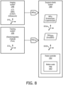
- image guided motion scaled surgical robotic surgical robotic system 160 further employs an image guided motion scaled surgical robotic controller 162 having a motion scale map 163 of the present disclosure for controlling an execution of an imaging guided motion scaled robot control of the present disclosure, such as, for example, the control schemes shown in FIGS. 3 , 4 and 7 .
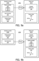
- surgical robotic system 160 may be embodied in numerous and various structural architectures.
- an image guided motion scaled surgical robotic system 160a has an operator console 164a and a robot cart 167a.
- operator console 164a employs robot controller 162 ( FIG. 8 ) of the present disclosure, one or more input devices 165 (e.g., handle(s), joystick(s), roller ball(s), etc.) as known in the art of the present disclosure and a display/image controller 166 as known in the art of the present disclosure.
- robot controller 162 FIG. 8
- input devices 165 e.g., handle(s), joystick(s), roller ball(s), etc.
- display/image controller 166 e.g., liquid crystal display, etc.
- Robot cart 167a employs one or more surgical robotic arms 168 as known in the art of the present disclosure and a patient table 169 as known in the art of the present disclosure, particularly for establishing surgical coordinate space 161b ( FIG. 8 ).
- user input device(s) 165 are manipulated to execute a user defined motion of surgical robotic arm(s) 168 within surgical coordinate space 161b via actuation commands AC SRA communicated by image guided motion scaled robot controller 162 to surgical robotic arm(s) 168.
- image guided motion scaled robot controller 162 will apply motion scale map 163 to an imaging coordinate space (e.g., 161a of FIG. 8 ) registered to surgical robotic space 161b to thereby attenuate or amplify the user defined motion of surgical robotic arm(s) 168 within surgical coordinate space 161b in accordance with the motion scale map 163.
- an image guided motion scaled surgical robotic system 160b has an operator console 164b and a robot cart 167b.
- operator console 164b employs input device(s) 165 (e.g., handles) and a display/image controller 166.
- Robot cart 167b employs surgical robotic arms 168, robot controller 162 ( FIG. 8 ) and patient table 169.
- user input device(s) 165 are manipulated to communicate an input signal IS SRA to image guided motion scaled robot controller 162 with input signal IS SRA being indicative of a user defined motion of surgical robotic arm(s) 168 within surgical coordinate space 161b,
- image guided motion scaled robot controller 162 communicates actuation commands AC SRA (not shown) to surgical robotic arm(s) 168.
- image guided motion scaled robot controller 162 will apply motion scale map 163 to an imaging coordinate space (e.g., 161a of FIG. 8 ) registered to surgical robotic space 161b to thereby attenuate or amplify the user defined motion of surgical robotic arm(s) 168 within surgical coordinate space 161b in accordance with the motion scale map 163.
- image guided motion scaled robot controller 162 may be embodied in numerous and various structural architectures.
- image guided motion scaled robot controller includes a processor, a memory, a user interface, a network interface, and a storage interconnected via one or more system buses.
- the actual organization of the components of image guided motion scaled robot controller 162 may be more complex than illustrated.
- the processor may be any hardware device capable of executing instructions stored in memory or storage or otherwise processing data.
- the processor may include a microprocessor, field programmable gate array (FPGA), application-specific integrated circuit (ASIC), or other similar devices.
- FPGA field programmable gate array
- ASIC application-specific integrated circuit
- the memory may include various memories such as, for example L1, L2, or L3 cache or system memory.
- the memory may include static random access memory (SRAM), dynamic RAM (DRAM), flash memory, read only memory (ROM), or other similar memory devices.
- SRAM static random access memory
- DRAM dynamic RAM
- ROM read only memory
- the user interface may include one or more devices for enabling communication with a user such as an administrator.
- the user interface may include a display, a mouse, and a keyboard for receiving user commands.
- the user interface may include a command line interface or graphical user interface that may be presented to a remote terminal via the network interface.
- the network interface may include one or more devices for enabling communication with other hardware devices.
- the network interface may include a network interface card (NIC) configured to communicate according to the Ethernet protocol.
- NIC network interface card
- the network interface may implement a TCP/IP stack for communication according to the TCP/IP protocols.
- TCP/IP protocols Various alternative or additional hardware or configurations for the network interface will be apparent.
- the storage may include one or more machine-readable storage media such as read-only memory (ROM), random-access memory (RAM), magnetic disk storage media, optical storage media, flash-memory devices, or similar storage media.
- ROM read-only memory
- RAM random-access memory
- magnetic disk storage media such as magnetic disks, optical disks, flash-memory devices, or similar storage media.
- the storage may store instructions for execution by the processor or data upon with the processor may operate.
- the storage may store a base operating system for controlling various basic operations of the hardware.
- the storage may further store application module(s) in the form of executable software/firmware and/or application module(s).
- an image guided motion scaled robot controller 162a may employ application modules including a motion scale mapper 170, a motion vector generator 171a and a surgical robotic arm actuator 172a.
- motion scale mapper 170 processes imaging data IMD IS from imaging system 140 ( FIG. 8 )(if employed) and/or imaging data IMD II from an imaging instrument (if employed)(e.g., an endoscope), and further processes a motion scale delineation signal MSD from a graphical user interface (not shown) to thereby map a motion scale within an image coordinate space as previously described herein.
- Motion scale mapper 170 communicates the motion scale map MSM to motion vector generator 171a, which further processes input signal IS SRA from an input device (e.g., handle(s), joystick(s), roller ball(s), etc.) and tracking data TD TRS from tracking system 150 (if employed)( FIG. 8 ) to thereby generate a motion vector MV indicative of a translation, a rotation and/or a pivoting of a surgical robotic arm 168 with surgical coordinate system 161b as requested by input signal IS SRA and attenuated or amplified in accordance with motion scale map MSM based on tracking data TD TRS .
- an input device e.g., handle(s), joystick(s), roller ball(s), etc.
- tracking data TD TRS from tracking system 150 (if employed)( FIG. 8 )
- motion vector generator 171a may process encoded tracking data TD SRA from surgical robotic arm actuator 172a to thereby generate motion vector MV indicative of a translation, a rotation and/or a pivoting of surgical robotic arm 168 with surgical coordinate system 161b as requested by input signal IS SRA and attenuated or amplified in accordance with motion scale map MSM based on encoded tracking data TD SRA .
- Motion vector generator 171a communicates motion vector MV to surgical robotic arm actuator 172a, which generates actuation commands AC instructive of the translation, rotation and/or pivoting of surgical robotic arm 168 within surgical coordinate system 161b.
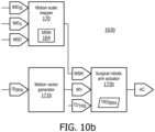
- an image guided motion scaled robot controller 162b may employ application modules including a motion scale mapper 170, a motion vector generator 171b and a surgical robotic arm actuator 172b.
- motion scale mapper 170 processes imaging data IMD IS from imaging system 140 ( FIG. 8 )(if employed) and/or imaging data IMDn from an imaging instrument (if employed)(e.g., an endoscope), and further processes motion scale delineation signal MSD from a graphical user interface (not shown) to thereby map a motion scale within an image coordinate space as previously described herein.
- imaging system 140 FIG. 8
- imaging data IMDn from an imaging instrument (if employed)(e.g., an endoscope)
- motion scale delineation signal MSD from a graphical user interface (not shown) to thereby map a motion scale within an image coordinate space as previously described herein.
- Motion vector generator 171b processes input signal IS SRA from an input device (e.g., handle(s), joystick(s), roller ball(s), etc.) to thereby generate a motion vector MV indicative of a translation, a rotation and/or a pivoting of surgical robotic arm 168 with surgical coordinate system 161b
- an input device e.g., handle(s), joystick(s), roller ball(s), etc.
- Motion scale mapper 170 communicates the motion scale map MSM to surgical robotic arm actuator 172b and motion vector generator 171b communicates the motion vector MV to surgical robotic arm actuator 172b, which further processes tracking data TD TRS from tracking system 150 (if employed)( FIG. 8 ) to thereby generate actuation commands AC indicative of a translation, a rotation and/or a pivoting of surgical robotic arm 168 with surgical coordinate system 161b as requested by input signal IS SRA and attenuated or amplified in accordance with motion scale map MSM based on tracking data TD TRS .
- surgical robotic arm actuator 172b may process encoded tracking data TD SRA to thereby generate actuation commands AC indicative of a translation, a rotation and/or a pivoting of surgical robotic arm 168 with surgical coordinate system 161b as requested by input signal IS SRA and attenuated or amplified in accordance with motion scale map MSM based on encoded tracking data TD SRA .
- features, elements, components, etc. described in the present disclosure/specification and/or depicted in the Figures may be implemented in various combinations of electronic components/circuitry, hardware, executable software and executable firmware and provide functions which may be combined in a single element or multiple elements.
- the functions of the various features, elements, components, etc. shown/illustrated/depicted in the Figures can be provided through the use of dedicated hardware as well as hardware capable of executing software in association with appropriate software.
- the functions can be provided by a single dedicated processor, by a single shared processor, or by a plurality of individual processors, some of which can be shared and/or multiplexed.
- processor should not be construed to refer exclusively to hardware capable of executing software, and can implicitly include, without limitation, digital signal processor (“DSP”) hardware, memory (e.g., read only memory (“ROM”) for storing software, random access memory (“RAM”), non-volatile storage, etc.) and virtually any means and/or machine (including hardware, software, firmware, circuitry, combinations thereof, etc.) which is capable of (and/or configurable) to perform and/or control a process.
- DSP digital signal processor
- ROM read only memory
- RAM random access memory
- non-volatile storage etc.
- machine including hardware, software, firmware, circuitry, combinations thereof, etc.
- any flow charts, flow diagrams and the like can represent various processes which can be substantially represented in computer readable storage media and so executed by a computer, processor or other device with processing capabilities, whether or not such computer or processor is explicitly shown.
- exemplary embodiments of the present disclosure can take the form of a computer program product or application module accessible from a computer-usable and/or computer-readable storage medium providing program code and/or instructions for use by or in connection with, e.g., a computer or any instruction execution system.
- a computer-usable or computer readable storage medium can be any apparatus that can, e.g., include, store, communicate, propagate or transport the program for use by or in connection with the instruction execution system, apparatus or device.
- Such exemplary medium can be, e.g., an electronic, magnetic, optical, electromagnetic, infrared or semiconductor system (or apparatus or device) or a propagation medium.
- Examples of a computer-readable medium include, e.g., a semiconductor or solid state memory, magnetic tape, a removable computer diskette, a random access memory (RAM), a read-only memory (ROM), flash (drive), a rigid magnetic disk and an optical disk.
- Current examples of optical disks include compact disk - read only memory (CD-ROM), compact disk - read/write (CD-R/W) and DVD.
Landscapes
- Health & Medical Sciences (AREA)
- Engineering & Computer Science (AREA)
- Surgery (AREA)
- Life Sciences & Earth Sciences (AREA)
- Robotics (AREA)
- Heart & Thoracic Surgery (AREA)
- Nuclear Medicine, Radiotherapy & Molecular Imaging (AREA)
- Biomedical Technology (AREA)
- Medical Informatics (AREA)
- Molecular Biology (AREA)
- Animal Behavior & Ethology (AREA)
- General Health & Medical Sciences (AREA)
- Public Health (AREA)
- Veterinary Medicine (AREA)
- Mechanical Engineering (AREA)
- Manipulator (AREA)
- Endoscopes (AREA)
Claims (14)
- Bildgeführtes, bewegungsskaliertes chirurgisches Robotersystem (160), umfassend:einen chirurgischen Roboterarm (168); undeine bildgeführte, bewegungsskalierte Robotersteuereinheit (162), die mit dem chirurgischen Roboterarm (168) in Verbindung steht,wobei die bildgeführte, bewegungsskalierte Robotersteuereinheit (162) strukturell so konfiguriert ist, dass sie als Reaktion auf ein Eingangssignal, das eine benutzerdefinierte Bewegung des chirurgischen Roboterarms (168) innerhalb eines anatomischen Bereichs anzeigt, eine betätigte Bewegung des chirurgischen Roboterarms (168) innerhalb des anatomischen Bereichs auf der Grundlage eines Parameters steuert, der sich auf die Bewegung des chirurgischen Roboterarms relativ zu einer Karte (164) einer Bewegungsskala bezieht, die innerhalb einer Abbildung des anatomischen Bereichs und des Signals abgegrenzt ist;wobei die Karte (164) einer Bewegungsskala mindestens einen Skalierungsfaktor beinhaltet.
- Bildgeführtes, bewegungsskaliertes chirurgisches Robotersystem (160) nach Anspruch 1,
wobei die bildgeführte, bewegungsskalierte Robotersteuereinheit (162) weiter strukturell so konfiguriert ist, dass sie eine Abgrenzung der Bewegungsskala innerhalb der Abbildung des anatomischen Bereichs steuert. - Bildgeführtes, bewegungsskaliertes chirurgisches Robotersystem (160) nach Anspruch 1,
wobei die bildgeführte, bewegungsskalierte Robotersteuereinheit (162) weiter strukturell so konfiguriert ist, dass sie eine Abgrenzung der Bewegungsskala in Abhängigkeit von einem Abstand zwischen dem chirurgischen Roboterarm (168) und einer anatomischen Struktur innerhalb der Abbildung des anatomischen Bereichs steuert. - Bildgeführtes, bewegungsskaliertes chirurgisches Robotersystem (160) nach Anspruch 1, weiter umfassend:einen zusätzlichen chirurgischen Roboterarm (168); undwobei die bildgeführte, bewegungsskalierte Robotersteuereinheit (162) weiter strukturell so konfiguriert ist, dass sie eine Abgrenzung der Bewegungsskala in Abhängigkeit von einem Abstand zwischen dem chirurgischen Roboterarm (168) und dem zusätzlichen chirurgischen Roboterarm (168) relativ zu einer anatomischen Struktur innerhalb der Abbildung des anatomischen Bereichs steuert.
- Bildgeführtes, bewegungsskaliertes chirurgisches Robotersystem (160) nach Anspruch 1,
wobei die bildgeführte, bewegungsskalierte Robotersteuereinheit (162) weiter strukturell so konfiguriert ist, dass sie die betätigte Bewegung des chirurgischen Roboterarms (168) innerhalb des anatomischen Bereichs als Reaktion auf Verfolgungsdaten steuert, die eine Verfolgung des chirurgischen Roboterarms (168) innerhalb des anatomischen Bereichs anzeigen. - Bildgeführtes, bewegungsskaliertes chirurgisches Robotersystem (160) nach Anspruch 1,
wobei die bildgeführte, bewegungsskalierte Robotersteuereinheit (162) weiter strukturell so konfiguriert ist, dass sie die betätigte Bewegung des chirurgischen Roboterarms (168) innerhalb des anatomischen Bereichs als Reaktion auf Verfolgungsdaten steuert, die eine Verfolgung des chirurgischen Roboterarms (168) innerhalb der Abbildung des anatomischen Bereichs anzeigen. - Bildgeführtes, bewegungsskaliertes chirurgisches Robotersystem (160) nach Anspruch 1, wobei die Bewegungsskala eine von einer Positionsbewegungsskala, einer Geschwindigkeitsbewegungsskala, einer Beschleunigungsbewegungsskala und einer Kraftbewegungsskala ist.
- Bildgeführte, bewegungsskalierte Robotersteuereinheit (162), umfassend:einen Bewegungsvektorgenerator (171), der strukturell so konfiguriert ist, dass er ein Bewegungsvektorsignal als Reaktion auf ein Eingangssignal erzeugt, das eine benutzerdefinierte Bewegung eines chirurgischen Roboterarms (168) innerhalb eines anatomischen Bereichs anzeigt,
wobei das Bewegungsvektorsignal eine betätigte Bewegung eines chirurgischen Roboterarms (168) innerhalb des anatomischen Bereichs anzeigt;eine Betätigungsvorrichtung (172) für einen chirurgischen Roboterarm, die strukturell so konfiguriert ist, dass sie Betätigungsbefehle als Reaktion auf eine Erzeugung des Bewegungsvektorsignals durch den Bewegungsvektorgenerator (171) erzeugt,
wobei die Betätigungsbefehle die betätigte Bewegung des chirurgischen Roboterarms (168) innerhalb des anatomischen Bereichs anweisen; undwobei eines der Folgenden gilt:der Bewegungsvektorgenerator (171) ist weiter strukturell so konfiguriert, dass er das Bewegungsvektorsignal auf der Grundlage eines Parameters erzeugt, der sich auf die Bewegung des chirurgischen Roboterarms relativ zu einer Karte (164) einer Bewegungsskala bezieht, die innerhalb einer Abbildung des anatomischen Bereichs abgegrenzt ist; unddie Betätigungsvorrichtung (172) für den chirurgischen Roboterarm ist weiter strukturell so konfiguriert, dass sie die Betätigungsbefehle auf der Grundlage eines Parameters erzeugt, der sich auf die Bewegung des chirurgischen Roboterarms relativ zu der Bewegungsskala bezieht, die innerhalb einer Abbildung des anatomischen Bereichs abgegrenzt ist;wobei die Bewegungsskala mindestens einen Skalierungsfaktor beinhaltet. - Bildgeführte, bewegungsskalierte chirurgische Robotersteuereinheit (162) nach Anspruch 8, weiter umfassend:einen Bewegungsskalenabbilder (170), der strukturell so konfiguriert ist, dass er die Bewegungsskala innerhalb des Bildkoordinatenraums abgrenzt, odereinen Bewegungsskalenabbilder (170), der strukturell so konfiguriert ist, dass er die Bewegungsskala in Abhängigkeit von einem Abstand zwischen dem chirurgischen Roboterarm (168) und einer anatomischen Struktur innerhalb des Bildkoordinatenraums berechnet.
- Bildgeführte, bewegungsskalierte chirurgische Robotersteuereinheit (162) nach Anspruch 8, weiter umfassend:
einen Bewegungsskalenabbilder (170), der strukturell so konfiguriert ist, dass er die Bewegungsskala in Abhängigkeit von einem Abstand zwischen dem chirurgischen Roboterarm (168) und dem zusätzlichen chirurgischen Roboterarm (168) relativ zu einer anatomischen Struktur innerhalb des Bildkoordinatenraums berechnet. - Bildgeführte, bewegungsskalierte chirurgische Robotersteuereinheit (162) nach Anspruch 8,
wobei eines der Folgenden gilt:der Bewegungsvektorgenerator (171) ist weiter strukturell so konfiguriert, dass er das Bewegungsvektorsignal als Reaktion auf Verfolgungsdaten erzeugt, die eine Verfolgung des chirurgischen Roboterarms (168) innerhalb des chirurgischen Koordinatenraums anzeigen; unddie Betätigungsvorrichtung (172) des chirurgischen Roboterarms (168) ist weiter strukturell so konfiguriert, dass sie die Betätigungsbefehle als Reaktion auf die Verfolgungsdaten erzeugt, die die Verfolgung des chirurgischen Roboterarms (168) innerhalb des chirurgischen Koordinatenraums anzeigen. - Bildgeführte, bewegungsskalierte chirurgische Robotersteuereinheit (162) nach Anspruch 8,
wobei eines der Folgenden gilt:der Bewegungsvektorgenerator (171) ist weiter strukturell so konfiguriert, dass er das Bewegungsvektorsignal als Reaktion auf Verfolgungsdaten erzeugt, die eine Verfolgung des chirurgischen Roboterarms (168) innerhalb des Bildkoordinatenraums anzeigen; unddie Betätigungsvorrichtung (172) des chirurgischen Roboterarms (168) ist weiter strukturell so konfiguriert, dass sie die Betätigungsbefehle als Reaktion auf Verfolgungsdaten erzeugt, die die Verfolgung innerhalb des Bildkoordinatenraums anzeigen. - Bildgeführte, bewegungsskalierte chirurgische Robotersteuereinheit (162) nach Anspruch 8, wobei die Bewegungsskala eine von einer Positionsbewegungsskala, einer Geschwindigkeitsbewegungsskala, einer Beschleunigungsbewegungsskala und einer Kraftbewegungsskala ist.
- Computerprogrammprodukt, das Anweisungen umfasst, die, wenn sie auf einem Prozessor ausgeführt werden, den Prozessor veranlassen, ein Verfahren zur bildgeführten bewegungsskalierten Steuerung eines chirurgischen Roboters für ein bildgeführtes bewegungsskaliertes Robotersystem (160) durchzuführen, das einen chirurgischen Roboterarm (168) und eine bildgeführte bewegungsskalierte Robotersteuereinheit (162) beinhaltet, wobei das Verfahren zur bildgeführten bewegungsskalierten Steuerung eines chirurgischen Roboters Folgendes umfasst:Empfangen eines Eingangssignals, das eine benutzerdefinierte Bewegung des chirurgischen Roboterarms (168) in einem anatomischen Bereich anzeigt, durch die bildgeführte, bewegungsskalierte Robotersteuereinheit (162); undSteuern einer betätigten Bewegung des chirurgischen Roboterarms (168) innerhalb des anatomischen Bereichs durch die bildgeführte bewegungsskalierte Robotersteuereinheit (162) als Reaktion auf das Eingangssignal auf der Grundlage eines Parameters, der sich auf die Bewegung des chirurgischen Roboterarms relativ zu einer Karte (164) einer Bewegungsskala bezieht, die innerhalb einer Abbildung des anatomischen Bereichs und des Signals abgegrenzt ist;wobei die Karte (164) einer Bewegungsskala mindestens einen Skalierungsfaktor beinhaltet.
Applications Claiming Priority (2)
| Application Number | Priority Date | Filing Date | Title |
|---|---|---|---|
| US201662430994P | 2016-12-07 | 2016-12-07 | |
| PCT/EP2017/081423 WO2018104252A1 (en) | 2016-12-07 | 2017-12-05 | Image guided motion scaling for robot control |
Publications (2)
| Publication Number | Publication Date |
|---|---|
| EP3551117A1 EP3551117A1 (de) | 2019-10-16 |
| EP3551117B1 true EP3551117B1 (de) | 2024-06-05 |
Family
ID=60954988
Family Applications (1)
| Application Number | Title | Priority Date | Filing Date |
|---|---|---|---|
| EP17828659.7A Active EP3551117B1 (de) | 2016-12-07 | 2017-12-05 | Bildgeführte bewegungsskalierung für eine robotersteuerung |
Country Status (5)
| Country | Link |
|---|---|
| US (2) | US11213364B2 (de) |
| EP (1) | EP3551117B1 (de) |
| JP (1) | JP7132922B2 (de) |
| CN (1) | CN110049742B (de) |
| WO (1) | WO2018104252A1 (de) |
Families Citing this family (38)
| Publication number | Priority date | Publication date | Assignee | Title |
|---|---|---|---|---|
| JP7746073B2 (ja) * | 2021-08-31 | 2025-09-30 | 川崎重工業株式会社 | 手術支援システムおよび手術支援システムの制御方法 |
| ITUB20155057A1 (it) | 2015-10-16 | 2017-04-16 | Medical Microinstruments S R L | Assieme robotico di chirurgia |
| US11583358B2 (en) * | 2017-09-06 | 2023-02-21 | Covidien Lp | Boundary scaling of surgical robots |
| US11304692B2 (en) | 2018-07-16 | 2022-04-19 | Cilag Gmbh International | Singular EMR source emitter assembly |
| US11992282B2 (en) | 2019-03-15 | 2024-05-28 | Cilag Gmbh International | Motion capture controls for robotic surgery |
| US11284957B2 (en) | 2019-03-15 | 2022-03-29 | Cilag Gmbh International | Robotic surgical controls with force feedback |
| US11471229B2 (en) | 2019-03-15 | 2022-10-18 | Cilag Gmbh International | Robotic surgical systems with selectively lockable end effectors |
| US11701190B2 (en) | 2019-03-15 | 2023-07-18 | Cilag Gmbh International | Selectable variable response of shaft motion of surgical robotic systems |
| US11490981B2 (en) | 2019-03-15 | 2022-11-08 | Cilag Gmbh International | Robotic surgical controls having feedback capabilities |
| US11583350B2 (en) | 2019-03-15 | 2023-02-21 | Cilag Gmbh International | Jaw coordination of robotic surgical controls |
| US11690690B2 (en) | 2019-03-15 | 2023-07-04 | Cilag Gmbh International | Segmented control inputs for surgical robotic systems |
| US11666401B2 (en) | 2019-03-15 | 2023-06-06 | Cilag Gmbh International | Input controls for robotic surgery |
| US12257013B2 (en) * | 2019-03-15 | 2025-03-25 | Cilag Gmbh International | Robotic surgical systems with mechanisms for scaling camera magnification according to proximity of surgical tool to tissue |
| JP2020163522A (ja) * | 2019-03-29 | 2020-10-08 | ソニー株式会社 | 制御装置及びマスタスレーブシステム |
| US11776144B2 (en) | 2019-12-30 | 2023-10-03 | Cilag Gmbh International | System and method for determining, adjusting, and managing resection margin about a subject tissue |
| US11284963B2 (en) | 2019-12-30 | 2022-03-29 | Cilag Gmbh International | Method of using imaging devices in surgery |
| US11219501B2 (en) | 2019-12-30 | 2022-01-11 | Cilag Gmbh International | Visualization systems using structured light |
| US11744667B2 (en) | 2019-12-30 | 2023-09-05 | Cilag Gmbh International | Adaptive visualization by a surgical system |
| US12207881B2 (en) | 2019-12-30 | 2025-01-28 | Cilag Gmbh International | Surgical systems correlating visualization data and powered surgical instrument data |
| US12002571B2 (en) | 2019-12-30 | 2024-06-04 | Cilag Gmbh International | Dynamic surgical visualization systems |
| US11832996B2 (en) | 2019-12-30 | 2023-12-05 | Cilag Gmbh International | Analyzing surgical trends by a surgical system |
| US11648060B2 (en) | 2019-12-30 | 2023-05-16 | Cilag Gmbh International | Surgical system for overlaying surgical instrument data onto a virtual three dimensional construct of an organ |
| US11896442B2 (en) | 2019-12-30 | 2024-02-13 | Cilag Gmbh International | Surgical systems for proposing and corroborating organ portion removals |
| US12453592B2 (en) | 2019-12-30 | 2025-10-28 | Cilag Gmbh International | Adaptive surgical system control according to surgical smoke cloud characteristics |
| US12053223B2 (en) | 2019-12-30 | 2024-08-06 | Cilag Gmbh International | Adaptive surgical system control according to surgical smoke particulate characteristics |
| US11759283B2 (en) | 2019-12-30 | 2023-09-19 | Cilag Gmbh International | Surgical systems for generating three dimensional constructs of anatomical organs and coupling identified anatomical structures thereto |
| CN112155613B (zh) * | 2020-09-14 | 2021-10-22 | 武汉联影智融医疗科技有限公司 | 一种微创医疗手术设备 |
| US12070287B2 (en) | 2020-12-30 | 2024-08-27 | Cilag Gmbh International | Robotic surgical tools having dual articulation drives |
| US12059170B2 (en) | 2020-12-30 | 2024-08-13 | Cilag Gmbh International | Surgical tool with tool-based translation and lock for the same |
| US12239404B2 (en) | 2020-12-30 | 2025-03-04 | Cilag Gmbh International | Torque-based transition between operating gears |
| US11813746B2 (en) | 2020-12-30 | 2023-11-14 | Cilag Gmbh International | Dual driving pinion crosscheck |
| IT202100016154A1 (it) | 2021-06-21 | 2022-12-21 | Medical Microinstruments Inc | Strumento chirurgico per chirurgia robotica |
| JP7716276B2 (ja) * | 2021-08-31 | 2025-07-31 | 川崎重工業株式会社 | 手術支援システムおよび手術支援システムの制御方法 |
| US20250345940A1 (en) * | 2022-01-14 | 2025-11-13 | Ntt Docomo, Inc. | Human augmentation platform device and physical ability augmentation method |
| IT202200006332A1 (it) * | 2022-03-31 | 2023-10-01 | Medical Microinstruments Inc | Metodo per controllare, tramite diminuzione di velocità o potenza impartita, un dispositivo slave comandato da un dispositivo master in un sistema robotico per teleoperazione medica o chirurgica, e relativo sistema robotico |
| IT202200006338A1 (it) * | 2022-03-31 | 2023-10-01 | Medical Microinstruments Inc | Metodo per controllare un dispositivo slave, comandato da un dispositivo master movimentabile da un operatore in un sistema robotico per teleoperazione medica o chirurgica, in prossimità di limiti di movimento del dispositivo slave, e relativo sistema robotico |
| US12137904B2 (en) | 2022-06-15 | 2024-11-12 | Cilag Gmbh International | Impact mechanism for grasp clamp fire |
| GB2625105B (en) * | 2022-12-06 | 2025-05-28 | Cmr Surgical Ltd | Control system for a surgical robotic system |
Family Cites Families (37)
| Publication number | Priority date | Publication date | Assignee | Title |
|---|---|---|---|---|
| US5382885A (en) | 1993-08-09 | 1995-01-17 | The University Of British Columbia | Motion scaling tele-operating system with force feedback suitable for microsurgery |
| US5855583A (en) | 1996-02-20 | 1999-01-05 | Computer Motion, Inc. | Method and apparatus for performing minimally invasive cardiac procedures |
| US6468265B1 (en) * | 1998-11-20 | 2002-10-22 | Intuitive Surgical, Inc. | Performing cardiac surgery without cardioplegia |
| US6522906B1 (en) * | 1998-12-08 | 2003-02-18 | Intuitive Surgical, Inc. | Devices and methods for presenting and regulating auxiliary information on an image display of a telesurgical system to assist an operator in performing a surgical procedure |
| US8944070B2 (en) * | 1999-04-07 | 2015-02-03 | Intuitive Surgical Operations, Inc. | Non-force reflecting method for providing tool force information to a user of a telesurgical system |
| US6424885B1 (en) * | 1999-04-07 | 2002-07-23 | Intuitive Surgical, Inc. | Camera referenced control in a minimally invasive surgical apparatus |
| US20190090967A1 (en) * | 1999-12-14 | 2019-03-28 | Intuitive Surgical Operations, Inc. | Display of computer generated image of an out-of-view portion of a medical device adjacent a real-time image of an in-view portion of the medical device |
| US7198630B2 (en) * | 2002-12-17 | 2007-04-03 | Kenneth I. Lipow | Method and apparatus for controlling a surgical robot to mimic, harmonize and enhance the natural neurophysiological behavior of a surgeon |
| US8010180B2 (en) * | 2002-03-06 | 2011-08-30 | Mako Surgical Corp. | Haptic guidance system and method |
| US9867669B2 (en) * | 2008-12-31 | 2018-01-16 | Intuitive Surgical Operations, Inc. | Configuration marker design and detection for instrument tracking |
| US8398541B2 (en) * | 2006-06-06 | 2013-03-19 | Intuitive Surgical Operations, Inc. | Interactive user interfaces for robotic minimally invasive surgical systems |
| US8079950B2 (en) | 2005-09-29 | 2011-12-20 | Intuitive Surgical Operations, Inc. | Autofocus and/or autoscaling in telesurgery |
| EP2139422B1 (de) * | 2007-03-26 | 2016-10-26 | Hansen Medical, Inc. | Robotische kathetersysteme und verfahren |
| US8620473B2 (en) * | 2007-06-13 | 2013-12-31 | Intuitive Surgical Operations, Inc. | Medical robotic system with coupled control modes |
| KR20100120183A (ko) * | 2008-01-30 | 2010-11-12 | 더 트러스티이스 오브 콜롬비아 유니버시티 인 더 시티 오브 뉴욕 | 로봇을 이용한 미세수술 스텐트 시술을 위한 시스템, 디바이스 및 방법 |
| US8155479B2 (en) * | 2008-03-28 | 2012-04-10 | Intuitive Surgical Operations Inc. | Automated panning and digital zooming for robotic surgical systems |
| CN104605928B (zh) * | 2009-05-08 | 2018-01-05 | 圣犹达医疗用品国际控股有限公司 | 用于在基于导管的消融治疗中控制损伤尺寸的系统 |
| EP2542296A4 (de) * | 2010-03-31 | 2014-11-26 | St Jude Medical Atrial Fibrill | Intuitive benutzeroberflächensteuerung zur fernnavigation eines katheters sowie 3d-kartierungs- und visualisierungssysteme |
| WO2012035492A1 (en) | 2010-09-15 | 2012-03-22 | Koninklijke Philips Electronics N.V. | Robotic control of an endoscope from blood vessel tree images |
| KR20120068597A (ko) * | 2010-12-17 | 2012-06-27 | 주식회사 이턴 | 수술 로봇 시스템 및 적응 제어 방법 |
| US8918215B2 (en) * | 2011-01-19 | 2014-12-23 | Harris Corporation | Telematic interface with control signal scaling based on force sensor feedback |
| KR101802464B1 (ko) | 2011-08-03 | 2017-11-28 | 주식회사 미래컴퍼니 | 수술용 로봇의 마스터 암 구조 및 수술용 마스터 로봇의 제어방법 |
| JP5841451B2 (ja) | 2011-08-04 | 2016-01-13 | オリンパス株式会社 | 手術器具およびその制御方法 |
| EP2793680A2 (de) | 2011-12-21 | 2014-10-29 | Koninklijke Philips N.V. | Überlagerungs- und bewegungskompensation von strukturen aus volumetrischen modalitäten auf video eines unkalibrierten endoskops |
| US8880223B2 (en) * | 2012-07-16 | 2014-11-04 | Florida Institute for Human & Maching Cognition | Anthro-centric multisensory interface for sensory augmentation of telesurgery |
| ES2804681T3 (es) | 2013-02-04 | 2021-02-09 | Childrens Nat Medical Ct | Sistema robótico quirúrgico de control híbrido |
| WO2014181222A1 (en) * | 2013-05-09 | 2014-11-13 | Koninklijke Philips N.V. | Robotic control of an endoscope from anatomical features |
| AU2015259635B2 (en) * | 2014-05-15 | 2019-04-18 | Covidien Lp | Systems and methods for controlling a camera position in a surgical robotic system |
| EP4233769A3 (de) * | 2014-08-22 | 2023-11-08 | Intuitive Surgical Operations, Inc. | Systeme und verfahren für adaptive eingabeabbildung |
| CN106714722A (zh) | 2014-09-29 | 2017-05-24 | 柯惠Lp公司 | 用于控制机器人手术系统的动态输入缩放 |
| US10154239B2 (en) * | 2014-12-30 | 2018-12-11 | Onpoint Medical, Inc. | Image-guided surgery with surface reconstruction and augmented reality visualization |
| CN107249498B (zh) | 2015-02-19 | 2024-04-23 | 柯惠Lp公司 | 机器人手术系统的输入装置的重定位方法 |
| CN104622585B (zh) * | 2015-03-13 | 2016-07-20 | 中国科学院重庆绿色智能技术研究院 | 一种腹腔镜微创手术机器人主从同构式遥操作主手 |
| US20160314717A1 (en) * | 2015-04-27 | 2016-10-27 | KindHeart, Inc. | Telerobotic surgery system for remote surgeon training using robotic surgery station coupled to remote surgeon trainee and instructor stations and associated methods |
| EP3361979A4 (de) * | 2015-10-14 | 2019-06-26 | Surgical Theater LLC | Chirurgische navigation mit erweiterter realität |
| ITUB20155057A1 (it) * | 2015-10-16 | 2017-04-16 | Medical Microinstruments S R L | Assieme robotico di chirurgia |
| US12390287B2 (en) * | 2015-10-16 | 2025-08-19 | Medical Microinstruments, Inc. | Surgical tool for robotic surgery and robotic surgical assembly |
-
2017
- 2017-12-05 WO PCT/EP2017/081423 patent/WO2018104252A1/en not_active Ceased
- 2017-12-05 EP EP17828659.7A patent/EP3551117B1/de active Active
- 2017-12-05 JP JP2019530072A patent/JP7132922B2/ja active Active
- 2017-12-05 US US16/467,080 patent/US11213364B2/en active Active
- 2017-12-05 CN CN201780075882.XA patent/CN110049742B/zh active Active
-
2021
- 2021-12-11 US US17/548,507 patent/US12171520B2/en active Active
Also Published As
| Publication number | Publication date |
|---|---|
| JP7132922B2 (ja) | 2022-09-07 |
| US11213364B2 (en) | 2022-01-04 |
| US12171520B2 (en) | 2024-12-24 |
| EP3551117A1 (de) | 2019-10-16 |
| CN110049742B (zh) | 2023-01-03 |
| JP2020500620A (ja) | 2020-01-16 |
| US20220096189A1 (en) | 2022-03-31 |
| WO2018104252A1 (en) | 2018-06-14 |
| US20190307524A1 (en) | 2019-10-10 |
| CN110049742A (zh) | 2019-07-23 |
Similar Documents
| Publication | Publication Date | Title |
|---|---|---|
| EP3551117B1 (de) | Bildgeführte bewegungsskalierung für eine robotersteuerung | |
| JP7233841B2 (ja) | ロボット外科手術システムのロボットナビゲーション | |
| US12396811B2 (en) | Automatic motion control of a dependent surgical robotic arm | |
| EP3375400B1 (de) | Robotische navigation von robotischen chirurgischen systemen | |
| Nagy et al. | A dvrk-based framework for surgical subtask automation | |
| US8560118B2 (en) | Methods, devices, and systems for non-mechanically restricting and/or programming movement of a tool of a manipulator along a single axis | |
| EP2931159B1 (de) | Registrierung und navigation mittels eines sensors für dreidimensionale verfolgung | |
| JP7094727B2 (ja) | カテーテルアブレーション治療中の視野角の自動追跡及び調節 | |
| EP4326182A2 (de) | Roboterchirurgie | |
| WO2009037576A2 (en) | Methods, devices, and systems for non-mechanically restricting and/or programming movement of a tool of a manipulator along a single axis | |
| JP2020512116A (ja) | マーカーレスロボット追跡システム、制御装置、及び方法 | |
| Caborni et al. | Risk-based path planning for a steerable flexible probe for neurosurgical intervention | |
| EP4196036B1 (de) | Bestimmung eines vermeidungsbereichs für eine referenzvorrichtung | |
| JP2026500177A (ja) | 生体構造セグメンテーション及び解剖学的構造追跡のためのシステム及び方法 | |
| HK1261433A1 (en) | Robotic navigation of robotic surgical systems | |
| HK1261433B (en) | Robotic navigation of robotic surgical systems | |
| HK1257573A1 (en) | Robotic navigation of robotic surgical systems |
Legal Events
| Date | Code | Title | Description |
|---|---|---|---|
| STAA | Information on the status of an ep patent application or granted ep patent |
Free format text: STATUS: UNKNOWN |
|
| STAA | Information on the status of an ep patent application or granted ep patent |
Free format text: STATUS: THE INTERNATIONAL PUBLICATION HAS BEEN MADE |
|
| PUAI | Public reference made under article 153(3) epc to a published international application that has entered the european phase |
Free format text: ORIGINAL CODE: 0009012 |
|
| STAA | Information on the status of an ep patent application or granted ep patent |
Free format text: STATUS: REQUEST FOR EXAMINATION WAS MADE |
|
| 17P | Request for examination filed |
Effective date: 20190708 |
|
| AK | Designated contracting states |
Kind code of ref document: A1 Designated state(s): AL AT BE BG CH CY CZ DE DK EE ES FI FR GB GR HR HU IE IS IT LI LT LU LV MC MK MT NL NO PL PT RO RS SE SI SK SM TR |
|
| AX | Request for extension of the european patent |
Extension state: BA ME |
|
| DAV | Request for validation of the european patent (deleted) | ||
| DAX | Request for extension of the european patent (deleted) | ||
| RAP1 | Party data changed (applicant data changed or rights of an application transferred) |
Owner name: KONINKLIJKE PHILIPS N.V. |
|
| REG | Reference to a national code |
Ref country code: DE Ref legal event code: R079 Free format text: PREVIOUS MAIN CLASS: A61B0034300000 Ipc: A61B0034370000 Ref document number: 602017082440 Country of ref document: DE |
|
| GRAP | Despatch of communication of intention to grant a patent |
Free format text: ORIGINAL CODE: EPIDOSNIGR1 |
|
| STAA | Information on the status of an ep patent application or granted ep patent |
Free format text: STATUS: GRANT OF PATENT IS INTENDED |
|
| RIC1 | Information provided on ipc code assigned before grant |
Ipc: A61B 34/00 20160101ALI20230913BHEP Ipc: A61B 34/37 20160101AFI20230913BHEP |
|
| INTG | Intention to grant announced |
Effective date: 20231009 |
|
| GRAJ | Information related to disapproval of communication of intention to grant by the applicant or resumption of examination proceedings by the epo deleted |
Free format text: ORIGINAL CODE: EPIDOSDIGR1 |
|
| STAA | Information on the status of an ep patent application or granted ep patent |
Free format text: STATUS: REQUEST FOR EXAMINATION WAS MADE |
|
| INTC | Intention to grant announced (deleted) | ||
| GRAP | Despatch of communication of intention to grant a patent |
Free format text: ORIGINAL CODE: EPIDOSNIGR1 |
|
| STAA | Information on the status of an ep patent application or granted ep patent |
Free format text: STATUS: GRANT OF PATENT IS INTENDED |
|
| INTG | Intention to grant announced |
Effective date: 20240108 |
|
| GRAS | Grant fee paid |
Free format text: ORIGINAL CODE: EPIDOSNIGR3 |
|
| GRAA | (expected) grant |
Free format text: ORIGINAL CODE: 0009210 |
|
| STAA | Information on the status of an ep patent application or granted ep patent |
Free format text: STATUS: THE PATENT HAS BEEN GRANTED |
|
| AK | Designated contracting states |
Kind code of ref document: B1 Designated state(s): AL AT BE BG CH CY CZ DE DK EE ES FI FR GB GR HR HU IE IS IT LI LT LU LV MC MK MT NL NO PL PT RO RS SE SI SK SM TR |
|
| REG | Reference to a national code |
Ref country code: GB Ref legal event code: FG4D |
|
| REG | Reference to a national code |
Ref country code: CH Ref legal event code: EP |
|
| REG | Reference to a national code |
Ref country code: DE Ref legal event code: R096 Ref document number: 602017082440 Country of ref document: DE |
|
| REG | Reference to a national code |
Ref country code: IE Ref legal event code: FG4D |
|
| REG | Reference to a national code |
Ref country code: LT Ref legal event code: MG9D |
|
| PG25 | Lapsed in a contracting state [announced via postgrant information from national office to epo] |
Ref country code: BG Free format text: LAPSE BECAUSE OF FAILURE TO SUBMIT A TRANSLATION OF THE DESCRIPTION OR TO PAY THE FEE WITHIN THE PRESCRIBED TIME-LIMIT Effective date: 20240605 |
|
| REG | Reference to a national code |
Ref country code: NL Ref legal event code: MP Effective date: 20240605 |
|
| PG25 | Lapsed in a contracting state [announced via postgrant information from national office to epo] |
Ref country code: FI Free format text: LAPSE BECAUSE OF FAILURE TO SUBMIT A TRANSLATION OF THE DESCRIPTION OR TO PAY THE FEE WITHIN THE PRESCRIBED TIME-LIMIT Effective date: 20240605 Ref country code: HR Free format text: LAPSE BECAUSE OF FAILURE TO SUBMIT A TRANSLATION OF THE DESCRIPTION OR TO PAY THE FEE WITHIN THE PRESCRIBED TIME-LIMIT Effective date: 20240605 |
|
| PG25 | Lapsed in a contracting state [announced via postgrant information from national office to epo] |
Ref country code: GR Free format text: LAPSE BECAUSE OF FAILURE TO SUBMIT A TRANSLATION OF THE DESCRIPTION OR TO PAY THE FEE WITHIN THE PRESCRIBED TIME-LIMIT Effective date: 20240906 |
|
| PG25 | Lapsed in a contracting state [announced via postgrant information from national office to epo] |
Ref country code: ES Free format text: LAPSE BECAUSE OF FAILURE TO SUBMIT A TRANSLATION OF THE DESCRIPTION OR TO PAY THE FEE WITHIN THE PRESCRIBED TIME-LIMIT Effective date: 20240605 |
|
| PG25 | Lapsed in a contracting state [announced via postgrant information from national office to epo] |
Ref country code: LV Free format text: LAPSE BECAUSE OF FAILURE TO SUBMIT A TRANSLATION OF THE DESCRIPTION OR TO PAY THE FEE WITHIN THE PRESCRIBED TIME-LIMIT Effective date: 20240605 |
|
| PG25 | Lapsed in a contracting state [announced via postgrant information from national office to epo] |
Ref country code: NO Free format text: LAPSE BECAUSE OF FAILURE TO SUBMIT A TRANSLATION OF THE DESCRIPTION OR TO PAY THE FEE WITHIN THE PRESCRIBED TIME-LIMIT Effective date: 20240905 Ref country code: LV Free format text: LAPSE BECAUSE OF FAILURE TO SUBMIT A TRANSLATION OF THE DESCRIPTION OR TO PAY THE FEE WITHIN THE PRESCRIBED TIME-LIMIT Effective date: 20240605 Ref country code: HR Free format text: LAPSE BECAUSE OF FAILURE TO SUBMIT A TRANSLATION OF THE DESCRIPTION OR TO PAY THE FEE WITHIN THE PRESCRIBED TIME-LIMIT Effective date: 20240605 Ref country code: GR Free format text: LAPSE BECAUSE OF FAILURE TO SUBMIT A TRANSLATION OF THE DESCRIPTION OR TO PAY THE FEE WITHIN THE PRESCRIBED TIME-LIMIT Effective date: 20240906 Ref country code: FI Free format text: LAPSE BECAUSE OF FAILURE TO SUBMIT A TRANSLATION OF THE DESCRIPTION OR TO PAY THE FEE WITHIN THE PRESCRIBED TIME-LIMIT Effective date: 20240605 Ref country code: ES Free format text: LAPSE BECAUSE OF FAILURE TO SUBMIT A TRANSLATION OF THE DESCRIPTION OR TO PAY THE FEE WITHIN THE PRESCRIBED TIME-LIMIT Effective date: 20240605 Ref country code: BG Free format text: LAPSE BECAUSE OF FAILURE TO SUBMIT A TRANSLATION OF THE DESCRIPTION OR TO PAY THE FEE WITHIN THE PRESCRIBED TIME-LIMIT Effective date: 20240605 Ref country code: RS Free format text: LAPSE BECAUSE OF FAILURE TO SUBMIT A TRANSLATION OF THE DESCRIPTION OR TO PAY THE FEE WITHIN THE PRESCRIBED TIME-LIMIT Effective date: 20240905 |
|
| PG25 | Lapsed in a contracting state [announced via postgrant information from national office to epo] |
Ref country code: NL Free format text: LAPSE BECAUSE OF FAILURE TO SUBMIT A TRANSLATION OF THE DESCRIPTION OR TO PAY THE FEE WITHIN THE PRESCRIBED TIME-LIMIT Effective date: 20240605 |
|
| REG | Reference to a national code |
Ref country code: AT Ref legal event code: MK05 Ref document number: 1691864 Country of ref document: AT Kind code of ref document: T Effective date: 20240605 |
|
| PG25 | Lapsed in a contracting state [announced via postgrant information from national office to epo] |
Ref country code: NL Free format text: LAPSE BECAUSE OF FAILURE TO SUBMIT A TRANSLATION OF THE DESCRIPTION OR TO PAY THE FEE WITHIN THE PRESCRIBED TIME-LIMIT Effective date: 20240605 |
|
| PG25 | Lapsed in a contracting state [announced via postgrant information from national office to epo] |
Ref country code: PT Free format text: LAPSE BECAUSE OF FAILURE TO SUBMIT A TRANSLATION OF THE DESCRIPTION OR TO PAY THE FEE WITHIN THE PRESCRIBED TIME-LIMIT Effective date: 20241007 |
|
| PG25 | Lapsed in a contracting state [announced via postgrant information from national office to epo] |
Ref country code: PT Free format text: LAPSE BECAUSE OF FAILURE TO SUBMIT A TRANSLATION OF THE DESCRIPTION OR TO PAY THE FEE WITHIN THE PRESCRIBED TIME-LIMIT Effective date: 20241007 |
|
| PG25 | Lapsed in a contracting state [announced via postgrant information from national office to epo] |
Ref country code: PL Free format text: LAPSE BECAUSE OF FAILURE TO SUBMIT A TRANSLATION OF THE DESCRIPTION OR TO PAY THE FEE WITHIN THE PRESCRIBED TIME-LIMIT Effective date: 20240605 |
|
| PG25 | Lapsed in a contracting state [announced via postgrant information from national office to epo] |
Ref country code: EE Free format text: LAPSE BECAUSE OF FAILURE TO SUBMIT A TRANSLATION OF THE DESCRIPTION OR TO PAY THE FEE WITHIN THE PRESCRIBED TIME-LIMIT Effective date: 20240605 |
|
| PG25 | Lapsed in a contracting state [announced via postgrant information from national office to epo] |
Ref country code: AT Free format text: LAPSE BECAUSE OF FAILURE TO SUBMIT A TRANSLATION OF THE DESCRIPTION OR TO PAY THE FEE WITHIN THE PRESCRIBED TIME-LIMIT Effective date: 20240605 Ref country code: IS Free format text: LAPSE BECAUSE OF FAILURE TO SUBMIT A TRANSLATION OF THE DESCRIPTION OR TO PAY THE FEE WITHIN THE PRESCRIBED TIME-LIMIT Effective date: 20241005 |
|
| PG25 | Lapsed in a contracting state [announced via postgrant information from national office to epo] |
Ref country code: CZ Free format text: LAPSE BECAUSE OF FAILURE TO SUBMIT A TRANSLATION OF THE DESCRIPTION OR TO PAY THE FEE WITHIN THE PRESCRIBED TIME-LIMIT Effective date: 20240605 |
|
| PG25 | Lapsed in a contracting state [announced via postgrant information from national office to epo] |
Ref country code: RO Free format text: LAPSE BECAUSE OF FAILURE TO SUBMIT A TRANSLATION OF THE DESCRIPTION OR TO PAY THE FEE WITHIN THE PRESCRIBED TIME-LIMIT Effective date: 20240605 Ref country code: SK Free format text: LAPSE BECAUSE OF FAILURE TO SUBMIT A TRANSLATION OF THE DESCRIPTION OR TO PAY THE FEE WITHIN THE PRESCRIBED TIME-LIMIT Effective date: 20240605 |
|
| PG25 | Lapsed in a contracting state [announced via postgrant information from national office to epo] |
Ref country code: SM Free format text: LAPSE BECAUSE OF FAILURE TO SUBMIT A TRANSLATION OF THE DESCRIPTION OR TO PAY THE FEE WITHIN THE PRESCRIBED TIME-LIMIT Effective date: 20240605 |
|
| PG25 | Lapsed in a contracting state [announced via postgrant information from national office to epo] |
Ref country code: SM Free format text: LAPSE BECAUSE OF FAILURE TO SUBMIT A TRANSLATION OF THE DESCRIPTION OR TO PAY THE FEE WITHIN THE PRESCRIBED TIME-LIMIT Effective date: 20240605 Ref country code: SK Free format text: LAPSE BECAUSE OF FAILURE TO SUBMIT A TRANSLATION OF THE DESCRIPTION OR TO PAY THE FEE WITHIN THE PRESCRIBED TIME-LIMIT Effective date: 20240605 Ref country code: RO Free format text: LAPSE BECAUSE OF FAILURE TO SUBMIT A TRANSLATION OF THE DESCRIPTION OR TO PAY THE FEE WITHIN THE PRESCRIBED TIME-LIMIT Effective date: 20240605 Ref country code: PL Free format text: LAPSE BECAUSE OF FAILURE TO SUBMIT A TRANSLATION OF THE DESCRIPTION OR TO PAY THE FEE WITHIN THE PRESCRIBED TIME-LIMIT Effective date: 20240605 Ref country code: IS Free format text: LAPSE BECAUSE OF FAILURE TO SUBMIT A TRANSLATION OF THE DESCRIPTION OR TO PAY THE FEE WITHIN THE PRESCRIBED TIME-LIMIT Effective date: 20241005 Ref country code: EE Free format text: LAPSE BECAUSE OF FAILURE TO SUBMIT A TRANSLATION OF THE DESCRIPTION OR TO PAY THE FEE WITHIN THE PRESCRIBED TIME-LIMIT Effective date: 20240605 Ref country code: CZ Free format text: LAPSE BECAUSE OF FAILURE TO SUBMIT A TRANSLATION OF THE DESCRIPTION OR TO PAY THE FEE WITHIN THE PRESCRIBED TIME-LIMIT Effective date: 20240605 Ref country code: AT Free format text: LAPSE BECAUSE OF FAILURE TO SUBMIT A TRANSLATION OF THE DESCRIPTION OR TO PAY THE FEE WITHIN THE PRESCRIBED TIME-LIMIT Effective date: 20240605 |
|
| PG25 | Lapsed in a contracting state [announced via postgrant information from national office to epo] |
Ref country code: IT Free format text: LAPSE BECAUSE OF FAILURE TO SUBMIT A TRANSLATION OF THE DESCRIPTION OR TO PAY THE FEE WITHIN THE PRESCRIBED TIME-LIMIT Effective date: 20240605 |
|
| REG | Reference to a national code |
Ref country code: DE Ref legal event code: R097 Ref document number: 602017082440 Country of ref document: DE |
|
| PGFP | Annual fee paid to national office [announced via postgrant information from national office to epo] |
Ref country code: DE Payment date: 20241227 Year of fee payment: 8 |
|
| PLBE | No opposition filed within time limit |
Free format text: ORIGINAL CODE: 0009261 |
|
| STAA | Information on the status of an ep patent application or granted ep patent |
Free format text: STATUS: NO OPPOSITION FILED WITHIN TIME LIMIT |
|
| PG25 | Lapsed in a contracting state [announced via postgrant information from national office to epo] |
Ref country code: DK Free format text: LAPSE BECAUSE OF FAILURE TO SUBMIT A TRANSLATION OF THE DESCRIPTION OR TO PAY THE FEE WITHIN THE PRESCRIBED TIME-LIMIT Effective date: 20240605 |
|
| 26N | No opposition filed |
Effective date: 20250306 |
|
| PG25 | Lapsed in a contracting state [announced via postgrant information from national office to epo] |
Ref country code: MC Free format text: LAPSE BECAUSE OF FAILURE TO SUBMIT A TRANSLATION OF THE DESCRIPTION OR TO PAY THE FEE WITHIN THE PRESCRIBED TIME-LIMIT Effective date: 20240605 |
|
| REG | Reference to a national code |
Ref country code: CH Ref legal event code: PL |
|
| PG25 | Lapsed in a contracting state [announced via postgrant information from national office to epo] |
Ref country code: LU Free format text: LAPSE BECAUSE OF NON-PAYMENT OF DUE FEES Effective date: 20241205 |
|
| PG25 | Lapsed in a contracting state [announced via postgrant information from national office to epo] |
Ref country code: SE Free format text: LAPSE BECAUSE OF FAILURE TO SUBMIT A TRANSLATION OF THE DESCRIPTION OR TO PAY THE FEE WITHIN THE PRESCRIBED TIME-LIMIT Effective date: 20240605 |
|
| REG | Reference to a national code |
Ref country code: BE Ref legal event code: MM Effective date: 20241231 |
|
| PG25 | Lapsed in a contracting state [announced via postgrant information from national office to epo] |
Ref country code: BE Free format text: LAPSE BECAUSE OF NON-PAYMENT OF DUE FEES Effective date: 20241231 |
|
| PG25 | Lapsed in a contracting state [announced via postgrant information from national office to epo] |
Ref country code: CH Free format text: LAPSE BECAUSE OF NON-PAYMENT OF DUE FEES Effective date: 20241231 |
|
| PG25 | Lapsed in a contracting state [announced via postgrant information from national office to epo] |
Ref country code: IE Free format text: LAPSE BECAUSE OF NON-PAYMENT OF DUE FEES Effective date: 20241205 |
|
| PGFP | Annual fee paid to national office [announced via postgrant information from national office to epo] |
Ref country code: GB Payment date: 20251223 Year of fee payment: 9 |
|
| PGFP | Annual fee paid to national office [announced via postgrant information from national office to epo] |
Ref country code: FR Payment date: 20251222 Year of fee payment: 9 |