EP3550747B1 - Verfahren und vorrichtung zur nichtorthogonalen übertragung von daten - Google Patents
Verfahren und vorrichtung zur nichtorthogonalen übertragung von daten Download PDFInfo
- Publication number
- EP3550747B1 EP3550747B1 EP17886801.4A EP17886801A EP3550747B1 EP 3550747 B1 EP3550747 B1 EP 3550747B1 EP 17886801 A EP17886801 A EP 17886801A EP 3550747 B1 EP3550747 B1 EP 3550747B1
- Authority
- EP
- European Patent Office
- Prior art keywords
- bit
- blocks
- streams
- code
- encoded bit
- Prior art date
- Legal status (The legal status is an assumption and is not a legal conclusion. Google has not performed a legal analysis and makes no representation as to the accuracy of the status listed.)
- Active
Links
Images









Classifications
-
- H—ELECTRICITY
- H04—ELECTRIC COMMUNICATION TECHNIQUE
- H04L—TRANSMISSION OF DIGITAL INFORMATION, e.g. TELEGRAPHIC COMMUNICATION
- H04L1/00—Arrangements for detecting or preventing errors in the information received
- H04L1/004—Arrangements for detecting or preventing errors in the information received by using forward error control
- H04L1/0056—Systems characterized by the type of code used
- H04L1/0057—Block codes
- H04L1/0058—Block-coded modulation
-
- H—ELECTRICITY
- H04—ELECTRIC COMMUNICATION TECHNIQUE
- H04L—TRANSMISSION OF DIGITAL INFORMATION, e.g. TELEGRAPHIC COMMUNICATION
- H04L1/00—Arrangements for detecting or preventing errors in the information received
- H04L1/0078—Avoidance of errors by organising the transmitted data in a format specifically designed to deal with errors, e.g. location
- H04L1/0086—Unequal error protection
-
- H—ELECTRICITY
- H04—ELECTRIC COMMUNICATION TECHNIQUE
- H04L—TRANSMISSION OF DIGITAL INFORMATION, e.g. TELEGRAPHIC COMMUNICATION
- H04L1/00—Arrangements for detecting or preventing errors in the information received
- H04L1/0001—Systems modifying transmission characteristics according to link quality, e.g. power backoff
- H04L1/0002—Systems modifying transmission characteristics according to link quality, e.g. power backoff by adapting the transmission rate
- H04L1/0003—Systems modifying transmission characteristics according to link quality, e.g. power backoff by adapting the transmission rate by switching between different modulation schemes
-
- H—ELECTRICITY
- H04—ELECTRIC COMMUNICATION TECHNIQUE
- H04L—TRANSMISSION OF DIGITAL INFORMATION, e.g. TELEGRAPHIC COMMUNICATION
- H04L1/00—Arrangements for detecting or preventing errors in the information received
- H04L1/0001—Systems modifying transmission characteristics according to link quality, e.g. power backoff
- H04L1/0033—Systems modifying transmission characteristics according to link quality, e.g. power backoff arrangements specific to the transmitter
-
- H—ELECTRICITY
- H04—ELECTRIC COMMUNICATION TECHNIQUE
- H04L—TRANSMISSION OF DIGITAL INFORMATION, e.g. TELEGRAPHIC COMMUNICATION
- H04L1/00—Arrangements for detecting or preventing errors in the information received
- H04L1/0001—Systems modifying transmission characteristics according to link quality, e.g. power backoff
- H04L1/0036—Systems modifying transmission characteristics according to link quality, e.g. power backoff arrangements specific to the receiver
-
- H—ELECTRICITY
- H04—ELECTRIC COMMUNICATION TECHNIQUE
- H04L—TRANSMISSION OF DIGITAL INFORMATION, e.g. TELEGRAPHIC COMMUNICATION
- H04L1/00—Arrangements for detecting or preventing errors in the information received
- H04L1/004—Arrangements for detecting or preventing errors in the information received by using forward error control
- H04L1/0045—Arrangements at the receiver end
- H04L1/0055—MAP-decoding
-
- H—ELECTRICITY
- H04—ELECTRIC COMMUNICATION TECHNIQUE
- H04L—TRANSMISSION OF DIGITAL INFORMATION, e.g. TELEGRAPHIC COMMUNICATION
- H04L1/00—Arrangements for detecting or preventing errors in the information received
- H04L1/004—Arrangements for detecting or preventing errors in the information received by using forward error control
- H04L1/0056—Systems characterized by the type of code used
- H04L1/0061—Error detection codes
-
- H—ELECTRICITY
- H04—ELECTRIC COMMUNICATION TECHNIQUE
- H04L—TRANSMISSION OF DIGITAL INFORMATION, e.g. TELEGRAPHIC COMMUNICATION
- H04L1/00—Arrangements for detecting or preventing errors in the information received
- H04L1/004—Arrangements for detecting or preventing errors in the information received by using forward error control
- H04L1/0056—Systems characterized by the type of code used
- H04L1/007—Unequal error protection
-
- H—ELECTRICITY
- H04—ELECTRIC COMMUNICATION TECHNIQUE
- H04L—TRANSMISSION OF DIGITAL INFORMATION, e.g. TELEGRAPHIC COMMUNICATION
- H04L1/00—Arrangements for detecting or preventing errors in the information received
- H04L1/004—Arrangements for detecting or preventing errors in the information received by using forward error control
- H04L1/0056—Systems characterized by the type of code used
- H04L1/0071—Use of interleaving
-
- H—ELECTRICITY
- H04—ELECTRIC COMMUNICATION TECHNIQUE
- H04L—TRANSMISSION OF DIGITAL INFORMATION, e.g. TELEGRAPHIC COMMUNICATION
- H04L27/00—Modulated-carrier systems
- H04L27/32—Carrier systems characterised by combinations of two or more of the types covered by groups H04L27/02, H04L27/10, H04L27/18 or H04L27/26
- H04L27/34—Amplitude- and phase-modulated carrier systems, e.g. quadrature-amplitude modulated carrier systems
-
- H—ELECTRICITY
- H04—ELECTRIC COMMUNICATION TECHNIQUE
- H04L—TRANSMISSION OF DIGITAL INFORMATION, e.g. TELEGRAPHIC COMMUNICATION
- H04L27/00—Modulated-carrier systems
- H04L27/32—Carrier systems characterised by combinations of two or more of the types covered by groups H04L27/02, H04L27/10, H04L27/18 or H04L27/26
- H04L27/34—Amplitude- and phase-modulated carrier systems, e.g. quadrature-amplitude modulated carrier systems
- H04L27/3488—Multiresolution systems
-
- H—ELECTRICITY
- H04—ELECTRIC COMMUNICATION TECHNIQUE
- H04L—TRANSMISSION OF DIGITAL INFORMATION, e.g. TELEGRAPHIC COMMUNICATION
- H04L27/00—Modulated-carrier systems
- H04L27/32—Carrier systems characterised by combinations of two or more of the types covered by groups H04L27/02, H04L27/10, H04L27/18 or H04L27/26
- H04L27/34—Amplitude- and phase-modulated carrier systems, e.g. quadrature-amplitude modulated carrier systems
- H04L27/36—Modulator circuits; Transmitter circuits
- H04L27/366—Arrangements for compensating undesirable properties of the transmission path between the modulator and the demodulator
-
- H—ELECTRICITY
- H04—ELECTRIC COMMUNICATION TECHNIQUE
- H04L—TRANSMISSION OF DIGITAL INFORMATION, e.g. TELEGRAPHIC COMMUNICATION
- H04L5/00—Arrangements affording multiple use of the transmission path
- H04L5/0001—Arrangements for dividing the transmission path
- H04L5/0014—Three-dimensional division
- H04L5/0016—Time-frequency-code
-
- H—ELECTRICITY
- H04—ELECTRIC COMMUNICATION TECHNIQUE
- H04W—WIRELESS COMMUNICATION NETWORKS
- H04W28/00—Network traffic management; Network resource management
- H04W28/02—Traffic management, e.g. flow control or congestion control
- H04W28/04—Error control
Definitions
- Embodiments of this application relate to the communications field, and more specifically, to a non-orthogonal data transmission method and device.
- Multiple access is one of core technologies at a physical layer of wireless communication, enables a wireless network device to distinguish between and serve a plurality of end users, and reduces multi-access interference.
- a simple orthogonal multiple access mode is used in most existing wireless communications systems.
- terminal types, and application types become increasingly rich, a quantity of terminals increases explosively during evolution of a future cellular network.
- the existing orthogonal multiple access mode cannot meet an increasing requirement of people for an increased cellular network capacity, for example, cannot meet massive accesses and continuous improvement of uplink/downlink data transmission and spectrum efficiency.
- WO 2009/039638 A1 relates to a method for transmitting data over a wireless network to a plurality of receivers connected to the wireless network, wherein a superposition coded multicast or broadcast is applied so as to create a multi-resolution multicast or broadcast signal to transmit data to the plurality of receivers as a scalable multicast.
- US 2001/028684 A1 relates to a method for multilevel coding of a stream of information bits in a communication system.
- the method comprises the steps of: separating the stream of information bits into a plurality of different portions; associating each of the portions of the information bits with one of a plurality of levels; applying at least one code to the portion of the information bits of each level in a designated subset of the plurality of levels, such that the portions of the information bits for one or more levels in the designated subset are coded while the portions of the information bits for one or more levels not in the designated subset are uncoded; and utilizing both the coded portions of the information bits and the uncoded portions of the information bits to select modulation symbols for transmission in the system.
- WO 2016/092738 A1 relates to a control device comprising circuitry configured to communicate with a radio communication device of a radio communication system equipped to use a plurality of alternative access schemes, the plurality of alternative access schemes including at least one of a multiple access scheme that uses orthogonal resources and a multiple access scheme that uses non-orthogonal resources; and allocate resources according to a selected access scheme of the plurality of alternative access schemes.
- Embodiments of the invention are defined by the appended claims.
- This application provides a non-orthogonal data transmission device, so as to increase an uplink/downlink data transmission
- an embodiment of this application provides a non-orthogonal data transmission device, including: a splitting unit, a coding unit, and a transmission unit.
- the splitting unit is configured to split a to-be-transmitted transport block into N code blocks with incompletely equal sizes, wherein N is an integer greater than or equal to 2.
- the transmission unit is configured to non-orthogonally transmit the N encoded bit blocks by using resources that are the same in at least one dimension of a time domain, a frequency domain, a space domain, and a code domain, wherein the transmission unit is specifically configured to:
- the transmission unit is specifically configured to modulate a first bit stream in the M bit streams through quadrature amplitude modulation and/or phase shift modulation, to obtain the M to-be-transmitted symbol streams.
- modulation schemes of the N code blocks are not completely the same.
- the coding unit is specifically configured to perform error correction coding on the N code blocks by using incompletely same code rates, to obtain the N encoded bit blocks.
- the to-be-transmitted block is split into the N code blocks with incompletely equal sizes, and error correction coding with different error correction capabilities is performed on the N code blocks, so that performance of all the code blocks is different, and a receive end can gradually demodulate data more easily in an interference cancellation manner, thereby increasing an uplink/downlink data transmission throughput.
- an embodiment of this application provides a system comprising the non-orthogonal data transmission device according to any implementation of the first aspect, and a second non-orthogonal data transmission device.
- the second non-orthogonal data transmission device comprises:
- the processing unit of the second non-orthogonal data transmission device is specifically configured to demodulate the M symbol streams through quadrature amplitude demodulation and/or phase shift demodulation, to obtain the M bit streams.
- demodulation schemes of the M symbol streams are not completely the same.
- Fig. 10-12 , 14 and 16 correspond to examples not covered by the scope of the claims, but useful for understanding the invention.
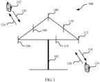
- FIG. 1 is a schematic diagram of a communications system for non-orthogonal data transmission to which this application is applied.
- the communications system 100 includes a network device 102, and the network device 102 may include a plurality of antennas such as antennas 104, 106, 108, 110, 112, and 114.
- the network device 102 may additionally include a transmitter chain and a receiver chain.
- both the transmitter chain and the receiver chain may include a plurality of components that are related to signal transmission and reception (such as a processor, a modulator, a multiplexer, a demodulator, a demultiplexer, or an antenna).
- the network device 102 may communicate with a plurality of terminal devices (such as a terminal device 116 and a terminal device 122). However, it can be understood that the network device 102 may communicate with any quantity of terminal devices similar to the terminal device 116 or 122.
- the terminal devices 116 and 122 may be cellular phones, smartphones, portable computers, handheld communications devices, handheld computing devices, satellite radio apparatuses, global positioning systems, PDAs, and/or any other appropriate devices that are configured to perform communication in the wireless communications system 100.
- the terminal device 116 communicates with the antennas 112 and 114.
- the antennas 112 and 114 send information to the terminal device 116 through a forward link 118, and receive information from the terminal device 116 through a reverse link 120.
- the terminal device 122 communicates with the antennas 104 and 106.
- the antennas 104 and 106 send information to the terminal device 122 through a forward link 124, and receive information from the terminal device 122 through a reverse link 126.
- FDD Frequency Division Duplex
- a same frequency band may be used on the forward link 118 and the reverse link 120, and a same frequency band may be used on the forward link 124 and the reverse link 126.
- Each antenna (or each antenna group including a plurality of antennas) and/or each region designed for communication are/is referred to as a sector of the network device 102.
- an antenna group may be designed to communicate with a terminal device that is in a sector of a coverage area of the network device 102.
- transmit antennas of the network device 102 may increase signal-to-noise ratios of the forward links 118 and 124 through beamforming.
- a mobile device in a neighboring cell receives less interference.
- the network device 102, the terminal device 116, or the terminal device 122 may be a wireless communications sending apparatus and/or a wireless communications receiving apparatus.
- the wireless communication sending apparatus may encode the data for transmission.
- the wireless communication sending apparatus may obtain (for example, generate, receive from another communications apparatus, or store in a memory) a specific quantity of data bits to be sent to the wireless communication receiving apparatus through a channel.
- Such data bits may be included in a data transport block (or a plurality of transport blocks), and the transport block may be segmented to generate a plurality of code blocks.
- the communications system 100 may be a public land mobile network (Public Land Mobile Network, PLMN), a device-to-device (Device-to-Device, D2D) network, a machine-to-machine (Machine-to-Machine, M2M) network, or another network.
- PLMN Public Land Mobile Network
- D2D device-to-device
- M2M machine-to-machine
- FIG. 1 is merely a simplified schematic diagram used as an example.
- the network may further include another network device that is not graphed in FIG. 1 .
- a transmit end (a receive end) in the embodiments of this application may be a network device.
- the network device may be a device that communicates with a terminal device.
- the network device may be a network device controller.
- Each network device may provide communication coverage to a particular geographical area, and may communicate with a terminal device located in this coverage area (a cell).
- the network device may be a network device (such as a base transceiver station (Base Transceiver Station, BTS)) in a Global System for Mobile Communications (Global System for Mobile Communications, GSM) or a Code Division Multiple Access (Code Division Multiple Access, CDMA) system, may be a network device (NodeB, NB) in a Wideband Code Division Multiple Access (Wideband Code Division Multiple Access, WCDMA) system, or may be an evolved network device (Evolved NodeB, eNB or eNodeB) in an LTE system, or may be a wireless controller in a cloud radio access network (Cloud Radio Access Network, CRAN).
- the network device may be a network device in a future 5G network, a network device in a future evolved public land mobile network (Public Land Mobile Network, PLMN), or the like.
- BTS Base Transceiver Station
- GSM Global System for Mobile Communications
- CDMA Code Division Multiple Access
- NodeB, NB Wideband Code Division Multiple Access
- WCDMA
- a receive end (a transmit end) in the embodiments of this application may be a terminal device.
- the terminal device may be an access terminal, user equipment (User Equipment, UE), a subscriber unit, a subscriber station, a mobile station, a remote station, a remote terminal, a mobile terminal, a user terminal, a terminal, a wireless communications device, a user agent, or a user apparatus.
- User Equipment User Equipment
- the access terminal may be a cellular phone, a cordless phone, a Session Initiation Protocol (Session Initiation Protocol, SIP) phone, a wireless local loop (Wireless Local Loop, WLL) station, a personal digital assistant (Personal Digital Assistant, PDA), a handheld device having a wireless communication function, a computing device, another processing device connected to a wireless modem, an in-vehicle device, a wearable device, a terminal device in the Internet of Things, a virtual reality device, a terminal device in a future 5G network, a terminal device in a future evolved public land mobile network (Public Land Mobile Network, PLMN), or the like.
- SIP Session Initiation Protocol
- WLL Wireless Local Loop
- PDA Personal Digital Assistant
- a non-orthogonal data transmission method and device may be applied to a terminal device or a network device.
- the terminal device or the network device includes a hardware layer, an operating system layer running above the hardware layer, and an application layer running above the operating system layer.
- the hardware layer includes hardware such as a central processing unit (Central Processing Unit, CPU), a memory management unit (Memory Management Unit, MMU), and a memory (which is also referred to as a main memory).
- the operating system may be any one or more types of computer operating systems implementing service processing by using a process (Process), such as a Linux operating system, a Unix operating system, an Android operating system, an iOS operating system, or a Windows operating system.
- the application layer includes applications such as a browser, a contact list, word processing software, and instant messaging software.
- a specific structure of an execution body of a data transmission method is not particularly limited in this application, provided that communication can be performed based on the data transmission method in the embodiments of this application by running a program that records code for the data transmission method in the embodiments of this application.
- an execution body of the data transmission method in the embodiments of this application may be a terminal device or a network device, or may be a function module that is in the terminal device or the network device and that can invoke and execute the program.
- aspects or features of this application may be implemented as a method, an apparatus or a product that uses standard programming and/or engineering technologies.
- the term "product" used in this application covers a computer program that can be accessed from any computer readable component, carrier or medium.
- the computer readable medium may include but is not limited to: a magnetic storage component (such as a hard disk, a floppy disk, or a magnetic tape), an optical disc (such as a compact disc (Compact Disc, CD), a digital versatile disc (Digital Versatile Disc, DVD), a smart card, and a flash memory device (such as erasable programmable read-only memory (Erasable Programmable Read-Only Memory, EPROM), a card, a stick, or a key drive).
- various storage media described in this specification may indicate one or more devices and/or other machine-readable media that are configured to store information.
- the term "machine-readable media” may include but is not limited to a radio channel, and various other media that can store, contain, and/or carry an instruction and/or data.
- a plurality of terminal devices can perform data transmission with a network device by using a same time-frequency resource.
- the time-frequency resource may be a time-frequency resource block (which may also be referred to as a time-frequency resource group) including a plurality of REs.
- locations of the plurality of REs may be the same in time domain (that is, corresponding to a same symbol) and may differ in frequency domain (that is, corresponding to different subcarriers); or locations of the plurality of REs may differ in time domain (that is, corresponding to different symbols) and may be the same in frequency domain (that is, corresponding to a same subcarrier). This is not particularly limited in this application.
- FIG. 2 is a schematic flowchart of a non-orthogonal data transmission method 200 according to an embodiment of this application. As shown in FIG. 2 , the method 200 includes the following content.
- a to-be-transmitted transport block is split into N code blocks with incompletely equal sizes, where N is an integer greater than or equal to 2.
- the N code blocks may be code blocks of different sizes.
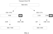
- the TB is split into two code blocks (Code Block, CB): a CB1 and a CB2, respectively.
- code Block, CB code Block
- a parity bit is configured for data bits generated after the TB is split, that is, a cyclic redundancy check (Cyclic Redundancy Check, CRC) code is configured.
- Sizes of the CB1 and the CB2 include a value of the CRC code.
- a size of the CB1 is 5952 bits, and the CB1 includes 24-bit class-B CRC code.
- a size of the CB2 is 2176 bits, and the CB2 includes 24-bit class-A CRC code and the 24-bit class-B CRC code.
- a to-be-transmitted block is split into eight code blocks.
- a CB2 and a CB6 are the same in size
- a CB5 and a CB7 are the same in size
- a CB1, the CB2, a CB3, a CB4, the CB5, and a CB8 are different in size.
- step 202 error correction coding is performed on the N code blocks to obtain N encoded bit blocks.
- error correction coding may be performed on each of the N code blocks in an encoding manner, for example, by using Turbo coding, polar coding, or low-density parity-check coding, to obtain the N encoded bit blocks.
- error correction coding may be performed on the N code blocks in a plurality of encoding manners.
- error correction coding is performed on the N code blocks by using incompletely same code rates, to obtain the N encoded bit blocks.
- sizes of the N code blocks are not completely the same, and the code rates used when error correction coding is performed on the N code blocks is also not completely the same. This embodies that error correction coding with different error correction capabilities is performed on the N code blocks.
- a receive end may gradually demodulate data more easily in an interference cancellation manner.
- error correction coding is first performed on the code block, and rate matching is performed on bits obtained after error correction coding is performed, to obtain the N encoded bit blocks.
- a size of an encoded bit block is a power of 2.
- the N encoded bit blocks are non-orthogonally transmitted by using resources that are the same in at least one dimension of a time domain, a frequency domain, a space domain, and a code domain.
- the same resources may be any type of resource of time domain resources, frequency domain resources, space domain resources, and code domain resources.
- the same resources may be a plurality of types of resources of time domain resources, frequency domain resources, space domain resources, and code domain resources.
- the N encoded bit blocks are combined and non-orthogonally transmitted on the resources that are the same in the at least one dimension.
- the N encoded bit blocks are mapped onto M bit streams, where M is an integer greater than or equal to 1; the M bit streams are modulated to obtain M to-be-transmitted symbol streams, where quantities of modulation symbols in the M to-be-transmitted symbol streams are equal; the M to-be-transmitted symbol streams are superposed to obtain a superposed symbol stream; and the superposed symbol stream is non-orthogonally transmitted.
- the superposed symbol stream is non-orthogonally transmitted by using the resources that are the same in the at least one dimension of the time domain, the frequency domain, the space domain, and the code domain.
- a first bit stream in the M bit streams is modulated through quadrature amplitude modulation and/or phase shift modulation, to obtain the M to-be-transmitted symbol streams.
- the first bit stream may be some of the M bit streams, or may be all of the M bit streams.
- modulating the first bit stream in the M bit streams is modulating bits in the first bit stream.
- the total quantity of time-frequency resources has been obtained when data transmission is performed.
- the order of modulation performed on the first bit stream has been obtained when a modulation scheme is determined.
- the order of modulation performed on the first bit stream may be 4, 16, 64, and 256.
- the TB is split into two CBs: a CB1 and a CB2, respectively.
- a size of the CB1 is 6080 bits, and a size of the CB2 is 4736 bits.
- an EB is obtained after a CB is encoded. During this period, the total quantity of time-frequency resources is 1920.
- An EB1 is obtained after the CB1 is encoded; in this case, an order X of modulation performed on the EB1 is 256, and a size of the EB1 is 15360 bits.
- An EB2 is obtained after the CB2 is encoded; in this case, an order X of modulation performed on the EB2 is 64, and a size of the EB2 is 11520 bits.
- multidimensional modulation is performed on a second bit stream in the M bit streams by using a codebook, where the codebook includes two or more than two code words, the code word is a multidimensional complex vector and is used to represent mapping relationships between data and at least two modulation symbols, and the at least two modulation symbols include at least one zero modulation symbol and at least one non-zero modulation symbol.
- the second bit stream may be some of the M bit streams, or may be all of the M bit streams.
- modulating the second bit stream in the M bit streams is modulating bits in the second bit stream.
- the codebook may be a sparse code multiple access (Sparse Code Multiple Access, SCMA) codebook.
- SCMA Sparse Code Multiple Access
- SCMA is a non-orthogonal multiple access technology.
- a plurality of different data streams are transmitted on a same resource element (that is, the same resource element is used for the plurality of different data streams) by using codebooks, where different codebooks are used for the different data streams. Therefore, resource utilization is improved.
- the data streams may come from same user equipment, or may come from different user equipments.
- the codebook used in SCMA is a set of two or more than two code words.
- the code word may be represented as a multidimensional complex vector of two or more than two dimensions, and is used to represent mapping relationships between data and two or more than two modulation symbols.
- the modulation symbols include at least one zero modulation symbol and at least one non-zero modulation symbol, and the data may be binary bit data or multivariate data.
- the codebook includes two or more than two code words, and the code words may be different from each other.
- the codebook may represent a mapping relationship between a possible data combination of data of a specific length and a code word in the codebook.
- a code word used in SCMA may have sparsity to some extent.
- a quantity of zero elements in the code word may be not less than a quantity of non-zero elements, so that a receive end can use a multi-user detection technology to perform decoding with relatively low complexity.
- the relationship between the quantity of zero elements and the quantity of non-zero elements that is enumerated above is merely an example description of sparsity.
- the present invention is not limited thereto.
- a proportion of the quantity of zero elements to the quantity of non-zero elements may be set at random.
- SCMA Short Term Evolution
- data in a data stream is directly mapped onto a code word, that is, a multidimensional complex vector, in a codebook according to a specific mapping relationship, to implement extended sending of the data over a plurality of resource elements.
- the data herein may be binary bit data or multivariate data.
- the plurality of resource elements may be resource elements in a time domain, a frequency domain, a space domain, a time-frequency domain, a time-space domain, or a time-frequency-space domain. It should be understood that SCMA is only a name, and another name may alternatively be used in the industry to represent the technology.
- the total quantity of time-frequency resources has been obtained when data transmission is performed.
- the order of modulation performed on the second bit stream has been obtained when a modulation scheme is determined.
- the spreading factor F is an optimization parameter used in the SCMA technology.
- the quantity k of bit streams occupied by each encoded bit block EB may be determined based on a mapping relationship of the EB.
- the EB may be mapped sequentially or pseudorandomly.
- the order X of modulation performed on the second bit stream may be an SCMA modulation order, and the order may be 4, 16, 64, and 256.
- the TB is split into two CBs: a CB1 and a CB2, respectively.
- a size of the CB1 is 5952 bits, and a size of the CB2 is 2176 bits.
- an encoded bit block (Encoded Bit, EB) is obtained after a CB is encoded.
- the total quantity of time-frequency resources is 1920
- the spreading factor F is 4, and the quantity k of bit streams occupied by each encoded bit block is 2.
- An EB1 is obtained after the CB1 is encoded; in this case, an order X of modulation performed on the EB1 is 256, and a size of the EB1 is 7680 bits.
- An EB2 is obtained after the CB2 is encoded; in this case, an order X of modulation performed on the EB2 is 16, and a size of the EB2 is 3840 bits.
- the N encoded bit blocks are pseudorandomly mapped onto the M bit streams.
- the N encoded bit blocks are pseudorandomly mapped onto at least two of the M bit streams after each of the N encoded bit blocks is split, or the N encoded bit blocks are pseudorandomly mapped onto at least two of the M bit streams after at least two of the N encoded bit blocks are combined.
- the encoded bit blocks are split, when the first bit stream in the M bit streams is modulated through quadrature amplitude modulation and/or phase shift modulation, as shown in FIG. 7 , for a TB whose size is 8056 bits (that is, a TBS is 8056 bits), the TB is split into two CB: a CB1 and a CB2, respectively.
- a size of the CB1 is 5952 bits, and a size of the CB2 is 2176 bits.
- an EB is obtained after a CB is encoded. During this period, the total quantity of time-frequency resources is 1920.
- An EB1 is obtained after the CB1 is encoded; in this case, an order X of modulation performed on the EB1 is 64, and a size of the EB1 is 11520 bits.
- An EB2 is obtained after the CB2 is encoded; in this case, an order X of modulation performed on the EB2 is 16, and a size of the EB2 is 7680 bits.
- the EB1 is evenly split into two sub-bit blocks that are respectively labeled as a sub-bit block 1 and a sub-bit block 2 according to a splitting sequence, and the sub-bit block 1 and the sub-bit block 2 are randomly mapped onto a bit stream 2 and a bit stream 1.
- the EB2 is evenly split into two sub-bit blocks that are respectively labeled as a sub-bit block 3 and a sub-bit block 4 according to a splitting sequence, and the sub-bit block 3 and the sub-bit block 4 are randomly mapped onto the bit stream 1 and the bit stream 2.
- a bit size of the bit stream 1 is 9600 bits
- a bit size of the bit stream 2 is 9600 bits.
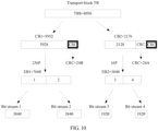
- the TB when multidimensional modulation is performed on the second bit stream in the M bit streams, as shown in FIG. 8 , for a TB whose size is 10744 bits (that is, a TBS is 10744 bits), the TB is unevenly split into two CBs: a CB1 and a CB2, respectively.
- a size of the CB1 is 6080 bits
- a size of the CB2 is 4736 bits.
- an EB is obtained after a CB is encoded.
- the total quantity of time-frequency resources is 1920
- the spreading factor F is 4
- the quantity k of bit streams occupied by each encoded bit block is 3.
- An EB1 is obtained after the CB1 is encoded; in this case, an order X of modulation performed on the EB1 is 256, and a size of the EB1 is 11520 bits.
- An EB2 is obtained after the CB2 is encoded; in this case, an order X of modulation performed on the EB2 is 256, and a size of the EB2 is 11520 bits.
- the EB1 is evenly split into three sub-bit blocks that are respectively labeled as a sub-bit block 1, a sub-bit block 2, and a sub-bit block 3 according to a splitting sequence; and the sub-bit block 1, the sub-bit block 2, and the sub-bit block 3 are randomly mapped onto a bit stream 2, a bit stream 3, and a bit stream 1.
- the EB2 is evenly split into three sub-bit blocks that are respectively labeled as a sub-bit block 4, a sub-bit block 5, and a sub-bit block 6 according to a splitting sequence; and the sub-bit block 4, the sub-bit block 5, and the sub-bit block 6 are respectively mapped onto the bit stream 3, the bit stream 1, and the bit stream 2.
- a bit size of the bit stream 1 is 7680 bits
- a bit size of the bit stream 2 is 7680 bits
- a bit size of the bit stream 3 is 7680 bits.
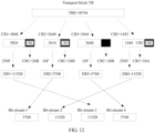
- the total quantity of time-frequency resources is 1920
- the spreading factor F is 4, and the quantity k of bit streams occupied by each encoded bit block is 3.
- An EB1 is obtained after the CB1 is encoded; in this case, an order X of modulation performed on the EB1 is 256, and a size of the EB1 is 11520 bits.
- An EB2 is obtained after the CB2 is encoded; in this case, an order X of modulation performed on the EB2 is 16, and a size of the EB2 is 5760 bits.
- An EB3 is obtained after the CB3 is encoded; in this case, an order X of modulation performed on the EB3 is 16, and a size of the EB3 is 5760 bits.
- An EB4 is obtained after the CB4 is encoded; in this case, an order X of modulation performed on the EB4 is 256, and a size of the EB4 is 11520 bits.
- the EB1 and the EB4 are combined to obtain an EB5, and a size of the EB5 is 23040 bits.
- the EB2 and the EB3 are combined to obtain an EB6, and a size of the EB6 is 11520 bits.
- the EB5 is evenly split into three sub-bit blocks that are respectively labeled as a sub-bit block 1, a sub-bit block 2, and a sub-bit block 3 according to a splitting sequence; and the sub-bit block 1, the sub-bit block 2, and the sub-bit block 3 are respectively mapped onto a bit stream 2, a bit stream 3, and a bit stream 1.
- the EB6 is evenly split into three sub-bit blocks that are respectively labeled as a sub-bit block 4, a sub-bit block 5, and a sub-bit block 6 according to a splitting sequence; and the sub-bit block 4, the sub-bit block 5, and the sub-bit block 6 are respectively mapped onto the bit stream 3, the bit stream 1, and the bit stream 2.
- a bit size of the bit stream 1 is 11520 bits
- a bit size of the bit stream 2 is 11520 bits
- a bit size of the bit stream 3 is 11520 bits.
- the N code blocks are sequentially mapped onto the M bit streams according to an arrangement sequence of bits in each of the N encoded bit blocks.
- the TB is split into two CBs: a CB1 and a CB2, respectively.
- a size of the CB1 is 5952 bits, and a size of the CB2 is 2176 bits.
- an EB is obtained after a CB is encoded.
- the total quantity of time-frequency resources is 1920, the spreading factor F is 4, and the quantity k of bit streams occupied by each encoded bit block is 2.
- An EB1 is obtained after the CB1 is encoded; in this case, an order X of modulation performed on the EB1 is 256, and a size of the EB1 is 7680 bits.
- An EB2 is obtained after the CB2 is encoded; in this case, an order X of modulation performed on the EB2 is 16, and a size of the EB2 is 3840 bits.
- the EB1 is evenly split into two sub-bit blocks that are respectively labeled as a sub-bit block 1 and a sub-bit block 2 according to a splitting sequence, and the sub-bit block 1 and the sub-bit block 2 are respectively mapped onto a bit stream 1 and a bit stream 2.
- the EB2 is evenly split into two sub-bit blocks that are respectively labeled as a sub-bit block 3 and a sub-bit block 4 according to a splitting sequence, and the sub-bit block 3 and the sub-bit block 4 are respectively mapped onto a bit stream 3 and a bit stream 4.
- a bit size of the bit stream 1 is 3840 bits
- a bit size of the bit stream 2 is 3840 bits
- a bit size of the bit stream 3 is 1920 bits
- a bit size of the bit stream 4 is 1920 bits.
- the N code blocks are sequentially mapped onto the M bit streams according to an arrangement sequence of the N encoded bit blocks.
- the TB is split into two CBs: a CB1 and a CB2, respectively.
- a size of the CB1 is 5952 bits, and a size of the CB2 is 2176 bits.
- an EB is obtained after a CB is encoded.
- the total quantity of time-frequency resources is 1920, the spreading factor F is 4, and the quantity k of bit streams occupied by each encoded bit block is 1.
- An EB1 is obtained after the CB1 is encoded; in this case, an order X of modulation performed on the EB1 is 256, and a size of the EB1 is 3840 bits.
- An EB2 is obtained after the CB2 is encoded; in this case, an order X of modulation performed on the EB2 is 16, and a size of the EB2 is 1920 bits.
- the EB1 is mapped onto a bit stream 1 and the EB2 is mapped onto a bit stream 2 according to an arrangement sequence of the N encoded bit blocks.
- a bit block size of the bit stream 1 is 3840 bits, and a bit block size of the bit stream is 1920 bits.
- the N encoded bit blocks are randomly mapped onto the M bit streams.
- M N.
- the TB is unevenly split into four CBs: a CB1, a CB2, a CB3, and a CB4, respectively.
- a size of the CB1 is 3048 bits
- a size of the CB2 is 2640 bits
- a size of the CB3 is 3684 bits
- a size of the CB4 is 1492 bits.
- an EB is obtained after a CB is encoded.
- the total quantity of time-frequency resources is 1920
- the spreading factor F is 4
- the quantity k of bit streams occupied by each encoded bit block is 3.
- An EB1 is obtained after the CB1 is encoded; in this case, an order X of modulation performed on the EB1 is 256, and a size of the EB1 is 11520 bits.
- An EB2 is obtained after the CB2 is encoded; in this case, an order X of modulation performed on the EB2 is 16, and a size of the EB2 is 5760 bits.
- An EB3 is obtained after the CB3 is encoded; in this case, an order X of modulation performed on the EB3 is 16, and a size of the EB3 is 5760 bits.
- An EB4 is obtained after the CB4 is encoded; in this case, an order X of modulation performed on the EB4 is 256, and a size of the EB4 is 11520 bits.
- the EB1 is mapped onto a bit stream 3, the EB2 is mapped onto a bit stream 1, the EB3 is mapped onto a bit stream 4, and the EB4 is mapped onto a bit stream 2.
- the M bit streams are modulated to obtain the M to-be-transmitted symbol streams.
- the quantities of modulation symbols in the M to-be-transmitted symbol streams are equal.
- the M to-be-transmitted symbol streams are superposed to obtain the superposed symbol stream.
- each of the M to-be-transmitted symbol streams includes 10 symbols. Symbols in a first to-be-transmitted symbol stream are labeled as 1a, 2a, ..., and 10a; symbols in a second to-be-transmitted symbol stream are labeled as 1b, 2b, ..., and 10b; symbols in an M th to-be-transmitted symbol stream are labeled as 1M, 2M, ..., and 10M; and symbols in the superposed symbol stream are labeled as 1, 2, ..., and 10.
- the superposed symbol stream is a new symbol stream and may be non-orthogonally transmitted by using same time domain resources, frequency domain resources, space domain resources, and code domain resources.
- the to-be-transmitted block is split into the N code blocks with incompletely equal sizes, and error correction coding with different error correction capabilities is performed on the N code blocks, so that performance of all the code blocks is different, and a receive end can gradually demodulate data more easily in an interference cancellation manner, thereby increasing an uplink/downlink data transmission throughput.
- a received signal is obtained by using the resources that are the same in the at least one dimension of the time domain, the frequency domain, the space domain, and the code domain.
- N encoded bit blocks are obtained by demodulating the received signal, where N is an integer greater than or equal to 2.
- the obtaining N encoded bit blocks by demodulating the received signal includes: obtaining the received signal, where the received signal includes a superposed symbol stream; evenly splitting the superposed symbol stream to obtain M symbol streams, where quantities of symbols included in all of the M symbol streams are equal, and M is an integer greater than or equal to 1; demodulating the M symbol streams to obtain M bit streams; and demapping the M bit streams to obtain the N encoded bit blocks, where N is an integer greater than or equal to 2.
- bits in the M bit streams are pseudorandomly demapped to obtain the N encoded bit blocks.
- bits in the M bit streams are sequentially demapped to obtain the N encoded bit blocks.
- encoded bit blocks in the M bit streams are sequentially mapped onto the N encoded bit blocks according to an arrangement sequence of the encoded bit blocks in the M bit streams.
- bits in the M bit streams are sequentially mapped onto the N encoded bit blocks according to an arrangement sequence of the bits in the M bit streams.
- the M symbol streams are demodulated through quadrature amplitude demodulation and/or phase shift demodulation, to obtain the M bit streams.
- the M symbol streams are demodulated by using a codebook, to obtain the M bit streams, where the codebook includes two or more than two code words, the code word is a multidimensional complex vector and is used to represent mapping relationships between data and at least two modulation symbols, and the at least two modulation symbols include at least one zero modulation symbol and at least one non-zero modulation symbol.
- the codebook includes two or more than two code words
- the code word is a multidimensional complex vector and is used to represent mapping relationships between data and at least two modulation symbols
- the at least two modulation symbols include at least one zero modulation symbol and at least one non-zero modulation symbol.
- demodulation schemes of the M symbol streams are not completely the same.
- error correction decoding is performed on the N encoded bit blocks to obtain N code blocks with incompletely equal sizes.
- error correction decoding is performed on the N encoded bit blocks by using incompletely same code rates, to obtain the N code blocks with incompletely same sizes.
- error correction decoding is performed in any one of the following decoding manners: a Turbo code, a polar code, and a low-density parity-check code.
- the N code blocks are combined to obtain a transport block.
- the N code blocks may be code blocks of incompletely equal sizes.
- the N code blocks with incompletely same sizes are obtained through decoding, so that data is demodulated more easily in an interference cancellation manner, thereby increasing an uplink/downlink data transmission throughput.
- FIG. 14A and FIG. 14B are a schematic flowchart of a non-orthogonal data transmission method 300 according to another non-claimed example.
- the method 300 includes the following content.
- a to-be-transmitted transport block is split into N code blocks, where N is an integer greater than or equal to 2.
- the N code blocks may be code blocks of equal sizes, or may be code blocks of incompletely equal sizes.
- step 302 error correction coding is performed on the N code blocks to obtain N encoded bit blocks.
- error correction coding may be performed on the N code blocks by using incompletely same code rates, to obtain the N encoded bit blocks.
- error correction coding is performed on each of the N code blocks to obtain the N encoded bit blocks, where error correction coding is performed in any one of the following encoding manners: a Turbo code, a polar code, and a low-density parity-check code.
- a size of each of the N encoded bit blocks is a power of 2.
- step 303 the N encoded bit blocks are pseudorandomly mapped onto M bit streams, where M is an integer greater than or equal to 1.
- the N encoded bit blocks are pseudorandomly mapped onto at least two of the M bit streams after each of the N encoded bit blocks is split.
- the N encoded bit blocks are pseudorandomly mapped onto at least two of the M bit streams after at least two of the N encoded bit blocks are combined.
- step 304 the M bit streams are modulated to obtain M to-be-transmitted symbol streams, where quantities of modulation symbols included in all of the M to-be-transmitted symbol streams are equal.
- a first bit stream in the M bit streams is modulated through quadrature amplitude modulation and/or phase shift modulation, to obtain the M to-be-transmitted symbol streams.
- multidimensional modulation is performed on a second bit stream in the M bit streams by using a codebook, where the codebook includes two or more than two code words, the code word is a multidimensional complex vector and is used to represent mapping relationships between data and at least two modulation symbols, and the at least two modulation symbols include at least one zero modulation symbol and at least one non-zero modulation symbol.
- the codebook includes two or more than two code words
- the code word is a multidimensional complex vector and is used to represent mapping relationships between data and at least two modulation symbols
- the at least two modulation symbols include at least one zero modulation symbol and at least one non-zero modulation symbol.
- modulation schemes of the N code blocks are not completely the same.
- step 305 the M to-be-transmitted symbol streams are superposed to obtain a superposed symbol stream.
- the superposed symbol stream is non-orthogonally transmitted by using same time domain resources, frequency domain resources, space domain resources, and code domain resources.
- the to-be-transmitted block is split into the N code blocks, and the N encoded bit blocks are pseudorandomly mapped onto the M bit streams, so that performance of all the bit streams is different, thereby increasing an uplink/downlink data transmission throughput.
- step 307 the superposed symbol stream is received.
- step 308 the superposed symbol stream is evenly split to obtain M symbol streams, where quantities of symbols included in all of the M symbol streams are equal, and M is an integer greater than or equal to 1.
- step 309 the M symbol streams are demodulated to obtain M bit streams.
- the M symbol streams are demodulated through quadrature amplitude demodulation and/or phase shift demodulation, to obtain the M bit streams.
- the M symbol streams are demodulated by using a codebook, to obtain the M bit streams, where the codebook includes two or more than two code words, the code word is a multidimensional complex vector and is used to represent mapping relationships between data and at least two modulation symbols, and the at least two modulation symbols include at least one zero modulation symbol and at least one non-zero modulation symbol.
- the codebook includes two or more than two code words
- the code word is a multidimensional complex vector and is used to represent mapping relationships between data and at least two modulation symbols
- the at least two modulation symbols include at least one zero modulation symbol and at least one non-zero modulation symbol.
- demodulation schemes of the M symbol streams are not completely the same.
- step 310 the M bit streams are demapped to obtain N encoded bit blocks, where N is an integer greater than or equal to 2.
- bits in the M bit streams are pseudorandomly demapped to obtain the N encoded bit blocks.
- step 311 error correction decoding is performed on the N encoded bit blocks to obtain N code blocks.
- error correction decoding is performed on the N encoded bit blocks to obtain the N code blocks, where error correction decoding is performed in any one of the following decoding manners: a Turbo code, a polar code, and a low-density parity-check code.
- step 312 the N code blocks are combined to obtain a transport block.
- bit streams with different performance are obtained, so that data is demodulated more easily in an interference cancellation manner, thereby increasing an uplink/downlink data transmission throughput.
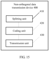
- FIG. 15 is a schematic block diagram of a non-orthogonal data transmission device 400 according to an embodiment of this application. As shown in FIG. 15 , the device 400 includes:
- the transmission unit 430 is specifically configured to:
- the superposed symbol stream is non-orthogonally transmitted by using the resources that are the same in the at least one dimension of the time domain, the frequency domain, the space domain, and the code domain.
- the transmission unit 430 is specifically configured to: pseudorandomly map the N encoded bit blocks onto the M bit streams.
- the transmission unit 430 is specifically configured to:
- the transmission unit 430 is specifically configured to: sequentially map the N encoded bit blocks onto the M bit streams according to an arrangement sequence of the N encoded bit blocks and/or an arrangement sequence of bits in each of the N encoded bit blocks.
- the transmission unit 430 is specifically configured to:
- modulation schemes of the N code blocks are not completely the same.
- the coding unit 420 is specifically configured to: perform error correction coding on the N code blocks by using incompletely same code rates, to obtain the N encoded bit blocks.
- the coding unit 420 performs error correction coding in any one of the following encoding manners: a Turbo code, a polar code, and a low-density parity-check code.
- FIG. 16 is a schematic block diagram of a non-orthogonal data transmission device 500 according to another non-claimed example.
- the device 500 includes:
- mapping unit 530 is specifically configured to: split each of the N encoded bit blocks and pseudorandomly map the N encoded bit blocks onto at least two of the M bit streams; or pseudorandomly map the N encoded bit blocks onto at least two of the M bit streams after at least two of the N encoded bit blocks are combined.
- the modulation unit 540 is specifically configured to:
- modulation schemes of the N code blocks are not completely the same.
- the coding unit 520 is specifically configured to: perform error correction coding on the N code blocks by using incompletely same code rates, to obtain the N encoded bit blocks.
- the coding unit 520 is specifically configured to: perform error correction coding on each of the N code blocks to obtain the N encoded bit blocks, where error correction coding is performed in any one of the following encoding manners: a Turbo code, a polar code, and a low-density parity-check code.
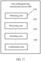
- FIG. 17 is a schematic block diagram of a data transmission device 600 according to an embodiment of this application. As shown in FIG. 17 , the device 600 includes:
- the processing unit 620 is configured to: obtain the received signal, where the received signal includes a superposed symbol stream; evenly split the superposed symbol stream to obtain M symbol streams, where quantities of symbols included in all of the M symbol streams are equal, and M is an integer greater than or equal to 1; demodulate the M symbol streams to obtain M bit streams; and demap the M bit streams to obtain the N encoded bit blocks, where N is an integer greater than or equal to 2.
- the processing unit 620 is configured to pseudorandomly demap bits in the M bit streams to obtain the N encoded bit blocks.
- the processing unit 620 is configured to sequentially demap bits in the M bit streams to obtain the N encoded bit blocks.
- the processing unit 620 is configured to demodulate the M symbol streams through quadrature amplitude demodulation and/or phase shift demodulation, to obtain the M bit streams.
- the processing unit 620 is configured to demodulate the M symbol streams by using a codebook, to obtain the M bit streams, where the codebook includes two or more than two code words, the code word is a multidimensional complex vector and is used to represent mapping relationships between data and at least two modulation symbols, and the at least two modulation symbols include at least one zero modulation symbol and at least one non-zero modulation symbol.
- demodulation schemes of the M symbol streams are not completely the same.
- the decoding unit 630 is configured to: perform error correction decoding on the N code blocks by using incompletely same code rates, to obtain the N code blocks with incompletely same sizes.
- the decoding unit 630 performs error correction decoding in any one of the following decoding manners: a Turbo code, a polar code, and a low-density parity-check code.
- FIG. 18 is a schematic block diagram of a data transmission device 700 according to an embodiment of this application. As shown in FIG. 18 , the device 700 includes:
- the demapping unit 740 is configured to: pseudorandomly demap bits in the M bit streams to obtain the N encoded bit blocks.
- the demapping unit 740 is configured to: sequentially demap bits in the M bit streams to obtain the N encoded bit blocks.
- the demodulation unit 730 is configured to: demodulate the M symbol streams through quadrature amplitude demodulation and/or phase shift demodulation, to obtain the M bit streams.
- the demodulation unit 730 is configured to: demodulate the M symbol streams by using a codebook, to obtain the M bit streams, where the codebook includes two or more than two code words, the code word is a multidimensional complex vector and is used to represent mapping relationships between data and at least two modulation symbols, and the at least two modulation symbols include at least one zero modulation symbol and at least one non-zero modulation symbol.
- the codebook includes two or more than two code words
- the code word is a multidimensional complex vector and is used to represent mapping relationships between data and at least two modulation symbols
- the at least two modulation symbols include at least one zero modulation symbol and at least one non-zero modulation symbol.
- demodulation schemes of the M symbol streams are not completely the same.
- the decoding unit 750 is configured to: perform error correction decoding on the N encoded bit blocks to obtain the N code blocks, where error correction decoding is performed in any one of the following decoding manners: a Turbo code, a polar code, and a low-density parity-check code.
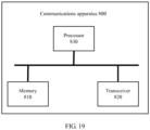
- FIG. 19 is a schematic block diagram of a communications apparatus 800 according to an embodiment of this application.
- the apparatus 800 includes:
- the processor 830 can implement operations performed by a transmit end device in the method 200.
- the communications apparatus 800 may be a terminal device or a network device.
- the transceiver 820 is configured to perform specific signal transceiving under the driving of the processor 830.
- the processor 830 can implement operations performed by a transmit end device in the method 300.
- the communications apparatus 800 may be a terminal device or a network device.
- the processor 830 can implement operations performed by a receive end device in the method 200.
- the communications apparatus 800 may be a terminal device or a network device.
- the transceiver 820 is configured to perform specific signal transceiving under the driving of the processor 830.
- the processor 830 can implement operations performed by a receive end device in the method 300.
- the communications apparatus 800 may be a terminal device or a network device.
- the processor 830 may be a central processing unit (Central Processing Unit, CPU), or the processor 830 may be another general-purpose processor, a digital signal processor (DSP), an application-specific integrated circuit (ASIC), a field programmable gate array (FPGA), or another programmable logic device, discrete gate or transistor logic device, a discrete hardware component, or the like.
- the general-purpose processor may be a microprocessor, or the processor may be any conventional processor or the like.
- the memory 810 may include a read-only memory and a random access memory, and provide an instruction and data to the processor 830.
- a part of the memory 810 may further include a non-volatile random access memory.
- the memory 810 may further store information of a device type.
- the transceiver 820 may be configured to implement signal transmission and reception functions, such as frequency modulation and demodulation functions or up-conversion and down-conversion functions.
- the communications apparatus 800 may be a chip or a chip set.
- the steps of the methods disclosed with reference to the embodiments of this application may be directly performed by a hardware processor, or may be performed by using a combination of hardware in the processor and a software module.
- the software module may be located in a mature storage medium in the art, such as a random access memory, a flash memory, a read-only memory, a programmable read-only memory, an electrically erasable programmable memory, or a register.
- the storage medium is located in the memory, and the processor 830 reads information in the memory and completes the steps in the foregoing methods in combination with hardware of the processor. To avoid repetition, details are not described herein again.
- sequence numbers of the foregoing processes do not mean execution sequences in various embodiments of this application.
- the execution sequences of the processes should be determined based on functions and internal logic of the processes, and should not be construed as any limitation on the implementation processes of the embodiments of this application.
- the disclosed system, apparatus, and method may be implemented in other manners.
- the described apparatus embodiment is merely an example.
- the unit division is merely logical function division and may be other division in actual implementation.
- a plurality of units or components may be combined or integrated into another system, or some features may be ignored or not performed.
- the displayed or discussed mutual couplings or direct couplings or communication connections may be implemented by using some interfaces.
- the indirect couplings or communication connections between the apparatuses or units may be implemented in electrical, mechanical, or other forms.
Landscapes
- Engineering & Computer Science (AREA)
- Signal Processing (AREA)
- Computer Networks & Wireless Communication (AREA)
- Quality & Reliability (AREA)
- Mobile Radio Communication Systems (AREA)
- Digital Transmission Methods That Use Modulated Carrier Waves (AREA)
- Detection And Prevention Of Errors In Transmission (AREA)
Claims (12)
- Vorrichtung zur nichtorthogonalen Übertragung von Daten (400), die Folgendes umfasst:eine Aufteilungseinheit (410), die dazu konfiguriert ist, einen zu übertragenden Transportblock in N Codeblöcke mit nicht völlig gleicher Größe aufzuteilen,wobei N eine ganze Zahl größer oder gleich 2 ist;eine Codiereinheit (420), die dazu konfiguriert ist, eine Fehlerkorrekturcodierung an den N Codeblöcken durchzuführen, um N codierte Bitblöcke zu erlangen; undeine Übertragungseinheit (430), die dazu konfiguriert ist, die N codierten Bitblöcke nichtorthogonal zu übertragen, indem Ressourcen verwendet werden, die in mindestens einer Dimension eines Zeitbereichs, eines Frequenzbereichs, eines Raumbereichs und eines Codebereichs gleich sind, wobei die Übertragungseinheit (430) speziell dazu konfiguriert ist:jeden der N codierten Bitblöcke aufzuteilen und die aufgeteilten N codierten Bitblöcke pseudozufällig auf mindestens zwei von M Bitströmen abzubilden; oderdie N codierten Bitblöcke pseudozufällig auf mindestens zwei von M Bitströmen abzubilden, nachdem mindestens zwei der N codierten Bitblöcke kombiniert wurden, wobei M eine ganze Zahl größer als 1 ist;die M Bitströme zu modulieren, um M zu übertragende Symbolströme zu erlangen, wobei die Mengen der in allen M zu übertragenden Symbolströmen enthaltenen Modulationssymbole gleich sind;die M zu übertragenden Symbolströme zu überlagern, um einen überlagerten Symbolstrom zu erlangen; undden überlagerten Symbolstrom nichtorthogonal zu übertragen.
- Vorrichtung (400) nach Anspruch 1, wobei die Übertragungseinheit (430) speziell konfiguriert ist zum:
Modulieren eines ersten Bitstroms in den M Bitströmen durch Quadraturamplitudenmodulation und/oder Phasenumtastungsmodulation, um die M zu übertragenden Symbolströme zu erlangen. - Vorrichtung (400) nach einem der Ansprüche 1 oder 2, wobei die Modulationsschemata der N Codeblöcke nicht vollständig gleich sind.
- Vorrichtung (400) nach einem der Ansprüche 1 bis 3, wobei die Codiereinheit (420) insbesondere konfiguriert ist zum:
eine Fehlerkorrekturcodierung an den N Codeblöcken durchzuführen, indem unvollständig gleiche Coderaten verwendet werden, um die N codierten Bitblöcke zu erlangen. - System, das die Vorrichtung zur nichtorthogonalen Übertragung von Daten (400) nach einem der Ansprüche 1 bis 4 und eine zweite Vorrichtung zur nichtorthogonalen Übertragung von Daten (600) umfasst, wobei die zweite Vorrichtung zur nichtorthogonalen Übertragung von Daten (600) Folgendes umfasst:eine Erlangungseinheit (610), die dazu konfiguriert ist, unter Verwendung der Ressourcen ein empfangenes Signal zu erlangen, wobei das empfangene Signal den überlagerten Symbolstrom umfasst;eine Verarbeitungseinheit (620), die dazu konfiguriert ist, die N codierten Bitblöcke durch Demodulieren des empfangenen Signals zu erlangen;eine Decodiereinheit (630), die dazu konfiguriert ist, eine Fehlerkorrekturdecodierung an den N codierten Bitblöcken durchzuführen, um die N Codeblöcke zu erlangen; undeine Kombinationseinheit (640), die dazu konfiguriert ist, die N Codeblöcke zu kombinieren, um den Transportblock zu erlangen, wobei die Verarbeitungseinheit (620) der zweiten Vorrichtung zur nichtorthogonalen Übertragung von Daten (600) speziell konfiguriert ist zum:
Erlangen des überlagerten Symbolstroms im empfangenen Signal; gleichmäßigen Aufteilen des überlagerten Symbolstroms, um die M Symbolströme zu erlangen; Demodulieren der M Symbolströme, um die M Bitströme zu erlangen; und pseudozufälligen Rückbilden von Bits in den M Bitströmen, um die N codierten Bitblöcke zu erlangen. - System nach Anspruch 5, wobei die Verarbeitungseinheit (620) der zweiten Vorrichtung zur nichtorthogonalen Übertragung von Daten (600) speziell konfiguriert ist zum:
Demodulieren der M Symbolströme durch Quadraturamplitudendemodulation und/oder Phasenumtastungsdemodulation, um die M Bitströme zu erlangen. - System nach einem der Ansprüche 5 oder 6, wobei die Demodulationsschemata der M Symbolströme nicht vollständig gleich sind.
- Verfahren zur nichtorthogonalen Datenübertragung, umfassend:Aufteilen eines zu übertragenden Transportblocks in N Codeblöcke mit nicht völlig gleicher Größe,wobei N eine ganze Zahl größer oder gleich 2 ist;Durchführen einer Fehlerkorrekturcodierung an den N Codeblöcken, um N codierte Bitblöcke zu erlangen; undnichtorthogonales Übertragen der N codierten Bitblöcke, indem Ressourcen verwendet werden, die in mindestens einer Dimension eines Zeitbereichs, eines Frequenzbereichs, eines Raumbereichs und eines Codebereichs gleich sind, wobei das Verfahren ferner Folgendes umfasst:Aufteilen jedes der N codierten Bitblöcke und pseudozufälliges Abbilden der aufgeteilten N codierten Bitblöcke auf mindestens zwei von M Bitströmen; oderpseudozufälliges Abbilden der N codierten Bitblöcke auf mindestens zwei von M Bitströmen, nachdem mindestens zwei der N codierten Bitblöcke kombiniert wurden, wobei M eine ganze Zahl größer als 1 ist;Modulieren der M Bitströme, um M zu übertragende Symbolströme zu erlangen, wobei die Mengen der in allen M zu übertragenden Symbolströmen enthaltenen Modulationssymbole gleich sind;Überlagern der M zu übertragenden Symbolströme, um einen überlagerten Symbolstrom zu erlangen; undnichtorthogonales Übertragen des überlagerten Symbolstroms.
- Verfahren nach Anspruch 8, ferner umfassend:
Modulieren eines ersten Bitstroms in den M Bitströmen durch Quadraturamplitudenmodulation und/oder Phasenumtastungsmodulation, um die M zu übertragenden Symbolströme zu erlangen. - Verfahren nach einem der Ansprüche 8 oder 9, wobei die Modulationsschemata der N Codeblöcke nicht vollständig gleich sind.
- Verfahren nach einem der Ansprüche 8 bis 10, ferner umfassend:
Durchführen einer Fehlerkorrekturcodierung an den N Codeblöcken, indem unvollständig gleiche Coderaten verwendet werden, um die N codierten Bitblöcke zu erlangen. - Computerspeichermedium, wobei das Computerspeichermedium Programmcode speichert, der, wenn er von einem Computer einer Vorrichtung ausgeführt wird, die Vorrichtung dazu veranlasst, das Verfahren nach einem der Ansprüche 8 bis 11 durchzuführen.
Applications Claiming Priority (2)
| Application Number | Priority Date | Filing Date | Title |
|---|---|---|---|
| CN201611215766.7A CN108242972B (zh) | 2016-12-26 | 2016-12-26 | 非正交传输数据的方法和设备 |
| PCT/CN2017/118175 WO2018121460A1 (zh) | 2016-12-26 | 2017-12-25 | 非正交传输数据的方法和设备 |
Publications (3)
| Publication Number | Publication Date |
|---|---|
| EP3550747A1 EP3550747A1 (de) | 2019-10-09 |
| EP3550747A4 EP3550747A4 (de) | 2019-11-27 |
| EP3550747B1 true EP3550747B1 (de) | 2025-04-23 |
Family
ID=62704949
Family Applications (1)
| Application Number | Title | Priority Date | Filing Date |
|---|---|---|---|
| EP17886801.4A Active EP3550747B1 (de) | 2016-12-26 | 2017-12-25 | Verfahren und vorrichtung zur nichtorthogonalen übertragung von daten |
Country Status (5)
| Country | Link |
|---|---|
| US (1) | US10924211B2 (de) |
| EP (1) | EP3550747B1 (de) |
| JP (1) | JP2020503758A (de) |
| CN (1) | CN108242972B (de) |
| WO (1) | WO2018121460A1 (de) |
Families Citing this family (9)
| Publication number | Priority date | Publication date | Assignee | Title |
|---|---|---|---|---|
| US11140018B2 (en) * | 2014-01-07 | 2021-10-05 | Quantumsine Acquisitions Inc. | Method and apparatus for intra-symbol multi-dimensional modulation |
| CN111884787B (zh) * | 2018-07-30 | 2022-03-29 | 上海朗帛通信技术有限公司 | 一种被用于无线通信的用户设备、基站中的方法和装置 |
| CN115412218A (zh) * | 2018-11-23 | 2022-11-29 | 上海朗帛通信技术有限公司 | 一种被用于无线通信的用户设备、基站中的方法和装置 |
| CN111371530B (zh) * | 2018-12-26 | 2022-03-25 | 海思光电子有限公司 | 一种正交振幅调制qam信号调制和解调方法及装置 |
| CN110048985A (zh) * | 2019-03-27 | 2019-07-23 | 天津大学 | 次优的低复杂度scma码本设计方法 |
| CN111901271B (zh) * | 2020-05-13 | 2021-08-31 | 华中科技大学 | 一种数据传输方法及装置 |
| CN112087247B (zh) * | 2020-08-04 | 2021-10-08 | 西安电子科技大学 | 一种基于大规模mimo-otfs的径分多址接入方法 |
| WO2023039806A1 (zh) * | 2021-09-16 | 2023-03-23 | Oppo广东移动通信有限公司 | 数据传输方法、装置、设备及存储介质 |
| CN116437386A (zh) * | 2021-12-31 | 2023-07-14 | 华为技术有限公司 | 一种通信方法及相关装置 |
Family Cites Families (16)
| Publication number | Priority date | Publication date | Assignee | Title |
|---|---|---|---|---|
| US7190732B2 (en) * | 2000-04-06 | 2007-03-13 | Lucent Technologies Inc. | Multilevel coding with unequal error protection and time diversity for bandwidth efficient transmission |
| US7558191B2 (en) * | 2006-09-07 | 2009-07-07 | Alcatel-Lucent Usa Inc. | Method of OFDM communication using superposition coding |
| WO2009039638A1 (en) * | 2007-09-28 | 2009-04-02 | Pin-Han Ho | A robust system and method for wireless data multicasting using superposition modulation |
| JP5894105B2 (ja) * | 2013-04-04 | 2016-03-23 | 株式会社Nttドコモ | 無線基地局、ユーザ端末及び無線通信方法 |
| US10075266B2 (en) * | 2013-10-09 | 2018-09-11 | Qualcomm Incorporated | Data transmission scheme with unequal code block sizes |
| US10117120B2 (en) * | 2014-10-28 | 2018-10-30 | Qualcomm Incorporated | Channel feedback for non-orthogonal multiple access systems |
| JP6380071B2 (ja) * | 2014-12-11 | 2018-08-29 | ソニー株式会社 | 通信制御装置、無線通信装置、通信制御方法及び無線通信方法 |
| KR102056746B1 (ko) * | 2014-12-22 | 2019-12-17 | 후아웨이 테크놀러지 컴퍼니 리미티드 | 지시 정보를 전송하는 방법 및 장치 |
| EP3226637B1 (de) * | 2014-12-22 | 2019-06-12 | Huawei Technologies Co., Ltd. | Verfahren und vorrichtung zur übertragung von indikationsinformationen |
| CN105991227B (zh) * | 2015-02-15 | 2020-03-03 | 中兴通讯股份有限公司 | 数据编码方法及装置 |
| KR102299864B1 (ko) * | 2015-03-13 | 2021-09-08 | 삼성전자주식회사 | 비직교 송신 신호를 사용하는 다중 반송파 시스템에서 가변 관찰 길이를 사용해 신호를 송수신하는 방법 및 장치 |
| US10104674B2 (en) * | 2015-11-06 | 2018-10-16 | Hfi Innovation Inc. | Rate assignment with rate splitting for interference cancellation friendly new air interface |
| CN105610560B (zh) * | 2015-12-28 | 2018-09-07 | 哈尔滨工业大学 | 一种基于稀疏码多址接入的全双工中继系统的构建方法 |
| CN105472752B (zh) * | 2016-01-21 | 2019-05-28 | 清华大学 | 一种上行随机接入方法 |
| EP3466177B1 (de) * | 2016-05-26 | 2026-04-08 | Nokia Technologies Oy | Codewortanpassung für nichtorthogonalen codierten zugang |
| US11336343B2 (en) * | 2017-06-13 | 2022-05-17 | Lg Electronics Inc. | Method and device for performing communication using orthogonal or nonorthogonal code multiple access scheme in wireless communication system |
-
2016
- 2016-12-26 CN CN201611215766.7A patent/CN108242972B/zh active Active
-
2017
- 2017-12-25 EP EP17886801.4A patent/EP3550747B1/de active Active
- 2017-12-25 WO PCT/CN2017/118175 patent/WO2018121460A1/zh not_active Ceased
- 2017-12-25 JP JP2019534682A patent/JP2020503758A/ja not_active Ceased
-
2019
- 2019-06-25 US US16/452,107 patent/US10924211B2/en active Active
Also Published As
| Publication number | Publication date |
|---|---|
| WO2018121460A1 (zh) | 2018-07-05 |
| US20190319743A1 (en) | 2019-10-17 |
| CN108242972B (zh) | 2020-12-15 |
| US10924211B2 (en) | 2021-02-16 |
| EP3550747A4 (de) | 2019-11-27 |
| CN108242972A (zh) | 2018-07-03 |
| EP3550747A1 (de) | 2019-10-09 |
| JP2020503758A (ja) | 2020-01-30 |
Similar Documents
| Publication | Publication Date | Title |
|---|---|---|
| US10924211B2 (en) | Non-orthogonal data transmission method and device | |
| US10158404B2 (en) | Data transmission method, transmit end device, and receive end device | |
| KR102627637B1 (ko) | 무선 통신 시스템에서 프런트 홀 전송을 위한 장치 및 방법 | |
| CN111556569A (zh) | 传输上行数据的方法和设备 | |
| WO2016090587A1 (zh) | 数据处理的方法、装置和设备 | |
| WO2019242738A1 (zh) | 发送调制符号的方法、接收调制符号的方法和通信设备 | |
| WO2018228522A1 (zh) | 发送参考信号的方法、接收参考信号的方法和通信装置 | |
| CN107579808A (zh) | 无线通信的方法和装置 | |
| WO2016082123A1 (zh) | 处理数据的方法、网络节点和终端 | |
| US10637612B2 (en) | Information transmission method and apparatus | |
| US20180343093A1 (en) | Signal transmission method and apparatus | |
| CN109391303B (zh) | 处理数据的方法和装置 | |
| CN112153690B (zh) | 通信方法和通信装置 | |
| US10568042B2 (en) | Data transmission method and network device thereof | |
| CN113300815B (zh) | 一种上行数据重复传输的方法及装置 | |
| CN120077615A (zh) | 通信方法及相关装置 | |
| US12580680B2 (en) | Interleaver design for noncoherent reed muller codes | |
| CN115706615A (zh) | 一种通信方法及通信装置 | |
| CN116458236A (zh) | 重复传输数据信道的方法和设备 | |
| WO2018058532A1 (zh) | 数据传输装置、方法以及通信系统 | |
| CN117376071A (zh) | 调制编码的方法和装置 | |
| KR20230116562A (ko) | 무선 통신 시스템에서의 변조 및 복조 방법 및 장치 | |
| KR20250125246A (ko) | Wlan 시스템에서 ppdu에 포함된 시그널 필드를 생성하는 장치 및 방법 | |
| WO2025138181A1 (zh) | 功率指示方法、终端设备和网络设备 | |
| CN120568475A (zh) | 通信方法及通信装置 |
Legal Events
| Date | Code | Title | Description |
|---|---|---|---|
| STAA | Information on the status of an ep patent application or granted ep patent |
Free format text: STATUS: THE INTERNATIONAL PUBLICATION HAS BEEN MADE |
|
| PUAI | Public reference made under article 153(3) epc to a published international application that has entered the european phase |
Free format text: ORIGINAL CODE: 0009012 |
|
| STAA | Information on the status of an ep patent application or granted ep patent |
Free format text: STATUS: REQUEST FOR EXAMINATION WAS MADE |
|
| 17P | Request for examination filed |
Effective date: 20190705 |
|
| AK | Designated contracting states |
Kind code of ref document: A1 Designated state(s): AL AT BE BG CH CY CZ DE DK EE ES FI FR GB GR HR HU IE IS IT LI LT LU LV MC MK MT NL NO PL PT RO RS SE SI SK SM TR |
|
| AX | Request for extension of the european patent |
Extension state: BA ME |
|
| A4 | Supplementary search report drawn up and despatched |
Effective date: 20191030 |
|
| RIC1 | Information provided on ipc code assigned before grant |
Ipc: H04L 27/34 20060101ALI20191024BHEP Ipc: H04W 28/04 20090101ALI20191024BHEP Ipc: H04L 1/00 20060101AFI20191024BHEP |
|
| DAV | Request for validation of the european patent (deleted) | ||
| DAX | Request for extension of the european patent (deleted) | ||
| STAA | Information on the status of an ep patent application or granted ep patent |
Free format text: STATUS: EXAMINATION IS IN PROGRESS |
|
| 17Q | First examination report despatched |
Effective date: 20210812 |
|
| GRAP | Despatch of communication of intention to grant a patent |
Free format text: ORIGINAL CODE: EPIDOSNIGR1 |
|
| STAA | Information on the status of an ep patent application or granted ep patent |
Free format text: STATUS: GRANT OF PATENT IS INTENDED |
|
| INTG | Intention to grant announced |
Effective date: 20240716 |
|
| GRAJ | Information related to disapproval of communication of intention to grant by the applicant or resumption of examination proceedings by the epo deleted |
Free format text: ORIGINAL CODE: EPIDOSDIGR1 |
|
| STAA | Information on the status of an ep patent application or granted ep patent |
Free format text: STATUS: EXAMINATION IS IN PROGRESS |
|
| GRAP | Despatch of communication of intention to grant a patent |
Free format text: ORIGINAL CODE: EPIDOSNIGR1 |
|
| STAA | Information on the status of an ep patent application or granted ep patent |
Free format text: STATUS: GRANT OF PATENT IS INTENDED |
|
| INTC | Intention to grant announced (deleted) | ||
| INTG | Intention to grant announced |
Effective date: 20241205 |
|
| GRAS | Grant fee paid |
Free format text: ORIGINAL CODE: EPIDOSNIGR3 |
|
| GRAA | (expected) grant |
Free format text: ORIGINAL CODE: 0009210 |
|
| STAA | Information on the status of an ep patent application or granted ep patent |
Free format text: STATUS: THE PATENT HAS BEEN GRANTED |
|
| AK | Designated contracting states |
Kind code of ref document: B1 Designated state(s): AL AT BE BG CH CY CZ DE DK EE ES FI FR GB GR HR HU IE IS IT LI LT LU LV MC MK MT NL NO PL PT RO RS SE SI SK SM TR |
|
| REG | Reference to a national code |
Ref country code: GB Ref legal event code: FG4D |
|
| REG | Reference to a national code |
Ref country code: CH Ref legal event code: EP |
|
| REG | Reference to a national code |
Ref country code: DE Ref legal event code: R096 Ref document number: 602017089104 Country of ref document: DE |
|
| REG | Reference to a national code |
Ref country code: IE Ref legal event code: FG4D |
|
| REG | Reference to a national code |
Ref country code: NL Ref legal event code: MP Effective date: 20250423 |
|
| PG25 | Lapsed in a contracting state [announced via postgrant information from national office to epo] |
Ref country code: NL Free format text: LAPSE BECAUSE OF FAILURE TO SUBMIT A TRANSLATION OF THE DESCRIPTION OR TO PAY THE FEE WITHIN THE PRESCRIBED TIME-LIMIT Effective date: 20250423 |
|
| REG | Reference to a national code |
Ref country code: AT Ref legal event code: MK05 Ref document number: 1788832 Country of ref document: AT Kind code of ref document: T Effective date: 20250423 |
|
| PG25 | Lapsed in a contracting state [announced via postgrant information from national office to epo] |
Ref country code: FI Free format text: LAPSE BECAUSE OF FAILURE TO SUBMIT A TRANSLATION OF THE DESCRIPTION OR TO PAY THE FEE WITHIN THE PRESCRIBED TIME-LIMIT Effective date: 20250423 Ref country code: ES Free format text: LAPSE BECAUSE OF FAILURE TO SUBMIT A TRANSLATION OF THE DESCRIPTION OR TO PAY THE FEE WITHIN THE PRESCRIBED TIME-LIMIT Effective date: 20250423 Ref country code: PT Free format text: LAPSE BECAUSE OF FAILURE TO SUBMIT A TRANSLATION OF THE DESCRIPTION OR TO PAY THE FEE WITHIN THE PRESCRIBED TIME-LIMIT Effective date: 20250825 |
|
| REG | Reference to a national code |
Ref country code: LT Ref legal event code: MG9D |
|
| PG25 | Lapsed in a contracting state [announced via postgrant information from national office to epo] |
Ref country code: GR Free format text: LAPSE BECAUSE OF FAILURE TO SUBMIT A TRANSLATION OF THE DESCRIPTION OR TO PAY THE FEE WITHIN THE PRESCRIBED TIME-LIMIT Effective date: 20250724 Ref country code: NO Free format text: LAPSE BECAUSE OF FAILURE TO SUBMIT A TRANSLATION OF THE DESCRIPTION OR TO PAY THE FEE WITHIN THE PRESCRIBED TIME-LIMIT Effective date: 20250723 |
|
| PG25 | Lapsed in a contracting state [announced via postgrant information from national office to epo] |
Ref country code: PL Free format text: LAPSE BECAUSE OF FAILURE TO SUBMIT A TRANSLATION OF THE DESCRIPTION OR TO PAY THE FEE WITHIN THE PRESCRIBED TIME-LIMIT Effective date: 20250423 |
|
| PG25 | Lapsed in a contracting state [announced via postgrant information from national office to epo] |
Ref country code: BG Free format text: LAPSE BECAUSE OF FAILURE TO SUBMIT A TRANSLATION OF THE DESCRIPTION OR TO PAY THE FEE WITHIN THE PRESCRIBED TIME-LIMIT Effective date: 20250423 |
|
| PG25 | Lapsed in a contracting state [announced via postgrant information from national office to epo] |
Ref country code: HR Free format text: LAPSE BECAUSE OF FAILURE TO SUBMIT A TRANSLATION OF THE DESCRIPTION OR TO PAY THE FEE WITHIN THE PRESCRIBED TIME-LIMIT Effective date: 20250423 |
|
| PG25 | Lapsed in a contracting state [announced via postgrant information from national office to epo] |
Ref country code: AT Free format text: LAPSE BECAUSE OF FAILURE TO SUBMIT A TRANSLATION OF THE DESCRIPTION OR TO PAY THE FEE WITHIN THE PRESCRIBED TIME-LIMIT Effective date: 20250423 |
|
| PG25 | Lapsed in a contracting state [announced via postgrant information from national office to epo] |
Ref country code: RS Free format text: LAPSE BECAUSE OF FAILURE TO SUBMIT A TRANSLATION OF THE DESCRIPTION OR TO PAY THE FEE WITHIN THE PRESCRIBED TIME-LIMIT Effective date: 20250723 |
|
| PG25 | Lapsed in a contracting state [announced via postgrant information from national office to epo] |
Ref country code: IS Free format text: LAPSE BECAUSE OF FAILURE TO SUBMIT A TRANSLATION OF THE DESCRIPTION OR TO PAY THE FEE WITHIN THE PRESCRIBED TIME-LIMIT Effective date: 20250823 |
|
| PG25 | Lapsed in a contracting state [announced via postgrant information from national office to epo] |
Ref country code: LV Free format text: LAPSE BECAUSE OF FAILURE TO SUBMIT A TRANSLATION OF THE DESCRIPTION OR TO PAY THE FEE WITHIN THE PRESCRIBED TIME-LIMIT Effective date: 20250423 |
|
| PGFP | Annual fee paid to national office [announced via postgrant information from national office to epo] |
Ref country code: DE Payment date: 20251104 Year of fee payment: 9 |
|
| PGFP | Annual fee paid to national office [announced via postgrant information from national office to epo] |
Ref country code: GB Payment date: 20251114 Year of fee payment: 9 |
|
| PG25 | Lapsed in a contracting state [announced via postgrant information from national office to epo] |
Ref country code: SM Free format text: LAPSE BECAUSE OF FAILURE TO SUBMIT A TRANSLATION OF THE DESCRIPTION OR TO PAY THE FEE WITHIN THE PRESCRIBED TIME-LIMIT Effective date: 20250423 Ref country code: DK Free format text: LAPSE BECAUSE OF FAILURE TO SUBMIT A TRANSLATION OF THE DESCRIPTION OR TO PAY THE FEE WITHIN THE PRESCRIBED TIME-LIMIT Effective date: 20250423 |
|
| PG25 | Lapsed in a contracting state [announced via postgrant information from national office to epo] |
Ref country code: CZ Free format text: LAPSE BECAUSE OF FAILURE TO SUBMIT A TRANSLATION OF THE DESCRIPTION OR TO PAY THE FEE WITHIN THE PRESCRIBED TIME-LIMIT Effective date: 20250423 |
|
| PG25 | Lapsed in a contracting state [announced via postgrant information from national office to epo] |
Ref country code: EE Free format text: LAPSE BECAUSE OF FAILURE TO SUBMIT A TRANSLATION OF THE DESCRIPTION OR TO PAY THE FEE WITHIN THE PRESCRIBED TIME-LIMIT Effective date: 20250423 |
|
| REG | Reference to a national code |
Ref country code: DE Ref legal event code: R097 Ref document number: 602017089104 Country of ref document: DE |
|
| PG25 | Lapsed in a contracting state [announced via postgrant information from national office to epo] |
Ref country code: RO Free format text: LAPSE BECAUSE OF FAILURE TO SUBMIT A TRANSLATION OF THE DESCRIPTION OR TO PAY THE FEE WITHIN THE PRESCRIBED TIME-LIMIT Effective date: 20250423 Ref country code: SK Free format text: LAPSE BECAUSE OF FAILURE TO SUBMIT A TRANSLATION OF THE DESCRIPTION OR TO PAY THE FEE WITHIN THE PRESCRIBED TIME-LIMIT Effective date: 20250423 |
|
| PG25 | Lapsed in a contracting state [announced via postgrant information from national office to epo] |
Ref country code: IT Free format text: LAPSE BECAUSE OF FAILURE TO SUBMIT A TRANSLATION OF THE DESCRIPTION OR TO PAY THE FEE WITHIN THE PRESCRIBED TIME-LIMIT Effective date: 20250423 |
|
| PLBE | No opposition filed within time limit |
Free format text: ORIGINAL CODE: 0009261 |
|
| STAA | Information on the status of an ep patent application or granted ep patent |
Free format text: STATUS: NO OPPOSITION FILED WITHIN TIME LIMIT |
|
| REG | Reference to a national code |
Ref country code: CH Ref legal event code: L10 Free format text: ST27 STATUS EVENT CODE: U-0-0-L10-L00 (AS PROVIDED BY THE NATIONAL OFFICE) Effective date: 20260304 |
|
| 26N | No opposition filed |
Effective date: 20260126 |