EP3550599B1 - Bonder - Google Patents
Bonder Download PDFInfo
- Publication number
- EP3550599B1 EP3550599B1 EP17875533.6A EP17875533A EP3550599B1 EP 3550599 B1 EP3550599 B1 EP 3550599B1 EP 17875533 A EP17875533 A EP 17875533A EP 3550599 B1 EP3550599 B1 EP 3550599B1
- Authority
- EP
- European Patent Office
- Prior art keywords
- chuck unit
- base
- chuck
- bonding
- chamber
- Prior art date
- Legal status (The legal status is an assumption and is not a legal conclusion. Google has not performed a legal analysis and makes no representation as to the accuracy of the status listed.)
- Active
Links
- 230000007246 mechanism Effects 0.000 claims description 186
- 238000000034 method Methods 0.000 claims description 2
- 230000001419 dependent effect Effects 0.000 claims 1
- 230000009471 action Effects 0.000 description 28
- 230000033001 locomotion Effects 0.000 description 18
- 238000001816 cooling Methods 0.000 description 16
- 238000007789 sealing Methods 0.000 description 16
- 230000005540 biological transmission Effects 0.000 description 15
- 230000002093 peripheral effect Effects 0.000 description 15
- 230000006835 compression Effects 0.000 description 7
- 238000007906 compression Methods 0.000 description 7
- 239000002826 coolant Substances 0.000 description 6
- 238000005188 flotation Methods 0.000 description 6
- 230000015572 biosynthetic process Effects 0.000 description 5
- 230000037361 pathway Effects 0.000 description 5
- 230000000149 penetrating effect Effects 0.000 description 4
- 230000009467 reduction Effects 0.000 description 3
- 230000004044 response Effects 0.000 description 3
- 239000000853 adhesive Substances 0.000 description 2
- 230000001070 adhesive effect Effects 0.000 description 2
- 230000033228 biological regulation Effects 0.000 description 2
- 230000008859 change Effects 0.000 description 2
- 239000007788 liquid Substances 0.000 description 2
- 230000001105 regulatory effect Effects 0.000 description 2
- 230000007306 turnover Effects 0.000 description 2
- 239000000919 ceramic Substances 0.000 description 1
- 230000001276 controlling effect Effects 0.000 description 1
- 230000002950 deficient Effects 0.000 description 1
- 238000001514 detection method Methods 0.000 description 1
- 230000000694 effects Effects 0.000 description 1
- 238000010438 heat treatment Methods 0.000 description 1
- 230000014759 maintenance of location Effects 0.000 description 1
- 238000004519 manufacturing process Methods 0.000 description 1
- 238000003825 pressing Methods 0.000 description 1
- 230000008569 process Effects 0.000 description 1
- 238000000926 separation method Methods 0.000 description 1
- 230000001360 synchronised effect Effects 0.000 description 1
Images


Classifications
-
- H—ELECTRICITY
- H01—ELECTRIC ELEMENTS
- H01L—SEMICONDUCTOR DEVICES NOT COVERED BY CLASS H10
- H01L24/00—Arrangements for connecting or disconnecting semiconductor or solid-state bodies; Methods or apparatus related thereto
- H01L24/74—Apparatus for manufacturing arrangements for connecting or disconnecting semiconductor or solid-state bodies
- H01L24/75—Apparatus for connecting with bump connectors or layer connectors
-
- H—ELECTRICITY
- H01—ELECTRIC ELEMENTS
- H01L—SEMICONDUCTOR DEVICES NOT COVERED BY CLASS H10
- H01L21/00—Processes or apparatus adapted for the manufacture or treatment of semiconductor or solid state devices or of parts thereof
- H01L21/67—Apparatus specially adapted for handling semiconductor or electric solid state devices during manufacture or treatment thereof; Apparatus specially adapted for handling wafers during manufacture or treatment of semiconductor or electric solid state devices or components ; Apparatus not specifically provided for elsewhere
- H01L21/683—Apparatus specially adapted for handling semiconductor or electric solid state devices during manufacture or treatment thereof; Apparatus specially adapted for handling wafers during manufacture or treatment of semiconductor or electric solid state devices or components ; Apparatus not specifically provided for elsewhere for supporting or gripping
- H01L21/6838—Apparatus specially adapted for handling semiconductor or electric solid state devices during manufacture or treatment thereof; Apparatus specially adapted for handling wafers during manufacture or treatment of semiconductor or electric solid state devices or components ; Apparatus not specifically provided for elsewhere for supporting or gripping with gripping and holding devices using a vacuum; Bernoulli devices
-
- H—ELECTRICITY
- H01—ELECTRIC ELEMENTS
- H01L—SEMICONDUCTOR DEVICES NOT COVERED BY CLASS H10
- H01L21/00—Processes or apparatus adapted for the manufacture or treatment of semiconductor or solid state devices or of parts thereof
- H01L21/02—Manufacture or treatment of semiconductor devices or of parts thereof
- H01L21/04—Manufacture or treatment of semiconductor devices or of parts thereof the devices having at least one potential-jump barrier or surface barrier, e.g. PN junction, depletion layer or carrier concentration layer
- H01L21/18—Manufacture or treatment of semiconductor devices or of parts thereof the devices having at least one potential-jump barrier or surface barrier, e.g. PN junction, depletion layer or carrier concentration layer the devices having semiconductor bodies comprising elements of Group IV of the Periodic System or AIIIBV compounds with or without impurities, e.g. doping materials
- H01L21/185—Joining of semiconductor bodies for junction formation
-
- H—ELECTRICITY
- H01—ELECTRIC ELEMENTS
- H01L—SEMICONDUCTOR DEVICES NOT COVERED BY CLASS H10
- H01L21/00—Processes or apparatus adapted for the manufacture or treatment of semiconductor or solid state devices or of parts thereof
- H01L21/67—Apparatus specially adapted for handling semiconductor or electric solid state devices during manufacture or treatment thereof; Apparatus specially adapted for handling wafers during manufacture or treatment of semiconductor or electric solid state devices or components ; Apparatus not specifically provided for elsewhere
- H01L21/67005—Apparatus not specifically provided for elsewhere
- H01L21/67011—Apparatus for manufacture or treatment
- H01L21/67092—Apparatus for mechanical treatment
-
- H—ELECTRICITY
- H01—ELECTRIC ELEMENTS
- H01L—SEMICONDUCTOR DEVICES NOT COVERED BY CLASS H10
- H01L21/00—Processes or apparatus adapted for the manufacture or treatment of semiconductor or solid state devices or of parts thereof
- H01L21/67—Apparatus specially adapted for handling semiconductor or electric solid state devices during manufacture or treatment thereof; Apparatus specially adapted for handling wafers during manufacture or treatment of semiconductor or electric solid state devices or components ; Apparatus not specifically provided for elsewhere
- H01L21/67005—Apparatus not specifically provided for elsewhere
- H01L21/67242—Apparatus for monitoring, sorting or marking
- H01L21/67259—Position monitoring, e.g. misposition detection or presence detection
-
- H—ELECTRICITY
- H01—ELECTRIC ELEMENTS
- H01L—SEMICONDUCTOR DEVICES NOT COVERED BY CLASS H10
- H01L21/00—Processes or apparatus adapted for the manufacture or treatment of semiconductor or solid state devices or of parts thereof
- H01L21/67—Apparatus specially adapted for handling semiconductor or electric solid state devices during manufacture or treatment thereof; Apparatus specially adapted for handling wafers during manufacture or treatment of semiconductor or electric solid state devices or components ; Apparatus not specifically provided for elsewhere
- H01L21/68—Apparatus specially adapted for handling semiconductor or electric solid state devices during manufacture or treatment thereof; Apparatus specially adapted for handling wafers during manufacture or treatment of semiconductor or electric solid state devices or components ; Apparatus not specifically provided for elsewhere for positioning, orientation or alignment
-
- H—ELECTRICITY
- H01—ELECTRIC ELEMENTS
- H01L—SEMICONDUCTOR DEVICES NOT COVERED BY CLASS H10
- H01L21/00—Processes or apparatus adapted for the manufacture or treatment of semiconductor or solid state devices or of parts thereof
- H01L21/67—Apparatus specially adapted for handling semiconductor or electric solid state devices during manufacture or treatment thereof; Apparatus specially adapted for handling wafers during manufacture or treatment of semiconductor or electric solid state devices or components ; Apparatus not specifically provided for elsewhere
- H01L21/683—Apparatus specially adapted for handling semiconductor or electric solid state devices during manufacture or treatment thereof; Apparatus specially adapted for handling wafers during manufacture or treatment of semiconductor or electric solid state devices or components ; Apparatus not specifically provided for elsewhere for supporting or gripping
- H01L21/6835—Apparatus specially adapted for handling semiconductor or electric solid state devices during manufacture or treatment thereof; Apparatus specially adapted for handling wafers during manufacture or treatment of semiconductor or electric solid state devices or components ; Apparatus not specifically provided for elsewhere for supporting or gripping using temporarily an auxiliary support
-
- H—ELECTRICITY
- H01—ELECTRIC ELEMENTS
- H01L—SEMICONDUCTOR DEVICES NOT COVERED BY CLASS H10
- H01L21/00—Processes or apparatus adapted for the manufacture or treatment of semiconductor or solid state devices or of parts thereof
- H01L21/67—Apparatus specially adapted for handling semiconductor or electric solid state devices during manufacture or treatment thereof; Apparatus specially adapted for handling wafers during manufacture or treatment of semiconductor or electric solid state devices or components ; Apparatus not specifically provided for elsewhere
- H01L21/683—Apparatus specially adapted for handling semiconductor or electric solid state devices during manufacture or treatment thereof; Apparatus specially adapted for handling wafers during manufacture or treatment of semiconductor or electric solid state devices or components ; Apparatus not specifically provided for elsewhere for supporting or gripping
- H01L21/687—Apparatus specially adapted for handling semiconductor or electric solid state devices during manufacture or treatment thereof; Apparatus specially adapted for handling wafers during manufacture or treatment of semiconductor or electric solid state devices or components ; Apparatus not specifically provided for elsewhere for supporting or gripping using mechanical means, e.g. chucks, clamps or pinches
- H01L21/68714—Apparatus specially adapted for handling semiconductor or electric solid state devices during manufacture or treatment thereof; Apparatus specially adapted for handling wafers during manufacture or treatment of semiconductor or electric solid state devices or components ; Apparatus not specifically provided for elsewhere for supporting or gripping using mechanical means, e.g. chucks, clamps or pinches the wafers being placed on a susceptor, stage or support
- H01L21/68764—Apparatus specially adapted for handling semiconductor or electric solid state devices during manufacture or treatment thereof; Apparatus specially adapted for handling wafers during manufacture or treatment of semiconductor or electric solid state devices or components ; Apparatus not specifically provided for elsewhere for supporting or gripping using mechanical means, e.g. chucks, clamps or pinches the wafers being placed on a susceptor, stage or support characterised by a movable susceptor, stage or support, others than those only rotating on their own vertical axis, e.g. susceptors on a rotating caroussel
-
- H—ELECTRICITY
- H01—ELECTRIC ELEMENTS
- H01L—SEMICONDUCTOR DEVICES NOT COVERED BY CLASS H10
- H01L2224/00—Indexing scheme for arrangements for connecting or disconnecting semiconductor or solid-state bodies and methods related thereto as covered by H01L24/00
- H01L2224/74—Apparatus for manufacturing arrangements for connecting or disconnecting semiconductor or solid-state bodies and for methods related thereto
- H01L2224/75—Apparatus for connecting with bump connectors or layer connectors
- H01L2224/751—Means for controlling the bonding environment, e.g. valves, vacuum pumps
- H01L2224/75101—Chamber
- H01L2224/75102—Vacuum chamber
-
- H—ELECTRICITY
- H01—ELECTRIC ELEMENTS
- H01L—SEMICONDUCTOR DEVICES NOT COVERED BY CLASS H10
- H01L2224/00—Indexing scheme for arrangements for connecting or disconnecting semiconductor or solid-state bodies and methods related thereto as covered by H01L24/00
- H01L2224/74—Apparatus for manufacturing arrangements for connecting or disconnecting semiconductor or solid-state bodies and for methods related thereto
- H01L2224/75—Apparatus for connecting with bump connectors or layer connectors
- H01L2224/7525—Means for applying energy, e.g. heating means
- H01L2224/753—Means for applying energy, e.g. heating means by means of pressure
- H01L2224/75301—Bonding head
-
- H—ELECTRICITY
- H01—ELECTRIC ELEMENTS
- H01L—SEMICONDUCTOR DEVICES NOT COVERED BY CLASS H10
- H01L2224/00—Indexing scheme for arrangements for connecting or disconnecting semiconductor or solid-state bodies and methods related thereto as covered by H01L24/00
- H01L2224/74—Apparatus for manufacturing arrangements for connecting or disconnecting semiconductor or solid-state bodies and for methods related thereto
- H01L2224/75—Apparatus for connecting with bump connectors or layer connectors
- H01L2224/758—Means for moving parts
- H01L2224/75821—Upper part of the bonding apparatus, i.e. bonding head
- H01L2224/75824—Translational mechanism
-
- H—ELECTRICITY
- H01—ELECTRIC ELEMENTS
- H01L—SEMICONDUCTOR DEVICES NOT COVERED BY CLASS H10
- H01L2224/00—Indexing scheme for arrangements for connecting or disconnecting semiconductor or solid-state bodies and methods related thereto as covered by H01L24/00
- H01L2224/74—Apparatus for manufacturing arrangements for connecting or disconnecting semiconductor or solid-state bodies and for methods related thereto
- H01L2224/75—Apparatus for connecting with bump connectors or layer connectors
- H01L2224/758—Means for moving parts
- H01L2224/75841—Means for moving parts of the bonding head
- H01L2224/75842—Rotational mechanism
Definitions
- An embodiment of the present invention relates to a bonder according to the pre-characterizing portion of claim 1.
- a bonder is known from US 2014/0311653 A1 .
- chuck units in a pair are arranged one above the other, and suction surfaces for suction of bonding targets are arranged to face each other.
- a driving mechanism such as an actuator (including a ball screw, etc.).
- the conventional bonder has difficulty in applying pressure uniformly to the bonding targets when the bonding targets are caught under pressure. This is caused by the failure to apply pressure uniformly to the chuck unit and resultant deformation such as distortion occurring at the suction surface of the chuck unit.
- At least one embodiment of the present invention is intended to provide a bonder capable of maintaining a high degree of smoothness on a suction surface of a chuck unit.
- the first floating mechanism applies gas pressure to the back surface of the first chuck unit to float the first chuck unit from the first base, thereby moving the suction surface of the first chuck unit toward the suction surface of the second chuck unit.
- a high degree of smoothness can be maintained on a suction surface of a chuck unit.
- FIG. 1 is a conceptual view showing the configuration of a bonder according to a first embodiment.
- the bonder includes a first chuck unit 1A, a second chuck unit 1B, a chamber mechanism 2, a locking mechanism 2L, a first floating mechanism 3A, a second floating mechanism 3B, a rotary mechanism 4, a first biasing mechanism 5A, a second biasing mechanism 5B, and an alignment mechanism 6.
- the first chuck unit 1A and the second chuck unit 1B include a suction surface 11a and a suction surface 11b respectively for suction of bonding targets, and are arranged with the respective suction surfaces 11a and 11b facing each other.
- the first chuck unit 1A is provided with a through hole (not shown in the drawings) formed at a predetermined position (for example, a center position) of the suction surface 11a.
- the suction surface 11a is provided with a slit (not shown in the drawings) extending throughout the suction surface 11a and leading to the through hole. With a bonding target placed on the suction surface 11a, vacuum suction is applied through the through hole.
- the second chuck unit 1B is also provided with a through hole and a slit (not shown in the drawings) similar to those of the first chuck unit 1A to allow the second chuck unit 1B to chuck the bonding target.
- Each of the first chuck unit 1A and the second chuck unit 1B is preferably formed from ceramic having a low thermal expansion coefficient and high heat conductivity.
- the first chuck unit 1A and the second chuck unit 1B are arranged one above the other in the vertical direction in such a manner that the respective suction surfaces 11a and 11b extend horizontally.
- the first chuck unit 1A is arranged below the second chuck unit 1B so as to point the suction surface 11a upwardly.
- the second chuck unit 1B is arranged below the first chuck unit 1A so as to point the suction surface 11b upwardly.
- the upper and lower positions of the first chuck unit 1A and the second chuck unit 1B are switched using the rotary mechanism 4 described later.
- the chamber mechanism 2 includes a first base 21A, a second base 21B, a side wall 22, a driving part 23, and an exhaust part 24.
- the first base 21A is arranged adjacent to a back surface 12a (a surface opposite the suction surface 11a) of the first chuck unit 1A and supports the first chuck unit 1A.
- the second base 21B is arranged adjacent to a back surface 12b (a surface opposite the suction surface 11b) of the second chuck unit 1B and supports the second chuck unit 1B.
- the first base 21A supports the first chuck unit 1A through the first floating mechanism 3A described later.
- a shaft 120A projects from the back surface 12a of the first chuck unit 1A and is slidably inserted into a recessed receiver 210A formed at the first base 21A.
- the second base 21B supports the second chuck unit 1B through the second floating mechanism 3B described later.
- a shaft 120B projects from the back surface 12b of the second chuck unit 1B and is slidably inserted into a recessed receiver 210B formed at the second base 21B.
- a play (gap) for permitting slight tilt of the suction surface 11a of the first chuck unit 1A is provided between the shaft 120A and the receiver 210A.
- play (gap) for permitting slight tilt of the suction surface 11b of the second chuck unit 1B is preferably provided between the shaft 120B and the receiver 210B.
- the first base 21A is allowed to move in a direction perpendicular to the suction surface 11a (or 11b) (in the first embodiment, this direction corresponds to the vertical direction and will be called a "vertical direction" unless otherwise specified).
- This move is realized by the driving part 23.
- a lifting and lowering unit using an air cylinder, for example, is employed as the driving part 23.
- the first base 21A is configured to be movable in the vertical direction relative to the second base 21B.
- the second base 21B may be configured to be movable in the vertical direction relative to the first base 21A.
- both the first base 21A and the second base 21B may be configured to be movable in the vertical direction.
- the chamber mechanism 2 makes the first base 21A and the second base 21B get closer to each other, thereby allowing formation of a chamber 2a (see FIG. 5B ) between the bases.
- the chamber 2a houses the first chuck unit 1A and the second chuck unit 1B inside the chamber 2a and is enclosed. More specifically, making the first base 21A and the second base 21B get closer to each other forms enclosed space surrounded by the first base 21A, the second base 21B, and the side wall 22, and this space becomes the chamber 2a.
- the side wall 22 may be integrated with the first base 21A or the second base 21B. Alternatively, the side wall 22 may be separated from these bases and may be caught between these bases when the first base 21A and the second base 21B get closer to each other.
- the first base 21A, the second base 21B, and the side wall 22 are preferably guided by a guide member to define their move paths in the vertical direction.
- the exhaust part 24 can reduce gas pressure in the chamber 2a until the interior of the chamber 2a is placed in a vacuum.
- a gas pressure regulation device such as a vacuum pump is used as the exhaust part 24, for example.
- the locking mechanism 2L is a mechanism capable of maintaining the positions of the first base 21A and the second base 21B relative to each other at the time of bonding. More specifically, to prevent the chamber 2a from being opened by the moves of the first base 21A and the second base 21B to be farther from each other caused by gas pressures applied to the respective back surfaces 12a and 12b of the first chuck unit 1A and the second chuck unit 1B at the time of bonding, the locking mechanism 2L fixes the positions of the first base 21A and the second base 21B relative to each other.
- the first floating mechanism 3A is a mechanism that floats the first chuck unit 1A from the first base 21A by applying the gas pressure to the back surface 12a of the first chuck unit 1A. By the flotation of the first chuck unit 1A, the suction surface 11a of the first chuck unit 1A is moved toward the suction surface 11b of the second chuck unit 1B.
- the first floating mechanism 3A includes a support 31A and a first gas pressure regulator 32A.
- the support 31A supports the first chuck unit 1A so as to allow flotation of the first chuck unit 1A from the first base 21A, and forms enclosed space 33A between the first base 21A and the first chuck unit 1A.
- the first base 21A includes a facing surface 21Af facing the back surface 12a of the first chuck unit 1A.
- the facing surface 21Af includes a recess 21Ar allowing entry of an end portion of the first chuck unit 1A (an end portion including the back surface 12a) in the vertical direction.
- the opening edge of the recess 21Ar and the outer edge of the back surface 12a of the first chuck unit 1A are connected with a diaphragm as the support 31A. In this way, space enclosed with the diaphragm is formed as the enclosed space 33A between the bottom surface of the recess 21Ar and the back surface 12a of the first chuck unit 1A.
- the first gas pressure regulator 32A can change the state of the interior of the enclosed space 33A from a vacuum state to a pressurized state by changing gas pressure in the enclosed space 33A.
- the first chuck unit 1A is given holding power of attracting the first chuck unit 1A toward the first base 21A.
- increasing the gas pressure in the enclosed space 33A (internal pressure) allows the first chuck unit 1A to be floated from the first base 21A.
- the diaphragm is deformed by following the flotation of the first chuck unit 1A, so that the enclosed state in the enclosed space 33A is maintained without being broken.
- the second floating mechanism 3B is a mechanism that floats the second chuck unit 1B from the second base 21B by applying the gas pressure to the back surface 12b of the second chuck unit 1B.
- the suction surface 11b of the second chuck unit 1B is moved toward the suction surface 11a of the first chuck unit 1A.
- a distance of move of the second chuck unit 1B can be relatively small.
- the second floating mechanism 3B can be a mechanism that floats the second chuck unit 1B slightly from the second base 21B.
- the second floating mechanism 3B includes a support 31B and a second gas pressure regulator 32B.
- the support 31B supports the second chuck unit 1B so as to allow flotation of the second chuck unit 1B from the second base 21B, and forms enclosed space 33B between the second base 21B and the second chuck unit 1B.
- the support 31B is configured using a plurality of pins 311 and a sealing member 312 described below.
- an O-ring is used as the sealing member 312.
- the second floating mechanism 3B may further include a disc spring 52B of the second biasing mechanism 5B described later as a part of the configuration of the second floating mechanism 3B.
- the second chuck unit 1B has a peripheral side surface where a flange 13B is formed to extend on the same plane as the back surface 12b.
- the pins 311 that limit the direction of move of the flange 13B to the vertical direction penetrate the flange 13B.
- the second base 21B includes a facing surface 21Bf facing the back surface 12b of the second chuck unit 1B.
- Each of the pins 311 includes a head 311a and a shaft 311b. With the shaft 311b penetrating the flange 13B, a tip portion of the shaft 311b is fixed to the facing surface 21Bf of the second base 21B.
- the second chuck unit 1B is to move in a limited range between the facing surface 21Bf and the head 311a of the pin 311. Still more specifically, the range of move of the second chuck unit 1B is limited to a range between the disc spring 52B arranged between the head 311a of each pin 311 and the flange 13B of the second chuck unit 1B, and the facing surface 21Bf.
- the flange 13B does not always extend on the same plane as the back surface 12b but can be formed on the peripheral side surface of the second chuck unit 1B and at a different height from the back surface 12b.
- the second base 21B includes a recess 21Br formed inside an annular region 21Bc facing a peripheral region 12c of the back surface 12b of the second chuck unit 1B.
- the elastically deformable sealing member 312 is interposed between the peripheral region 12c and the annular region 21Bc. In this way, space enclosed with the sealing member 312 is formed as the enclosed space 33B between the bottom surface of the recess 21Br and the back surface 12b of the second chuck unit 1B. As long as the enclosed space 33B can be formed between the back surface 12b of the second chuck unit 1B and the second base 21B using the sealing member 312, the recess 21Br is not absolute necessity.
- the second gas pressure regulator 32B can change the state of the interior of the enclosed space 33B from a vacuum state to a pressurized state by changing gas pressure in the enclosed space 33B.
- the second chuck unit 1B is given holding power of attracting the second chuck unit 1B toward the second base 21B.
- increasing the gas pressure in the enclosed space 33B (internal pressure) allows the second chuck unit 1B to be floated from the second base 21B.
- the sealing member 312 is preferably a member that deforms elastically (stretches) by following the flotation of the second chuck unit 1B.
- the rotary mechanism 4 is a mechanism including a rotary axis 41 extending in a direction along the suction surface 11a of the first chuck unit 1A (or the suction surface 11b of the second chuck unit 1B), and capable of switching the positions of the first base 21A and the second base 21B by turning over the chamber mechanism 2 around the rotary axis 41.
- the rotary axis 41 is arranged horizontally and connected to a side surface of the second base 21B.
- the upper and lower positions of the first base 21A and the second base 21B are switched.
- the rotary axis 41 can be used for turning over the chamber mechanism 2, the rotary axis 41 can be connected to a different position (a side surface of the first base 21A, for example) not limited to the second base 21B.
- the first biasing mechanism 5A biases the first chuck unit 1A toward the first base 21A in the vertical direction.
- the first biasing mechanism 5A includes a plurality of first biasing mechanism 5A.
- Each of the first biasing mechanism 5A is composed of a housing chamber 51A, a compression spring 52A, and a pin 53A.
- the housing chamber 51A is formed at the first base 21A.
- the compression spring 52A is housed in the housing chamber 51A so as to be elastically deformable in the vertical direction.
- the pin 53A includes a head 53Aa and a shaft 53Ab, and is arranged so as to place the head 53Aa and the shaft 53Ab in the following states.
- the head 53Aa is located in the housing chamber 51A while abutting on one end of the compression spring 52A (an end opposite the first chuck unit 1A).
- the shaft 53Ab extends toward the first chuck unit 1A in the vertical direction while being passed through the compression spring 52A. Further, the shaft 53Ab penetrates the first base 21A so as to limit a direction of move of the pin 53A to the vertical direction.
- the tip of the shaft 53Ab is connected to the back surface 12a of the first chuck unit 1A.
- the head 53Aa of the pin 53A is biased toward the opposite side of the first chuck unit 1A with the compression spring 52A.
- the first chuck unit 1A is biased toward the first base 21A in the vertical direction through the pin 53A.
- the first chuck unit 1A is arranged above the second chuck unit 1B in the vertical direction. In this state, the gas pressure in the chamber 2a is reduced.
- this holding power is reduced by the reduction in this gas pressure difference.
- the first biasing mechanism 5A applies biasing force to the first chuck unit 1A with which downward move of the first chuck unit 1A under its own weight can be prevented. This makes it possible to attract the first chuck unit 1A toward the first base 21A.
- the second biasing mechanism 5B biases the second chuck unit 1B toward the second base 21B in the vertical direction.
- the second biasing mechanism 5B is composed of the disc spring 52B arranged between the head 311a of each pin 311 and the flange 13B of the second chuck unit 1B.
- the disc spring 52B is arranged with the shaft 311b penetrating the disc spring 52B.
- the second chuck unit 1B is biased toward the second base 21B by the disc spring 52B.
- the second chuck unit 1B is arranged above the first chuck unit 1A in the vertical direction in some cases. Even in such cases, the second biasing mechanism 5B applies biasing force to the second chuck unit 1B with which downward move of the second chuck unit 1B under its own weight can be prevented. This makes it possible to attract the second chuck unit 1B toward the second base 21B.
- FIG. 2A is a perspective view showing the alignment mechanism 6.
- FIG. 2B is a perspective view showing a state of attachment of the alignment mechanism 6 to the chamber mechanism 2.
- FIGS. 3A and 3B are plan views showing the motions of the alignment mechanism 6.
- the alignment mechanism 6 is used for adjusting the positions of bonding targets when these bonding targets are to be chucked on corresponding ones of the first chuck unit 1A and the second chuck unit 1B. More specifically, the alignment mechanism 6 includes a rotary unit 61 with a first rotary axis 61c, three power transmission mechanisms 62, and three alignment action units 63.
- the rotation of the rotary unit 61 is controlled by a rotary driver such as a servo motor capable of detecting and controlling a rotary angle or a torque.
- the three power transmission mechanisms 62 are mechanisms that transmit the rotation of the rotary unit 61 to the three alignment action units 63.
- each of the power transmission mechanisms 62 is a link mechanism.
- the three power transmission mechanisms 62 are pivotably supported at three different positions P11, P12, and P13 at the rotary unit 61 shifted from the first rotary axis 61c.
- the positions P11 to P13 are separated from the first rotary axis 61c by the same distance and arranged at regular intervals (an angular width of 120°) around the first rotary axis 61c.
- the three alignment action units 63 operate in response to transmission of the rotation of the rotary unit 61 through corresponding ones of the three power transmission mechanisms 62, thereby acting on a bonding target to adjust the position of the bonding target.
- Each of the three power transmission mechanisms 62 includes a first arm 621, a second arm 622, a shaft 62C, and a third arm 623.
- the first arm 621 includes a first end 621a pivotably supported at a corresponding one of the three different positions P11 to P13, and a second end 621b located on the opposite side of the first end 621a.
- the second arm 622 includes a second rotary axis 622c and is pivotably supported on the second end 621b of the first arm 621 at a position different from the second rotary axis 622c.
- the second arm 622 includes a first end 622a and a second end 622b. The first end 622a is pivotably supported on the second end 621b of the first arm 621, and the second rotary axis 622c is provided at the second end 622b.
- the respective second rotary axes 622c of the three power transmission mechanisms 62 are arranged at three positions P21, P22, and P23 separated from the rotary unit 61.
- the positions P21 to P23 are arranged in corresponding three different directions centered on the first rotary axis 61c.
- the positions P21 to P23 are arranged at regular intervals (an angular width of 120°) around the first rotary axis 61c along a predetermined circumference centered on the first rotary axis 61c.
- the shaft 62C is connected to the second arm 622 with a center line of the shaft 62C aligned with the second rotary axis 622c. Further, the shaft 62C is pivotably supported on a subject to which the alignment mechanism 6 is attached (in the first embodiment, the second base 21B of the chamber mechanism 2 (see FIG. 2B ). By doing so, the shaft 62C rotates around the second rotary axis 622c in interlocking relationship with the second arm 622 to function as a pivot for the motion of the power transmission mechanism 62.
- the shaft 62C is connected to the second end 622b of the second arm 622. More specifically, the shaft 62C includes a first end 62Ca connected to the second end 622b of the second arm 622, and a second end 62Cb located on the opposite side of the first end 62Ca.
- the third arm 623 is connected to the second end 62Cb of the shaft 62C. In the first embodiment, the third arm 623 includes a first end 623a and a second end 623b. The first end 623a is connected to the second end 62Cb of the shaft 62C.
- the third arm 623 extends from the second end 62Cb of the shaft 62C toward the same direction as the second arm 622 extends from the first end 62Ca of the shaft 62C.
- the third arm 623 is parallel to the second arm 622 and faces the second arm 622.
- the third arm 623 extends to an intermediate position between the first end 622a and the second end 622b of the second arm 622 in a plan view. The direction in which the third arm 623 extends and the position of the tip (second end 623b) of the third arm 623 can be changed, if appropriate.
- the three alignment action units 63 are provided at the respective tips (second ends 623b) of the third arms 623 of corresponding ones of the three power transmission mechanisms 62.
- the three alignment action units 63 are connected to the respective second arms 622 of corresponding ones of the three power transmission mechanisms 62 through the third arms 623 and the shafts 62C.
- a roller pivotably supported on the second end 623b of the third arm 623 is used as each of the alignment action units 63.
- the three second arms 622 can move pivotably in synchronization with each other in response to the rotation of the rotary unit 61 (a direction of the rotation of the rotary unit 61 is indicated by a blank arrow in each of FIGS. 3A and 3B ).
- the synchronized pivotal moves of the second arms 622 are transmitted through corresponding ones of the shafts 62C and third arms 623 to the three alignment action units 63.
- an alignment target (bonding target) is caught from the three directions by the three alignment action units 63 to adjust the position of the alignment target.
- the predetermined position is a destination position where the alignment target has been brought to a state of being caught under pressure uniformly from the three directions through adjustment process by the alignment mechanism 6.
- the alignment mechanism 6 makes the position adjustment through the following torque detection, for example. A torque generated at the rotary unit 61 when the alignment target is caught from the three directions is detected. The alignment target is caught under pressure uniformly from the three directions when the alignment target reaches the predetermined position, so that a torque generated at the rotary unit 61 increases. If the generated torque exceeds a predetermined value, the alignment target is determined to have reached the predetermined position. Then, the position adjustment is finished.
- this rattle can be controlled using reactive force from the alignment target generated by catching the alignment target under pressure from the three directions with an increased torque.
- a high degree of accuracy is achieved in the positioning of the alignment target.
- a disc-shaped object such as a wafer is suitable as the alignment target.
- a shape applicable as the shape of the alignment target can be selected appropriately (for example, a polygonal shape or an oval shape) in response to a degree of accuracy in the position adjustment required during alignment.
- the foregoing alignment mechanism 6 is arranged at the chamber mechanism 2 as follows.
- the rotary unit 61 is arranged on the opposite side of the second chuck unit 1B with respect to the second base 21B, and the three alignment action units 63 are arranged around the suction surface 11b of the second chuck unit 1B (see FIG. 1 ).
- the respective shafts 62C of the three power transmission mechanisms 62 are pivotably supported on the second base 21B while penetrating the second base 21B.
- a bonding target on the suction surface 11b is caught from the three directions by the three alignment action units 63.
- each of the three alignment action units 63 includes a first abutting part 631 and a second abutting part 632 (see FIG. 1 ).
- the first abutting part 631 is to abut on the edge of a bonding target when the position of this bonding target to be sucked on the suction surface 11a of the first chuck unit 1A is adjusted.
- the second abutting part 632 is to abut on the edge of a bonding target when the position of this bonding target to be sucked on the suction surface 11b of the second chuck unit 1B is adjusted.
- the second abutting part 632 is always arranged around the suction surface 11b of the second chuck unit 1B at the same height position as the suction surface 11b.
- the first abutting part 631 is arranged closer to the first base 21A than the second abutting part 632. In the first embodiment, the first abutting part 631 projects inwardly further than the second abutting part 632.
- the first base 21A and the second base 21B get closer to each other to place the first chuck unit 1A at a predetermined position at which the suction surface 11a of the first chuck unit 1A is placed at the same height position as the first abutting part 631.
- the first abutting part 631 projects inwardly further than the second abutting part 632.
- the foregoing alignment mechanism 6 may also be arranged at the chamber mechanism 2 as follows.
- the rotary unit 61 is arranged on the opposite side of the first chuck unit 1A with respect to the first base 21A, and the three alignment action units 63 are arranged around the suction surface 11a of the first chuck unit 1A.
- the respective shafts 62C of the three power transmission mechanisms 62 are pivotably supported on the first base 21A while penetrating the first base 21A. By doing so, it becomes possible to transmit the rotation of the rotary unit 61 to the three alignment action units 63 located on the opposite side of the rotary unit 61 with respect to the first base 21A.
- the second abutting part 632 preferably projects inwardly further than the first abutting part 631.
- FIGS. 4A to 7 show motions in order performed for bonding two bonding targets to each other in the foregoing bonder.
- the first base 21A and the second base 21B are separated from each other to open the chamber 2a, and the second base 21B is arranged below the first base 21A.
- the second chuck unit 1B is arranged below the first chuck unit 1A with the suction surface 11b of the second chuck unit 1B pointed upwardly (see FIG. 4A ).
- the gas pressure in the enclosed space 33B in the second floating mechanism 3B is reduced until the interior of the enclosed space 33B is placed in a vacuum state. This produces the gas pressure difference from outside air, so that the second chuck unit 1B is given holding power of attracting the second chuck unit 1B toward the second base 21B.
- a first bonding target T1 is placed on the suction surface 11b of the second chuck unit 1B (see FIG. 4A ).
- the bonding target T1 is transported to and placed on the suction surface 11b using a transport device such as a transport arm (not shown in the drawings).
- the rotary unit 61 of the alignment mechanism 6 (see FIGS. 2A and 3A ) is rotated clockwise in the plan view of FIG. 3A to move the three alignment action units 63 inwardly.
- the respective second abutting parts 632 of the alignment action units 63 are brought to abutting contacts with the bonding target T1 from the three directions, thereby adjusting the position of the bonding target T1 (see FIGS. 3A and 4B ).
- vacuum suction is applied at the second chuck unit 1B to suck the bonding target T1 on the suction surface 11b. In this way, the bonding target T1 is chucked on the second chuck unit 1B.
- the rotary unit 61 is thereafter rotated anticlockwise (namely, rotated reversely) in the plan view of FIG. 3B (same plan view as FIG. 3A ) to move the three alignment action units 63 outwardly.
- the rotary axis 41 of the rotary mechanism 4 is rotated to turn over the chamber mechanism 2, thereby switching the upper and lower positions of the first base 21A and the second base 21B.
- the first chuck unit 1A is arranged below the second chuck unit 1B with the suction surface 11a of the first chuck unit 1A pointed upwardly (see FIG. 5A ).
- the second biasing mechanism 5B mainly, disc spring 52B
- the second chuck unit 1B is prevented from moving down unintentionally under its own weight.
- the second chuck unit 1B is maintained in a state of being attracted toward the second base 21B.
- the gas pressure in the enclosed space 33A in the first floating mechanism 3A is reduced until the interior of the enclosed space 33A is placed in a vacuum state. This produces the gas pressure difference from outside air, so that the first chuck unit 1A is given holding power of attracting the first chuck unit 1A toward the first base 21A.
- a second bonding target T2 is placed on the suction surface 11a of the first chuck unit 1A (see FIG. 5A ).
- the bonding target T2 is transported to and placed on the suction surface 11a using a transport device such as a transport arm (not shown in the drawings).
- the first base 21A and the second base 21B get closer to each other to form the enclosed chamber 2a (see FIG. 5B ).
- the suction surface 11a of the first chuck unit 1A is placed at the same height position as the first abutting part 631.
- An alignment execution position may be prepared at which the suction surface 11a of the first chuck unit 1A is placed at the same height position as the first abutting part 631 before the formation of the chamber 2a.
- the first base 21A is to be stopped once at the alignment execution position before the formation of the chamber 2a.
- the rotary unit 61 of the alignment mechanism 6 (see FIGS. 2A and 3A ) is rotated to move the three alignment action units 63 inwardly.
- the respective first abutting parts 631 of the alignment action units 63 are brought to abutting contacts with the bonding target T2 from the three directions, thereby adjusting the position of the bonding target T2 (see FIGS. 3A and 6A ).
- the first abutting part 631 projects inwardly further than the second abutting part 632 in each of the alignment action units 63. This allows adjustment of the position of the bonding target T2 on the suction surface 11a using the first abutting part 631 while avoiding contact between the bonding target T1 on the suction surface 11b and the second abutting part 632.
- the torque generated at the rotary unit 61 is thereafter maintained at a predetermined value or more. Specifically, the bonding target T2 is maintained in a state of being caught under pressure from the three directions by the three alignment action units 63 (first abutting parts 631).
- the rotary axis 41 of the rotary mechanism 4 is rotated to turn over the chamber mechanism 2 again, thereby returning the first base 21A and the second base 21B to their original upper and lower positions.
- the first chuck unit 1A is arranged above the second chuck unit 1B (see FIG. 6B ).
- the first biasing mechanism 5A mainly, compression spring 52A
- the first chuck unit 1A is prevented from moving down unintentionally under its own weight.
- the first chuck unit 1A is maintained in a state of being attracted toward the first base 21A.
- the bonding target T2 is maintained in a state of being caught under pressure from the three directions continuously from the time of the position adjustment.
- the gas pressure in the chamber 2a is reduced until the interior of the chamber 2a is placed in a vacuum state. This reduces the upward holding power having acted on the first chuck unit 1A as a result of the gas pressure difference between the gas pressure in the enclosed space 33A and the gas pressure in the chamber 2a. Even on the occurrence of such reduction in the holding power, downward move of the first chuck unit 1A under its own weight is still prevented by the first biasing mechanism 5A. Likewise, reducing the gas pressure in the chamber 2a reduces the power of vacuum-sucking the bonding target T2 on the suction surface 11a.
- the alignment mechanism 6 functions as a holding mechanism that holds the bonding target T2.
- the bonding target T2 may be held by a holding mechanism provided separately from the alignment mechanism 6.
- the gas pressure in the enclosed space 33A (internal pressure) is increased.
- the gas pressure in the enclosed space 33A (internal pressure) is regulated so as to allow the first chuck unit 1A to move down against the biasing force of the first biasing mechanism 5A. In this way, the first chuck unit 1A is floated from the first base 21A (see FIG. 7 ).
- the gas pressure in the enclosed space 33B (internal pressure) is increased.
- the gas pressure in the enclosed space 33B (internal pressure) is regulated so as to allow the second chuck unit 1B to move up against the biasing force of the second biasing mechanism 5B. In this way, the second chuck unit 1B is floated from the second base 21B (see FIG. 7 ).
- the bonding targets T2 and T1 chucked on the suction surfaces 11a are 11b respectively are superimposed on each other.
- the gas pressure in each of the enclosed space 33A and the enclosed space 33B is increased further to press the bonding targets T1 and T2 against each other.
- the two bonding targets T1 and T2 are caught under pressure by the first chuck unit 1A and the second chuck unit 1B and bonded on each other accordingly.
- the gas pressures are applied to the respective back surfaces 12a and 12b of the first chuck unit 1A and the second chuck unit 1B, thereby encouraging uniform application of pressure to the back surfaces 12a and 12b.
- deformation is unlikely to occur at both the suction surfaces 11a and 11b.
- the gas pressures be applied to the back surfaces 12a and 12b of the first chuck unit 1A and the second chuck unit 1B respectively substantially equal to each other by making regulation at the time of bonding so as to place the interior of the enclosed space 33A and that of the enclosed space 33B in substantially equal gas pressure (internal pressure).
- internal pressure gas pressure
- Maintaining a high degree of smoothness on each of the suction surfaces 11a and 11b at the time of bonding allows pressure to be applied uniformly to the bonding targets T1 and T2. As a result, failure such as defective pressure bonding is unlikely to occur at a bonded item composed of the two bonding targets T1 and T2.
- the first biasing mechanism 5A may be configured to generate biasing force using gas pressure.
- FIGS. 8A and 8B are sectional views showing two states in a first example about the first biasing mechanism 5A according to a second embodiment.
- the support 31A of the first floating mechanism 3A is composed of two diaphragms 313 and 314. More specifically, the first chuck unit 1A has a peripheral side surface where a flange 13A is formed to extend on the same plane as the back surface 12a.
- the flange 13A includes a tilted surface 13At on the opposite side of the back surface 12a.
- the flange 13A becomes smaller in thickness at a position closer to the outer edge of the flange 13A.
- a flange 211 is further formed at the opening edge of the recess 21Ar.
- the flange 211 includes a tilted surface 211t substantially parallel to the tilted surface 13At.
- the tilted surfaces 13At and 211t are formed so as not to inhibit the motions of the diaphragms 313 and 314 responsive to the upward and downward moves of the first chuck unit 1A. As long as the motions of the diaphragms 313 and 314 are not inhibited, at least one of the tilted surfaces 13At and 211t can be replaced by a horizontal surface.
- the root position of the flange 13A on the tilted surface 13At and the tip of the flange 211 are connected with the diaphragm 313.
- the tip of the flange 13A and the root position of the flange 211 on the tilted surface 211t are connected with the diaphragm 314.
- space 541 enclosed with the two diaphragms 313 and 314 is formed between the two tilted surfaces 13At and 211t.
- Gas pressure in the space 541 is maintained to be higher at least than the gas pressure in the enclosed space 33A, thereby forming the first biasing mechanism 5A.
- a surface that receives pressure having a vertically upward component occupies an area of an image projected on a virtual horizontal plane larger than an area of an image projected on the virtual horizontal plane about a surface that receives pressure having a vertically downward component (in the second embodiment, this surface corresponds to a surface of the diaphragm 313 facing the space 541).
- principles of generating vertically upward biasing force at the first chuck unit 1A can also be considered as follows.
- the volume of the space 541 becomes maximum (see FIG. 8A ).
- the volume of the space 541 is reduced (see FIG. 8B ).
- the gas pressure in the space 541 increases and force for returning to a state of low pressure is applied as biasing force to the first chuck unit 1A.
- this first biasing mechanism 5A it becomes unnecessary to apply the biasing force of the first biasing mechanism 5A to the back surface 12a of the first chuck unit 1A. This encourages more uniform application of pressure to the back surface 12a. This makes it less likely that deformation such as distortion will occur at the first chuck unit 1A. As a result, it becomes possible to maintain a higher degree of smoothness on the suction surface 11a of the first chuck unit 1A.
- FIGS. 9A and 9B are sectional views showing two states in a second example about the first biasing mechanism 5A according to the second embodiment.
- a flange 14A extending on the same plane as the back surface 12a is formed at the peripheral side surface of the first chuck unit 1A.
- a flange 212 is further formed at the opening edge of the recess 21Ar.
- the flange 14A has an edge surface in sliding contact with the inner side surface of the recess 21Ar.
- the flange 212 has an edge surface in sliding contact with the peripheral side surface of the first chuck unit 1A.
- the edge surface of the flange 14A is provided with a sealing member 551 interposed between this edge surface and the inner side surface of the recess 21Ar.
- the peripheral side surface of the first chuck unit 1A is provided with a sealing member 552 interposed between this peripheral side surface and the edge surface of the flange 212.
- O-rings are used as the sealing members 551 and 552.
- space 542 enclosed with the two sealing members 551 and 552 is formed between the peripheral side surface of the first chuck unit 1A and the inner side surface of the recess 21Ar.
- Gas pressure in the space 542 is maintained to be higher at least than the gas pressure in the enclosed space 33A, thereby forming the first biasing mechanism 5A.
- a surface that receives pressure having a vertically upward component occupies an area of an image projected on a virtual horizontal plane larger than an area of an image projected on the virtual horizontal plane about a surface that receives pressure having a vertically downward component (there is no such a surface in the second embodiment).
- principles of generating vertically upward biasing force at the first chuck unit 1A can also be considered as follows.
- the volume of the space 542 becomes maximum (see FIG. 9A ).
- the volume of the space 542 is reduced (see FIG. 9B ).
- the gas pressure in the space 542 increases and force for returning to a state of low pressure is applied as biasing force to the first chuck unit 1A.
- this biasing mechanism 5A it becomes unnecessary to apply the biasing force of the first biasing mechanism 5A to the back surface 12a of the first chuck unit 1A. This encourages more uniform application of pressure to the back surface 12a. This makes it less likely that deformation such as distortion will occur at the first chuck unit 1A. As a result, it becomes possible to maintain a higher degree of smoothness on the suction surface 11a of the first chuck unit 1A.
- FIG. 10 is a sectional view showing a different example of the second biasing mechanism 5B.
- the second biasing mechanism 5B may be composed of an annular member 561 and an elastic member 562 instead of the pins 311 and the disc spring 52B.
- the annular member 561 is fixed to the facing surface 21Bf of the second base 21B.
- the annular member 561 is formed into a shape extending in an inverted L-shape from the facing surface 21Bf in a cross section to form an annular covering part 561a covering the flange 13B of the second chuck unit 1B.
- the elastic member 562 is an elastically deformable member and is interposed between the flange 13B and the covering part 561a.
- an elastically deformable sealing member O-ring, for example
- the second chuck unit 1B is biased toward the second base 21B by the elastic member 562. If a sealing member is applied to the elastic member 562, the elastic member 562 may take the place of the sealing member 312 to fulfill the function of the sealing member 312 (retention of the enclosed space 33B).
- Two bonding targets may be heated for improving adhesion at the time of bonding, and may be cooled after the bonding is finished.
- the first chuck unit 1A and the second chuck unit 1B include respective built-in heaters. By heating the bonding targets with these heaters, adhesives applied to the bonding targets are melted. After the bonding is finished, the first chuck unit 1A and the second chuck unit 1B themselves are cooled to solidify the adhesives.
- a bonder described in detail below as a fourth embodiment includes cooling mechanisms that cool the first chuck unit 1A and the second chuck unit 1B.
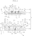
- FIG. 11 is a conceptual view showing the configuration of the bonder according to the fourth embodiment.
- the bonder includes a first cooling mechanism 7A that cools the first chuck unit 1A, and a second cooling mechanism 7B that cools the second chuck unit 1B.
- the first cooling mechanism 7A includes a cooling plate 71A arranged on the back surface 12a of the first chuck unit 1A.
- a pathway 72A for passage of a cooling medium is formed at a surface of the cooling plate 71A in tight contact with the back surface 12a.
- the pathway 72A is configured to avoid leakage of the cooling medium into the enclosed space 33A.
- the cooling medium can either be gas or liquid and can be selected appropriately so as to maintain the first chuck unit 1A at an optimum temperature.
- the second cooling mechanism 7B includes a cooling plate 71B arranged on the back surface 12b of the second chuck unit 1B.
- a pathway 72B for passage of a cooling medium is formed at a surface of the cooling plate 71B in tight contact with the back surface 12b.
- the pathway 72B is configured to avoid leakage of the cooling medium into the enclosed space 33B.
- the cooling medium can either be gas or liquid and can be selected appropriately so as to maintain the second chuck unit 1B at an optimum temperature.
- the first cooling mechanism 7A and the second cooling mechanism 7B can cool the first chuck unit 1A and the second chuck unit 1B respectively. Meanwhile, excessive cooling causes the risk of deformation of the suction surfaces 11a and 11b. Thus, during cooling, the temperatures of the first chuck unit 1A and the second chuck unit 1B are preferably managed appropriately.
- the foregoing bonder may further include a notch alignment mechanism 8.
- the notch alignment mechanism 8 is used for making further position adjustment in the peripheral direction on a bonding target that is adjusted in position by the foregoing alignment mechanism 6. More specifically, the bonding target is given a notch for position adjustment, and the notch alignment mechanism 8 adjusts the position of the notch in the peripheral direction.
- FIGS. 12A and 12B are a plan view and a side view respectively showing the configuration of the notch alignment mechanism 8.
- the notch alignment mechanism 8 includes an arm part 81 extending in the horizontal direction, and a driving part 82 allowing the arm part 81 to move back and forth in the direction in which the arm part 81 extends.
- the arm part 81 has a front end provided with a first apex 811 and a second apex 812 arranged stepwise and each sharp-pointed frontward (see FIG. 12B ).
- the first apex 811 is to be inserted into a notch formed at the edge of a bonding target when the position of this bonding target to be sucked on the suction surface 11a of the first chuck unit 1A is adjusted (see FIG. 14C ).
- the second apex 812 is to be inserted into a notch formed at the edge of a bonding target when the position of this bonding target to be sucked on the suction surface 11b of the second chuck unit 1B is adjusted (see FIG. 13C ).
- the first apex 811 projects frontward further than the second apex 812.
- FIG. 13A is a plan view showing a state before the second apex 812 is inserted into the notch N1.
- FIGS. 13B and 13C are a plan view and a side view respectively showing a state when the second apex 812 is inserted into the notch N1.
- FIG. 14A is a plan view showing a state before the first apex 811 is inserted into the notch N2.
- FIGS. 14B and 14C are a plan view and a side view respectively showing a state when the first apex 811 is inserted into the notch N2.
- Chuck of a bonding target on the first chuck unit 1A or the second chuck unit 1B is not limited to the foregoing vacuum chuck. Electrostatic chuck may be used. Alternatively, electrostatic chuck and vacuum chuck may be used in combination.
- first floating mechanism 3A described above are further applicable to the second floating mechanism 3B.
- second floating mechanism 3B described above are further applicable to the first floating mechanism 3A.
- the configuration of the bonder may be such that the floating mechanism is applied to only one of the first chuck unit 1A and the second chuck unit 1B. In this case, one of the chuck units with the floating mechanism corresponds to a first chuck unit described in claims.
- the applicability of the foregoing alignment mechanism 6 is not limited to a bonder but the alignment mechanism 6 is applicable to various types of chuck devices. Further, the applicability of the alignment mechanism 6 is not limited to a chuck device but the alignment mechanism 6 is applicable to various types of position adjustments.
- the number of the power transmission mechanisms 62 of the alignment mechanism 6 is not limited to three but it may be two, or four or more.
Description
- An embodiment of the present invention relates to a bonder according to the pre-characterizing portion of
claim 1. Such a bonder is known fromUS 2014/0311653 A1 . - In many existing bonders, chuck units in a pair are arranged one above the other, and suction surfaces for suction of bonding targets are arranged to face each other. Conventionally, two bonding targets between the suction surfaces have been caught under pressure and bonded to each other by moving one of the chuck units directly using a driving mechanism such as an actuator (including a ball screw, etc.).
- Other bonders in the art are known from
Japanese published unexamined patent application No. 2009-265266 US 2011/0214809 ,US 2011/0005066 andUS 2014/0318711 . - The conventional bonder has difficulty in applying pressure uniformly to the bonding targets when the bonding targets are caught under pressure. This is caused by the failure to apply pressure uniformly to the chuck unit and resultant deformation such as distortion occurring at the suction surface of the chuck unit.
- Thus, at least one embodiment of the present invention is intended to provide a bonder capable of maintaining a high degree of smoothness on a suction surface of a chuck unit.
- The above described problem is solved by the bonder as initially defined and furthermore having the features of the characterizing portion of
claim 1. - Preferably, the first floating mechanism applies gas pressure to the back surface of the first chuck unit to float the first chuck unit from the first base, thereby moving the suction surface of the first chuck unit toward the suction surface of the second chuck unit.
- According to the foregoing bonder, as the gas pressure is applied to the back surface of the first chuck unit, uniform application of pressure to this back surface is encouraged. This makes it unlikely that the first chuck unit will be subjected to deformation such as distortion. Thus, even when the bonding targets are caught under pressure with the first chuck unit and the second chuck unit at the time of bonding, deformation is unlikely to occur at least at the suction surface of the first chuck unit.
- According to at least one embodiment of the present invention, a high degree of smoothness can be maintained on a suction surface of a chuck unit.
-
-
FIG. 1 is a conceptual view showing the configuration of a bonder according to a first embodiment. -
FIG. 2A is a perspective view showing an alignment mechanism of the bonder, andFIG. 2B is a perspective view showing a state of attachment of the alignment mechanism. -
FIGS. 3A and 3B are plan views showing the motions of the alignment mechanism. -
FIGS. 4A and 4B are conceptual views showing the motions of the bonder in order. -
FIGS. 5A and 5B are conceptual views showing the motions of the bonder in order following the motion inFIG. 4B . -
FIGS. 6A and 6B are conceptual views showing the motions of the bonder in order following the motion inFIG. 5B . -
FIG. 7 is a conceptual view showing the motion of the bonder following the motion inFIG. 6B . -
FIGS. 8A and 8B are sectional views showing two states in a first example about a first biasing mechanism of a bonder according to a second embodiment. -
FIGS. 9A and 9B are sectional views showing two states in a second example about the first biasing mechanism of the bonder according to the second embodiment. -
FIG. 10 is a sectional view showing a second biasing mechanism of a bonder according to a third embodiment. -
FIG. 11 is a conceptual view showing the configuration of a bonder according to a fourth embodiment. -
FIGS. 12A and 12B are a plan view and a side view respectively showing the configuration of a notch alignment mechanism of a bonder according to a fifth embodiment. -
FIG. 13A is a plan view showing a state before a second apex is inserted into a notch, andFIGS. 13B and 13C are a plan view and a side view respectively showing a state when the second apex is inserted into the notch. -
FIG. 14A is a plan view showing a state before a first apex is inserted into a notch, andFIGS. 14B and 14C are a plan view and a side view respectively showing a state when the first apex is inserted into the notch. -
FIG. 1 is a conceptual view showing the configuration of a bonder according to a first embodiment. As shown inFIG. 1 , the bonder includes afirst chuck unit 1A, asecond chuck unit 1B, achamber mechanism 2, alocking mechanism 2L, a firstfloating mechanism 3A, a secondfloating mechanism 3B, arotary mechanism 4, afirst biasing mechanism 5A, asecond biasing mechanism 5B, and analignment mechanism 6. - The
first chuck unit 1A and thesecond chuck unit 1B include asuction surface 11a and asuction surface 11b respectively for suction of bonding targets, and are arranged with therespective suction surfaces first chuck unit 1A is provided with a through hole (not shown in the drawings) formed at a predetermined position (for example, a center position) of thesuction surface 11a. Thesuction surface 11a is provided with a slit (not shown in the drawings) extending throughout thesuction surface 11a and leading to the through hole. With a bonding target placed on thesuction surface 11a, vacuum suction is applied through the through hole. By doing so, gas pressure in the slit can be reduced and the bonding target can be sucked on thesuction surface 11a. In this way, the bonding target can be chucked on thefirst chuck unit 1A. Thesecond chuck unit 1B is also provided with a through hole and a slit (not shown in the drawings) similar to those of thefirst chuck unit 1A to allow thesecond chuck unit 1B to chuck the bonding target. Each of thefirst chuck unit 1A and thesecond chuck unit 1B is preferably formed from ceramic having a low thermal expansion coefficient and high heat conductivity. - In the first embodiment, the
first chuck unit 1A and thesecond chuck unit 1B are arranged one above the other in the vertical direction in such a manner that therespective suction surfaces suction surface 11a (at the time of chuck of the bonding target on thefirst chuck unit 1A), thefirst chuck unit 1A is arranged below thesecond chuck unit 1B so as to point thesuction surface 11a upwardly. Meanwhile, at the time of suction of the bonding target on thesuction surface 11b (at the time of chuck of the bonding target on thesecond chuck unit 1B), thesecond chuck unit 1B is arranged below thefirst chuck unit 1A so as to point thesuction surface 11b upwardly. The upper and lower positions of thefirst chuck unit 1A and thesecond chuck unit 1B are switched using therotary mechanism 4 described later. - The
chamber mechanism 2 includes afirst base 21A, asecond base 21B, aside wall 22, a drivingpart 23, and anexhaust part 24. Thefirst base 21A is arranged adjacent to aback surface 12a (a surface opposite thesuction surface 11a) of thefirst chuck unit 1A and supports thefirst chuck unit 1A. Thesecond base 21B is arranged adjacent to aback surface 12b (a surface opposite thesuction surface 11b) of thesecond chuck unit 1B and supports thesecond chuck unit 1B. - More specifically, the
first base 21A supports thefirst chuck unit 1A through the first floatingmechanism 3A described later. To prevent the center position of thefirst chuck unit 1A from deviating from a predetermined position while thefirst chuck unit 1A is floated, ashaft 120A projects from theback surface 12a of thefirst chuck unit 1A and is slidably inserted into a recessedreceiver 210A formed at thefirst base 21A. - The
second base 21B supports thesecond chuck unit 1B through the second floatingmechanism 3B described later. To prevent the center position of thesecond chuck unit 1B from deviating from a predetermined position while thesecond chuck unit 1B is floated, ashaft 120B projects from theback surface 12b of thesecond chuck unit 1B and is slidably inserted into a recessedreceiver 210B formed at thesecond base 21B. - A play (gap) for permitting slight tilt of the
suction surface 11a of thefirst chuck unit 1A is provided between theshaft 120A and thereceiver 210A. Likewise, play (gap) for permitting slight tilt of thesuction surface 11b of thesecond chuck unit 1B is preferably provided between theshaft 120B and thereceiver 210B. By doing so, even if thesuction surface 11a is tilted slightly from thesuction surface 11b before bonding, this tilt is absorbed by the foregoing play at the time of the bonding. As a result, the suction surfaces 11a and 11b are placed in positions parallel to each other. This eliminates the need for always maintaining the suction surfaces 11a and 11b in parallel positions to simplify manufacture of the bonder. - The
first base 21A is allowed to move in a direction perpendicular to thesuction surface 11a (or 11b) (in the first embodiment, this direction corresponds to the vertical direction and will be called a "vertical direction" unless otherwise specified). This move is realized by the drivingpart 23. This allows thefirst base 21A to move relative to thesecond base 21B in the vertical direction. A lifting and lowering unit using an air cylinder, for example, is employed as the drivingpart 23. In the first embodiment, thefirst base 21A is configured to be movable in the vertical direction relative to thesecond base 21B. Instead of thefirst base 21A, thesecond base 21B may be configured to be movable in the vertical direction relative to thefirst base 21A. Alternatively, both thefirst base 21A and thesecond base 21B may be configured to be movable in the vertical direction. - The
chamber mechanism 2 makes thefirst base 21A and thesecond base 21B get closer to each other, thereby allowing formation of achamber 2a (seeFIG. 5B ) between the bases. Thechamber 2a houses thefirst chuck unit 1A and thesecond chuck unit 1B inside thechamber 2a and is enclosed. More specifically, making thefirst base 21A and thesecond base 21B get closer to each other forms enclosed space surrounded by thefirst base 21A, thesecond base 21B, and theside wall 22, and this space becomes thechamber 2a. Theside wall 22 may be integrated with thefirst base 21A or thesecond base 21B. Alternatively, theside wall 22 may be separated from these bases and may be caught between these bases when thefirst base 21A and thesecond base 21B get closer to each other. - In the
chamber mechanism 2, to prevent thefirst base 21A, thesecond base 21B, and theside wall 22 from deviating from their positions relative to each other (positions allowing formation of theenclosed chamber 2a) in the course of formation of thechamber 2a (namely, during their moves in the vertical direction), thefirst base 21A, thesecond base 21B, and theside wall 22 are preferably guided by a guide member to define their move paths in the vertical direction. - The
exhaust part 24 can reduce gas pressure in thechamber 2a until the interior of thechamber 2a is placed in a vacuum. A gas pressure regulation device such as a vacuum pump is used as theexhaust part 24, for example. - The
locking mechanism 2L is a mechanism capable of maintaining the positions of thefirst base 21A and thesecond base 21B relative to each other at the time of bonding. More specifically, to prevent thechamber 2a from being opened by the moves of thefirst base 21A and thesecond base 21B to be farther from each other caused by gas pressures applied to therespective back surfaces first chuck unit 1A and thesecond chuck unit 1B at the time of bonding, thelocking mechanism 2L fixes the positions of thefirst base 21A and thesecond base 21B relative to each other. - The first floating
mechanism 3A is a mechanism that floats thefirst chuck unit 1A from thefirst base 21A by applying the gas pressure to theback surface 12a of thefirst chuck unit 1A. By the flotation of thefirst chuck unit 1A, thesuction surface 11a of thefirst chuck unit 1A is moved toward thesuction surface 11b of thesecond chuck unit 1B. - More specifically, the first floating
mechanism 3A includes asupport 31A and a firstgas pressure regulator 32A. Thesupport 31A supports thefirst chuck unit 1A so as to allow flotation of thefirst chuck unit 1A from thefirst base 21A, and forms enclosedspace 33A between thefirst base 21A and thefirst chuck unit 1A. - In the first embodiment, the
first base 21A includes a facing surface 21Af facing theback surface 12a of thefirst chuck unit 1A. The facing surface 21Af includes a recess 21Ar allowing entry of an end portion of thefirst chuck unit 1A (an end portion including theback surface 12a) in the vertical direction. The opening edge of the recess 21Ar and the outer edge of theback surface 12a of thefirst chuck unit 1A are connected with a diaphragm as thesupport 31A. In this way, space enclosed with the diaphragm is formed as theenclosed space 33A between the bottom surface of the recess 21Ar and theback surface 12a of thefirst chuck unit 1A. - The first
gas pressure regulator 32A can change the state of the interior of theenclosed space 33A from a vacuum state to a pressurized state by changing gas pressure in theenclosed space 33A. By reducing the gas pressure in theenclosed space 33A to be lower than the gas pressure in thechamber 2a (internal pressure) to generate a gas pressure difference, thefirst chuck unit 1A is given holding power of attracting thefirst chuck unit 1A toward thefirst base 21A. Meanwhile, increasing the gas pressure in theenclosed space 33A (internal pressure) allows thefirst chuck unit 1A to be floated from thefirst base 21A. At this time, the diaphragm is deformed by following the flotation of thefirst chuck unit 1A, so that the enclosed state in theenclosed space 33A is maintained without being broken. - The second floating
mechanism 3B is a mechanism that floats thesecond chuck unit 1B from thesecond base 21B by applying the gas pressure to theback surface 12b of thesecond chuck unit 1B. By the flotation of thesecond chuck unit 1B, thesuction surface 11b of thesecond chuck unit 1B is moved toward thesuction surface 11a of thefirst chuck unit 1A. Compared to a distance of move of thefirst chuck unit 1A, a distance of move of thesecond chuck unit 1B can be relatively small. Thus, the second floatingmechanism 3B can be a mechanism that floats thesecond chuck unit 1B slightly from thesecond base 21B. - More specifically, the second floating
mechanism 3B includes asupport 31B and a secondgas pressure regulator 32B. Thesupport 31B supports thesecond chuck unit 1B so as to allow flotation of thesecond chuck unit 1B from thesecond base 21B, and forms enclosedspace 33B between thesecond base 21B and thesecond chuck unit 1B. In the first embodiment, thesupport 31B is configured using a plurality ofpins 311 and a sealingmember 312 described below. As an example, an O-ring is used as the sealingmember 312. The second floatingmechanism 3B may further include adisc spring 52B of thesecond biasing mechanism 5B described later as a part of the configuration of the second floatingmechanism 3B. - In the fist embodiment, the
second chuck unit 1B has a peripheral side surface where aflange 13B is formed to extend on the same plane as theback surface 12b. Thepins 311 that limit the direction of move of theflange 13B to the vertical direction penetrate theflange 13B. More specifically, thesecond base 21B includes a facing surface 21Bf facing theback surface 12b of thesecond chuck unit 1B. Each of thepins 311 includes ahead 311a and ashaft 311b. With theshaft 311b penetrating theflange 13B, a tip portion of theshaft 311b is fixed to the facing surface 21Bf of thesecond base 21B. In this way, thesecond chuck unit 1B is to move in a limited range between the facing surface 21Bf and thehead 311a of thepin 311. Still more specifically, the range of move of thesecond chuck unit 1B is limited to a range between thedisc spring 52B arranged between thehead 311a of eachpin 311 and theflange 13B of thesecond chuck unit 1B, and the facing surface 21Bf. Theflange 13B does not always extend on the same plane as theback surface 12b but can be formed on the peripheral side surface of thesecond chuck unit 1B and at a different height from theback surface 12b. - The
second base 21B includes a recess 21Br formed inside an annular region 21Bc facing a peripheral region 12c of theback surface 12b of thesecond chuck unit 1B. The elasticallydeformable sealing member 312 is interposed between the peripheral region 12c and the annular region 21Bc. In this way, space enclosed with the sealingmember 312 is formed as theenclosed space 33B between the bottom surface of the recess 21Br and theback surface 12b of thesecond chuck unit 1B. As long as theenclosed space 33B can be formed between theback surface 12b of thesecond chuck unit 1B and thesecond base 21B using the sealingmember 312, the recess 21Br is not absolute necessity. - The second
gas pressure regulator 32B can change the state of the interior of theenclosed space 33B from a vacuum state to a pressurized state by changing gas pressure in theenclosed space 33B. By reducing the gas pressure in theenclosed space 33B to be lower than the gas pressure in thechamber 2a (internal pressure) to generate a gas pressure difference, thesecond chuck unit 1B is given holding power of attracting thesecond chuck unit 1B toward thesecond base 21B. Meanwhile, increasing the gas pressure in theenclosed space 33B (internal pressure) allows thesecond chuck unit 1B to be floated from thesecond base 21B. To prevent break of the enclosed state in theenclosed space 33B occurring at this time, the sealingmember 312 is preferably a member that deforms elastically (stretches) by following the flotation of thesecond chuck unit 1B. - The
rotary mechanism 4 is a mechanism including arotary axis 41 extending in a direction along thesuction surface 11a of thefirst chuck unit 1A (or thesuction surface 11b of thesecond chuck unit 1B), and capable of switching the positions of thefirst base 21A and thesecond base 21B by turning over thechamber mechanism 2 around therotary axis 41. - In the first embodiment, the
rotary axis 41 is arranged horizontally and connected to a side surface of thesecond base 21B. By rotating therotary axis 41 and turning over thechamber mechanism 2, the upper and lower positions of thefirst base 21A and thesecond base 21B are switched. As long as therotary axis 41 can be used for turning over thechamber mechanism 2, therotary axis 41 can be connected to a different position (a side surface of thefirst base 21A, for example) not limited to thesecond base 21B. - The
first biasing mechanism 5A biases thefirst chuck unit 1A toward thefirst base 21A in the vertical direction. In the first embodiment, thefirst biasing mechanism 5A includes a plurality offirst biasing mechanism 5A. Each of thefirst biasing mechanism 5A is composed of ahousing chamber 51A, acompression spring 52A, and apin 53A. Thehousing chamber 51A is formed at thefirst base 21A. Thecompression spring 52A is housed in thehousing chamber 51A so as to be elastically deformable in the vertical direction. - The
pin 53A includes a head 53Aa and a shaft 53Ab, and is arranged so as to place the head 53Aa and the shaft 53Ab in the following states. The head 53Aa is located in thehousing chamber 51A while abutting on one end of thecompression spring 52A (an end opposite thefirst chuck unit 1A). The shaft 53Ab extends toward thefirst chuck unit 1A in the vertical direction while being passed through thecompression spring 52A. Further, the shaft 53Ab penetrates thefirst base 21A so as to limit a direction of move of thepin 53A to the vertical direction. The tip of the shaft 53Ab is connected to theback surface 12a of thefirst chuck unit 1A. - According to the
first biasing mechanism 5A, the head 53Aa of thepin 53A is biased toward the opposite side of thefirst chuck unit 1A with thecompression spring 52A. As a result, thefirst chuck unit 1A is biased toward thefirst base 21A in the vertical direction through thepin 53A. As will be described later, at the time of bonding, thefirst chuck unit 1A is arranged above thesecond chuck unit 1B in the vertical direction. In this state, the gas pressure in thechamber 2a is reduced. Hence, while upward holding power has acted on thefirst chuck unit 1A as a result of the gas pressure difference between the gas pressure in theenclosed space 33A and the gas pressure in thechamber 2a, this holding power is reduced by the reduction in this gas pressure difference. Even if the holding power is reduced in this way, thefirst biasing mechanism 5A applies biasing force to thefirst chuck unit 1A with which downward move of thefirst chuck unit 1A under its own weight can be prevented. This makes it possible to attract thefirst chuck unit 1A toward thefirst base 21A. - The
second biasing mechanism 5B biases thesecond chuck unit 1B toward thesecond base 21B in the vertical direction. In the first embodiment, thesecond biasing mechanism 5B is composed of thedisc spring 52B arranged between thehead 311a of eachpin 311 and theflange 13B of thesecond chuck unit 1B. Thedisc spring 52B is arranged with theshaft 311b penetrating thedisc spring 52B. - According to the
second biasing mechanism 5B, thesecond chuck unit 1B is biased toward thesecond base 21B by thedisc spring 52B. As will be described later, at the time of chuck of a bonding target, thesecond chuck unit 1B is arranged above thefirst chuck unit 1A in the vertical direction in some cases. Even in such cases, thesecond biasing mechanism 5B applies biasing force to thesecond chuck unit 1B with which downward move of thesecond chuck unit 1B under its own weight can be prevented. This makes it possible to attract thesecond chuck unit 1B toward thesecond base 21B. -
FIG. 2A is a perspective view showing thealignment mechanism 6.FIG. 2B is a perspective view showing a state of attachment of thealignment mechanism 6 to thechamber mechanism 2.FIGS. 3A and 3B are plan views showing the motions of thealignment mechanism 6. Thealignment mechanism 6 is used for adjusting the positions of bonding targets when these bonding targets are to be chucked on corresponding ones of thefirst chuck unit 1A and thesecond chuck unit 1B. More specifically, thealignment mechanism 6 includes arotary unit 61 with a firstrotary axis 61c, threepower transmission mechanisms 62, and threealignment action units 63. The rotation of therotary unit 61 is controlled by a rotary driver such as a servo motor capable of detecting and controlling a rotary angle or a torque. - The three
power transmission mechanisms 62 are mechanisms that transmit the rotation of therotary unit 61 to the threealignment action units 63. In the first embodiment, each of thepower transmission mechanisms 62 is a link mechanism. The threepower transmission mechanisms 62 are pivotably supported at three different positions P11, P12, and P13 at therotary unit 61 shifted from the firstrotary axis 61c. In the first embodiment, the positions P11 to P13 are separated from the firstrotary axis 61c by the same distance and arranged at regular intervals (an angular width of 120°) around the firstrotary axis 61c. The threealignment action units 63 operate in response to transmission of the rotation of therotary unit 61 through corresponding ones of the threepower transmission mechanisms 62, thereby acting on a bonding target to adjust the position of the bonding target. - Each of the three
power transmission mechanisms 62 includes afirst arm 621, asecond arm 622, ashaft 62C, and athird arm 623. Thefirst arm 621 includes afirst end 621a pivotably supported at a corresponding one of the three different positions P11 to P13, and asecond end 621b located on the opposite side of thefirst end 621a. Thesecond arm 622 includes a secondrotary axis 622c and is pivotably supported on thesecond end 621b of thefirst arm 621 at a position different from the secondrotary axis 622c. In the first embodiment, thesecond arm 622 includes afirst end 622a and asecond end 622b. Thefirst end 622a is pivotably supported on thesecond end 621b of thefirst arm 621, and the secondrotary axis 622c is provided at thesecond end 622b. - The respective second rotary axes 622c of the three
power transmission mechanisms 62 are arranged at three positions P21, P22, and P23 separated from therotary unit 61. The positions P21 to P23 are arranged in corresponding three different directions centered on the firstrotary axis 61c. In the first embodiment, the positions P21 to P23 are arranged at regular intervals (an angular width of 120°) around the firstrotary axis 61c along a predetermined circumference centered on the firstrotary axis 61c. - The
shaft 62C is connected to thesecond arm 622 with a center line of theshaft 62C aligned with the secondrotary axis 622c. Further, theshaft 62C is pivotably supported on a subject to which thealignment mechanism 6 is attached (in the first embodiment, thesecond base 21B of the chamber mechanism 2 (seeFIG. 2B ). By doing so, theshaft 62C rotates around the secondrotary axis 622c in interlocking relationship with thesecond arm 622 to function as a pivot for the motion of thepower transmission mechanism 62. - In the first embodiment, the
shaft 62C is connected to thesecond end 622b of thesecond arm 622. More specifically, theshaft 62C includes a first end 62Ca connected to thesecond end 622b of thesecond arm 622, and a second end 62Cb located on the opposite side of the first end 62Ca. Thethird arm 623 is connected to the second end 62Cb of theshaft 62C. In the first embodiment, thethird arm 623 includes afirst end 623a and asecond end 623b. Thefirst end 623a is connected to the second end 62Cb of theshaft 62C. More specifically, thethird arm 623 extends from the second end 62Cb of theshaft 62C toward the same direction as thesecond arm 622 extends from the first end 62Ca of theshaft 62C. Namely, thethird arm 623 is parallel to thesecond arm 622 and faces thesecond arm 622. Further, in the first embodiment, thethird arm 623 extends to an intermediate position between thefirst end 622a and thesecond end 622b of thesecond arm 622 in a plan view. The direction in which thethird arm 623 extends and the position of the tip (second end 623b) of thethird arm 623 can be changed, if appropriate. - The three
alignment action units 63 are provided at the respective tips (second ends 623b) of thethird arms 623 of corresponding ones of the threepower transmission mechanisms 62. Thus, in the first embodiment, the threealignment action units 63 are connected to the respectivesecond arms 622 of corresponding ones of the threepower transmission mechanisms 62 through thethird arms 623 and theshafts 62C. For example, a roller pivotably supported on thesecond end 623b of thethird arm 623 is used as each of thealignment action units 63. - According to the foregoing
alignment mechanism 6, the threesecond arms 622 can move pivotably in synchronization with each other in response to the rotation of the rotary unit 61 (a direction of the rotation of therotary unit 61 is indicated by a blank arrow in each ofFIGS. 3A and 3B ). The synchronized pivotal moves of thesecond arms 622 are transmitted through corresponding ones of theshafts 62C andthird arms 623 to the threealignment action units 63. This allows the threealignment action units 63 to move inwardly in synchronization with each other (inFIG. 3A , directions of moves of thealignment action units 63 are indicated by blank arrows). By doing so, an alignment target (bonding target) is caught from the three directions by the threealignment action units 63 to adjust the position of the alignment target. As a result, it becomes possible to guide the alignment target to a predetermined position. - More specifically, the predetermined position is a destination position where the alignment target has been brought to a state of being caught under pressure uniformly from the three directions through adjustment process by the
alignment mechanism 6. Thealignment mechanism 6 makes the position adjustment through the following torque detection, for example. A torque generated at therotary unit 61 when the alignment target is caught from the three directions is detected. The alignment target is caught under pressure uniformly from the three directions when the alignment target reaches the predetermined position, so that a torque generated at therotary unit 61 increases. If the generated torque exceeds a predetermined value, the alignment target is determined to have reached the predetermined position. Then, the position adjustment is finished. - According to the foregoing
alignment mechanism 6, even if a rattle occurs at a connection position (pivotably supported position), etc. of thealignment mechanism 6, this rattle can be controlled using reactive force from the alignment target generated by catching the alignment target under pressure from the three directions with an increased torque. As a result, even with the simple configuration of the foregoingalignment mechanism 6, a high degree of accuracy is achieved in the positioning of the alignment target. - In terms of achieving position adjustment with a high degree of accuracy, a disc-shaped object such as a wafer is suitable as the alignment target. Meanwhile, a shape applicable as the shape of the alignment target can be selected appropriately (for example, a polygonal shape or an oval shape) in response to a degree of accuracy in the position adjustment required during alignment.
- In the first embodiment, the foregoing
alignment mechanism 6 is arranged at thechamber mechanism 2 as follows. Therotary unit 61 is arranged on the opposite side of thesecond chuck unit 1B with respect to thesecond base 21B, and the threealignment action units 63 are arranged around thesuction surface 11b of thesecond chuck unit 1B (seeFIG. 1 ). Therespective shafts 62C of the threepower transmission mechanisms 62 are pivotably supported on thesecond base 21B while penetrating thesecond base 21B. Thus, it becomes possible to transmit the rotation of therotary unit 61 to the threealignment action units 63 located on the opposite side of therotary unit 61 with respect to thesecond base 21B. By doing so, a bonding target on thesuction surface 11b is caught from the three directions by the threealignment action units 63. As a result, it becomes possible to adjust the position of the bonding target. - The
alignment mechanism 6 is further applied to adjustment of the position of a bonding target when the bonding target is sucked on thesuction surface 11a of thefirst chuck unit 1A. More specifically, each of the threealignment action units 63 includes a firstabutting part 631 and a second abutting part 632 (seeFIG. 1 ). The firstabutting part 631 is to abut on the edge of a bonding target when the position of this bonding target to be sucked on thesuction surface 11a of thefirst chuck unit 1A is adjusted. The secondabutting part 632 is to abut on the edge of a bonding target when the position of this bonding target to be sucked on thesuction surface 11b of thesecond chuck unit 1B is adjusted. - The second
abutting part 632 is always arranged around thesuction surface 11b of thesecond chuck unit 1B at the same height position as thesuction surface 11b. The firstabutting part 631 is arranged closer to thefirst base 21A than the secondabutting part 632. In the first embodiment, the firstabutting part 631 projects inwardly further than the secondabutting part 632. - To adjust the position of a bonding target on the
suction surface 11a of thefirst chuck unit 1A, thefirst base 21A and thesecond base 21B get closer to each other to place thefirst chuck unit 1A at a predetermined position at which thesuction surface 11a of thefirst chuck unit 1A is placed at the same height position as the firstabutting part 631. - In each of the
alignment action units 63, the firstabutting part 631 projects inwardly further than the secondabutting part 632. By doing so, when a bonding target is sucked on thesuction surface 11b and thereafter a different bonding target is to be sucked on thesuction surface 11a, the position of the bonding target on thesuction surface 11a can be adjusted using the firstabutting part 631 while contact between the bonding target on thesuction surface 11b and the secondabutting part 632 is avoided. - The foregoing
alignment mechanism 6 may also be arranged at thechamber mechanism 2 as follows. Therotary unit 61 is arranged on the opposite side of thefirst chuck unit 1A with respect to thefirst base 21A, and the threealignment action units 63 are arranged around thesuction surface 11a of thefirst chuck unit 1A. Therespective shafts 62C of the threepower transmission mechanisms 62 are pivotably supported on thefirst base 21A while penetrating thefirst base 21A. By doing so, it becomes possible to transmit the rotation of therotary unit 61 to the threealignment action units 63 located on the opposite side of therotary unit 61 with respect to thefirst base 21A. - In this case, in each of the
alignment action units 63, the secondabutting part 632 preferably projects inwardly further than the firstabutting part 631. By doing so, when a bonding target is sucked on thesuction surface 11a and thereafter a different bonding target is to be sucked on thesuction surface 11b, the position of the bonding target on thesuction surface 11b can be adjusted using the secondabutting part 632 while contact between the bonding target on thesuction surface 11a and the firstabutting part 631 is avoided. -
FIGS. 4A to 7 show motions in order performed for bonding two bonding targets to each other in the foregoing bonder. - First, in the
chamber mechanism 2, thefirst base 21A and thesecond base 21B are separated from each other to open thechamber 2a, and thesecond base 21B is arranged below thefirst base 21A. By doing so, thesecond chuck unit 1B is arranged below thefirst chuck unit 1A with thesuction surface 11b of thesecond chuck unit 1B pointed upwardly (seeFIG. 4A ). Then, the gas pressure in theenclosed space 33B in the second floatingmechanism 3B is reduced until the interior of theenclosed space 33B is placed in a vacuum state. This produces the gas pressure difference from outside air, so that thesecond chuck unit 1B is given holding power of attracting thesecond chuck unit 1B toward thesecond base 21B. - Next, a first bonding target T1 is placed on the
suction surface 11b of thesecond chuck unit 1B (seeFIG. 4A ). The bonding target T1 is transported to and placed on thesuction surface 11b using a transport device such as a transport arm (not shown in the drawings). - Then, the
rotary unit 61 of the alignment mechanism 6 (seeFIGS. 2A and3A ) is rotated clockwise in the plan view ofFIG. 3A to move the threealignment action units 63 inwardly. Next, the respectivesecond abutting parts 632 of thealignment action units 63 are brought to abutting contacts with the bonding target T1 from the three directions, thereby adjusting the position of the bonding target T1 (seeFIGS. 3A and4B ). After the position of the bonding target T1 is adjusted, vacuum suction is applied at thesecond chuck unit 1B to suck the bonding target T1 on thesuction surface 11b. In this way, the bonding target T1 is chucked on thesecond chuck unit 1B. Therotary unit 61 is thereafter rotated anticlockwise (namely, rotated reversely) in the plan view ofFIG. 3B (same plan view asFIG. 3A ) to move the threealignment action units 63 outwardly. - Next, the
rotary axis 41 of therotary mechanism 4 is rotated to turn over thechamber mechanism 2, thereby switching the upper and lower positions of thefirst base 21A and thesecond base 21B. By doing so, thefirst chuck unit 1A is arranged below thesecond chuck unit 1B with thesuction surface 11a of thefirst chuck unit 1A pointed upwardly (seeFIG. 5A ). At this time, by the action of the holding power resulting from the gas pressure difference and biasing force applied from thesecond biasing mechanism 5B (mainly,disc spring 52B), thesecond chuck unit 1B is prevented from moving down unintentionally under its own weight. As a result, thesecond chuck unit 1B is maintained in a state of being attracted toward thesecond base 21B. - Then, the gas pressure in the
enclosed space 33A in the first floatingmechanism 3A is reduced until the interior of theenclosed space 33A is placed in a vacuum state. This produces the gas pressure difference from outside air, so that thefirst chuck unit 1A is given holding power of attracting thefirst chuck unit 1A toward thefirst base 21A. Then, a second bonding target T2 is placed on thesuction surface 11a of thefirst chuck unit 1A (seeFIG. 5A ). The bonding target T2 is transported to and placed on thesuction surface 11a using a transport device such as a transport arm (not shown in the drawings). - Next, in the
chamber mechanism 2, thefirst base 21A and thesecond base 21B get closer to each other to form theenclosed chamber 2a (seeFIG. 5B ). In the first embodiment, when thechamber 2a is formed, thesuction surface 11a of thefirst chuck unit 1A is placed at the same height position as the firstabutting part 631. An alignment execution position may be prepared at which thesuction surface 11a of thefirst chuck unit 1A is placed at the same height position as the firstabutting part 631 before the formation of thechamber 2a. In this case, thefirst base 21A is to be stopped once at the alignment execution position before the formation of thechamber 2a. - Then, the
rotary unit 61 of the alignment mechanism 6 (seeFIGS. 2A and3A ) is rotated to move the threealignment action units 63 inwardly. Next, the respective first abuttingparts 631 of thealignment action units 63 are brought to abutting contacts with the bonding target T2 from the three directions, thereby adjusting the position of the bonding target T2 (seeFIGS. 3A and6A ). In the first embodiment, the firstabutting part 631 projects inwardly further than the secondabutting part 632 in each of thealignment action units 63. This allows adjustment of the position of the bonding target T2 on thesuction surface 11a using the firstabutting part 631 while avoiding contact between the bonding target T1 on thesuction surface 11b and the secondabutting part 632. - After the position of the bonding target T2 is adjusted, vacuum suction is applied at the
first chuck unit 1A to suck the bonding target T2 on thesuction surface 11a. In this way, the bonding target T2 is chucked on thefirst chuck unit 1A. In the first embodiment, the torque generated at therotary unit 61 is thereafter maintained at a predetermined value or more. Specifically, the bonding target T2 is maintained in a state of being caught under pressure from the three directions by the three alignment action units 63 (first abutting parts 631). - Next, the
rotary axis 41 of therotary mechanism 4 is rotated to turn over thechamber mechanism 2 again, thereby returning thefirst base 21A and thesecond base 21B to their original upper and lower positions. By doing so, thefirst chuck unit 1A is arranged above thesecond chuck unit 1B (seeFIG. 6B ). At this time, by the action of the holding power resulting from the gas pressure difference and biasing force applied from thefirst biasing mechanism 5A (mainly,compression spring 52A), thefirst chuck unit 1A is prevented from moving down unintentionally under its own weight. As a result, thefirst chuck unit 1A is maintained in a state of being attracted toward thefirst base 21A. The bonding target T2 is maintained in a state of being caught under pressure from the three directions continuously from the time of the position adjustment. - Then, the gas pressure in the
chamber 2a is reduced until the interior of thechamber 2a is placed in a vacuum state. This reduces the upward holding power having acted on thefirst chuck unit 1A as a result of the gas pressure difference between the gas pressure in theenclosed space 33A and the gas pressure in thechamber 2a. Even on the occurrence of such reduction in the holding power, downward move of thefirst chuck unit 1A under its own weight is still prevented by thefirst biasing mechanism 5A. Likewise, reducing the gas pressure in thechamber 2a reduces the power of vacuum-sucking the bonding target T2 on thesuction surface 11a. Even on the occurrence of such reduction in the vacuum suction power, separation of the bonding target T2 under its own weight from thesuction surface 11a is still prevented by catching the bonding target T2 under pressure from the three directions using thealignment mechanism 6. Namely, in the first embodiment, thealignment mechanism 6 functions as a holding mechanism that holds the bonding target T2. The bonding target T2 may be held by a holding mechanism provided separately from thealignment mechanism 6. - Next, in the first floating
mechanism 3A, the gas pressure in theenclosed space 33A (internal pressure) is increased. At this time, the gas pressure in theenclosed space 33A (internal pressure) is regulated so as to allow thefirst chuck unit 1A to move down against the biasing force of thefirst biasing mechanism 5A. In this way, thefirst chuck unit 1A is floated from thefirst base 21A (seeFIG. 7 ). - In parallel with this floating, in the second floating
mechanism 3B, the gas pressure in theenclosed space 33B (internal pressure) is increased. At this time, the gas pressure in theenclosed space 33B (internal pressure) is regulated so as to allow thesecond chuck unit 1B to move up against the biasing force of thesecond biasing mechanism 5B. In this way, thesecond chuck unit 1B is floated from thesecond base 21B (seeFIG. 7 ). - By floating the
first chuck unit 1A and thesecond chuck unit 1B in the foregoing ways, the bonding targets T2 and T1 chucked on the suction surfaces 11a are 11b respectively are superimposed on each other. Next, the gas pressure in each of theenclosed space 33A and theenclosed space 33B (internal pressure) is increased further to press the bonding targets T1 and T2 against each other. By doing so, the two bonding targets T1 and T2 are caught under pressure by thefirst chuck unit 1A and thesecond chuck unit 1B and bonded on each other accordingly. - According to the bonder of the first embodiment, the gas pressures are applied to the
respective back surfaces first chuck unit 1A and thesecond chuck unit 1B, thereby encouraging uniform application of pressure to theback surfaces first chuck unit 1A and thesecond chuck unit 1B will be subjected to deformation such as distortion. Thus, even when the bonding targets T1 and T2 are caught under pressure at the time of bonding, deformation is unlikely to occur at both the suction surfaces 11a and 11b. As a result, even at the time of bonding, it becomes possible to maintain a high degree of smoothness on each of the suction surfaces 11a and 11b. - In terms of maintaining a high degree of smoothness on each of the suction surfaces 11a and 11b, it is preferable that the gas pressures be applied to the
back surfaces first chuck unit 1A and thesecond chuck unit 1B respectively substantially equal to each other by making regulation at the time of bonding so as to place the interior of theenclosed space 33A and that of theenclosed space 33B in substantially equal gas pressure (internal pressure). The reason for this is that, by achieving a balance between the gas pressure applied from above and the gas pressure applied from below at the time of bonding, both thefirst chuck unit 1A and thesecond chuck unit 1B are maintained in floating states. More specifically, unnecessary pressure other than the gas pressure is unlikely to be applied to theback surfaces suction surfaces - Maintaining a high degree of smoothness on each of the suction surfaces 11a and 11b at the time of bonding allows pressure to be applied uniformly to the bonding targets T1 and T2. As a result, failure such as defective pressure bonding is unlikely to occur at a bonded item composed of the two bonding targets T1 and T2.
- In the foregoing bonder, the
first biasing mechanism 5A may be configured to generate biasing force using gas pressure. -
FIGS. 8A and 8B are sectional views showing two states in a first example about thefirst biasing mechanism 5A according to a second embodiment. In the first example, thesupport 31A of the first floatingmechanism 3A is composed of twodiaphragms first chuck unit 1A has a peripheral side surface where aflange 13A is formed to extend on the same plane as theback surface 12a. Theflange 13A includes a tilted surface 13At on the opposite side of theback surface 12a. Theflange 13A becomes smaller in thickness at a position closer to the outer edge of theflange 13A. Aflange 211 is further formed at the opening edge of the recess 21Ar. Theflange 211 includes a tiltedsurface 211t substantially parallel to the tilted surface 13At. The tilted surfaces 13At and 211t are formed so as not to inhibit the motions of thediaphragms first chuck unit 1A. As long as the motions of thediaphragms - The root position of the
flange 13A on the tilted surface 13At and the tip of theflange 211 are connected with thediaphragm 313. The tip of theflange 13A and the root position of theflange 211 on the tiltedsurface 211t are connected with thediaphragm 314. - In the foregoing configuration,
space 541 enclosed with the twodiaphragms space 541 is maintained to be higher at least than the gas pressure in theenclosed space 33A, thereby forming thefirst biasing mechanism 5A. - More specifically, according to the foregoing configuration of the
first biasing mechanism 5A, of inner surfaces (pressure-receiving surfaces) forming thespace 541 and available for transmitting received pressure to thefirst chuck unit 1A, a surface that receives pressure having a vertically upward component (in the second embodiment, this surface corresponds to a surface of thediaphragm 314 facing thespace 541 and the tilted surface 13At) occupies an area of an image projected on a virtual horizontal plane larger than an area of an image projected on the virtual horizontal plane about a surface that receives pressure having a vertically downward component (in the second embodiment, this surface corresponds to a surface of thediaphragm 313 facing the space 541). Thus, even if the gas pressure in thechamber 2a is reduced to reduce the gas pressure difference between this gas pressure and the gas pressure in theenclosed space 33A, vertically upward biasing force is still applied to thefirst chuck unit 1A. - In the first example, principles of generating vertically upward biasing force at the
first chuck unit 1A can also be considered as follows. When thefirst chuck unit 1A is at the closest position to thefirst base 21A within the range of motion of thefirst chuck unit 1A, the volume of thespace 541 becomes maximum (seeFIG. 8A ). As thefirst chuck unit 1A gets away from thefirst base 21A, the volume of thespace 541 is reduced (seeFIG. 8B ). Thus, as a result of the motion of thefirst chuck unit 1A for getting away from thefirst base 21A, the gas pressure in thespace 541 increases and force for returning to a state of low pressure is applied as biasing force to thefirst chuck unit 1A. - According to this
first biasing mechanism 5A, it becomes unnecessary to apply the biasing force of thefirst biasing mechanism 5A to theback surface 12a of thefirst chuck unit 1A. This encourages more uniform application of pressure to theback surface 12a. This makes it less likely that deformation such as distortion will occur at thefirst chuck unit 1A. As a result, it becomes possible to maintain a higher degree of smoothness on thesuction surface 11a of thefirst chuck unit 1A. -
FIGS. 9A and 9B are sectional views showing two states in a second example about thefirst biasing mechanism 5A according to the second embodiment. In the second example, aflange 14A extending on the same plane as theback surface 12a is formed at the peripheral side surface of thefirst chuck unit 1A. Aflange 212 is further formed at the opening edge of the recess 21Ar. Theflange 14A has an edge surface in sliding contact with the inner side surface of the recess 21Ar. Theflange 212 has an edge surface in sliding contact with the peripheral side surface of thefirst chuck unit 1A. Further, the edge surface of theflange 14A is provided with a sealingmember 551 interposed between this edge surface and the inner side surface of the recess 21Ar. The peripheral side surface of thefirst chuck unit 1A is provided with a sealingmember 552 interposed between this peripheral side surface and the edge surface of theflange 212. For example, O-rings are used as the sealingmembers - In the foregoing configuration,
space 542 enclosed with the two sealingmembers first chuck unit 1A and the inner side surface of the recess 21Ar. Gas pressure in thespace 542 is maintained to be higher at least than the gas pressure in theenclosed space 33A, thereby forming thefirst biasing mechanism 5A. - More specifically, according to the foregoing configuration of the
first biasing mechanism 5A, of inner surfaces (pressure-receiving surfaces) forming thespace 542 and available for transmitting received pressure to thefirst chuck unit 1A, a surface that receives pressure having a vertically upward component (in the second embodiment, this surface corresponds to a surface of theflange 14A facing the space 542) occupies an area of an image projected on a virtual horizontal plane larger than an area of an image projected on the virtual horizontal plane about a surface that receives pressure having a vertically downward component (there is no such a surface in the second embodiment). Thus, even if the gas pressure in thechamber 2a is reduced to reduce the gas pressure difference between this gas pressure and the gas pressure in theenclosed space 33A, vertically upward biasing force is still applied to thefirst chuck unit 1A. - In the second example, principles of generating vertically upward biasing force at the
first chuck unit 1A can also be considered as follows. When thefirst chuck unit 1A is at the closest position to thefirst base 21A within the range of motion of thefirst chuck unit 1A, the volume of thespace 542 becomes maximum (seeFIG. 9A ). As thefirst chuck unit 1A gets away from thefirst base 21A, the volume of thespace 542 is reduced (seeFIG. 9B ). Thus, as a result of the motion of thefirst chuck unit 1A for getting away from thefirst base 21A, the gas pressure in thespace 542 increases and force for returning to a state of low pressure is applied as biasing force to thefirst chuck unit 1A. - Like in the first example, according to this
biasing mechanism 5A, it becomes unnecessary to apply the biasing force of thefirst biasing mechanism 5A to theback surface 12a of thefirst chuck unit 1A. This encourages more uniform application of pressure to theback surface 12a. This makes it less likely that deformation such as distortion will occur at thefirst chuck unit 1A. As a result, it becomes possible to maintain a higher degree of smoothness on thesuction surface 11a of thefirst chuck unit 1A. -
FIG. 10 is a sectional view showing a different example of thesecond biasing mechanism 5B. As shown inFIG. 10 , thesecond biasing mechanism 5B may be composed of anannular member 561 and anelastic member 562 instead of thepins 311 and thedisc spring 52B. Theannular member 561 is fixed to the facing surface 21Bf of thesecond base 21B. Theannular member 561 is formed into a shape extending in an inverted L-shape from the facing surface 21Bf in a cross section to form anannular covering part 561a covering theflange 13B of thesecond chuck unit 1B. Theelastic member 562 is an elastically deformable member and is interposed between theflange 13B and thecovering part 561a. As an example, an elastically deformable sealing member (O-ring, for example) is used as theelastic member 562. - According to the foregoing configuration of the
second biasing mechanism 5B, thesecond chuck unit 1B is biased toward thesecond base 21B by theelastic member 562. If a sealing member is applied to theelastic member 562, theelastic member 562 may take the place of the sealingmember 312 to fulfill the function of the sealing member 312 (retention of theenclosed space 33B). - Two bonding targets may be heated for improving adhesion at the time of bonding, and may be cooled after the bonding is finished. As an example, the
first chuck unit 1A and thesecond chuck unit 1B include respective built-in heaters. By heating the bonding targets with these heaters, adhesives applied to the bonding targets are melted. After the bonding is finished, thefirst chuck unit 1A and thesecond chuck unit 1B themselves are cooled to solidify the adhesives. A bonder described in detail below as a fourth embodiment includes cooling mechanisms that cool thefirst chuck unit 1A and thesecond chuck unit 1B. -
FIG. 11 is a conceptual view showing the configuration of the bonder according to the fourth embodiment. As shown inFIG. 11 , the bonder includes afirst cooling mechanism 7A that cools thefirst chuck unit 1A, and asecond cooling mechanism 7B that cools thesecond chuck unit 1B. - The
first cooling mechanism 7A includes acooling plate 71A arranged on theback surface 12a of thefirst chuck unit 1A. Apathway 72A for passage of a cooling medium is formed at a surface of thecooling plate 71A in tight contact with theback surface 12a. Thepathway 72A is configured to avoid leakage of the cooling medium into theenclosed space 33A. The cooling medium can either be gas or liquid and can be selected appropriately so as to maintain thefirst chuck unit 1A at an optimum temperature. - The
second cooling mechanism 7B includes acooling plate 71B arranged on theback surface 12b of thesecond chuck unit 1B. Apathway 72B for passage of a cooling medium is formed at a surface of thecooling plate 71B in tight contact with theback surface 12b. Thepathway 72B is configured to avoid leakage of the cooling medium into theenclosed space 33B. The cooling medium can either be gas or liquid and can be selected appropriately so as to maintain thesecond chuck unit 1B at an optimum temperature. - The
first cooling mechanism 7A and thesecond cooling mechanism 7B can cool thefirst chuck unit 1A and thesecond chuck unit 1B respectively. Meanwhile, excessive cooling causes the risk of deformation of the suction surfaces 11a and 11b. Thus, during cooling, the temperatures of thefirst chuck unit 1A and thesecond chuck unit 1B are preferably managed appropriately. - According to a fifth embodiment, the foregoing bonder may further include a
notch alignment mechanism 8. Thenotch alignment mechanism 8 is used for making further position adjustment in the peripheral direction on a bonding target that is adjusted in position by the foregoingalignment mechanism 6. More specifically, the bonding target is given a notch for position adjustment, and thenotch alignment mechanism 8 adjusts the position of the notch in the peripheral direction. -
FIGS. 12A and 12B are a plan view and a side view respectively showing the configuration of thenotch alignment mechanism 8. As shown inFIGS. 12A and 12B , thenotch alignment mechanism 8 includes anarm part 81 extending in the horizontal direction, and a drivingpart 82 allowing thearm part 81 to move back and forth in the direction in which thearm part 81 extends. Thearm part 81 has a front end provided with afirst apex 811 and asecond apex 812 arranged stepwise and each sharp-pointed frontward (seeFIG. 12B ). Thefirst apex 811 is to be inserted into a notch formed at the edge of a bonding target when the position of this bonding target to be sucked on thesuction surface 11a of thefirst chuck unit 1A is adjusted (seeFIG. 14C ). Thesecond apex 812 is to be inserted into a notch formed at the edge of a bonding target when the position of this bonding target to be sucked on thesuction surface 11b of thesecond chuck unit 1B is adjusted (seeFIG. 13C ). - The
first apex 811 projects frontward further than thesecond apex 812. By doing so, when a bonding target is sucked on thesuction surface 11b and thereafter a different bonding target is to be sucked on thesuction surface 11a, the position of the bonding target on thesuction surface 11a can be adjusted using thefirst apex 811 while contact between the bonding target on thesuction surface 11b and thesecond apex 812 is avoided. This will be described in more detail below. - First, during adjustment of the position of the bonding target T1 on the
suction surface 11b using the alignment mechanism 6 (seeFIG. 4B ), thearm part 81 of thenotch alignment mechanism 8 is moved forward to insert thesecond apex 812 into a notch N1 formed at the edge of the bonding target T1 (seeFIGS. 13A to 13C). FIG. 13A is a plan view showing a state before thesecond apex 812 is inserted into the notch N1.FIGS. 13B and 13C are a plan view and a side view respectively showing a state when thesecond apex 812 is inserted into the notch N1. - By inserting the
second apex 812 into the notch N1 in this way, compelling force acting in the peripheral direction is applied to the bonding target T1 to forcibly rotate the bonding target T1 until the notch N1 is aligned with thesecond apex 812. After the position of the bonding target T1 is adjusted using thealignment mechanism 6 and thenotch alignment mechanism 8, vacuum suction is applied at thesecond chuck unit 1B. - Next, during adjustment of the position of the bonding target T2 on the
suction surface 11a using the alignment mechanism 6 (seeFIG 6A ), thearm part 81 of thenotch alignment mechanism 8 is moved forward to insert thefirst apex 811 into a notch N2 formed at the edge of the bonding target T2 (seeFIGS. 14A to 14C). FIG. 14A is a plan view showing a state before thefirst apex 811 is inserted into the notch N2.FIGS. 14B and 14C are a plan view and a side view respectively showing a state when thefirst apex 811 is inserted into the notch N2. - By inserting the
first apex 811 into the notch N2 in this way, compelling force acting in the peripheral direction is applied to the bonding target T2 to forcibly rotate the bonding target T2 until the notch N2 is aligned with thefirst apex 811. After the position of the bonding target T2 is adjusted using thealignment mechanism 6 and thenotch alignment mechanism 8, vacuum suction is applied at thefirst chuck unit 1A. - Chuck of a bonding target on the
first chuck unit 1A or thesecond chuck unit 1B is not limited to the foregoing vacuum chuck. Electrostatic chuck may be used. Alternatively, electrostatic chuck and vacuum chuck may be used in combination. - The various configurations of the first floating
mechanism 3A described above are further applicable to the second floatingmechanism 3B. The various configurations of the second floatingmechanism 3B described above are further applicable to the first floatingmechanism 3A. Further, the configuration of the bonder may be such that the floating mechanism is applied to only one of thefirst chuck unit 1A and thesecond chuck unit 1B. In this case, one of the chuck units with the floating mechanism corresponds to a first chuck unit described in claims. - The applicability of the foregoing
alignment mechanism 6 is not limited to a bonder but thealignment mechanism 6 is applicable to various types of chuck devices. Further, the applicability of thealignment mechanism 6 is not limited to a chuck device but thealignment mechanism 6 is applicable to various types of position adjustments. The number of thepower transmission mechanisms 62 of thealignment mechanism 6 is not limited to three but it may be two, or four or more. - The above explanations of the embodiments are nothing more than illustrative in any respect, nor should be thought of as restrictive. The scope of the present invention is defined by the appended claims.
-
- 1A
- First chuck unit
- 2B
- Second chuck unit
- 2
- Chamber mechanism
- 2a
- Chamber
- 2L
- Locking mechanism
- 3A
- First floating mechanism
- 3B
- Second floating mechanism
- 4
- Rotary mechanism
- 5A
- First biasing mechanism
- 5B
- Second biasing mechanism
- 6
- Alignment mechanism
- 7A
- First cooling mechanism
- 7B
- Second cooling mechanism
- 8
- Notch alignment mechanism
- 11a, 11b
- Suction surface
- 12a, 12b
- Back surface
- 12c
- Peripheral region
- 13A, 13B
- Flange
- 13At
- Tilted surface
- 14A
- Flange
- 21A
- First base
- 21B
- Second base
- 21Bc
- Annular region
- 21Af, 21Bf
- Facing surface
- 21Ar, 21Br
- Recess
- 22
- Side wall
- 23
- Driving part
- 24
- Exhaust part
- 31A, 31B
- Support
- 32A
- First gas pressure regulator
- 32B
- Second gas pressure regulator
- 33A, 33B
- Enclosed space
- 41
- Rotary axis
- 51A
- Housing chamber
- 52A
- Compression spring
- 52B
- Disc spring
- 53A
- Pin
- 53Aa
- Head
- 53Ab
- Shaft
- 61
- Rotary unit
- 61c
- First rotary axis
- 62
- Power transmission mechanism
- 62C
- Shaft
- 62Ca
- First end
- 62Cb
- Second end
- 63
- Alignment action unit
- 71A, 71B
- Cooling plate
- 72A, 72B
- Pathway
- 81
- Arm part
- 82
- Driving part
- 120A, 120B
- Shaft
- 210A, 210B
- Receiver
- 211
- Flange
- 211t
- Tilted surface
- 212
- Flange
- 311
- Pin
- 311a
- Head
- 311b
- Shaft
- 312
- Sealing member
- 313, 314
- Diaphragm
- 541, 542
- Space
- 551, 552
- Sealing member
- 561
- Annular member
- 561a
- Covering part
- 562
- Elastic member
- 621
- First arm
- 622
- Second arm
- 622c
- Second rotary axis
- 623
- Third arm
- 621a, 622a, 623a
- First end
- 621b, 622b, 623b
- Second end
- 631
- First abutting part
- 632
- Second abutting part
- 811
- First apex
- 812
- Second apex
- P11, P12, P13
- Position
- P21, P22, P23
- Position
- T1, T2
- Bonding target
- N1, N2
- Notch
Claims (6)
- A bonder comprising:a first chuck unit (1A) and a second chuck unit (1B) as chuck units in a pair including respective suction surfaces (11a, 11b) for suction of bonding targets, the first chuck unit (1A) and the second chuck unit (1B) being arranged with the respective suction surfaces (11a, 11b) facing each other;a first base (21A) and a second base (21B) that support the first chuck unit (1A) and the second chuck unit (1B) respectively; anda first floating mechanism (3A) that applies gas pressure to the back surface (12a) of the first chuck unit (1A) to float the first chuck unit (1A) from the first base (21A), thereby moving the suction surface (11a) of the first chuck unit (1A) toward the suction surface (11b) of the second chuck unit (1B), characterized in thatthe first chuck unit (1A) comprises a shaft (120A) that projects from the back surface (12a) of the first chuck unit (1A),in that the first base (21A) comprises a recessed receiver (210A) into which the shaft (120A) of the first chuck unit(1A) is slidably inserted to prevent a center position of the first chuck unit (1A) from deviating from a predetermined position while the first chuck unit (1A) is floated, andin that a play for permitting slight tilt of the suction surface (11a) of the first chuck unit (1A) is provided between the shaft (120A) of the first chuck unit(1A) and the receiver (210A) of the first base (21A).
- The bonder according to claim 1, further comprising:a second floating mechanism (3B) that applies gas pressure to the back surface (12b) of the second chuck unit (1B) to float the second chuck unit (1B) from the second base (21B), thereby moving the suction surface (11b) of the second chuck unit (1B) toward the suction surface (11a) of the first chuck unit (1A), whereinthe second chuck unit (1B) comprises a shaft (120B) that projects from the back surface (12b) of the second chuck unit (1B),the second base (21B) comprises a recessed receiver (210B) into which the shaft (120B) of the second chuck unit (1B) is slidably inserted to prevent the center position of the second chuck unit (1B) from deviating from a predetermined position while the second chuck unit (1B) is floated, andwherein a play for permitting slight tilt of the suction surface (11b) of the second chuck unit (1B) is provided between the shaft (120B) of the second chuck (1B) and the receiver (210B) of the second base (21B).
- The bonder according to claim 1 or 2, further comprising:
a locking mechanism (2L) capable of maintaining the positions of the first base (21A) and the second base (21B) relative to each other at the time of bonding of the bonding targets. - The bonder according to any one of claims 1 to 3, further comprising:a chamber mechanism (2) comprising the first base (21A) and the second base (21B) and capable of forming a chamber (2a) between the bases (21A, 21B), the chamber (2a) housing the first chuck unit (1A) and the second chuck unit (1B) inside the chamber (2a) and being enclosed, whereinthe chamber mechanism (2) further comprises:a driving part (23) that allows the first base (21A) to move relative to the second base (21B) in a direction perpendicular to the suction surface (11a), and forms the chamber (2a) by making the first base (21A) and the second base (21B) get closer to each other; andan exhaust part (24) that reduces gas pressure in the chamber (2a).
- The bonder according to claim 4, further comprising:
a rotary mechanism (4) including a rotary axis (41) extending in a direction along the suction surface (11a), and capable of switching the positions of the first base (21A) and the second base (21B) by turning over the chamber mechanism (2) around the rotary axis (41). - A method of bonding by means of the bonder according to claim 2 or to claims 3- 5, when dependent on claim 2, wherein the first floating mechanism (3A) and the second floating mechanism (3B) apply the gas pressures to the back surfaces (12a, 12b) of the first chuck unit (1A) and the second chuck unit (1B) respectively substantially equal to each other at the time of bonding of the bonding targets.
Applications Claiming Priority (2)
| Application Number | Priority Date | Filing Date | Title |
|---|---|---|---|
| JP2016232353A JP6810584B2 (en) | 2016-11-30 | 2016-11-30 | Laminating device |
| PCT/JP2017/040883 WO2018101024A1 (en) | 2016-11-30 | 2017-11-14 | Bonding device |
Publications (4)
| Publication Number | Publication Date |
|---|---|
| EP3550599A1 EP3550599A1 (en) | 2019-10-09 |
| EP3550599A4 EP3550599A4 (en) | 2020-07-08 |
| EP3550599B1 true EP3550599B1 (en) | 2022-07-13 |
| EP3550599B8 EP3550599B8 (en) | 2022-08-17 |
Family
ID=62242831
Family Applications (1)
| Application Number | Title | Priority Date | Filing Date |
|---|---|---|---|
| EP17875533.6A Active EP3550599B8 (en) | 2016-11-30 | 2017-11-14 | Bonder |
Country Status (7)
| Country | Link |
|---|---|
| US (1) | US11367702B2 (en) |
| EP (1) | EP3550599B8 (en) |
| JP (1) | JP6810584B2 (en) |
| KR (1) | KR102192900B1 (en) |
| CN (1) | CN110036465B (en) |
| TW (1) | TWI718349B (en) |
| WO (1) | WO2018101024A1 (en) |
Families Citing this family (4)
| Publication number | Priority date | Publication date | Assignee | Title |
|---|---|---|---|---|
| JP6810584B2 (en) * | 2016-11-30 | 2021-01-06 | タツモ株式会社 | Laminating device |
| CN109887860B (en) * | 2018-12-28 | 2020-12-25 | 上海集成电路研发中心有限公司 | Bonding cavity structure and bonding method |
| US11485123B2 (en) * | 2020-07-07 | 2022-11-01 | Samsung Display Co., Ltd. | Lamination apparatus |
| JP2022062986A (en) * | 2020-10-09 | 2022-04-21 | 富士電機株式会社 | Semiconductor inspection device and inspection method for semiconductor wafer |
Family Cites Families (18)
| Publication number | Priority date | Publication date | Assignee | Title |
|---|---|---|---|---|
| JP3862065B2 (en) * | 2001-11-29 | 2006-12-27 | 信越半導体株式会社 | Wafer polishing head |
| FR2848337B1 (en) * | 2002-12-09 | 2005-09-09 | Commissariat Energie Atomique | METHOD FOR PRODUCING A COMPLEX STRUCTURE BY ASSEMBLING STRESS STRUCTURES |
| JP4446246B2 (en) | 2004-08-10 | 2010-04-07 | 株式会社東京精密 | Work suction device |
| CN101801645B (en) * | 2007-11-16 | 2013-04-10 | 株式会社爱发科 | Bonding substrate manufacturing apparatus and bonding substrate manufacturing method |
| JP5058022B2 (en) * | 2008-02-28 | 2012-10-24 | セイコーインスツル株式会社 | Floating chuck device and floating chuck unit |
| CN102007603A (en) * | 2008-03-14 | 2011-04-06 | 陶氏康宁公司 | Photovoltaic cell module and method of forming same |
| JP5151653B2 (en) | 2008-04-23 | 2013-02-27 | 大日本印刷株式会社 | Bonding device and bonding method |
| JP5282100B2 (en) | 2008-11-14 | 2013-09-04 | 東京エレクトロン株式会社 | Bonding apparatus and bonding method |
| JP5334135B2 (en) | 2010-08-20 | 2013-11-06 | ニチゴー・モートン株式会社 | Laminating equipment |
| JP5756429B2 (en) * | 2011-10-21 | 2015-07-29 | 東京エレクトロン株式会社 | Bonding apparatus and bonding position adjusting method using the bonding apparatus |
| JP2013187393A (en) * | 2012-03-08 | 2013-09-19 | Tokyo Electron Ltd | Bonding device and bonding method |
| JP2013258377A (en) * | 2012-06-14 | 2013-12-26 | Sony Corp | Semiconductor device manufacturing apparatus and semiconductor device manufacturing method |
| JP5860431B2 (en) * | 2013-04-25 | 2016-02-16 | 東京エレクトロン株式会社 | Joining apparatus, joining system, and joining method |
| JP5705937B2 (en) * | 2013-09-13 | 2015-04-22 | 信越エンジニアリング株式会社 | Bonding device manufacturing apparatus and manufacturing method |
| JP6097229B2 (en) * | 2014-01-31 | 2017-03-15 | 東京エレクトロン株式会社 | Joining apparatus, joining system, and joining method |
| JP6419635B2 (en) * | 2014-04-23 | 2018-11-07 | 株式会社アルバック | Holding device, vacuum processing device |
| JP6810584B2 (en) * | 2016-11-30 | 2021-01-06 | タツモ株式会社 | Laminating device |
| JP6810585B2 (en) * | 2016-11-30 | 2021-01-06 | タツモ株式会社 | Chuck device and laminating device |
-
2016
- 2016-11-30 JP JP2016232353A patent/JP6810584B2/en active Active
-
2017
- 2017-11-14 EP EP17875533.6A patent/EP3550599B8/en active Active
- 2017-11-14 WO PCT/JP2017/040883 patent/WO2018101024A1/en unknown
- 2017-11-14 KR KR1020197012014A patent/KR102192900B1/en active IP Right Grant
- 2017-11-14 CN CN201780066736.0A patent/CN110036465B/en active Active
- 2017-11-14 US US16/463,844 patent/US11367702B2/en active Active
- 2017-11-23 TW TW106140745A patent/TWI718349B/en active
Also Published As
| Publication number | Publication date |
|---|---|
| KR20190058589A (en) | 2019-05-29 |
| CN110036465A (en) | 2019-07-19 |
| WO2018101024A1 (en) | 2018-06-07 |
| TW201828400A (en) | 2018-08-01 |
| EP3550599A1 (en) | 2019-10-09 |
| US20190393185A1 (en) | 2019-12-26 |
| JP6810584B2 (en) | 2021-01-06 |
| US11367702B2 (en) | 2022-06-21 |
| TWI718349B (en) | 2021-02-11 |
| CN110036465B (en) | 2023-05-26 |
| EP3550599A4 (en) | 2020-07-08 |
| EP3550599B8 (en) | 2022-08-17 |
| JP2018092961A (en) | 2018-06-14 |
| KR102192900B1 (en) | 2020-12-18 |
Similar Documents
| Publication | Publication Date | Title |
|---|---|---|
| EP3550598B1 (en) | Alignment mechanism, chuck device, and bonding device | |
| EP3550599B1 (en) | Bonder | |
| KR101208861B1 (en) | Noncontact glass sheet stabilization device used in fusion forming of a glass sheet | |
| US20210013085A1 (en) | Substrate support assembly and substrate processing device including the same | |
| JP6700423B2 (en) | Bonding device | |
| US11639071B2 (en) | Table device and printing apparatus | |
| JP6797177B2 (en) | valve | |
| JP2011137537A (en) | Gate valve for vacuum | |
| US10556757B2 (en) | Nest device for positioning a part during testing or assembly | |
| KR20040080383A (en) | Cover activating device | |
| US6765733B1 (en) | System and method for mounting components using ball and socket structure | |
| US20230163094A1 (en) | Apparatus for bonding chip band and method for bonding chip using the same | |
| CN101918169B (en) | Connector multi-spindle machining machining center elasticity control method | |
| JP5200806B2 (en) | Horizontal articulated robot and semiconductor manufacturing equipment | |
| JP2001165333A (en) | Gate valve | |
| WO2012120722A1 (en) | Pressure vessel | |
| KR102191516B1 (en) | Wafer bonding apparatus | |
| CN117826395A (en) | Large-caliber telescope spliced mirror surface supporting device with flexible guide side support and supporting method | |
| TWM592602U (en) | Clamp device | |
| JP2000237574A (en) | Airtight locking device | |
| TWM596458U (en) | Clamp device | |
| JPH11210744A (en) | Aligning device |
Legal Events
| Date | Code | Title | Description |
|---|---|---|---|
| STAA | Information on the status of an ep patent application or granted ep patent |
Free format text: STATUS: THE INTERNATIONAL PUBLICATION HAS BEEN MADE |
|
| PUAI | Public reference made under article 153(3) epc to a published international application that has entered the european phase |
Free format text: ORIGINAL CODE: 0009012 |
|
| STAA | Information on the status of an ep patent application or granted ep patent |
Free format text: STATUS: REQUEST FOR EXAMINATION WAS MADE |
|
| 17P | Request for examination filed |
Effective date: 20190603 |
|
| AK | Designated contracting states |
Kind code of ref document: A1 Designated state(s): AL AT BE BG CH CY CZ DE DK EE ES FI FR GB GR HR HU IE IS IT LI LT LU LV MC MK MT NL NO PL PT RO RS SE SI SK SM TR |
|
| AX | Request for extension of the european patent |
Extension state: BA ME |
|
| DAV | Request for validation of the european patent (deleted) | ||
| DAX | Request for extension of the european patent (deleted) | ||
| A4 | Supplementary search report drawn up and despatched |
Effective date: 20200605 |
|
| RIC1 | Information provided on ipc code assigned before grant |
Ipc: H01L 21/67 20060101ALI20200601BHEP Ipc: H01L 21/68 20060101ALI20200601BHEP Ipc: H01L 21/683 20060101AFI20200601BHEP Ipc: H01L 21/02 20060101ALI20200601BHEP |
|
| GRAP | Despatch of communication of intention to grant a patent |
Free format text: ORIGINAL CODE: EPIDOSNIGR1 |
|
| STAA | Information on the status of an ep patent application or granted ep patent |
Free format text: STATUS: GRANT OF PATENT IS INTENDED |
|
| INTG | Intention to grant announced |
Effective date: 20220214 |
|
| GRAS | Grant fee paid |
Free format text: ORIGINAL CODE: EPIDOSNIGR3 |
|
| GRAA | (expected) grant |
Free format text: ORIGINAL CODE: 0009210 |
|
| STAA | Information on the status of an ep patent application or granted ep patent |
Free format text: STATUS: THE PATENT HAS BEEN GRANTED |
|
| GRAT | Correction requested after decision to grant or after decision to maintain patent in amended form |
Free format text: ORIGINAL CODE: EPIDOSNCDEC |
|
| REG | Reference to a national code |
Ref country code: DE Ref legal event code: R081 Ref document number: 602017059537 Country of ref document: DE Owner name: TAZMO CO., LTD., JP Free format text: FORMER OWNER: TAZMO CO., LTD., IBARA-SHI, JP |
|
| AK | Designated contracting states |
Kind code of ref document: B1 Designated state(s): AL AT BE BG CH CY CZ DE DK EE ES FI FR GB GR HR HU IE IS IT LI LT LU LV MC MK MT NL NO PL PT RO RS SE SI SK SM TR |
|
| REG | Reference to a national code |
Ref country code: CH Ref legal event code: EP |
|
| RAP4 | Party data changed (patent owner data changed or rights of a patent transferred) |
Owner name: TAZMO CO., LTD. |
|
| REG | Reference to a national code |
Ref country code: DE Ref legal event code: R096 Ref document number: 602017059537 Country of ref document: DE |
|
| REG | Reference to a national code |
Ref country code: CH Ref legal event code: PK Free format text: BERICHTIGUNG B8 |
|
| REG | Reference to a national code |
Ref country code: AT Ref legal event code: REF Ref document number: 1504703 Country of ref document: AT Kind code of ref document: T Effective date: 20220815 |
|
| REG | Reference to a national code |
Ref country code: IE Ref legal event code: FG4D |
|
| REG | Reference to a national code |
Ref country code: LT Ref legal event code: MG9D |
|
| REG | Reference to a national code |
Ref country code: NL Ref legal event code: MP Effective date: 20220713 |
|
| PG25 | Lapsed in a contracting state [announced via postgrant information from national office to epo] |
Ref country code: SE Free format text: LAPSE BECAUSE OF FAILURE TO SUBMIT A TRANSLATION OF THE DESCRIPTION OR TO PAY THE FEE WITHIN THE PRESCRIBED TIME-LIMIT Effective date: 20220713 Ref country code: RS Free format text: LAPSE BECAUSE OF FAILURE TO SUBMIT A TRANSLATION OF THE DESCRIPTION OR TO PAY THE FEE WITHIN THE PRESCRIBED TIME-LIMIT Effective date: 20220713 Ref country code: PT Free format text: LAPSE BECAUSE OF FAILURE TO SUBMIT A TRANSLATION OF THE DESCRIPTION OR TO PAY THE FEE WITHIN THE PRESCRIBED TIME-LIMIT Effective date: 20221114 Ref country code: NO Free format text: LAPSE BECAUSE OF FAILURE TO SUBMIT A TRANSLATION OF THE DESCRIPTION OR TO PAY THE FEE WITHIN THE PRESCRIBED TIME-LIMIT Effective date: 20221013 Ref country code: NL Free format text: LAPSE BECAUSE OF FAILURE TO SUBMIT A TRANSLATION OF THE DESCRIPTION OR TO PAY THE FEE WITHIN THE PRESCRIBED TIME-LIMIT Effective date: 20220713 Ref country code: LV Free format text: LAPSE BECAUSE OF FAILURE TO SUBMIT A TRANSLATION OF THE DESCRIPTION OR TO PAY THE FEE WITHIN THE PRESCRIBED TIME-LIMIT Effective date: 20220713 Ref country code: LT Free format text: LAPSE BECAUSE OF FAILURE TO SUBMIT A TRANSLATION OF THE DESCRIPTION OR TO PAY THE FEE WITHIN THE PRESCRIBED TIME-LIMIT Effective date: 20220713 Ref country code: FI Free format text: LAPSE BECAUSE OF FAILURE TO SUBMIT A TRANSLATION OF THE DESCRIPTION OR TO PAY THE FEE WITHIN THE PRESCRIBED TIME-LIMIT Effective date: 20220713 Ref country code: ES Free format text: LAPSE BECAUSE OF FAILURE TO SUBMIT A TRANSLATION OF THE DESCRIPTION OR TO PAY THE FEE WITHIN THE PRESCRIBED TIME-LIMIT Effective date: 20220713 |
|
| PG25 | Lapsed in a contracting state [announced via postgrant information from national office to epo] |
Ref country code: PL Free format text: LAPSE BECAUSE OF FAILURE TO SUBMIT A TRANSLATION OF THE DESCRIPTION OR TO PAY THE FEE WITHIN THE PRESCRIBED TIME-LIMIT Effective date: 20220713 Ref country code: IS Free format text: LAPSE BECAUSE OF FAILURE TO SUBMIT A TRANSLATION OF THE DESCRIPTION OR TO PAY THE FEE WITHIN THE PRESCRIBED TIME-LIMIT Effective date: 20221113 Ref country code: HR Free format text: LAPSE BECAUSE OF FAILURE TO SUBMIT A TRANSLATION OF THE DESCRIPTION OR TO PAY THE FEE WITHIN THE PRESCRIBED TIME-LIMIT Effective date: 20220713 Ref country code: GR Free format text: LAPSE BECAUSE OF FAILURE TO SUBMIT A TRANSLATION OF THE DESCRIPTION OR TO PAY THE FEE WITHIN THE PRESCRIBED TIME-LIMIT Effective date: 20221014 |
|
| REG | Reference to a national code |
Ref country code: DE Ref legal event code: R097 Ref document number: 602017059537 Country of ref document: DE |
|
| PG25 | Lapsed in a contracting state [announced via postgrant information from national office to epo] |
Ref country code: SM Free format text: LAPSE BECAUSE OF FAILURE TO SUBMIT A TRANSLATION OF THE DESCRIPTION OR TO PAY THE FEE WITHIN THE PRESCRIBED TIME-LIMIT Effective date: 20220713 Ref country code: RO Free format text: LAPSE BECAUSE OF FAILURE TO SUBMIT A TRANSLATION OF THE DESCRIPTION OR TO PAY THE FEE WITHIN THE PRESCRIBED TIME-LIMIT Effective date: 20220713 Ref country code: DK Free format text: LAPSE BECAUSE OF FAILURE TO SUBMIT A TRANSLATION OF THE DESCRIPTION OR TO PAY THE FEE WITHIN THE PRESCRIBED TIME-LIMIT Effective date: 20220713 Ref country code: CZ Free format text: LAPSE BECAUSE OF FAILURE TO SUBMIT A TRANSLATION OF THE DESCRIPTION OR TO PAY THE FEE WITHIN THE PRESCRIBED TIME-LIMIT Effective date: 20220713 |
|
| PLBE | No opposition filed within time limit |
Free format text: ORIGINAL CODE: 0009261 |
|
| STAA | Information on the status of an ep patent application or granted ep patent |
Free format text: STATUS: NO OPPOSITION FILED WITHIN TIME LIMIT |
|
| PG25 | Lapsed in a contracting state [announced via postgrant information from national office to epo] |
Ref country code: SK Free format text: LAPSE BECAUSE OF FAILURE TO SUBMIT A TRANSLATION OF THE DESCRIPTION OR TO PAY THE FEE WITHIN THE PRESCRIBED TIME-LIMIT Effective date: 20220713 Ref country code: EE Free format text: LAPSE BECAUSE OF FAILURE TO SUBMIT A TRANSLATION OF THE DESCRIPTION OR TO PAY THE FEE WITHIN THE PRESCRIBED TIME-LIMIT Effective date: 20220713 |
|
| 26N | No opposition filed |
Effective date: 20230414 |
|
| PG25 | Lapsed in a contracting state [announced via postgrant information from national office to epo] |
Ref country code: MC Free format text: LAPSE BECAUSE OF FAILURE TO SUBMIT A TRANSLATION OF THE DESCRIPTION OR TO PAY THE FEE WITHIN THE PRESCRIBED TIME-LIMIT Effective date: 20220713 Ref country code: AL Free format text: LAPSE BECAUSE OF FAILURE TO SUBMIT A TRANSLATION OF THE DESCRIPTION OR TO PAY THE FEE WITHIN THE PRESCRIBED TIME-LIMIT Effective date: 20220713 |
|
| REG | Reference to a national code |
Ref country code: CH Ref legal event code: PL |
|
| GBPC | Gb: european patent ceased through non-payment of renewal fee |
Effective date: 20221114 |
|
| REG | Reference to a national code |
Ref country code: BE Ref legal event code: MM Effective date: 20221130 |
|
| PG25 | Lapsed in a contracting state [announced via postgrant information from national office to epo] |
Ref country code: LI Free format text: LAPSE BECAUSE OF NON-PAYMENT OF DUE FEES Effective date: 20221130 Ref country code: CH Free format text: LAPSE BECAUSE OF NON-PAYMENT OF DUE FEES Effective date: 20221130 |
|
| PG25 | Lapsed in a contracting state [announced via postgrant information from national office to epo] |
Ref country code: SI Free format text: LAPSE BECAUSE OF FAILURE TO SUBMIT A TRANSLATION OF THE DESCRIPTION OR TO PAY THE FEE WITHIN THE PRESCRIBED TIME-LIMIT Effective date: 20220713 Ref country code: LU Free format text: LAPSE BECAUSE OF NON-PAYMENT OF DUE FEES Effective date: 20221114 |
|
| PG25 | Lapsed in a contracting state [announced via postgrant information from national office to epo] |
Ref country code: IE Free format text: LAPSE BECAUSE OF NON-PAYMENT OF DUE FEES Effective date: 20221114 Ref country code: GB Free format text: LAPSE BECAUSE OF NON-PAYMENT OF DUE FEES Effective date: 20221114 |
|
| PG25 | Lapsed in a contracting state [announced via postgrant information from national office to epo] |
Ref country code: BE Free format text: LAPSE BECAUSE OF NON-PAYMENT OF DUE FEES Effective date: 20221130 |
|
| PG25 | Lapsed in a contracting state [announced via postgrant information from national office to epo] |
Ref country code: IT Free format text: LAPSE BECAUSE OF FAILURE TO SUBMIT A TRANSLATION OF THE DESCRIPTION OR TO PAY THE FEE WITHIN THE PRESCRIBED TIME-LIMIT Effective date: 20220713 |
|
| PGFP | Annual fee paid to national office [announced via postgrant information from national office to epo] |
Ref country code: FR Payment date: 20231011 Year of fee payment: 7 Ref country code: DE Payment date: 20231010 Year of fee payment: 7 Ref country code: AT Payment date: 20231009 Year of fee payment: 7 |
|
| PG25 | Lapsed in a contracting state [announced via postgrant information from national office to epo] |
Ref country code: HU Free format text: LAPSE BECAUSE OF FAILURE TO SUBMIT A TRANSLATION OF THE DESCRIPTION OR TO PAY THE FEE WITHIN THE PRESCRIBED TIME-LIMIT; INVALID AB INITIO Effective date: 20171114 |