EP3550159A1 - Verbindungsanordnung und herstellungsverfahren dafür, sitz und fahrzeug - Google Patents
Verbindungsanordnung und herstellungsverfahren dafür, sitz und fahrzeug Download PDFInfo
- Publication number
- EP3550159A1 EP3550159A1 EP17875266.3A EP17875266A EP3550159A1 EP 3550159 A1 EP3550159 A1 EP 3550159A1 EP 17875266 A EP17875266 A EP 17875266A EP 3550159 A1 EP3550159 A1 EP 3550159A1
- Authority
- EP
- European Patent Office
- Prior art keywords
- connecting pipe
- nut
- connecting assembly
- component
- light alloy
- Prior art date
- Legal status (The legal status is an assumption and is not a legal conclusion. Google has not performed a legal analysis and makes no representation as to the accuracy of the status listed.)
- Withdrawn
Links
- 238000004519 manufacturing process Methods 0.000 title claims abstract description 12
- 229910001234 light alloy Inorganic materials 0.000 claims abstract description 41
- 229910000831 Steel Inorganic materials 0.000 claims abstract description 29
- 239000010959 steel Substances 0.000 claims abstract description 29
- 230000000149 penetrating effect Effects 0.000 claims abstract description 3
- 230000002093 peripheral effect Effects 0.000 claims description 7
- 229910000838 Al alloy Inorganic materials 0.000 claims description 6
- 229910000861 Mg alloy Inorganic materials 0.000 claims description 6
- 238000003801 milling Methods 0.000 claims description 6
- 238000003466 welding Methods 0.000 claims description 4
- 238000000034 method Methods 0.000 claims description 3
- 239000000463 material Substances 0.000 abstract description 18
- 239000000956 alloy Substances 0.000 abstract description 13
- 230000000694 effects Effects 0.000 description 6
- 230000002349 favourable effect Effects 0.000 description 6
- 229910000975 Carbon steel Inorganic materials 0.000 description 4
- 239000010962 carbon steel Substances 0.000 description 4
- 238000005260 corrosion Methods 0.000 description 3
- 238000004891 communication Methods 0.000 description 2
- 238000005265 energy consumption Methods 0.000 description 2
- 238000005516 engineering process Methods 0.000 description 2
- 238000012545 processing Methods 0.000 description 2
- 239000013585 weight reducing agent Substances 0.000 description 2
- 238000013461 design Methods 0.000 description 1
- 230000003993 interaction Effects 0.000 description 1
- 239000010410 layer Substances 0.000 description 1
- 229910052751 metal Inorganic materials 0.000 description 1
- 239000002184 metal Substances 0.000 description 1
- 238000012986 modification Methods 0.000 description 1
- 230000004048 modification Effects 0.000 description 1
- 238000010079 rubber tapping Methods 0.000 description 1
- 238000007789 sealing Methods 0.000 description 1
- 239000012945 sealing adhesive Substances 0.000 description 1
- 230000004580 weight loss Effects 0.000 description 1
Images


Classifications
-
- F—MECHANICAL ENGINEERING; LIGHTING; HEATING; WEAPONS; BLASTING
- F16—ENGINEERING ELEMENTS AND UNITS; GENERAL MEASURES FOR PRODUCING AND MAINTAINING EFFECTIVE FUNCTIONING OF MACHINES OR INSTALLATIONS; THERMAL INSULATION IN GENERAL
- F16B—DEVICES FOR FASTENING OR SECURING CONSTRUCTIONAL ELEMENTS OR MACHINE PARTS TOGETHER, e.g. NAILS, BOLTS, CIRCLIPS, CLAMPS, CLIPS OR WEDGES; JOINTS OR JOINTING
- F16B7/00—Connections of rods or tubes, e.g. of non-circular section, mutually, including resilient connections
- F16B7/04—Clamping or clipping connections
- F16B7/0406—Clamping or clipping connections for rods or tubes being coaxial
- F16B7/0413—Clamping or clipping connections for rods or tubes being coaxial for tubes using the innerside thereof
- F16B7/042—Clamping or clipping connections for rods or tubes being coaxial for tubes using the innerside thereof with a locking element, e.g. pin, ball or pushbutton, engaging in a hole in the wall of at least one tube
-
- B—PERFORMING OPERATIONS; TRANSPORTING
- B23—MACHINE TOOLS; METAL-WORKING NOT OTHERWISE PROVIDED FOR
- B23P—METAL-WORKING NOT OTHERWISE PROVIDED FOR; COMBINED OPERATIONS; UNIVERSAL MACHINE TOOLS
- B23P15/00—Making specific metal objects by operations not covered by a single other subclass or a group in this subclass
-
- B—PERFORMING OPERATIONS; TRANSPORTING
- B60—VEHICLES IN GENERAL
- B60N—SEATS SPECIALLY ADAPTED FOR VEHICLES; VEHICLE PASSENGER ACCOMMODATION NOT OTHERWISE PROVIDED FOR
- B60N2/00—Seats specially adapted for vehicles; Arrangement or mounting of seats in vehicles
- B60N2/68—Seat frames
-
- B—PERFORMING OPERATIONS; TRANSPORTING
- B60—VEHICLES IN GENERAL
- B60N—SEATS SPECIALLY ADAPTED FOR VEHICLES; VEHICLE PASSENGER ACCOMMODATION NOT OTHERWISE PROVIDED FOR
- B60N2/00—Seats specially adapted for vehicles; Arrangement or mounting of seats in vehicles
- B60N2/68—Seat frames
- B60N2/682—Joining means
-
- F—MECHANICAL ENGINEERING; LIGHTING; HEATING; WEAPONS; BLASTING
- F16—ENGINEERING ELEMENTS AND UNITS; GENERAL MEASURES FOR PRODUCING AND MAINTAINING EFFECTIVE FUNCTIONING OF MACHINES OR INSTALLATIONS; THERMAL INSULATION IN GENERAL
- F16B—DEVICES FOR FASTENING OR SECURING CONSTRUCTIONAL ELEMENTS OR MACHINE PARTS TOGETHER, e.g. NAILS, BOLTS, CIRCLIPS, CLAMPS, CLIPS OR WEDGES; JOINTS OR JOINTING
- F16B37/00—Nuts or like thread-engaging members
- F16B37/04—Devices for fastening nuts to surfaces, e.g. sheets, plates
- F16B37/041—Releasable devices
-
- F—MECHANICAL ENGINEERING; LIGHTING; HEATING; WEAPONS; BLASTING
- F16—ENGINEERING ELEMENTS AND UNITS; GENERAL MEASURES FOR PRODUCING AND MAINTAINING EFFECTIVE FUNCTIONING OF MACHINES OR INSTALLATIONS; THERMAL INSULATION IN GENERAL
- F16B—DEVICES FOR FASTENING OR SECURING CONSTRUCTIONAL ELEMENTS OR MACHINE PARTS TOGETHER, e.g. NAILS, BOLTS, CIRCLIPS, CLAMPS, CLIPS OR WEDGES; JOINTS OR JOINTING
- F16B5/00—Joining sheets or plates, e.g. panels, to one another or to strips or bars parallel to them
- F16B5/06—Joining sheets or plates, e.g. panels, to one another or to strips or bars parallel to them by means of clamps or clips
- F16B5/0685—Joining sheets or plates to strips or bars
-
- F—MECHANICAL ENGINEERING; LIGHTING; HEATING; WEAPONS; BLASTING
- F16—ENGINEERING ELEMENTS AND UNITS; GENERAL MEASURES FOR PRODUCING AND MAINTAINING EFFECTIVE FUNCTIONING OF MACHINES OR INSTALLATIONS; THERMAL INSULATION IN GENERAL
- F16B—DEVICES FOR FASTENING OR SECURING CONSTRUCTIONAL ELEMENTS OR MACHINE PARTS TOGETHER, e.g. NAILS, BOLTS, CIRCLIPS, CLAMPS, CLIPS OR WEDGES; JOINTS OR JOINTING
- F16B7/00—Connections of rods or tubes, e.g. of non-circular section, mutually, including resilient connections
- F16B7/18—Connections of rods or tubes, e.g. of non-circular section, mutually, including resilient connections using screw-thread elements
-
- F—MECHANICAL ENGINEERING; LIGHTING; HEATING; WEAPONS; BLASTING
- F16—ENGINEERING ELEMENTS AND UNITS; GENERAL MEASURES FOR PRODUCING AND MAINTAINING EFFECTIVE FUNCTIONING OF MACHINES OR INSTALLATIONS; THERMAL INSULATION IN GENERAL
- F16B—DEVICES FOR FASTENING OR SECURING CONSTRUCTIONAL ELEMENTS OR MACHINE PARTS TOGETHER, e.g. NAILS, BOLTS, CIRCLIPS, CLAMPS, CLIPS OR WEDGES; JOINTS OR JOINTING
- F16B9/00—Connections of rods or tubular parts to flat surfaces at an angle
- F16B9/05—Connections of rods or tubular parts to flat surfaces at an angle by way of an intermediate member
- F16B9/052—Connections of rods or tubular parts to flat surfaces at an angle by way of an intermediate member the intermediate member having a radial flange secured to the flat surface
-
- F—MECHANICAL ENGINEERING; LIGHTING; HEATING; WEAPONS; BLASTING
- F16—ENGINEERING ELEMENTS AND UNITS; GENERAL MEASURES FOR PRODUCING AND MAINTAINING EFFECTIVE FUNCTIONING OF MACHINES OR INSTALLATIONS; THERMAL INSULATION IN GENERAL
- F16C—SHAFTS; FLEXIBLE SHAFTS; ELEMENTS OR CRANKSHAFT MECHANISMS; ROTARY BODIES OTHER THAN GEARING ELEMENTS; BEARINGS
- F16C3/00—Shafts; Axles; Cranks; Eccentrics
- F16C3/02—Shafts; Axles
- F16C3/023—Shafts; Axles made of several parts, e.g. by welding
-
- F—MECHANICAL ENGINEERING; LIGHTING; HEATING; WEAPONS; BLASTING
- F16—ENGINEERING ELEMENTS AND UNITS; GENERAL MEASURES FOR PRODUCING AND MAINTAINING EFFECTIVE FUNCTIONING OF MACHINES OR INSTALLATIONS; THERMAL INSULATION IN GENERAL
- F16D—COUPLINGS FOR TRANSMITTING ROTATION; CLUTCHES; BRAKES
- F16D1/00—Couplings for rigidly connecting two coaxial shafts or other movable machine elements
- F16D1/06—Couplings for rigidly connecting two coaxial shafts or other movable machine elements for attachment of a member on a shaft or on a shaft-end
-
- F—MECHANICAL ENGINEERING; LIGHTING; HEATING; WEAPONS; BLASTING
- F16—ENGINEERING ELEMENTS AND UNITS; GENERAL MEASURES FOR PRODUCING AND MAINTAINING EFFECTIVE FUNCTIONING OF MACHINES OR INSTALLATIONS; THERMAL INSULATION IN GENERAL
- F16S—CONSTRUCTIONAL ELEMENTS IN GENERAL; STRUCTURES BUILT-UP FROM SUCH ELEMENTS, IN GENERAL
- F16S3/00—Elongated members, e.g. profiled members; Assemblies thereof; Gratings or grilles
- F16S3/04—Elongated members, e.g. profiled members; Assemblies thereof; Gratings or grilles designed for being joined to similar members in various relative positions
Definitions
- the present invention relates to the field of metal connection technologies, and more particularly, relates to a connecting assembly and a manufacturing method thereof, a seat and a vehicle.
- a light alloy material and a steel material such as carbon steel or high-strength steel cannot be connected through a welding mode, and the light alloy material is lower in strength and rigidity, so that thread tapping is not suitable to implement. If threads are processed on the light alloy material to enable the light alloy material to be connected with the steel material through a fastener, screw slippage easily occurs, so that a product cannot be used normally. Thus, the use and application range of the light alloy material are limited.
- the present invention aims to solve at least one of the technical problems in the related technology to a certain extent. Therefore, the present invention provides a connecting assembly.
- the connecting assembly solves the problem of connection between light alloy and a steel component, and facilitates extensive use of light alloy components.
- the present invention also provides a seat, including the connecting assembly.
- the present invention also provides a vehicle, including the connecting assembly.
- the present invention also provides a manufacturing method of a connecting assembly, which is used for manufacturing the connecting assembly.
- the connecting pipe is the light alloy component
- the inner wall of at least one end of the connecting pipe is provided with the pre-embedded nut
- the fastener sequentially penetrates through the fixing hole on the connecting plate of a steel material and is in threaded fit with the nut at one end of the connecting pipe, thereby realizing connection between the connecting plate of the steel material and the connecting pipe of the light alloy material, solving the problem of connection between the light alloy component and the steel component, and facilitating extensive use of the light alloy component.
- the light alloy is magnesium alloy or aluminum alloy.
- the connecting pipe includes: a body, an inner wall of at least one end of the body being provided with a generally annular containing groove, an end surface of one end of the containing groove being flush with an end surface of one end of the body, and the nut being arranged in the containing groove; and a fixing component, at least a part of the fixing component being positioned on an end surface of one end of the body so as to limit the nut in the containing groove.
- the fixing component includes a first part and an annular second part, the first part is connected to a peripheral wall of the second part and is generally perpendicular to the second part, and when the second part is positioned on the end surface of one end of the body, the first part is positioned on a peripheral wall of one end of the body.
- the fixing component is welded with the body to be connected.
- the containing groove is processed by a milling process.
- an outer diameter of the second part is equal to an outer diameter of the body.
- the seat according to the embodiments of the present invention includes the light alloy connecting assembly.
- the vehicle according to the embodiments of the present invention includes the seat.
- the vehicle according to the embodiments of the present invention is provided with the seat, thereby being favorable for reducing the overall mass of the vehicle, and further reducing the energy consumption of the vehicle.
- the manufacturing method of the connecting assembly according to the embodiments of the present invention solves the problem of connection between the light alloy and the steel component, and realizes connection between the connecting plate of the steel material and the connecting pipe of the light alloy material.
- first and second are used only for the purpose of description, and should not be understood as indicating or implying the relative importance or implicitly specifying the number of the indicated technical features. Therefore, a feature defined by “first” or “second” can explicitly or implicitly include one or more of said features.
- a plurality of means at least two, for example, two, three and the like.
- connection may be a fixed connection, a detachable connection, or an integral connection; or the connection may be a mechanical connection, an electrical connection, or mutual communication; or the connection may be a direct connection, an indirect connection through an intermediary, internal communication between two elements, or interactions between two elements, unless otherwise explicitly defined.
- mount e.g., a fixed connection
- install e.g., a cordless connection
- connection may be a mechanical connection, an electrical connection, or mutual communication
- connection may be a direct connection, an indirect connection through an intermediary, internal communication between two elements, or interactions between two elements, unless otherwise explicitly defined.
- connection may be a fixed connection, a detachable connection, or an integral connection; or the connection may be a mechanical connection, an electrical connection, or mutual communication; or the connection may be a direct connection, an indirect connection through an intermediary, internal communication between two elements, or interactions between two elements, unless otherwise explicitly defined.
- Persons of ordinary skill in the art may understand the specific meanings of the foregoing terms
- a first feature being “above” or “under” a second feature may include that the first and second features are in direct contact and may also include that the first and second features are not in direct contact but are in contact by means of another feature therebetween.
- the first feature being “over”, “above” or “on the top of” a second feature may include that the first feature is over or above the second feature or merely indicates that the horizontal height of the first feature is higher than that of the second feature.
- the first feature being “underneath”, “below” or “on the bottom of” a second feature may include that the first feature is underneath or below the second feature or merely indicates that the horizontal height of the first feature is lower than that of the second feature.
- a connecting assembly 100 according to the embodiments of the present invention is described below with reference to the drawings.
- the connecting assembly 100 can include a connecting pipe 1, a connecting plate 3 and a fastener 4.
- the connecting pipe 1 is a light alloy component.
- the light alloy is magnesium alloy or aluminum alloy.
- the connecting pipe 1 is a magnesium alloy component or an aluminum alloy component.
- An inner wall of at least one end of the connecting pipe 1 is provided with a pre-embedded nut 2, and the nut 2 and the connecting pipe 1 are coaxially arranged.
- the central axis of the connecting pipe 1 coincides with the central axis of the nut 2.
- inner walls of two ends of the connecting pipe 1 are respectively provided with pre-embedded nuts 2.
- the connecting plate 3 is a steel component
- the connecting plate 3 is provided with a fixing hole
- the fastener 4 penetrates through the fixing hole and is in threaded fit with the nut 2.
- the fastener 4 such as a bolt fastener 4 or a screw fastener 4
- the nut 2 is pre-buried on the inner wall of at least one end of the connecting pipe 1, thereby achieving an anti-corrosion effect on the nut 2 to a certain extent.
- the density of the light alloy component is smaller than the density of the steel component.
- the density of the aluminum alloy is 2.65-2.8 g/cm 3
- the density of the magnesium alloy is 1.74-1.90 g/cm 3 .
- the connecting pipe 1 is the light alloy component, and the mass of the connecting assembly 100 is smaller. Thus, when the connecting assembly 100 is applied to other structures, such as a seat, the weight of the seat can be favorably reduced.
- the product design weight is reduced from 1.33 kg of a previous all-carbon steel material to 0.5 kg, the weight loss is 0.83 kg, the weight reduction ratio is 62.4%, and thus, the weight reduction effect is obvious.
- a sealing gasket or a sealing adhesive layer can be arranged between the fastener 4 and the connecting plate 3.
- a waterproof effect can be further achieved, thereby further improving the anti-corrosion effect on the nut 2.
- the connecting pipe 1 is the light alloy component
- the inner wall of at least one end of the connecting pipe 1 is provided with the pre-embedded nut 2
- the fastener 4 penetrates through the fixing hole in the connecting plate 3 on the steel material and is in threaded fit with the nut 2 at one end of the connecting pipe, thereby realizing connection between the connecting plate 3 of the steel material and the connecting pipe 1 of the light alloy material, solving the problem of connection between the light alloy component and the steel component, facilitating extensive use of the light alloy component, and also achieving an anti-corrosion effect on the nut 2 to a certain extent.
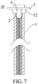
- the connecting pipe 1 includes: a body 11 and a fixing component 12.
- An inner wall of at least one end of the body 11 is provided with a generally annular containing groove, an end surface of one end of the containing groove is flush with an end surface of one end of the body 11, and the nut 2 is arranged in the containing groove.
- the containing groove is a generally annular containing groove, the shape of the cross section of the containing groove is matched with the shape of the cross section of the nut 2, and the end surface of one end of the containing groove is flush with the end surface of one end of the body 11.
- the containing groove can be processed by a milling process, thereby facilitating the processing.
- At least a part of the fixing component 12 is positioned on the end surface of one end of the body 11 so as to limit the nut 2 in the containing groove.
- the fixing component 12 is welded with the body 11 to be connected, so that at least a part of the fixing component 12 is positioned on the end surface of one end of the body 11, and the nut 2 is limited in the containing groove so as to enable the structure to be reliable.
- the fixing component 12 includes a first part and an annular second part, the first part is connected to a peripheral wall of the second part and is generally perpendicular to the second part, and when the second part is disposed on the end surface of one end of the body 11, the first part is disposed on the peripheral wall of one end of the body 11, thereby being favorable for further realizing reliable connection between the fixing component 12 and the body 11.
- the first part is also formed annular, so that when the second part is disposed on the end surface of one end of the body 11, the first part is disposed on the whole circumferential direction of the peripheral wall of one end of the body 11.
- the present invention is not limited thereto.
- the fixing component 12 is integrally disposed on the end surface of one end of the body 11.
- one end, away from the body 11, of the fixing component 12 is provided with an annular groove 121, and when the fastener 4 penetrates through the fixing hole on the connecting plate 3 and is in threaded fit with the nut, at least a part of the connecting plate 3 can be contained in the groove 121 so as to realize reliable connection between the connecting plate 3 and the connecting pipe 1.
- the outer diameter of the second part is equal to the outer diameter of the body 11, thereby being favorable for further optimizing the structure of the fixing component 12, and facilitating reliable cooperation between the fixing component 12 and the body 11.
- the connecting plate 3 is a high-strength steel component or a carbon steel component.
- the seat according to the embodiments of the present invention includes the connecting assembly 100.
- the seat can include a seat basin and the connecting assembly 100.
- One end of the connecting plate 3 is disposed on the seat basin, the fastener 4 can penetrate through the fixing hole on the connecting plate 3 and is in threaded fit with the pre-buried nut 2 in the connecting pipe 1, thereby fixing the connecting pipe 1 on the seat basin to achieve the effect of supporting the seat basin.
- the seat according to the embodiments of the present invention is provided with the connecting assembly 100, thereby realizing connection between the connecting plate 3 of the steel material and the connecting pipe 1 of the light alloy material, solving the problem of connection between the light alloy and the steel component, and being favorable for reducing the mass of the seat.
- the vehicle according to the embodiments of the present invention includes the seat.
- the vehicle according to the embodiments of the present invention is provided with the seat, thereby being favorable for reducing the overall mass of the vehicle, and reducing the energy consumption of the vehicle.
- a manufacturing method of the connecting assembly 100 according to the embodiments of the present invention is described below.
- the manufacturing method of the connecting assembly 100 includes the following steps: firstly, milling one end of the body 11 to process the containing groove, and putting the nut 2 into the containing groove; and secondly, welding the annular fixing component 12 to the end surface of one end of the body 11, then, enabling the fixing hole in the connecting plate 3 to be corresponding to one end, having the annular fixing component 12, of the connecting pipe 1, and enabling the bolt to penetrate through the fixing hole so as to be in threaded fit with the nut 2, thereby realizing processing and manufacturing of the connecting assembly 100.
- the manufacturing method of the connecting assembly 100 solves the problem of connection between the light alloy and the steel component, and realizes connection between the connecting plate 3 of the steel material and the connecting pipe of the light alloy material.
Landscapes
- Engineering & Computer Science (AREA)
- General Engineering & Computer Science (AREA)
- Mechanical Engineering (AREA)
- Aviation & Aerospace Engineering (AREA)
- Transportation (AREA)
- Ocean & Marine Engineering (AREA)
- Connection Of Plates (AREA)
- Standing Axle, Rod, Or Tube Structures Coupled By Welding, Adhesion, Or Deposition (AREA)
Applications Claiming Priority (2)
| Application Number | Priority Date | Filing Date | Title |
|---|---|---|---|
| CN201611076754.0A CN108119447A (zh) | 2016-11-29 | 2016-11-29 | 轻质合金连接组件及其制造方法、座椅和车辆 |
| PCT/CN2017/107686 WO2018099213A1 (zh) | 2016-11-29 | 2017-10-25 | 连接组件及其制造方法、座椅和车辆 |
Publications (2)
| Publication Number | Publication Date |
|---|---|
| EP3550159A1 true EP3550159A1 (de) | 2019-10-09 |
| EP3550159A4 EP3550159A4 (de) | 2019-11-27 |
Family
ID=62226008
Family Applications (1)
| Application Number | Title | Priority Date | Filing Date |
|---|---|---|---|
| EP17875266.3A Withdrawn EP3550159A4 (de) | 2016-11-29 | 2017-10-25 | Verbindungsanordnung und herstellungsverfahren dafür, sitz und fahrzeug |
Country Status (5)
| Country | Link |
|---|---|
| US (1) | US20210364023A1 (de) |
| EP (1) | EP3550159A4 (de) |
| JP (1) | JP2019535982A (de) |
| CN (1) | CN108119447A (de) |
| WO (1) | WO2018099213A1 (de) |
Families Citing this family (2)
| Publication number | Priority date | Publication date | Assignee | Title |
|---|---|---|---|---|
| CN113819122B (zh) * | 2021-09-23 | 2022-11-08 | 扬州三劦紧固件有限公司 | 一种高强度连接紧固件及其制造方法 |
| CN114562499B (zh) * | 2022-03-14 | 2023-05-05 | 东莞职业技术学院 | 增强型铝合金榫卯结构 |
Family Cites Families (12)
| Publication number | Priority date | Publication date | Assignee | Title |
|---|---|---|---|---|
| GB2169678B (en) * | 1985-01-16 | 1988-11-23 | Ward Building Systems Ltd | Method of providing a member with a male or female threaded insert |
| CN2061226U (zh) * | 1990-02-22 | 1990-08-29 | 刘宝良 | 预埋式方便紧固件 |
| DE19826732B4 (de) * | 1998-06-16 | 2007-03-29 | Euromotive Ges.M.B.H. | Rücklehnenkonstruktion |
| CN201125906Y (zh) * | 2007-06-22 | 2008-10-01 | 哈尔滨通达工业环保自动化有限公司 | 尼龙安装座 |
| CN103895536B (zh) * | 2012-12-28 | 2016-04-27 | 比亚迪股份有限公司 | 一种座椅角度调节装置 |
| CN103174824B (zh) * | 2013-03-27 | 2016-06-15 | 宁波高发汽车控制系统股份有限公司 | 一种汽车换挡机构 |
| CN203272376U (zh) * | 2013-04-22 | 2013-11-06 | 宁波江东嘉越国际贸易有限公司 | 一种膨胀螺栓用的套管 |
| DE202014002205U1 (de) * | 2014-03-08 | 2015-06-10 | Robert Bosch Gmbh | Verbinder und Tragvorrichtung mit Verbinder |
| DE102014110830A1 (de) * | 2014-07-30 | 2016-02-04 | Dr. Ing. H.C. F. Porsche Aktiengesellschaft | Einrichtung zum Befestigen einer Abschleppstange oder eines Abschleppseils |
| JP6434059B2 (ja) * | 2015-02-10 | 2018-12-12 | 新日鐵住金ステンレス株式会社 | 面シール性に優れた自動車フランジ用フェライト系ステンレス熱延鋼板および鋼帯ならびにそれらの製造方法 |
| CN104806613B (zh) * | 2015-04-28 | 2017-01-18 | 无锡艾克赛尔栅栏有限公司 | 窗户护栏的墙面固定件 |
| CN105257636B (zh) * | 2015-11-02 | 2017-05-10 | 江苏金陵体育器材股份有限公司 | 篮板连接件与拉杆的连接结构 |
-
2016
- 2016-11-29 CN CN201611076754.0A patent/CN108119447A/zh active Pending
-
2017
- 2017-10-25 EP EP17875266.3A patent/EP3550159A4/de not_active Withdrawn
- 2017-10-25 JP JP2019528490A patent/JP2019535982A/ja not_active Withdrawn
- 2017-10-25 US US16/464,617 patent/US20210364023A1/en not_active Abandoned
- 2017-10-25 WO PCT/CN2017/107686 patent/WO2018099213A1/zh not_active Ceased
Also Published As
| Publication number | Publication date |
|---|---|
| WO2018099213A1 (zh) | 2018-06-07 |
| EP3550159A4 (de) | 2019-11-27 |
| US20210364023A1 (en) | 2021-11-25 |
| JP2019535982A (ja) | 2019-12-12 |
| CN108119447A (zh) | 2018-06-05 |
Similar Documents
| Publication | Publication Date | Title |
|---|---|---|
| CN102126540B (zh) | 系拴组件 | |
| KR20120026495A (ko) | 마그네슘 합금의 선형체, 볼트, 너트 및 와셔 | |
| US9328762B2 (en) | Pierce nut for high-strength steel plate | |
| US20210018032A1 (en) | Self-clinching fastener | |
| US20210364023A1 (en) | Connecting assembly and manufacturing method thereof, seat and vehicle | |
| CN108529417B (zh) | 一种喷管吊具 | |
| EP3168485A1 (de) | Spannungsanzeigescheibe mit versetzten erhebungen und vertiefungen | |
| KR102770089B1 (ko) | 자체 고정 패스너 | |
| CN108127368A (zh) | 一种孔与轴的装配工装及装配方法 | |
| JP5773880B2 (ja) | 薄肉ジョイント部材の製造方法 | |
| US11286972B2 (en) | Fastening member | |
| CN105179688A (zh) | 压力容器卡块连接紧固结构 | |
| EP3856427B1 (de) | Spannband | |
| US10027042B2 (en) | Swage high voltage cable terminal | |
| CN207762098U (zh) | 螺栓 | |
| CN205078775U (zh) | 一种压力容器卡块连接紧固结构 | |
| CN111036741B (zh) | 一种高温扭转制备多层金属复合材料的方法 | |
| CN202073882U (zh) | 用于冲压件的自攻螺钉连接装置 | |
| US20250327476A1 (en) | Banjo bolt | |
| JP7403109B2 (ja) | アルミニウム合金製ボルトおよびその製造方法 | |
| CN212652704U (zh) | 一种环状薄壁类零件装夹装置 | |
| CN113819122B (zh) | 一种高强度连接紧固件及其制造方法 | |
| CN101885370B (zh) | 一种适用于安装在结构中的栓系组件 | |
| CN205786707U (zh) | 电测夹具 | |
| CN220622408U (zh) | 一种连接件结构 |
Legal Events
| Date | Code | Title | Description |
|---|---|---|---|
| STAA | Information on the status of an ep patent application or granted ep patent |
Free format text: STATUS: THE INTERNATIONAL PUBLICATION HAS BEEN MADE |
|
| PUAI | Public reference made under article 153(3) epc to a published international application that has entered the european phase |
Free format text: ORIGINAL CODE: 0009012 |
|
| STAA | Information on the status of an ep patent application or granted ep patent |
Free format text: STATUS: REQUEST FOR EXAMINATION WAS MADE |
|
| 17P | Request for examination filed |
Effective date: 20190628 |
|
| AK | Designated contracting states |
Kind code of ref document: A1 Designated state(s): AL AT BE BG CH CY CZ DE DK EE ES FI FR GB GR HR HU IE IS IT LI LT LU LV MC MK MT NL NO PL PT RO RS SE SI SK SM TR |
|
| AX | Request for extension of the european patent |
Extension state: BA ME |
|
| A4 | Supplementary search report drawn up and despatched |
Effective date: 20191028 |
|
| RIC1 | Information provided on ipc code assigned before grant |
Ipc: B60N 2/68 20060101ALI20191022BHEP Ipc: F16B 5/06 20060101ALI20191022BHEP Ipc: F16B 7/18 20060101AFI20191022BHEP Ipc: F16B 37/04 20060101ALI20191022BHEP |
|
| DAV | Request for validation of the european patent (deleted) | ||
| DAX | Request for extension of the european patent (deleted) | ||
| STAA | Information on the status of an ep patent application or granted ep patent |
Free format text: STATUS: THE APPLICATION HAS BEEN WITHDRAWN |
|
| 18W | Application withdrawn |
Effective date: 20200320 |